1
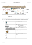
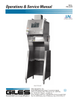
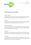
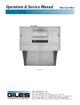
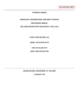
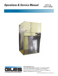
Operations & Service Manual
GBF-35D-VH
GBF-50D-VH
Ventless Operation Supplement GBF-D-VH
Giles Enterprises, Inc.
An ISO9001 Registered Company • Committed to Quality
2750 Gunter Park Drive West • Montgomery, AL 36109 USA
Fax: (334) 239-4117 • www.gfse.com • E-mail: [email protected]
Phone Toll Free: 800.554.4537 (USA & Canada Only)
Form No. 65686-S (Released: 8/11/11; Rev. A)
Installation
1.
Model: GBF-35D-VH, GBF-50D-VH
Installation
This section provides a summary of the procedures necessary for proper installation of your Giles equipment,
Model GBF-50D-VH, GBF-35D-VH. To prevent possible personal injury or damage to equipment, please ensure
the following steps are taken.
1.1
Location
Note:
• Consider that, when operating, the decibel level of the hood unit is approximately 65 dB’s.
1.
Depending on local code, room size and other appliances in use, exhaust ventilation may be
required for the space in which this unit is to be located. This often can be accomplished by
installation of an exhaust fan. To determine the requirement for a specific installation, provide an
HVAC contactor or specialist the following information:
a. The recirculating hood exhausts between 510 to 680 cfm.
b. The average temperature of the air being exhausted from the hood is approximately 90°F (32°C),
after four (4) hours of continuous cooking operations.
2.
This appliance is to be installed, used and maintained in accordance with the Standard for
Ventilation Control, and Fire Protection of Commercial Cooking Operations, NFPA 96-1994.
The above steps will help ensure safe and proper installation. If there are questions concerning these
procedures, contact the nearest Giles Representative or other qualified service agency.
2
Model: GBF-35-VH, GBF-50D-VH
1.2
Installation
Ventless Hood Clearances
The GBF Ventless Hood Fryer series is equipped with a directional exhaust air discharge diverter which
directs air horizontally to the sides and rear. For that reason, zero (0”) clearance is required from the top
of the exhaust diverter to the ceiling.
A clearance of 3” to 6” (76 to 152 cm) is recommended to allow for floor irregularities and to provide
ample head space for moving or repositioning the appliance.
1.3
Ventless Hood Fire Suppression System
The fire suppression system used in the Giles Ventless Hood Fryer is an Ansul R-102 Restaurant Fire
Suppression System (Standard UL 197 Listed). The system consist of piping, discharge nozzles
(appliance & plenum), conduit for fusible link cabling, release mechanism and empty chemical
suppressant tank. Final installation, charging and testing of the system must be performed by an
authorized Ansul distributor in accordance with the system’s listing ... cost of this work is the sole
responsiblity of the purchaser.
The fire suppression system is UL listed to automatically provide fire protection for cooking appliances,
such as fryers, 24 hours per day.
1.4
Fusible Link & Gas Cartridge Locations
Fusible Link, 286°F
Factory Installed
Fusible Link, 165°F
Supplied & Installed by Ansul
Fusible Link 135°F
Supplied & Installed by Ansul
LT-20 R Cartridge
Supplied & Installed by
Ansul
3
Installation
1.5
Model: GBF-35D-VH, GBF35D-VH
Fire Extinguisher Nozzle & Tank Locations
All of the discharge nozzles have been factory installed and aligned in the proper operating position. DO
NOT MOVE OR ADJUST.
Plenum Nozzle
Giles P/N 46426
Plenum Nozzle
Giles P/N 46426
Appliance Nozzles (2)
Giles P/N 46426
Appliance Nozzle
Giles P/N 46426
4
Tank, 1-1/2 Gallon
Giles P/N 40811
Shipped with Unit,
Filled & installed by
Ansul
Model: GBF-35D-VH, GBF-50D-VH
1.6
Installation
Fire Alarm Connection
This connection ties the Fire Suppression System’s release mechanism into a facility fire alarm system,
allowing a signal to be sent to the alarm should the Hood Fire Extinguisher System be activated.
Fire Alarm Connection:
1.
Remove Cover from Fire Alarm Junction Box atop Hood. Route appropriate size conduit and wire
from the Box to the facility’s alarm system control box. Allow enough conduit slack so the Hood can
be accessed for cleaning and servicing.
2.
Make appropriate connections and reinstall junction box cover.
Fire Alarm System
Control Box
Fire Alarm Junction Box
5
Ventless Hood Operation
Model: GBF-35D-VH, GBF-50D-VH
2. Ventless Hood
This section applies to the Ventless Hood (VH) models only. It describes the operation and maintenance of
the Ventless Hood and the Filters contained in the hood.
2.1
Hood Operation
This section describes how to start the Ventless Hood. Make use all the Filters are in place before
operating the unit.
1
3
1
1. Place the Power Switch in the ON
position,
(if ILS, press and hold the Push and Hold to
Start* button for 5 seconds) the Power Light
2 and EAC ON indicator light 3 will come
on.
If equipped with UV option, the Sight Window
4** will illuminate.
This will turn the unit on and the ventless hood
fan will begin running.
2
4**
* Not Shown
** UV Only
2.2
Filters
This section describes each Filter in the Ventless Hood.
2.2.1
Ventless Hood Filter Table
Filter
When to clean or
replace
How to remove
How to clean
How to install
Baffle Filter
Clean Daily
Section7-2.02
Section 7-02.05
Section 7-02.03
EAC Filter
Clean Daily
Section 7-02.06
Section 7-02.09
Section 7-02.07
Section 7-02.10
Never clean, only
replace
Section 7-02.11
Section 7-02.15
Section 7-02.14
Section 7-02.16
Charcoal Filter
Ultra Violet Lamp
6
Replace every 30
days,
P/N 30248
Clean every 30
days
Replace annually
Ventless Hood Operation
Model: GBF-35D-VH, GBF-50D-VH
2.2.2
Baffle Filter Removal
BA
FFL
EF
ILT
ER
BAF
FLE
FIL
TER
1
2
BAF
FLE
FIL
TER
3
TER
LE FIL
BAFF
4
7
Ventless Hood Operation
2.2.3
Model: GBF-35D-VH, GBF-50D-VH
Baffle Filter Installation
2
3
BAF
FLE
FIL
TER
TER
LE FIL
BAFF
1
BAF
FLE
FIL
TER
4
8
BA
FFL
EF
ILT
ER
Switch arm
must be
actuated by
the Baffle
Filter as
shown
Ventless Hood Operation
Model: GBF-35D-VH, GBF-50D-VH
2.2.4
Baffle Filter Missing
If the Baffle Filter is missing or not positioned
correctly the Filter Missing Light 1 will come on.
See Section 2.2.3, Baffle Filter Installation.
1
2.2.5
Baffle Filter Cleaning
The Baffle Filter should be cleaned daily. Place the Baffle Filter in a sink and clean with a mild degreaser.
Dry thoroughly, then reinstall in the unit. Never place wet filter into unit!
2.2.6
EAC Filter Removal
EAC
EAC
9
Ventless Hood Operation
2.2.7
Model: GBF-35D-VH, GBF-50D-VH
EAC Filter Installation
Filter must align
with this pin
EAC
EAC
EAC Air Flow
Arrow must point
upward
2.2.8
EAC Filter Status
The three indicator lights on the Control Panel display the status of the EAC Filter.
1 ON
The EAC Filter is in place, powered
and operating normally.
2 WASH
The EAC Filter has become
excessively dirty and must be
cleaned. If this light is on for more
than 2 minutes, an intermittent alarm
will sound and Fryer heating elements
will be shutdown until the condition is
remedied.
3 CHECK The EAC Filter has stopped operating,
it is either not getting a proper
electrical supply or it has been
damaged. If this light is on for more
than 2 minutes an intermittent alarm
will sound and Fryer heating elements
will be shutdown until the condition is
remedied.
10
1
2
3
Ventless Hood Operation
Model: GBF-35D-VH, GBF-50D-VH
2.2.9
EAC Filter Cleaning
To ensure proper operation, the EAC Filter must be cleaned daily.
Be careful not to bend the collection fins or break the ionizer wires on the EAC cell as this will
prevent the filter from working properly and will cause power to the fryer heating elements to be
shutdown.
1. Add approx. 1/2 gal of a mild degreaser, such as Simple Green or
Clean Magic, to the included Soak Tank 1 . Fill with cold water,
to the full line marked by X’s on inside of tank back, and mix.
2. Holding the contact plate 2 of the EAC
filter into the Soak Tank solution.
3 , slowly lower the
2
3
4
3. After allowing the EAC to soak at least 30 minutes, grasp the
contact plate and jog the cell up and down 4 approximately 1”
to 2” to help remove the grease residue.
4. Slowly remove the EAC from the tank and rinse clean in a sink
using hot water spray.
1
5. Allow the EAC to thoroughly dry.
2.2.10
Charcoal Filter Removal
CH
AR
CO
AL
CH
AR
CO
AL
11
Ventless Hood Operation
2.2.11
Model: GBF-35D-VH, GBF-50D-VH
Charcoal Filter Installation
Switch must be actuated
by the filter
CH
AR
CO
AL
CH
AR
CO
AL
2.-2.12 Charcoal Filter Missing
If the Charcoal Filter is missing or not positioned
correctly and the unit is on, the Filter Missing Light
1 will turn on. See Section 2.2.11, Charcoal
Filter Installation.
1
7.2.13
Charcoal Filter Replacement
Never attempt to clean the Charcoal Filter. Doing so could cause damage to the unit.
Replace the Charcoal Filter every 30 days to maintain proper operation.
Use Replacement Part No. 30248.
12
Ventless Hood Operation
Model: GBF-35D-VH, GBF-50D-VH
2.2.14
Ultra Violet Lamp Cleaning (if equipped)
CAUTION
• DO NOT touch or handle UV Lamp with bare hands.
Doing so will greatly reduce the life of bulb.
Clean UV Lamp at least every 30 days ...
1. Place Fryer power switch in OFF position.
2. Remove Filter Access Cover
3. Remove thumb screws and Lamp Guard. There is no need to remove the lamp.
4. Lightly spray a mild, non-caustic, biodegradable degreaser (such as Simple Green) onto the UV lamp
and use a dry, lint-free cloth to clean bulb. Avoid touching bulb with bare hands.
5. Re-install Lamp Guard and Filter Access Cover.
2.2.15
Ultra Violet Lamp Removal (if equipped)
1. Place Fryer power switch
1
2. Remove Filter Access Cover
in the OFF position.
2 .
2
3
3. Disconnect UV Lamp wiring harness from power
supply wiring harness
3 .
4. Remove thumb screws and UV Lamp Guard
5. Remove Lamp from Holding Brackets
4 .
5 .
4
5
1
13
Ventless Hood Operation
2.2.16
Model: GBF-35D-VH, GBF-50D-VH
Ultra Violet Lamp Installation
1. Install new UV lamp in holding brackets
1 .
2. Install Lamp Guard and tighten thumb
screws 2 .
3
4
3. Connect UV Lamp wiring harness to
power supply wiring harness 3 .
2
1
4. Install all filters and Access Cover
4 .
5. Place Fryer power switch in the ON
position.
2.2.17
Hood Filter Alarm Chart
Alarm Sound
What will happen
Filter
Affected
Continuous tone
Alarm will sound and power
to the Fryer heating
elements will shut off.
Charcoal
(If ILS Model, power to the
Fryer and the Hood section
will shut off)
Continuous tone
Alarm will sound and power
to the Fryer heating
elements will shut off.
(If ILS Model, power to the
Fryer and Hood section will
shut off)
Intermittent tone
Alarm will sound for
two (2) minutes, then
power to the Fryer heating
elements will shut off. (If
ILS Model, power to the
Fryer and Hood section will
shut off)
14
Baffle
E.A.C.
Cause
Solution
Reference
Filter dirty
Replace Filter
Sections
2.2.10 &
2.2.11
Clean Filter
Sections
2.2.2 &
7.2.3
Clean Filter
Sections
2.2.6,
2.2.7,
2.2.8 &
2.2.9
Filter dirty
Filter dirty
Model: GBF-35D-VH, GBF-50D-VH
2.3
Ventless Hood Operation
Maintenance
This Section describes Ventless Hood (VH) System periodic maintenance procedures that will help
maintain its efficiency over time.
A Maintenance and Service Log is provided in this manual, see Table 2.3.6.
2.3.1
Monthly Interlock Check
The Giles Ventless Hood System is equipped with various interlocks that prevent use of the fryer in the
event that conditions for safe and effective operation are not present. Testing of the interlock system
should be conducted MONTHLY to ensure that it remains working properly. Check-off Service Log for
tests performed. If a problem is found call a Giles Service Agent or Technical Support at 800.554.4537.
1.
Baffle Filter Check: Power Switch in the OFF position ... remove the grease baffle filter. Place
Power Switch in the ON position ... place the Selector Switch in the COOK position. The heat light
should not come on. Return power switch and selector switch to OFF and reinstall the grease
baffle filter in the hood.
2.
EAC Filter Check: Remove the EAC cell. Place Power Switch in the ON position ... place the
Selector Switch in the OFF (centered) position. After approx. two (2) minutes and when alarm tone
silences, place Selector Switch to the COOK position. The heat light should not come on. Return
power switch and selector switch to OFF and reinstall the EAC cell.
3.
Charcoal Filter Check: Remove the Charcoal Filter. Place Power Switch in the ON position ...
place the Selector Switch in the COOK position. The heat light should not come on. Return power
switch and selector switch to OFF. Reinstall the charcoal filter.
4.
Filter Clogged Check: Perform this test ONLY when oil is in the fry pot. Place the Power
Switch in the ON position and the Selector Switch in the COOK position. Place a piece of material,
such as cardboard, which is large enough to block the Baffle Filter over it. Within a few seconds an
alarm tone should sound and the heat light will turn off. Return all switches to their OFF positions
and discard the test blockage material.
2.3.2
Quarterly Hood Cleaning
Remove power from the unit at the wall breaker. Remove all Filters from the hood. Used a mild
degreaser to clean the entire hood plenum and blower sections. Be certain to clean the fan blades if
there is evidence of grease build-up. The hood should section should be cleaned at least every 3 months
to help maintain performance, effectiveness and safety..
15
Ventless Hood Operation
2.3.3
Model: GBF-35D-VH, GBF-50D-VH
Semi-Annual Fire Suppression System
Service of the fire suppression system is to be conducted by certified fire protection equipment specialists.
At a minimum, field inspection of the Fire Suppression System must be performed semi-annually by a
qualified fire protection equipment service agent. This semi-annual inspection and service shall consist of the
following.
Place fire extinguishing system locking bar on fire system when servicing hood.
1. Remove charging cartridge, inspect gasket for cuts and elasticity, coat gasket with high-temperature
grease ... reinstall cartridge.
2. Verify suppressant chemical is at proper level in tank ... clean o-ring and coat with high-temperature
grease and reinstall.
3. Check and clean all discharge nozzles of any grease buildup ... verify nozzle protective covers are in
good condition.
4. Test the remote manual pull station for activation and wear.
5. Install test link and conduct simulated automatic actuation test.
6. Clean and inspect fusible links.
7.
Inspect fusible link cabling for wear at pulleys and detectors ... replace if necessary.
8. Record date of inspection and service ... maintain in a permanent file.
2.3.4
Annual Fire Suppression System
This is the same inspection and service as the semi-annual check, except that all fusible links must be
replaced with new links.
2.3.5
12 Year Fire Suppression System
Same as annual service except for the following:
1. Replace R-102 fire suppressant chemical.
2. Hydrostatically test the storage tank and discharge cartridge (replace with new parts that carry current
certifications).
3. Perform flow test on the system regulator.
16
Model: GBF-35D-VH, GBF-50D-VH
Ventless Hood Operation
2.3.6 Maintenance & Service Log
Check
Initial/Date Check
1
2
3
4
ABC 1/2/03
1
2
1
2
3
4
1
2
1
2
3
4
5
1
2
1
2
3
4
1
2
1
2
3
4
1
2
1
2
3
4
5 6*
1
2
1
2
3
4
1
2
1
2
3
4
1
2
1
2
3
4
5
1
2
1
2
3
4
1
2
1
2
3
4
1
2
1
2
3
4
5 6* 7* 8
1
2
1
2
3
4
1
2
1
2
3
4
1
2
1
2
3
4
5
1
2
1
2
3
4
1
2
1
2
3
4
1
2
1
2
3
4
5 6*
1
2
1
2
3
4
1
2
1
2
3
4
1
2
1
2
3
4
5
1
2
1
2
3
4
1
2
1
2
3
4
1
2
1
2
3
4
5 6* 7* 8
1
2
1
2
3
4
1
2
1
2
3
4
1
2
1
2
3
4
5
1
2
1
2
3
4
1
2
1
2
3
4
1
2
1
2
3
4
5 6*
1
2
1
2
3
4
1
2
1
2
3
4
5
1
2
1
2
3
4
5
1
2
1
2
3
4
5
1
2
1
2
3
4
5
1
2
1
2
3
4
5 6* 7* 8
1
2
1 Baffle Filter Check
2 EAC Filter Check
4 Filter Clogged
5 Quarterly Cleaning
7 Fire Suppression System replace Fusible Links
Initial/Date
3
3
3
3
3
3
3
3
3
3
3
3
3
3
3
3
3
3
3
3
3
3
3
3
3
3
3
3
3
3
3
3
3
3
3
3
4
4
4
4
4
4
4
4
4
4
4
4
4
4
4
4
4
4
4
4
4
4
4
4
4
4
4
4
4
4
4
4
4
4
4
4
5
5
6*
5
5
6* 7*
8
5
5
6*
5
5
6* 7*
8
5
5
6*
5
5
6* 7*
8
3 Charcoal Filter Check
6 Fire Suppression System
8 Replace UV Lamp
(UV Option Only)
* Inspection performed by a qualified fire equipment company.
17
Parts List
Model: GBF-35D-VH, GBF-50D-VH
3.1 Front Ventless Hood
**9
2
3
*1
*6
*5
7
8
*4
* Not shown
** UV Only
18
Parts List
3.1
Model: GBF-35D-VH, GBF-50D-VH
Front Ventless Hood
Item
Part Number
Qty.
Description
*1
90254
1
FILTER ACCESS PANEL, ASSY
**1
90262
1
FILTER ACCESS PANEL, ASSY, UV HOOD
2
30248
1
CHARCOAL FILTER ASSY, 20” x 12-3/8” x 2”
3
20520
1
EAC FILTER, 20”
4
42300
1
BAFFLE FILTER, 20” X 20” X 2”
*5
23200
1
SWITCH, SNAP ACTION, ROLLER TYPE
*6
21125
1
EAC CONTACT BOARD
7
30206
1
GREASE DRIP CUP
8
34750
1
DRIP CUP SAFETY PIN
**9
90226
1
UV LAMP ASSY, 16”, REPLACEMENT ONLY
* Not shown
** UV Only
19
Parts List
Model: GBF-35D-VH, GBF-50D-VH
3.2
Rear Ventless Hood
5
***17
4
6
*3 *2 *18
7
1
8
**15 **16
9
10
14
13
* Not shown
** Not shown, ILS only
*** UV Only
20
12
11
Parts List
3.2
Model: GBF-35D-VH, GBF-50D-VH
Rear Ventless Hood
Item
Part Number
Qty.
Description
1
40811
1
S/S ANSUL TANK, 1-1/2 GAL
*2
23778
1
SWITCH, SIDE ROTARY, 240V, 30A, W/O ARM
*3
23779
1
ACTUATOR ARM ADAPTER
4
33589
1
BLOWER ASSEMBLY
5
46125
1
FIRE DAMPER, 10” X 10” (285°F LINK)
6
24237
1
SWITCH, PLUNGER, 250V, 15A
7
20390
1
VACUUM SWTICH, ADJUSTABLE
8
20002
1
SWITCH, SHUTDOWN & ALARM, 15A, 120V, ANSUL
9
40132
1
BRACKET & RELEASE MECHANISM, ANSUL
10
23776
1
ALARM & SHUTDOWN MODULE, AIR FILTER
11
24208
1
EAC POWER SUPPLY, W/DRIVER, 208-240V
12
23751
1
TERMINAL BLOCK
13
23782
1
SONALERT, 250V, CONTINOUS TONE
14
22950
1
SONALERT, 250V, INTERMITTENT TONE
**15
20318
1
RELAY, 240 VAC, 10A
**16
20312
1
BASE, RELAY, PLUG-IN, DIN MOUNT
***17
20373
1
UV-LAMP ASSEMBLY (BALLAST & LAMP)
*18
90054
1
ACTUATOR ARM, BAFFLE SWITCH
* Not shown
** Not shown, ILS only
*** UV Only
21