1
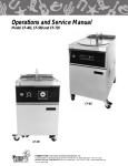
Operations & Service Manual
GEF-400, GEF-560, GEF-720,
GEF-400-VH, GEF-560-VH, &
GEF-720-VH
N7 Computer Controller
Models:
GEF-400
GEF-560
GEF-720
Models:
GEF-400-VH
GEF-560-VH
GEF-720-VH
Giles Enterprises, Inc.
An ISO 9001 Registered Company • Committed to Quality
2750 Gunter Park Drive West • Montgomery, AL 36109 USA
Toll Free: 800.554.4537 (USA & Canada Only) Other: 334.272.1457
Fax: 334.239.4117 • Website: www.gfse.com
Form No. 60831 (Rev. G, 1/2013)
LIMITED WARRANTY
• Subject to the terms and conditions of this Limited Warranty as herein stated, all Giles
Enterprises, Inc., Foodservice Equipment and parts purchased new from an authorized Giles
Enterprises, Inc., representative are warranted as to defects in material or workmanship for a period
of 24 months from the date of installation, provided, however, that with regard to labor costs in
connection with this warranty, see below. All installations must be made by a qualified installing
agency in accordance with all applicable codes and/or regulations in the jurisdiction in which installed.
Limited warranty coverage is extended to the original owner only and is void if the unit is resold.
• During the Limited Warranty period, Giles Enterprises, Inc. will replace or recondition, at its
factory, any part or parts of this unit which Giles Enterprises, Inc. inspectors judge defective, provided
the unit has been subjected to normal usage, properly installed, operated and serviced. This Limited
Warranty does not cover cosmetic damage, and damage due to acts of God, accident, misuse,
alteration, negligence, abuse of the Giles Foodservice Equipment or the use of unorthodox repair
methods. All parts replaced under this Limited Warranty carry only the unexpired term of this Limited
Warranty. Limited Warranty service may be furnished only by an authorized Giles Enterprises, Inc.,
representative.
• If Limited Warranty service is requested, Giles Enterprises, Inc., will send factory-authorized
service representatives to repair, recondition, replace or inspect units of its manufacture with such
labor being rendered without cost to owner for 24 months from the date of installation. Otherwise,
service, including labor and transportation charges or other expenses, in connection with the removal
or installation of any part or parts supplied under this Limited Warranty, are specified on the original
sales contract between the purchaser and the authorized Giles Enterprises, Inc.,
representative.
• Giles Enterprises, Inc. reserves the right to change or improve its equipment and parts in any
way without obligation to alter such equipment or parts previously manufactured.
• Giles Enterprises, Inc. makes no further warranties, express or implied including implied warranties of merchantability or fitness for a particular purpose, and has no other obligation or liability not
specifically stated herein.
• Repair or replacement as provided under this limited warranty is the exclusive remedy. Giles
Enterprises, Inc., shall not be liable for any incidental or consequential damages for breach of any
express or implied warranty on this product, except to the extent prohibited by applicable law. Any
implied warranty of merchantability or fitness for a particular purpose on this product is limited in
duration to the duration of this limited warranty.
• Used Giles Enterprises, Inc., Foodservice Equipment or parts or Giles Enterprises, Inc.,
Foodservice Equipment or parts not purchased from an authorized Giles Enterprises, Inc.,
representative, carry no warranties, express or implied.
Table Of Contents
Safety
Model: GEF-400, GEF-560, GEF-720 &
GEF-400-VH, GEF-560-VH, GEF-720-VH
. . . . . . . . . . . . . . . . . . . . . . . . . . . . . . . . . . . . . . . . . . . . . . . . . . . . . . . vii
Safety Overview . . . . . . . . . . . . . . . . . . . . . . . . . . . . . . . . . . . . . . . . . . . . . . . . . . . . . . . . . . . . . . . . . . . vii
Specific Safety Precautions . . . . . . . . . . . . . . . . . . . . . . . . . . . . . . . . . . . . . . . . . . . . . . . . . . . . . . . . . . viii
1.
Introduction . . . . . . . . . . . . . . . . . . . . . . . . . . . . . . . . . . . . . . . . . . . . . . 1
1.1
1.2
1.3
1.4
1.4.1
1.4.2
1.4.3
1.4.4
1.4.5
Construction . . . . . . . . . . . . . . . . . . . . . . . . . . . . . . . . . . . . . . . . . . . . . . . . . . . . . . . . . . . . . . 1
Standard Features. . . . . . . . . . . . . . . . . . . . . . . . . . . . . . . . . . . . . . . . . . . . . . . . . . . . . . . . . . 1
Optional Features . . . . . . . . . . . . . . . . . . . . . . . . . . . . . . . . . . . . . . . . . . . . . . . . . . . . . . . . . . 1
Specifications . . . . . . . . . . . . . . . . . . . . . . . . . . . . . . . . . . . . . . . . . . . . . . . . . . . . . . . . . . . . . 2
Overall Dimensions for GEF-400, GEF-560, GEF-720 . . . . . . . . . . . . . . . . . . . . . . . . . . . . . . . 2
Overall Dimensions for GEF-400-VH, GEF-560-VH, GEF-720/VH . . . . . . . . . . . . . . . . . . . . . . 3
Regulatory Listings . . . . . . . . . . . . . . . . . . . . . . . . . . . . . . . . . . . . . . . . . . . . . . . . . . . . . . . . . 4
Basket Sizes . . . . . . . . . . . . . . . . . . . . . . . . . . . . . . . . . . . . . . . . . . . . . . . . . . . . . . . . . . . . . . 4
Cooking Capacity . . . . . . . . . . . . . . . . . . . . . . . . . . . . . . . . . . . . . . . . . . . . . . . . . . . . . . . . . . 4
2.
Installation . . . . . . . . . . . . . . . . . . . . . . . . . . . . . . . . . . . . . . . . . . . . . . . 5
2.1
2.2
2.3
2.4
2.4.1
2.4.2
2.5
2.6
2.7
2.8
2.9
2.10
2.11
Location . . . . . . . . . . . . . . . . . . . . . . . . . . . . . . . . . . . . . . . . . . . . . . . . . . . . . . . . . . . . . . . . . 5
Unpacking . . . . . . . . . . . . . . . . . . . . . . . . . . . . . . . . . . . . . . . . . . . . . . . . . . . . . . . . . . . . . . . . 6
Electrical Requirements . . . . . . . . . . . . . . . . . . . . . . . . . . . . . . . . . . . . . . . . . . . . . . . . . . . . . 7
Electrical Connections . . . . . . . . . . . . . . . . . . . . . . . . . . . . . . . . . . . . . . . . . . . . . . . . . . . . . . 9
Routing conduit. . . . . . . . . . . . . . . . . . . . . . . . . . . . . . . . . . . . . . . . . . . . . . . . . . . . . . . . . . . . 9
Service Box Connections . . . . . . . . . . . . . . . . . . . . . . . . . . . . . . . . . . . . . . . . . . . . . . . . . . . 10
Ventilation of Non-Ventless Fryer . . . . . . . . . . . . . . . . . . . . . . . . . . . . . . . . . . . . . . . . . . . . . 10
Ventless Hood Clearances . . . . . . . . . . . . . . . . . . . . . . . . . . . . . . . . . . . . . . . . . . . . . . . . . . 10
Ventless Hood Fire Suppress System. . . . . . . . . . . . . . . . . . . . . . . . . . . . . . . . . . . . . . . . . . 11
Fusible Link and Gas Cartridge Locations . . . . . . . . . . . . . . . . . . . . . . . . . . . . . . . . . . . . . . . 11
Fire Extinguisher Nozzle and Tank Locations . . . . . . . . . . . . . . . . . . . . . . . . . . . . . . . . . . . . 12
Fire Alarm Connection . . . . . . . . . . . . . . . . . . . . . . . . . . . . . . . . . . . . . . . . . . . . . . . . . . . . . 13
Changing the Door Swing. . . . . . . . . . . . . . . . . . . . . . . . . . . . . . . . . . . . . . . . . . . . . . . . . . . 14
3.
Overview . . . . . . . . . . . . . . . . . . . . . . . . . . . . . . . . . . . . . . . . . . . . . . . 15
3.1
3.2
3.3
3.4
3.5
3.6
3.7
Control Panel. . . . . . . . . . . . . . . . . . . . . . . . . . . . . . . . . . . . . . . . . . . . . . . . . . . . . . . . . . . . . 16
Lower Cabinet Area . . . . . . . . . . . . . . . . . . . . . . . . . . . . . . . . . . . . . . . . . . . . . . . . . . . . . . . 18
Filter Pan Assembly . . . . . . . . . . . . . . . . . . . . . . . . . . . . . . . . . . . . . . . . . . . . . . . . . . . . . . . 20
Basket and Elevator Assembly . . . . . . . . . . . . . . . . . . . . . . . . . . . . . . . . . . . . . . . . . . . . . . . 22
Ventless Hood (VH). . . . . . . . . . . . . . . . . . . . . . . . . . . . . . . . . . . . . . . . . . . . . . . . . . . . . . . . 24
Accessories (Included) . . . . . . . . . . . . . . . . . . . . . . . . . . . . . . . . . . . . . . . . . . . . . . . . . . . . . 26
Accessories (Not Included). . . . . . . . . . . . . . . . . . . . . . . . . . . . . . . . . . . . . . . . . . . . . . . . . . 28
4.
Unit Preparation . . . . . . . . . . . . . . . . . . . . . . . . . . . . . . . . . . . . . . . . . 31
4.1
4.2
4.3
4.4
4.5
4.6
Set-up for Initial Testing of Unit . . . . . . . . . . . . . . . . . . . . . . . . . . . . . . . . . . . . . . . . . . . . . . 31
Power Test . . . . . . . . . . . . . . . . . . . . . . . . . . . . . . . . . . . . . . . . . . . . . . . . . . . . . . . . . . . . . . 32
Heating Element Test . . . . . . . . . . . . . . . . . . . . . . . . . . . . . . . . . . . . . . . . . . . . . . . . . . . . . . 32
Filter Pump Test . . . . . . . . . . . . . . . . . . . . . . . . . . . . . . . . . . . . . . . . . . . . . . . . . . . . . . . . . . 33
Perform Boil Out Procedure . . . . . . . . . . . . . . . . . . . . . . . . . . . . . . . . . . . . . . . . . . . . . . . . . 33
Clean Filter Pan. . . . . . . . . . . . . . . . . . . . . . . . . . . . . . . . . . . . . . . . . . . . . . . . . . . . . . . . . . . 33
iii
Model: GEF-400, GEF-560, GEF-720 &
GEF-400-VH, GEF-560-VH, GEF-720-VH
Table Of Contents
5.
Fryer Operation . . . . . . . . . . . . . . . . . . . . . . . . . . . . . . . . . . . . . . . . . . 35
5.1
5.1.1
5.1.2
5.1.3
5.1.4
5.1.5
5.1.6
5.1.7
5.1.8
5.1.9
5.1.10
5.1.10.1
5.1.10.2
5.1.11
5.1.11.1
5.1.11.2
5.2
5.3
5.4
5.5
5.6
Cooking Controller . . . . . . . . . . . . . . . . . . . . . . . . . . . . . . . . . . . . . . . . . . . . . . . . . . . . . . . . 36
Buttons and Functions . . . . . . . . . . . . . . . . . . . . . . . . . . . . . . . . . . . . . . . . . . . . . . . . . . . . . 37
Create or Edit a Menu Program (Temp & Time) . . . . . . . . . . . . . . . . . . . . . . . . . . . . . . . . . . 38
Start a Cooking Cycle . . . . . . . . . . . . . . . . . . . . . . . . . . . . . . . . . . . . . . . . . . . . . . . . . . . . . . 40
Exit or Cancel a Cooking Cycle. . . . . . . . . . . . . . . . . . . . . . . . . . . . . . . . . . . . . . . . . . . . . . . 40
Enter Cool Mode . . . . . . . . . . . . . . . . . . . . . . . . . . . . . . . . . . . . . . . . . . . . . . . . . . . . . . . . . 41
Exit Cool Mode . . . . . . . . . . . . . . . . . . . . . . . . . . . . . . . . . . . . . . . . . . . . . . . . . . . . . . . . . . 41
Lowering and Raising Basket Lift . . . . . . . . . . . . . . . . . . . . . . . . . . . . . . . . . . . . . . . . . . . . . 41
Entering Boil Out Cycle . . . . . . . . . . . . . . . . . . . . . . . . . . . . . . . . . . . . . . . . . . . . . . . . . . . . 42
Exit Boil Out Cycle . . . . . . . . . . . . . . . . . . . . . . . . . . . . . . . . . . . . . . . . . . . . . . . . . . . . . . . . 42
Start-up Procedure . . . . . . . . . . . . . . . . . . . . . . . . . . . . . . . . . . . . . . . . . . . . . . . . . . . . . . . . 43
GEF Model without Ventless Hood . . . . . . . . . . . . . . . . . . . . . . . . . . . . . . . . . . . . . . . . . . . 43
GEF-VH Model with Ventless Hood . . . . . . . . . . . . . . . . . . . . . . . . . . . . . . . . . . . . . . . . . . . 43
Appliance Status Alarms. . . . . . . . . . . . . . . . . . . . . . . . . . . . . . . . . . . . . . . . . . . . . . . . . . . . 44
All Models. . . . . . . . . . . . . . . . . . . . . . . . . . . . . . . . . . . . . . . . . . . . . . . . . . . . . . . . . . . . . . . 44
Ventless Hood Models (VH) . . . . . . . . . . . . . . . . . . . . . . . . . . . . . . . . . . . . . . . . . . . . . . . . . 44
Cooking Procedure . . . . . . . . . . . . . . . . . . . . . . . . . . . . . . . . . . . . . . . . . . . . . . . . . . . . . . . . 45
Filtering Liquid Shortening . . . . . . . . . . . . . . . . . . . . . . . . . . . . . . . . . . . . . . . . . . . . . . . . . . 49
Removal of Liquid Shortening . . . . . . . . . . . . . . . . . . . . . . . . . . . . . . . . . . . . . . . . . . . . . . . 51
Normal Shut-Down . . . . . . . . . . . . . . . . . . . . . . . . . . . . . . . . . . . . . . . . . . . . . . . . . . . . . . . . 54
Emergency Shut-Down. . . . . . . . . . . . . . . . . . . . . . . . . . . . . . . . . . . . . . . . . . . . . . . . . . . . . 54
6.
Cleaning . . . . . . . . . . . . . . . . . . . . . . . . . . . . . . . . . . . . . . . . . . . . . . . . 55
6.1
6.2
6.3
Boil-Out Procedure (Cleaning the Fry Pot) . . . . . . . . . . . . . . . . . . . . . . . . . . . . . . . . . . . . . . 55
Cleaning the Filter Pan & Replacing Filter Media After Boil Out . . . . . . . . . . . . . . . . . . . . . 58
Cleaning the Filter Pan & Replacing the Filter Media Daily . . . . . . . . . . . . . . . . . . . . . . . . . 59
7.
Ventless Hood . . . . . . . . . . . . . . . . . . . . . . . . . . . . . . . . . . . . . . . . . . . 61
7.1
7.1.1
7.1.2
7.1.3
7.1.4
7.1.5
7.1.6
7.1.7
7.1.8
7.1.9
7.1.10
7.1.11
7.1.12
7.1.13
7.1.14
7.1.15
7.1.16
7.2
Filters . . . . . . . . . . . . . . . . . . . . . . . . . . . . . . . . . . . . . . . . . . . . . . . . . . . . . . . . . . . . . . . . . . 61
Ventless Hood Filter Table . . . . . . . . . . . . . . . . . . . . . . . . . . . . . . . . . . . . . . . . . . . . . . . . . . 61
Baffle Filter Removal. . . . . . . . . . . . . . . . . . . . . . . . . . . . . . . . . . . . . . . . . . . . . . . . . . . . . . . 62
Baffle Filter Installation . . . . . . . . . . . . . . . . . . . . . . . . . . . . . . . . . . . . . . . . . . . . . . . . . . . . . 63
Baffle Filter Missing . . . . . . . . . . . . . . . . . . . . . . . . . . . . . . . . . . . . . . . . . . . . . . . . . . . . . . . 64
Baffle Filter Cleaning. . . . . . . . . . . . . . . . . . . . . . . . . . . . . . . . . . . . . . . . . . . . . . . . . . . . . . . 64
EAC Filter Removal . . . . . . . . . . . . . . . . . . . . . . . . . . . . . . . . . . . . . . . . . . . . . . . . . . . . . . . . 64
EAC Filter Installation . . . . . . . . . . . . . . . . . . . . . . . . . . . . . . . . . . . . . . . . . . . . . . . . . . . . . . 65
EAC Filter Operation . . . . . . . . . . . . . . . . . . . . . . . . . . . . . . . . . . . . . . . . . . . . . . . . . . . . . . 65
EAC Filter Cleaning . . . . . . . . . . . . . . . . . . . . . . . . . . . . . . . . . . . . . . . . . . . . . . . . . . . . . . . . 66
Charcoal Filter Removal/Installation . . . . . . . . . . . . . . . . . . . . . . . . . . . . . . . . . . . . . . . . . . . 67
Charcoal Filter Missing . . . . . . . . . . . . . . . . . . . . . . . . . . . . . . . . . . . . . . . . . . . . . . . . . . . . . 67
Charcoal Filter Replacement. . . . . . . . . . . . . . . . . . . . . . . . . . . . . . . . . . . . . . . . . . . . . . . . . 67
Ultra Violet Lamp Cleaning . . . . . . . . . . . . . . . . . . . . . . . . . . . . . . . . . . . . . . . . . . . . . . . . . . 68
Ultra Violet Lamp Removal . . . . . . . . . . . . . . . . . . . . . . . . . . . . . . . . . . . . . . . . . . . . . . . . . . 68
Ultra Violet Lamp Installation . . . . . . . . . . . . . . . . . . . . . . . . . . . . . . . . . . . . . . . . . . . . . . . . 69
Hood Filter Alarm Chart . . . . . . . . . . . . . . . . . . . . . . . . . . . . . . . . . . . . . . . . . . . . . . . . . . . . 69
Maintenance . . . . . . . . . . . . . . . . . . . . . . . . . . . . . . . . . . . . . . . . . . . . . . . . . . . . . . . . . . . . . 70
iv
Table Of Contents
Model: GEF-400, GEF-560, GEF-720 &
GEF-400-VH, GEF-560-VH, GEF-720-VH
7.2.1
7.2.2
7.2.3
7.2.4
Monthly Interlock Check . . . . . . . . . . . . . . . . . . . . . . . . . . . . . . . . . . . . . . . . . . . . . . . . . . . . 70
Quarterly Hood Cleaning . . . . . . . . . . . . . . . . . . . . . . . . . . . . . . . . . . . . . . . . . . . . . . . . . . . 70
Semi-Annual Fire Suppression System . . . . . . . . . . . . . . . . . . . . . . . . . . . . . . . . . . . . . . . . 71
Annual Fire Suppression System . . . . . . . . . . . . . . . . . . . . . . . . . . . . . . . . . . . . . . . . . . . . . 71
7.2.5
7.2.6
12 Year Fire Suppression System . . . . . . . . . . . . . . . . . . . . . . . . . . . . . . . . . . . . . . . . . . . . . 71
Maintenance & Service Log . . . . . . . . . . . . . . . . . . . . . . . . . . . . . . . . . . . . . . . . . . . . . . . . . 72
8.
Troubleshooting . . . . . . . . . . . . . . . . . . . . . . . . . . . . . . . . . . . . . . . . . 73
8.1
Temperature Control System . . . . . . . . . . . . . . . . . . . . . . . . . . . . . . . . . . . . . . . . . . . . . . . . 73
8.2
Oil Filtration System . . . . . . . . . . . . . . . . . . . . . . . . . . . . . . . . . . . . . . . . . . . . . . . . . . . . . . . 76
8.3
8.4
Basket Elevator System . . . . . . . . . . . . . . . . . . . . . . . . . . . . . . . . . . . . . . . . . . . . . . . . . . . . 76
Ultimate Ventless . . . . . . . . . . . . . . . . . . . . . . . . . . . . . . . . . . . . . . . . . . . . . . . . . . . . . . . . . 76
9.
Parts List . . . . . . . . . . . . . . . . . . . . . . . . . . . . . . . . . . . . . . . . . . . . . . . 77
9.1
9.2
9.3
9.4
9.5
9.6
9.7
9.8
Parts Ordering and Service Information . . . . . . . . . . . . . . . . . . . . . . . . . . . . . . . . . . . . . . . . 77
Control Panel & Front Header. . . . . . . . . . . . . . . . . . . . . . . . . . . . . . . . . . . . . . . . . . . . . . . . 78
Front Lower Cabinet . . . . . . . . . . . . . . . . . . . . . . . . . . . . . . . . . . . . . . . . . . . . . . . . . . . . . . . 80
Rear Lower Cabinet . . . . . . . . . . . . . . . . . . . . . . . . . . . . . . . . . . . . . . . . . . . . . . . . . . . . . . . 82
Basket Cover and Basket . . . . . . . . . . . . . . . . . . . . . . . . . . . . . . . . . . . . . . . . . . . . . . . . . . . 84
Filter Pan. . . . . . . . . . . . . . . . . . . . . . . . . . . . . . . . . . . . . . . . . . . . . . . . . . . . . . . . . . . . . . . . 86
Front Ventless Hood . . . . . . . . . . . . . . . . . . . . . . . . . . . . . . . . . . . . . . . . . . . . . . . . . . . . . . . 88
Rear Ventless Hood . . . . . . . . . . . . . . . . . . . . . . . . . . . . . . . . . . . . . . . . . . . . . . . . . . . . . . . 90
v
vi
Model: GEF-400, GEF-560, GEF-720 &
GEF-400-VH, GEF-560-VH, GEF-720-VH
Safety
Safety
Safety Overview
The instructions contained in this manual have been prepared to aid you in learning the proper procedures
for installing and servicing your new Giles Model GEF or GEF-VH Series Fryer.
Throughout this manual, safety precautions are identified through the use of the safety alert symbol and
three signal words: DANGER, WARNING and CAUTION. All safety alert information precedes the
step(s) to which they apply. Suggested, recommended, or other noteworthy information is identified
through the use of NOTES. Additionally, certain words are used to indicate a specific meaning or to add
emphasis.
The following words are used as indicated throughout the manual:
Shall: understood to be mandatory.
Should: understood to be advisory.
May: understood to be permissive.
Will: indicates a future event or condition to occur.
! or !
Used in conjunction with signal words (DANGER, WARNING, or CAUTION) to alert you of potential personal injury hazards, immediately preceding precautionary measures that pertain to subsequent step(s).
Obey all safety messages that follow this symbol to avoid possible injury or death. Failure to adhere to
safety precautions identified by the safety alert symbol may also void the warranty.
!
DANGER
• Indicates an imminently hazardous situation which, if not avoided, will result in death or serious personal
injury.
! WARNING
• Indicates a potentially hazardous situation which, if not avoided, could result in death or serious injury.
! CAUTION
• Indicates a potentially hazardous situation which, if not avoided, may result in minor or moderate injury.
Also used to alert against unsafe practices.
CAUTION
• When used without the safety alert symbol, CAUTION indicates a potentially hazardous situation which,
if not avoided, may result in equipment or property damage, and void the warranty.
NOTE:
• Identifies suggested, recommended, or other noteworthy information.
vii
Model: GEF-400, GEF-560, GEF-720 &
GEF-400-VH, GEF-560-VH, GEF-720-VH
Safety
Specific Safety Precautions
For your safety, please observe the following precautions when operating or servicing your Giles, Model
GEF or GEF-VH Fryer. Read the following important safety information to avoid personal injury and/or
damage to the equipment.
!
DANGER
• Place unit’s power switch in the OFF position and turn off supply power at the facility’s circuit breaker panel
before cleaning or performing maintenance.
• DO NOT hose down the GEF or GEF-VH Fryer’s interior or exterior with water from a spray hose.
• Failure to comply with these DANGER notices will result in death, serious injury or equipment and property damage, and void the warranty.
! WARNING
• Consult a certified electrician to ensure that:
•• all electrical specifications and codes are met.
•• circuit breakers and wiring are of sufficient rating and gauge.
• The GEF Fryer must be properly grounded and all electrical specifications must be met during installation.
• Improper installation, adjustment, alteration, service or maintenance could result in death or serious injury, equipment/property damage, and void the warranty.
• DO NOT use or store gasoline, other flammable liquids or materials that generate flammable vapors in the vicinity of this or any other appliance!
• Failure to comply with WARNING notices could result in death or serious injury, and equipment/property damage
and void the warranty.
! WARNING
GEF-VH MODELS w/ UV LAMP OPTION
•
Internal ultraviolet radiation source present during normal operation. Looking directly into a UV light source
without properly protection will cause serious eye injury!
•
Keep protective tinted sight window in place.
•
Replace all removable panels and covers after servicing.
•
An interlock system is design into the unit to prevent exposure to excessive ultraviolet radiation. DO NOT
attempt to bypass or disable these interlocks.
viii
Safety
Model: GEF-400, GEF-560, GEF-720 &
GEF-400-VH, GEF-560-VH, GEF-720-VH
! CAUTION
• The GEF or GEF-VH Fryer, must remain in an upright (vertical) position.
• Exercise care when removing the unit from from shipping packaging.
• DO NOT operate the Fryer, unless its components and their intended function is fully understood (see Section
3).
• The GEF Fryer, and its parts become very HOT during operation!
Temperatures inside the unit’s cabinet may exceed 150°F (65.5°C).
Exercise caution when operating, loading/unloading food items, cleaning or servicing.
Wearing of thermal oven mitts is recommended.
• Failure to comply with CAUTION notices may result in minor to moderate personal injury, equipment or property
damage, and potentially void the warranty.
! CAUTION
•
Fryers must be adequately and properly grounded. Improper grounding may result in electrical shock.
Always refer to your local electrical code to ensure proper grounding of this or any other electrical equipment. Always consult with an certified electrician or other qualified service person to ensure that electrical
circuits are of sufficient rating for the equipment being operated.
• Giles Electric Fryers are available from the factory wired for various voltage, phase and cycle (Hz). Check the rating
label inside the cabinet or on the rear panel of the unit to determine the correct power supply.
• Before operation, ensure the fry kettle is positioned in a secure, safe location with the casters in the locked position.
• Consult a certified electrician to ensure all electrical specifications have been met and the unit is properly grounded. The wiring diagram provided with the unit should aid an electrician with the installation of the fryer.
• Due to the high temperature of shortening in the fryer during cooking, it is extremely important to exercise caution when operating or working in the vicinity on this equipment to avoid personal injury.
• Before attempting to operate the unit, refer to Section 3 to familiarize yourself with the various control functions.
Once you have read and fully understand Section 3, please follow the steps below precisely in order to prevent
equipment damage or malfunction.
• Take care not to puncture the filter media in the Filter Pan if it becomes necessary to use the Drain Brush to
unclog the drain valve.
• Allow the unit to cool down a minimum of 15 minutes before cleaning or servicing.
• Handle the Electrostatic Air Cleaner (EAC) with care. Do not bend the collection fins and take care not to break
any of the the ionizer wires on the cell. Doing so will prevent the EAC from working properly, potentially causing
the fryer to be disabled.
ix
Model: GEF-400, 560, 720/VH
Safety
CAUTION
• Components exposed on the Control Panel surface are impact-sensitive. Exercise care when working around or
moving carts near the Control Panel to avoid damage and maintain proper operation.
• DO NOT install the unit near combustible walls and materials. Failure to maintain safe distance may result in fire.
• When cleaning the GEF or GEF-VH Series Fryer:
•• DO NOT steam clean.
•• DO NOT use products containing chlorine.
•• DO NOT use abrasive products, steel wool or scouring pads.
•• DO NOT use oven cleaner.
• Failure to comply with these CAUTION notices may result in equipment or property damage, and void the warranty.
• Failure to comply may violate local health codes.
• DO NOT Modify, Alter or Add Attachments to This Equipment!
Note:
• To aid the electrician, an electrical wiring diagram is provided with the unit. Refer to the wiring diagram during
installation or servicing.
• Comply with all appropriate state and/or local heath regulations regarding the cleaning and sanitation of equipment.
• The decibel level of the hood when operating is approximately 65 dB’s.
• Never attempt to clean the Charcoal Filter.
• The appliance and plenum discharge nozzles of the fire suppression system have been factory installed and positioned in the proper alignment. DO NOT MOVE OR ADJUST, except on recommendation of a certified fire
protection specialist.
x
Introduction
1.
Model: GEF-400, GEF-560, GEF-720 &
GEF-400-VH, GEF-560-VH, GEF-720-VH
Introduction
THANK YOU for purchasing a new Giles Model GEF or GEF-VH Series Fryer, manufactured by Giles
Enterprises, Inc., Montgomery, Alabama (USA), hereafter referred to as "Giles". Every unit is thoroughly
inspected and tested prior to shipment, and with proper care and maintenance will provide years of trouble-free service.
To help protect your investment in this state-of-the-art cooking equipment, we recommend that you take a
few moments to familiarize yourself with the installation, operation, cleaning, and maintenance procedures
contained in this manual. Adherence to these recommended procedures will minimize the potential for costly “downtime” and future equipment repairs. Please retain this manual for future reference.
NOTE: Due to continuing improvements and product enhancements, the images shown in this manual might
not exactly depict current models.
1.1
Construction
Model GEF and GEF-VH Fryers are constructed of durable stainless steel.
1.2
Standard Features
Electronic Controller - controls the temperature of the cooking oil and the amount of cooking time. Also
displays alarm conditions and cooking status. 8 programmable menu keys can be preset to different
cooking temperatures and times.
Automatic Basket Lift - automatically lifts cooked product from hot cooking oil at the end of the cooking
cycle.
Oil Filtration System - fully self-contained system, requires only approximately 5 minutes to filter cooking oil and return it the the fry pot.
Ventless Hood Unit Only (GEF-VH):
Ventless Hood - self-contained, type-1, recirculating hood removes grease-laden cooking vapors and
returns clean air into the room, eliminating need for a vent to the outside.
Fire Extinguishing System - self-contained fire extinguishing system protects against an accidental
cooking oil fire.
1.3
Optional Hood Features (GEF-VH)
Ultimate Ventless:
Ultraviolet Lamp works in conjunction with Giles proven air filtration system to sanitize the discharge air
and the hood’s plenum area to assist in reducing or eliminating cooking aromas.
InterLocking Start System (ILS):
When power is interrupted for any reason, this interlock prevents the appliance from restarting without
action by an operator, when power is restored . This ILS interlock is required by some city and/or state
authorities having jurisdiction. Please check with your local code officials to see if this is required for
your area before operating this appliance.
1
Model: GEF-400, GEF-560, GEF-720 &
GEF-400-VH, GEF-560-VH, GEF-720-VH
1.4
Specifications
1.4.1
Overall Dimensions for GEF-400, GEF-560, GEF-720
2
Introduction
Introduction
1.4.2
Model: GEF-400, GEF-560, GEF-720 &
GEF-400-VH, GEF-560-VH, GEF-720-VH
Overall Dimensions for GEF-400-VH, GEF-560-VH, GEF-720-VH
92
[2286.0]
88-3/4
[2254.25]
88-3/4
[2254.25]
Unit is equipped with a 3way exhaust air diverter,
which requires 0” clearance
to ceiling or overhead
obstructions. Recommend
that an allowance of 3” or
more be made to provide
adequate space for movment of the appliance.
3
Model: GEF-400, GEF-560, GEF-720 &
GEF-400-VH, GEF-560-VH, GEF-720-VH
1.4.3
Regulatory Listings
1.4.4
Basket Sizes
Model
Introduction
Basket Size
Diameter
Volume
Height
cubic inch
cubic meter
260.35
1231.83
0.0201
10.25
260.35
1751.45
0.0287
12.75
323.85
2178.63
0.0357
in
mm
in
mm
GEF-400 & GEF-400-VH
12.37
314.19
10.25
GEF-560 & GEF-560-VH
14.75
374.65
GEF-720 & GEF-720-VH
14.75
374.65
1.4.5
Cooking Capacity
Model
Liquid Shortening Capacity
Chicken Capacity
lb
kg
gallon
liter
lb
kg
piece
count
GEF-400 & GEF-400-VH
45
21
5.8
21.9
14
6.3
40*
GEF-560 & GEF-560-VH
60
27
7.8
29.5
19
8.6
56*
GEF-720 & GEF-720-VH
75
37
9.7
36.7
24
10.8
72*
* Approximate based on 2-3/4 lbs per head, bone-in, 8-way cut
4
Installation
2.
Model: GEF-400, GEF-560, GEF-720 &
GEF-400-VH, GEF-560-VH, GEF-720-VH
Installation
This section provides a summary of the procedures necessary for proper installation of your new Giles Model
GEF or GEF-VH Series Fryer. To prevent personal injury or equipment damage, please ensure that the steps
presented in this section are followed.
2.1
Location
Note:
• The decibel level of the hood when operating is approximately 65 dB’s.
CAUTION
• DO NOT MODIFY, ALTER OR ADD ATTACHMENTS TO THIS EQUIPMENT
1.
Keep the appliance and surrounding area free and clear of combustible materials. 3 in. (7.6cm) for
Fryer and 18 in. (46cm) for Ventless Hood.
2.
Please retain this manual for future reference.
3.
A wiring diagram for this appliance has been provided and should be attached inside the cabinet
door. Ensure that it corresponds with this Fryer model, voltage, phase and Hz.
4.
Ensure that this appliance is electrically grounded in accordance with local code, or in the absence
of local code, with the National Electrical Code, ANSI/NFPA NO. 70-1999.
5.
Please provide adequate space for future servicing and proper operation of this appliance. Also,
provide adequate ventilation in the operating area where necessary.
6.
Always consult with a certified electrician or other qualified service technician prior to installation.
7.
Ensure supply voltage and amperage rating of the supply circuit are as specified on the fryer’s rating label.
8.
Make sure this unit is in a secure position and will not unintentionally move. The unit features locking casters ... ensure they are used!
9.
Depending on local code, room size and other appliances in use, exhaust ventilation may be
required. This often can be accomplished by the installation of an exhaust fan in the space in which
the appliance is installed. To determine requirements for your installation, supply the HVAC contractor the following information:
a. The Hood exhausts between 510 to 680 CFM.
b. The average temperature of the air being exhausted from the Hood, after four (4) hours of
continuous frying, is approximately 90°F (32°C).
10.
This appliance is to be installed, used and maintained in accordance with the Standard for
Ventilation Control, and Fire Protection of Commercial Cooking Operations, NFPA 96-1994.
The above steps will help to ensure safe and proper installation of your fryer. If you have any questions concerning these procedures, contact your local Giles distributor or other qualified service person.
5
Model: GEF-400, GEF-560, GEF-720 &
GEF-400-VH, GEF-560-VH, GEF-720-VH
2.2
Installation
Unpacking
The Fryer should arrive enclosed by a wooden crate. It is secured to a wooden skid with high-tensile
strength strapping and wrapped in machine-applied stretch wrap.
! CAUTION
• The appliance must remain in an upright (vertical) position.
• Exercise care when lifting or moving the unit.
• Exercise care when removing the wooden crate from around the unit.
• Failure to comply with these CAUTION notices may result in minor or moderate injury, equipment or
property damage, and void the warranty.
Note:
• If crate exhibited any sign of damage, immediately inspect the unit and notify the carrier of any damages to the unit or included accessory items.
1.
Carefully cut and remove the plastic shipping wrap and strapping. Remove and set aside all auxiliary items packed with the unit.
2.
Use appropriate tools and work practices to remove the wooden crating from around the unit.
3.
Carefully remove the appliance from the shipping skid. The unit is extremely heavy, GEF models
weight 332 lbs (151 kg) and GEF-VH models weight 554 lbs (252 kg). Great care should be taken in
lifting or moving the unit to prevent personal injury or equipment damage. Use appropriate handling equipment or manpower.
6
Model: GEF-400, GEF-560, GEF-720 &
GEF-400-VH, GEF-560-VH, GEF-720-VH
Installation
2.3
Electrical Requirements
! CAUTION
• Fryers must be adequately and properly grounded. Improper grounding may result in electrical
shock. Always refer to local electrical code to ensure proper grounding techniques are used for
this or any other electrical equipment. Always consult with a certified electrician or other qualified
service technician to ensure that the electrical circuit is of sufficient rating for the equipment being
operated.
• These model Fryers are available from the factory wired for the voltages, phases and cycles (Hz) listed
below. Check the serial label found on the rear panel of the fryer or inside the cabinet to determine the
correct power supply.
Table 2.3
Electrical Requirements (Continued on next page)
AMPS
L1
L2
L3
Breaker
Required
10,000
48
48
---
60
3
10,000
29
29
29
40
60
1
10,000
42
42
---
50
240
60
3
10,000
25
25
25
35
GEF-400
380
50
3
9,585
14
14
14
20
GEF-400
415
50
3
10,000
14
14
14
20
GEF-400-VH
208
60
1
10,400
50
50
---
60
GEF-400-VH
208
60
3
10,400
30
30
30
40
GEF-400-VH
240
60
1
10,400
44
44
---
60
GEF-400-VH
240
60
3
10,400
26
26
26
35
GEF-400-VH
380
50
3
9,970
15
15
15
20
GEF-400-VH
415
50
3
10,400
15
15
15
20
Model
Voltage
Hz
Phase
Watts
GEF-400
208
60
1
GEF-400
208
60
GEF-400
240
GEF-400
7
Model: GEF-400, GEF-560, GEF-720 &
GEF-400-VH, GEF-560-VH, GEF-720-VH
2.3
8
Installation
Electrical Requirements (Continued)
AMPS
L1
L2
L3
Breaker
Required
15,000
72
72
---
100
3
15,000
43
43
43
60
60
1
15,000
63
63
---
80
240
60
3
15,000
38
38
38
50
GEF-560
380
50
3
14,375
21
21
21
30
GEF-560
415
50
3
15,000
21
21
21
30
GEF-560-VH
208
60
1
15,400
74
74
---
100
GEF-560-VH
208
60
3
15,400
44
44
44
60
GEF-560-VH
240
60
1
15,400
64
64
---
80
GEF-560-VH
240
60
3
15,400
38
38
38
50
GEF-560-VH
380
50
3
14,770
21
21
21
30
GEF-560-VH
415
50
3
15,400
22
22
22
30
GEF-720
208
60
3
20,000
58
58
58
80
GEF-720
240
60
3
20,000
49
49
49
60
GEF-720
480
60
3
20,000
25
25
25
35
GEF-720
380
50
3
19,166
28
28
28
35
GEF-720
415
50
3
20,000
28
28
28
35
GEF-720-VH
208
60
3
20,400
58
58
58
80
GEF-720-VH
240
60
3
20,400
50
50
50
60
GEF-720-VH
480
60
3
20,400
25
25
25
40
GEF-720-VH
380
50
3
19,600
28
28
28
35
GEF-720-VH
415
50
3
20,400
28
28
28
35
Model
Voltage
Hz
Phase
Watts
GEF-560
208
60
1
GEF-560
208
60
GEF-560
240
GEF-560
Installation
2.4
Model: GEF-400, GEF-560, GEF-720 &
GEF-400-VH, GEF-560-VH, GEF-720-VH
Electrical Connections
1.
Install appropriate sized circuit breaker in main power distribution box. See Table 2.3.
2.
Connect 1-1/4” flexible conduit from main box to Fryer. Allow enough length such that Fryer can be
moved easily for cleaning and servicing. See Figure 2.4.1.
3.
Open Fryer Cabinet Door and remove Service Entrance Box Cover. See Figure 2.4.2.
4.
Route appropriately sized power wires from the circuit breaker in the main box to the Fryer.
5.
Connect power wires to the appropriate Terminal Blocks in the Service Entrance Box. See Figure
2.4.2.
6.
Reinstall Service Entrance Box Cover and close the cabinet door.
2.4.1
Routing conduit
Main Power
Distribution Box
1-1/4” Flexible
Conduit
1-1/4” Straight or 90°
Connector
9
Model: GEF-400, GEF-560, GEF-720 &
GEF-400-VH, GEF-560-VH, GEF-720-VH
2.4.2
Installation
Service Box Connections
Service Entrance Box
Terminal Blocks
Power Wires from Main
Circuit Breaker Box
2.5
Ventilation of Non-Ventless Fryer
Note:
• Guidelines and code for ventilation system requirements may differ from locale to locale. Always consult with the local authorities having jurisdiction to ensure compliance.
Consult a professional, certified ventilation specialist or HVAC company for assistance in specifying the
proper hood and/or ventilation system for this unit.
2.6
Ventless Hood Clearances (VH Model)
GEF Ventless Hood Fryers are equipped with a 3-way exhaust air diverter that directs exhaust air horizontally, to the sides and rear. The minimum clearance from the top of the diverter to the ceiling is 0 inches
(0 mm), however it is recommended to allow 3 to 6 inches (76 - 152 mm) to provide clearance for moving
the unit. The area around the sides and rear of the diverter must be free of obstruction to allow proper air
flow.
10
Installation
2.7
Model: GEF-400, GEF-560, GEF-720 &
GEF-400-VH, GEF-560-VH, GEF-720-VH
Ventless Hood Fire Suppress System
The fire suppression system used in Giles Ventless Hood Fryers is an Ansul R-102 Restaurant Fire
Suppression System (Standard UL197 Listed). Final installation, charging, testing and certification of
the system is to be performed by an authorized ANSUL® distributor in accordance with the system’s listing.
The fire suppression system is designed and UL-listed to provide fire protection for cooking appliances
such as fryers. It automatically protects the appliance 24 hours per day. The self-contained system consist of piping, discharge nozzles (appliance & plenum), fusible link brackets, conduit for fusible link cable,
release mechanism, fire damper, 1.5-gal tank and built-in manual activation station.
2.8
Fusible Link and Gas Cartridge Locations
Fusible Link 286° F
Installed at Factory
Fusible Link 165° F
Supplied & Installed by
ANSUL® agent
Fusible Link 135° F
Supplied & Installed by
ANSUL® agent
Factory -installed Manual
Activation Pull Station
Local authority might
require installation of an
additional remotely
located pull station.
LT-20 R Cartridge
Supplied & Installed by
ANSUL® agent
11
Model: GEF-400, GEF-560, GEF-720 &
GEF-400-VH, GEF-560-VH, GEF-720-VH
2.9
Installation
Fire Extinguisher Nozzle and Tank Locations
All nozzles have been factory installed and aligned in the proper operating position. DO NOT MOVE OR
ADJUST.
Plenum Nozzle
Giles P/N 46426
Plenum Nozzle
Giles P/N 46426
Appliance Nozzle
Giles P/N 46426
Appliance Nozzle
Giles P/N 46426
Tank, 1-1/2 Gallon
Giles P/N 39272
12
Installation
2.10
Model: GEF-400, GEF-560, GEF-720 &
GEF-400-VH, GEF-560-VH, GEF-720-VH
Fire Alarm Connection
This connection sends a signal the facility’s fire alarm system in the event that the appliance fire extinguishing system is activated.
Fire Alarm Connection:
1.
Remove Cover on Fire Alarm Tie-In Box and install appropriately sized conduit and wire to the facility’s fire alarm system. Allow enough length such that the appliance can be moved for access when
cleaning and servicing.
2.
Make appropriate connections.
3.
Reinstall Fire Alarm Tie-In Box Cover.
Facility Fire Alarm
Fire Alarm Tie-in Box
13
Model: GEF-400, GEF-560, GEF-720 &
GEF-400-VH, GEF-560-VH, GEF-720-VH
2.11
Installation
Changing the Door Swing
In some situations the door swing direction may need to be reversed to allow for easier access to the
lower cabinet. The following describes this procedure.
1. Disconnect power.
4
2. Remove (4) screws 1 on the left side of the
lower cabinet.
2
3. Support door; remove (4) 2 screws holding
the top and bottom hinges to the lower cabinet
to remove Cabinet Door.
4. Remove the plastic washer 3 from the bottom hinge and save.
5. Flip the top-right hinge, 4 move it to the bottom left cabinet side and attach; do not tighten.
Place the plastic washer 3 on the hinge pin.
1
5
1
6. Flip the Cabinet Door and hang on the bottomleft hinge pin.
7. Flip the bottom-right hinge, 5 move it the top
left, insert pin into Door and attach hinge to
cabinet side; do not tighten.
8. Check door swing and levelness; adjust as
needed and securely tighten screw.
9. Install (4) screws to right-side of the lower cabinet to fill holes.
5
*6
10.Reconnect power.
11.Order a new Quick Reference Door Label *6
(Part No. 60802) and apply over existing label.
3
* Not shown
14
4
2
3
Overview
Model: GEF-400, GEF-560, GEF-720 &
GEF-400-VH, GEF-560-VH, GEF-720-VH
3. Overview
The following section provides a brief overview of the components, functions, and accessories of the
Giles GEF and GEF-VH Series Electric Fryer. Please review this section carefully before attempting to
operate the appliance.
UV Sight Window
(Optional)
Ventless Hood
Figure 3.5
Basket and Elevator
Assembly
Figure 3.4
Control Panel
Figure 3.1
Lower Cabinet
Area
Figure 3.2
Filter Pan Assembly
Figure 3.3
15
Model: GEF-400, GEF-560, GEF-720 &
GEF-400-VH, GEF-560-VH, GEF-720-VH
3.1
Overview
Control Panel
3
*10
*9
*8
*7
5
4
* Present on Ventless Hood (VH) Models Only
16
6
2
1
Model: GEF-400, GEF-560, GEF-720 &
GEF-400-VH, GEF-560-VH, GEF-720-VH
Overview
3.1
Control Panel
Item
Description
1
Power Switch
Function
The Power Switch is a 2-position Switch. Press top portion to
place in the ON position for operation.
2
Selector Switch
The Selector Switch is a 3-position switch used to select the
mode of operation ... COOK - OFF - FILTER. The fryer‘s heating
elements only operate in the COOK position. The switch is placed
in the FILTER position to start the filter pump for filtering the
shortening.
3
Controller
The Electronic Controller sets and controls cooking oil temperature
and cook times. Displays fryer status and alarm conditions.
High-Limit Indicator
The High-Limit Indicator Light is illuminated when power to the
fryer’s heating elements has been disabled by the solid-state overheat safety control. Should this light come on during operation,
discontinue operation and refer to the Troubleshooting Section
of this manual. NEVER COOK IN A FRYER THAT CONTINUES
TO GIVE A HI-LIMIT ALARM!
4
The Orange Heat Indicator Light is illuminated when the fryer’s
heating elements are energized. When the set-point operating
temperature is reached, the light will turn off. Light will cycle on
and off during normal operation.
The Green Power Light is on whenever the Power Switch is in the
ON position.
The ON Indicator is illuminated when the Electronic Air Cleaner
(EAC) power supply is on. This is the only LED illuminated during
normal operation.
The WASH Indicator is illuminated when the EAC has become
excessively dirty. Do not use this as the signal for routine cleaning; doing so will significantly decrease filter performance and the
life of the charcoal filter. Clean EAC daily for best performance.
5
Heat Indicator Light
6
Power Indicator Light
*7
ON LED Indicator
*8
WASH LED Indicator
*9
CHECK LED Indicator
The CHECK Indicator is illuminated when the EAC becomes shorted and is no longer operating. EAC needs repair or replacement.
*10
Fire Extinguisher
Manual Pull Handle
If fire should occur in the cooking vat, pull this handle to manually
activate the the fire suppression system.
* Present on Ventless Hood (VH) Models Only
17
Model: GEF-400, GEF-560, GEF-720 &
GEF-400-VH, GEF-560-VH, GEF-720-VH
3.2
Overview
Lower Cabinet Area
1
2
5
3
4
6
7
8
Due to continuing improvements and product enhancements, images shown might not exactly depict current models
18
9
Model: GEF-400, GEF-560, GEF-720 &
GEF-400-VH, GEF-560-VH, GEF-720-VH
Overview
3-2. Lower Cabinet Area
Item
Description
Function
1
Diverter Valve Handle
Changes valve setting filter pump output to the cook pot or to the
Oil Discharge Hose.
2
Serial Label
3
Quick Disconnect for
Oil Discharge Hose
Fitting for connecting the Oil Discharge Hose to remove waste oil
from the cook pot.
4
Drain Valve Handle
Operates the cook pot Drain Valve. Always ensure the valve is
closed prior to adding cooking oil or boil out solution. Fryer heating elements are disabled if valve is not completely closed.
5
Quick Disconnect for
Filter Pan Hose
6
Filter Pan Quick
Disconnect Hose
See Section 3.3
7
Filter Pan
See Section 3.3
Show appliance information ... serial number, model, voltage,
phase, cycle (Hz) and watts.
Fitting for connecting the Filter Pan hose to the Oil Filtration
System.
8
Filter Pan Cover
Helps minimize splash when draining hot oil from the cook pot
into the Filter Pan and protects against foreign matter contamination during the filtering process. Fits atop Filter Pan as part of the
assembly, easily removed for cleaning.
9
Cabinet Door
Provides access to lower cabinet functions. Cabinet Door is field
reversible, if needed.
19
Model: GEF-400, GEF-560, GEF-720 &
GEF-400-VH, GEF-560-VH, GEF-720-VH
3.3
Overview
Filter Pan Assembly
2
5
4
6
*7
3
*1
* Not included, Optional Item
20
Model: GEF-400, GEF-560, GEF-720 &
GEF-400-VH, GEF-560-VH, GEF-720-VH
Overview
3.3
Filter Pan Assembly
Item
Description
*1
Crumb Screen
(Optional)
2
Hold Down Frame
3
Filter Paper
4
Hold Down Levers (4)
5
Filter Pan Quick
Disconnect Hose
6
Filter Pan
*7
Stainless Steel Filter
Screen
(Optional)
Function
Captures large crumbs and other cooking residue as the cooking
oil is being drained into Filter Pan for filtering.
Tightly holds and seals filter media in the Filter Pan.
Standard paper filter media, filters finer particles of sediment from
the cooking oil during the a filter cycle. 1 or 2 pieces of paper
media must be used for proper cleaning of cooking oil.
Locks the Hold Down Frame onto the filter media.
Connects Filter Pan to the Oil Filtration System. The hose must
be disconnected for Filter Pan removal.
Contains and filters cooking oil drained from the fry pot. The Filter
Pan is removable for cleaning and renewing of filter media. A perforated screen is permanently attached in the pan bottom to help
prevent debris from entering the filter pump should filter media
become damaged. THIS IS NOT A FILTER ... FILTER MEDIA
MUST ALWAYS BE USED!
Renewable, stainless micro-mesh screen filter media ... replaces
filter paper. Can be removed, cleaned and reused. Features silicone edge gasket for proper seal.
* Not included, Optional Item
21
Model: GEF-400, GEF-560, GEF-720 &
GEF-400-VH, GEF-560-VH, GEF-720-VH
3.4
Overview
Basket and Elevator Assembly
2
1
4
3
Due to continuing improvements and product enhancements, images shown might not exactly depict current models
22
Model: GEF-400, GEF-560, GEF-720 &
GEF-400-VH, GEF-560-VH, GEF-720-VH
Overview
3.4
Basket and Elevator Assembly
Item
Description
Function
1
Basket Cover
Covers the fry pot as product is being cooked. When used as
intended, prevents hot cooking oil from splashing from the fry pot.
2
Basket Carrier
Attaches the Fry Basket to Auto-basket Lift shaft; holds it in the
proper position for lowering, cooking and lifting.
3
Basket
4
Basket Lift
Contains the product during cooking.
Automatically lowers basket into oil for cooking and lifts it from the
fry pot at the end of the cooking cycle.
23
Model: GEF-400, GEF-560, GEF-720 &
GEF-400-VH, GEF-560-VH, GEF-720-VH
3.5
Overview
Ventless Hood (VH)
7
**9
*1
2
3
8
4
* Not Shown
** UV Option Only
24
5
6
Model: GEF-400, GEF-560, GEF-720 &
GEF-400-VH, GEF-560-VH, GEF-720-VH
Overview
3.5
Vestless Hood (VH)
Item
Description
Function
*1
Hood Filter Cover
Provides access the Hood filter chamber and plenum area ... EAC,
Charcoal & UV (if equipped). This cover must be in place and
latched for the unit to operate.
Charcoal Filter
This Filter helps to remove cooking aromas from the exhaust air.
The Filter should be replaced monthly. NEVER attempt to clean
the Charcoal Filter; it is NOT renewable. It is advisable to keep a
spare filter on hand (Gills #30248) for quick exchange when needed!
NOTE: No filter will remove all cooking aromas.
EAC Filter
An Electrostatic Air Cleaner which removes grease vapors and
smoke generated while cooking. The filter is completely renewable
and should be cleaned daily to maintain peak performance.
Appliance power must be turned OFF before removing the EAC
for cleaning.
4
Baffle Filter
The Baffle Filter is the first stage of the grease removal and air cleaning system. It is easily removed for daily cleaning. DO NOT remove
the Baffle Filter while the fryer is operating. Doing so exposes
electrically charged parts and can lead to electric shock.
5
Grease Drip Cup
2
3
Collects grease condensate generated by the Baffle Filter. This
cup should be cleaned daily, or as needed.
6
Grease Drip Cup Safety Secures the Grease Drip Cup, preventing it from unintentionally
Pin
falling from the holding bracket.
7
Located atop the Hood fan discharge outlet. Diverts exhaust air
horizontally to the sides and rear. Allows for 0” clearance require3-Way Diverter Exhaust
ment between the ceiling and top of the diverter. However, it is
Stack
advisable to allow 3” to 6” clearance for ease of moving the appliance when needed.
8
Basket Cover Hanger
**9
Ultraviolet Lamp
(Optional)
Provides a convenient place to hang the Basket Cover when loading, unloading, or stirring product. One is located on either side of
the hood.
Helps to sanitize discharge air and the hood’s plenum area to
improve control of cooking aromas. This lamp should be
cleaned monthly and replaced annually
* Not Shown
** UV Option Only
25
Model: GEF-400, GEF-560, GEF-720 &
GEF-400-VH, GEF-560-VH, GEF-720-VH
3.6
Accessories (Included)
Part
26
Overview
Description/
Part Number
Function
Kettle Drain Brush
P/N 71025
Use for cleaning the Fry Pot and
Pot Drain in the event of clogging.
Stir Paddle
P/N 77775
Use for stirring hot oil and the
product being cooked.
Pot Brush
P/N 71100
Use for cleaning Fry Pot and
Heating Elements.
Crumb Shovel
P/N 30059
Use to remove sediment from the
surface of the filter media in the
Filter Pan after a filtering cycle.
Overview
3.6
Model: GEF-400, GEF-560, GEF-720 &
GEF-400-VH, GEF-560-VH, GEF-720-VH
Accessories (Included)
Part
Description/
Part Number
Function
L-Shaped Brush
P/N 73233
Use for cleaning between
Heating Elements and the space
between the pot wall and the elements.
Discharge Hose
P/N 33667
Soak Tank
P/N 39327
UV Lamp
P/N 90226
Use for removing liquid
shortening from unit.
NOTE: NOT to be used to wash
down fry pot.
Use for daily cleaning EAC filter
Lamp for UV equipped models.
(Optional)
Model: GEF-400, GEF-560, GEF-720 &
GEF-400-VH, GEF-560-VH, GEF-720-VH
3.7
Accessories (Not Included)
Part
Description/
Part Number
Function
Filter Paper
P/N 60810
Paper filter media for the Filter
Pan.
Filter Powder
P/N 72004
Fryer Boil-Out
P/N 72003
28
Overview
Filtering aid to help clean the cooking oil during the filtering cycle.
Add to water when performing
Fryer Boil Out help clean the fry
pot and remove cooking reside.
Overview
3.7
Model: GEF-400, GEF-560, GEF-720 &
GEF-400-VH, GEF-560-VH, GEF-720-VH
Accessories (Not Included)
Part
Description/
Part Number
Function
Filter Pan Crumb Screen
P/N 39246
Catches larger crumbs and pieces
of cooking residue as oil drains into
the Filter Pan for filtering. Helps
reduce potential of clogging the filter system.
Stainless Steel Renewable Filter
Screen
P/N 41014
Renewable replacement for Filter
Paper. Durable stainless steel
media can be cleaned and reused
many times. Provides same filtering performance as paper media.
Giles Oil Caddy
P/N 79187
A portable oil disposal container
with capacity for 80 lbs of liquid
waste shortening.
Note: For use with filtered, warm
oil only. No crumbs or debris.
29
Model: GEF-400, GEF-560, GEF-720 &
GEF-400-VH, GEF-560-VH, GEF-720-VH
Notes:
30
Overview
Unit Preparation
4.
Model: GEF-400, GEF-560, GEF-720 &
GEF-400-VH, GEF-560-VH, GEF-720-VH
Unit Preparation
At Giles Enterprises, Inc. we take pride in the quality of our workmanship. Every effort has been made to
ensure that your unit is in optimum operating condition when received. Each unit must pass rigorous quality
control testing prior to shipment. To further ensure that the unit operates to your expectations, we recommend performing a brief functionality check prior to operating it for the first time.
Before attempting to operate the unit, refer to Section 3 and become familiar with the various controls and their function. Once you have read and fully understand Section 3, precisely follow the
steps below to check the unit’s function. Failure to follow these instructions could lead to equipment
damage or malfunction.
4.1
Set-up for Initial Testing of Unit
Ensure that the unit is set-up as follows before proceeding.
1. Power Switch is in the OFF 1 position.
2. Selector Switch is in the OFF 2 position
4
3
2
1
3. Open the Cabinet Door and remove the
Filter Pan.
4. Ensure the Drain Valve Handle is in the
CLOSED 3 vertical position.
5. Ensure the Oil Diverter Valve is in the
TO FRYER 4 vertical position.
6. Remove Basket Cover, Basket Carrier,
and Basket.
31
Model: GEF-400, GEF-560, GEF-720 &
GEF-400-VH, GEF-560-VH, GEF-720-VH
4.2
Unit Preparation
Power Test
The following test will ensure the unit is properly
receiving power.
2
1. Follow steps shown in Section 4.1.
1
2. Ensure the main circuit breaker powering the
unit is ON.
3. Press the Power Switch to the ON 1 position. The green Power Light 2 will come on.
Please proceed to Section 4.3.
If the Power Light does not illuminate, refer
to the Troubleshooting procedures in Section
8.1.
4.3
Heating Element Test
The following test will confirm that the Heating Elements are being properly energized.
CAUTION!! DO NOT touch the Heating Elements. The elements quickly become very hot and skin
contact may result in a severe burn injury.
1. Follow steps in Section 4.1.
2. Ensure Power Switch is in the OFF position.
3. Wipe the Heating Elements 1 with a liberally
wet sponge, such that moisture remains on the
elements.
1
4. Place the Power Switch in the ON 2 position.
5. Wait until Program Key #1 3 illuminates on the
Controller.
6. Place the Selector Switch in the COOK 4 position. Leave it there NO MORE THAN 10 -15 SECONDS and then return it the OFF position
7.
The moisture on the elements should quickly dry
and heat should be felt rising from the pot..
Proceed to Section 4.4.
If the Heating Elements do not dry within 15 - 30
seconds and/or no heat can be felt, refer to the
Troubleshooting procedure in Section 8.1.
32
3
4
2
Unit Preparation
4.4
Model: GEF-400, GEF-560, GEF-720 &
GEF-400-VH, GEF-560-VH, GEF-720-VH
Filter Pump Test
The following test will confirm that the Filter Pump is operating properly.
1
1. Follow steps shown in Section 4-1.
2. Press the Power Switch to the ON 1
position.
3. Open Cabinet Door.
4. Place the palm of the hand over the Quick
Disconnect 2 for the Filter Pan Hose.
3
5. Briefly place the Selector Switch in the
PUMP 3 position then return it to the OFF
position. If suction is felt on the palm while
the pump is running, it is operating correctly. Proceed to Section 4.5.
If no suction is felt or if air seems to be
blowing out of the fitting, refer to the
Troubleshooting procedure in Section 8.2.
4.5
2
Perform Boil Out Procedure
Perform a Boil Out Procedure to remove manufacturing residue, or dirt and debris that may have accumulated
during shipment. See Section 6.1, Boil Out Procedure. After performing the Boil Out Procedure proceed to
Section 4.6.
4.6
Clean Filter Pan
Thoroughly clean the Filter Pan to remove manufacturing residue, or dirt and debris that may have accumulated during shipment. See Section 6.2, Cleaning the Filter Pan and replacing Filter Paper after Boil Out.
Fryer preparation is now complete. Please proceed to the Operation Section.
33
Model: GEF-400, GEF-560, GEF-720 &
GEF-400-VH, GEF-560-VH, GEF-720-VH
Notes:
34
Unit Preparation
Fryer Operation
Model: GEF-400, GEF-560, GEF-720 &
GEF-400-VH, GEF-560-VH, GEF-720-VH
5. Fryer Operation
This section describes operation of the Giles Electric Fryer, Model Series GEF & GEF-VH.
!
DANGER
• Turn off the unit and the main power supply at the fryer’s circuit breaker box before cleaning or performing maintenance.
• DO NOT wash down the unit’s interior or exterior with water from a spray hose.
• Failure to comply with these DANGER notices will result in death or serious injury, equipment or property damage, and void the warranty.
! CAUTION
• Ensure the appliance is positioned in a secure, safe location, and that the casters in the locked position.
• Consult a certified electrician to ensure all electrical requirements have been met and that the unit is
properly grounded. The wiring diagram provided with this unit should aid the electrician during the
installation of your fryer.
• Due to the high temperature of cooking oil during normal cooking operations, it is extremely important
for the user to exercise caution when operating this equipment to avoid personal injury.
35
Model: GEF-400, GEF-560, GEF-720 &
GEF-400-VH, GEF-560-VH, GEF-720-VH
5.1
Fryer Operation
Cooking Controller
The following section describes the functions, features, programming, and operation procedures of the N7
Cooking Controller.
GEF-VH model Control Panel shown
36
Model: GEF-400, GEF-560, GEF-720 &
GEF-400-VH, GEF-560-VH, GEF-720-VH
Fryer Operation
5.1.1
Buttons and Functions
Temp Key - Press this key to set or edit cooking temperature setpoint. Pressing this key
for 5 seconds will display current actual oil temperature on the main display.
Clock Key - Press this key to set or edit cooking time.
Arrow Keys - Use these keys to a). increase or decrease valves when setting time and temperature, b). manually raise or lower basket lift, and c).
scroll through available settings when programming menu keys.
Menu Keys - Use when programming menus or selecting menus for cooking.
Alarm Reset Key - Silences fryer status alarms. On ILS models, pressing this key starts the
appliance after a power failure or at startup.
Activates “COOL” mode ... press for 5 seconds to activate ... press once to deactivate.
Temperature setpoint changes to preset idle time holding temp of 275°F.
Activates “BOIL OUT” mode ... press for 5 seconds to start. Temperature setpoint
changes to 200°F and 30 minutes is set on the timer.
Basket Key - Activates Arrow Keys to operate the basket lift.
Main Display - Displays time and temperature values, and certain
status readouts.
Scrolling Display - Shows various status, alarm & menu information.
37
Model: GEF-400, GEF-560, GEF-720 &
GEF-400-VH, GEF-560-VH, GEF-720-VH
5.1.2
Fryer Operation
Create or Edit a Menu Program
To Begin ... Press Program Key for approx. 5 seconds
A red LED above the key is illuminated
when programming is active.
Main Display reads
PROG
Scrolling Display reads
Choose Menu
Press the Menu Key you wish to program or edit
Main Display reads
FOOD
Scrolling Display will show a Menu
Label
Use Up & Down Arrow
Keys to cycle through the
available Menu Item
Labels.
Stop when a desired Label appears on the display (available Menu
Item Labels are shown below):
BONE OUT WINGS
SPECIAL 2
FISH
CHEESE STIX
BREASTS/THIGHS
BONE IN WINGS
PICKLES
LIVERS
PIES
LEGS/WINGS
MENU #
CORNDOGS
CHICKEN
TATERS
TENDERS
SPECIAL 1
CATFISH
MUSHROOMS
FILLETS
Press Program Key to
Save selection ... Lower
Display will briefly show
Saved Edit
NOTE: Menu Labels are for user
information and convenience only,
selecting a label does not save a preset cooking program ... continue to
next page.
PROGRAMMING CONTINUED ON NEXT PAGE
38
Fryer Operation
Model: GEF-400, GEF-560, GEF-720 &
GEF-400-VH, GEF-560-VH, GEF-720-VH
CONTINUE PROGRAMMING FROM PREVIOUS PAGE
Main Display will indicate
the Menu # being programmed or edited.
Press Clock Key to set or
change Cook Time
Scrolling Display will
change to read Press Time
or Temp ... LEDs over Clock
& Temp Keys flash.
Press Temp Key to set or
change Cook Temperature
OR
Main Display shows
Time or Temp depending
on Key pressed.
Scrolling Display reads
Press Up Or Down
Use Up & Down Arrow
Keys to change setting to
the desired value for Time
or Temp.
Press Program Key to
Save setting ... Scrolling
Display will briefly show
Saved
Repeat step if setting or
changing both Time &
Temp
Press Program Key to
Save & Exit Programming
OR
?
Press another Menu Key to program or edit settings for another
Menu Selection
39
Model: GEF-400, GEF-560, GEF-720 &
GEF-400-VH, GEF-560-VH, GEF-720-VH
5.1.3
Fryer Operation
Start a Cook Cycle
Press the desired Menu Key (LED over Key will illuminate and oil temperature begins
regulating to the setpoint of that menu). Place product into the Fry Basket.
Press the
Basket Key
Press Down Arrow Key To
Lower Basket
NOTE: Basket Lift will be
locked out as long as the
Controller is in the “PREHEAT” state.
Press button for desired Menu program key again (LED should already be illuminated)
Scrolling Display shows current
selected Menu Label ... pressing
Clock Key will display remaining
cook time)
Main Display shows setpoint
of selected Menu ...holding
Temp Key for 5 secs. will display current actual temperature for 20 secs.)
5.1.4
Exit Cook Cycle
Allow the active Timer to complete programmed cook cycle.
OR
Press Key for Menu you wish to stop (Menu LED should already be illuminated).
Main Display shows setpoint
of selected Menu ...holding
Temp Key for 5 secs. will display current actual temperature for 20 secs.)
Scrolling Display shows current
selected Menu Label ... pressing
Clock Key will display remaining
cook time for cycle)
Up Arrow LED will illuminate,
alarm will sound, and Basket will
rise
If Controller Goes Into Alarm State, Alarm Will sound, Basket Will Rise, and Message Will Display.
40
Model: GEF-400, GEF-560, GEF-720 &
GEF-400-VH, GEF-560-VH, GEF-720-VH
Fryer Operation
5.1.5
Entering Cool Mode
To enter Cool Mode, the Display must show “Ready” ... press Cool Key for 5 secs.
Temperature setpoint changes to 275°F and oil will be regulated to that temperature until Cool Mode is
exited. No Menu programs can be activated while in Cool Mode state.
5.1.6
Exiting Cool Mode
To exit Cool Mode , Press Cool Key
Temperature setpoint changes to that of the currently selected Menu program, Fryer enters Preheat state
and begins heating to the setpoint.
5.1.7
Manually Lowering and Raising the Cooking Basket
OR
Press the
Basket Key
Use Up & Down Arrow
Keys to raise or lower
Basket Lift
If Direction Arrow Has Been Pressed, 20 Seconds Must Elapse Before Direction Can Be Changed.
41
Model: GEF-400, GEF-560, GEF-720 &
GEF-400-VH, GEF-560-VH, GEF-720-VH
5.1.8
Fryer Operation
Entering Boil Out Cycle
To begin a Boil Out Cycle, the Display must show “Ready” ... press Boil Out Key for 5 secs.
Scrolling Display reads “Add Boil Out - Power Off to Quit”
Temperature setpoint changes to 200°F and 30 minute timer starts. Basket will rise. No Menu programs
can be activated while in Boil Out state.
5.1.9
Exit Boil Out Cycle
To exit Boil Out Cycle, allow the 30 min. timer to expire or turn Fryer power off.
Scrolling Display shows “Boil
Complete, Cycle Power”.
Controller will return to start-up state when power is restored.
NOTE: Fryer must be properly drained, rinsed and prepared for cooking after the Boil Out cycle is completed. See Section 6, Cleaning
NOTE: Fryer must be properly drained, rinsed and prepared for cooking after a Boil Out cycle. See
Section 6, Cleaning.
42
Fryer Operation
Model: GEF-400, GEF-560, GEF-720 &
GEF-400-VH, GEF-560-VH, GEF-720-VH
5.1.10
Start Up Procedure
5.1.10.1
GEF Model w/o Integral Ventless Hood
2
1
1. Place the Power Switch in the ON 1 position.
Power Light 2 will illuminate and the Cooking
Controller will power-up.
5.1.10.2
GEF-VH Model w/Integral Ventless Hood
Be certain all hood Filters are in place and properly installed, and that the Filter Access Cover is in place
and securely latched before attempting to operate the appliance.
NOTE: The appliance will NOT power-up if the Filter Access Cover is missing or ajar. The sides of
the Cover must seat flush against the Hood front and the pin on the right-hand edge must engage
the cover interlock switch.
1. Standard Model:
Place the Power Switch in the ON 1 position.
Power Light 2 and EAC ON light 3 will illuminate, the ventless hood fan will start, and
Cooking Controller will power-up. If equipped
with UV Option, the lamp glow should be seen
in the sight window **4 of the Filter Access
Cover.
2. Model with ILS Option:
Place the Power Switch in the ON 1 position.
Power Light 2 will illuminate and a constant
tone alarm will sound. The main display will read
PF; the lower scrolling display will read “Power
Failure - push Alarm Reset to Restart”. Press
Alarm Reset key 5 . The alarm will silence,
EAC ON light 3 will illuminate and the ventless hood fan will start. If equipped with the UV
Option, the lamp glow should be seen in the
sight window **4 of the Filter Access Cover.
2
3
1
5
**4
** UV Model Only
43
Model: GEF-400, GEF-560, GEF-720 &
GEF-400-VH, GEF-560-VH, GEF-720-VH
5.1.11
Fryer Operation
Appliance Status Alarms
Certain conditions that could cause unsafe operation (missing or clogged filters, open valves, low oil
level) will activate an alarm tone; the Heating
Elements will be disabled, and a scrolling message
will appear in the lower display.
5.1.11.1
All Models
1. Low Oil Level: Alarm tone sounds and scrolling display reads “Check Oil Level”. The Heating
Element has reached a factory-set maximum temperature and has been shutdown. This is an indication that the oil level in the cook pot is low and that the Heating Element has become exposed, causing a fire risk. Cease cooking activities, place Selector Switch in OFF position, and press the Alarm
Reset key. Add shortening to the FULL mark and resume activities.
2. Drain Valve Open: If the pot drain valve is open, even slightly, when appliance power is ON the alarm
tone sounds and scrolling display reads “Close Drain Valve - Push Alarm Reset”. If the Basket Lift is
down, it will be raised. Heating Elements are disabled as long as the condition exists. Close valve
and press the Alarm Reset key.
5.1.11.2
Ventless (VH) Models
1. Missing Baffle Filter: Alarm tone sounds and scrolling display reads “Install Baffle Filter - Push
Alarm Reset”. Indicates that the Baffle Filter is missing or improperly installed. Heating Elements
are disabled as long as the conditions exist. Install the Baffle Filter or adjust its position, and verify
that the filter switch has been properly actuated. See Section 7.1.2. & 7.1.3, Baffle Filter Removal &
Installation.
2. Missing Charcoal Filter: Alarm tone sounds and scrolling display reads “Install Charcoal Filter Push Alarm Reset”. Indicates that the Charcoal Filter is missing or improperly installed. Heating
Elements are disabled as long as the conditions exist. Install the Charcoal Filter or adjust its position,
and verify that the filter switch has been properly actuated. See Section 7.1.10, Charcoal Filter
Installation.
3. Clogged Filter: Alarm tone sounds and scrolling display reads “Replace Charcoal Filter - Push
Alarm Reset”. Indicates that the Charcoal Filter is clogged, not allowing sufficient airflow through the
Hood. Other airflow restricting conditions will also cause this alarm to activated. Heating Elements
are disabled as long as the conditions exist. Replace the Charcoal Filter and/or check for any other airflow restrictions. See Section 7.1.10 & 7.1.12, Charcoal Filter Installation & Replacement.
4. EAC Filter: Alarm tone sounds and scrolling display reads “Check EAC Unit”. Indicates that the
Electronic Air Cleaner (EAC) unit is missing, improperly installed, dirty, damaged, or has stopped functioning. Heating Elements are disabled as long as this condition exists. Check the EAC status LED’s
to determine the type of issue present. See Section 7.1.6 through 7.1.9, EAC Filter Operation &
Cleaning.
NOTE: If any of these alarm conditions cannot be resolved, contact a factory-authorized service
agent immediately.
44
Fryer Operation
5.2
Model: GEF-400, GEF-560, GEF-720 &
GEF-400-VH, GEF-560-VH, GEF-720-VH
Cooking Procedures
This section describes cooking procedures for the GEF Series Fryers with computer Cooking Controller.
These procedures apply to both GEF and GEF-VH models.
2
1
1. Raise basket lift and remove the Fry Basket.
See Section 5-01.7.
2. Place the Power Switch in the OFF 1 position.
3. Ensure the Selector Switch is in the OFF 2
position.
4. Ensure the Drain Valve is in the fully CLOSED
3 position (handle vertical).
4
5. Fill the Fry Pot with liquid shortening to the
ADD 4 mark. This will allow for expansion of
the shortening when heated. When at cooking
temperature, shortening level should be near
the FULL mark.
3
6. Place the Power Switch in the ON 5 position.
The Power Light 6 will illuminate.
7. Press the desired Menu Button 7 .
9
6
7
8
5
8. Place the Selector Switch in the COOK 8
position. The Heat Light 9 will illuminate and the heating elements will energize
to begin heating shortening to the menu setpoint temperature.
45
Model: GEF-400, GEF-560, GEF-720 &
GEF-400-VH, GEF-560-VH, GEF-720-VH
5.2
Fryer Operation
Cooking Procedure (Continued)
10
9. Using the provided Stir Paddle, frequently stir
the shortening while preheating. Doing so will
result in more evenly cooked product by preventing cool spots within the shortening.
10. Once shortening has initially preheated to the
setpoint temperature, heating elements will
shutdown and the Heat Light 10 will turn off.
When setpoint is reached an alarm will
sound and “Stir” is displayed on the main
display. Press the Alarm Reset key to
silence the alarm. The setpoint alarm must
be acknowledged before a menu can be
started.
11
11. Check the shortening level. It should now be
at, or near, the FULL 11 Level. Add more
shortening if needed.
12. Using the Stir Paddle, vigorously stir the oil
once again until the Heat Light comes back
on and continue stirring until the light
turns off. The shortening should then be
evenly heated and Fryer is ready for cooking.
13. Place the Cooking Basket 12 onto the Basket
Lift Carrier.
12
46
Fryer Operation
5.2
Model: GEF-400, GEF-560, GEF-720 &
GEF-400-VH, GEF-560-VH, GEF-720-VH
Cooking Procedure (Continued)
14. Press the desired Menu Key 13 ; the
Temperature Setpoint will change to the programmed temperature for that Menu.
If the Menu you wish to cook is already
selected, do not press the key at this time.
Doing so will start the cook cycle timer.
13
Recommended full Fryer load (bone-in, 8-way
cut chicken, 2-3/4 lb. bird):
15
GEF-400: 14 Lbs.
32 - 40 pieces
GEF-560: 19 Lbs.
48 - 56 pieces
GEF-720: 24 Lbs.
64 - 72 pieces
16
14
15. Uncooked product may be placed in the Fry
Basket 14 either before or after it has been
lowered into the shortening.
If Basket is lowered before loading, use
extreme caution when placing product into
the HOT shortening; skin contact or splash
can cause severe burns.
Press “Basket” 15 key and then “Down
Arrow” key to lower basket. Fryer must be in
the Ready state for Basket Lift to operate.
17
Press the desired Menu Key 13 again to start
the cook cycle timer. Fryer must be in a
Ready state before cook cycle will begin.
Place the Basket Cover 16 on top of the Fry
Pot.
16. The displays 17 will show remaining cook
time and the food label for the selected Menu.
47
Model: GEF-400, GEF-560, GEF-720 &
GEF-400-VH, GEF-560-VH, GEF-720-VH
5.2
Fryer Operation
Cooking Procedure (Continued)
18
17. After approx. 60% of the programmed cooking time has
elapsed, an alarm sounds and the “Stir” message will
appear in the Main Display. Press the Alarm Reset key
to silence alarm. Wear oven mitts; remove the Basket
Cover and 18 stir the product with the provided Stir
Paddle 19 to separate pieces which may be stuck
together.
19
18. Replace the Basket Cover 18 on the Fry Pot.
19. At the end of the cook cycle, the Fry Basket 20
with cooked product will automatically be raised
from the hot shortening.
20. Allow product to adequately drain. Wear oven
mitts; remove the Basket Cover and hang it on the
Basket Carrier.
21. Lift the Basket off of the Basket Carrier and dump
cooked product into an appropriate container.
22. Appropriate subsequent actions:
a.) Cook another load - return to Step 6 of this
procedure.
b.) Place Fryer into Cool Mode - see Section 5.1.8,
Cool Mode.
c.) Shutdown Fryer - see Section 5.5, Normal
Shutdown.
NOTE: DO NOT forcefully strike a full basket of
product on the edge of Fry Pot or the Basket Carrier in
an attempt to aid in oil drainage. Damage to the
Basket or the equipment can result.
48
20
Fryer Operation
5.3
Model: GEF-400, GEF-560, GEF-720 &
GEF-400-VH, GEF-560-VH, GEF-720-VH
Filtering Liquid Shortening
This section describes filtering liquid shortening using the on-board filtration system. The system recirculates shortening from the Filter Pan, through Filter Media and back to the Fry Pot. By following this
process, shortening life can be increased by up to 50%. The Cooking Controller is preset to alert operators to filter shortening after every fourth (4th) load cooked.
! WARNING Never attempt to filter cold liquid shortening, this can clog the filter pump and
damage the unit. Shortening must be heated to a min. of 200°F (93°C) before attempting to pump.
1
1. After cooking the fourth load, the Cooking Controller
will display FILTER 1 and sound an alarm to indicate
that the shortening must be filtered.
2. Press the Alarm Reset Key 2 to silence alarm.
3. Place the Selector Switch in the OFF 3 position.
4. Wear oven mitts. Open the Cabinet Door, disconnect
the Filter Pan Quick-Disconnect Hose 4 and remove
the Filter Pan 5 from the unit.
3
2
8
7
4
5. Remove Pan Cover 6 . Ensure that Filter Media is
installed correctly (1 sheet of Filter Paper).
6. Distribute approx. 5 oz. of Filter Powder (1-pack, Giles
#72004) over filter media surface .
7.
Replace Filter Pan Cover 6 and reposition the Filter
Pan under the unit. Reconnect the Filter Pan Quick
Disconnect Hose 4 .
!
This process requires that shorten-
DANGER ing to be drained into the Filter Pan.
Failure to have fryer Selector Switch in the OFF position prior to draining may result in fire as the Heating
Elements become exposed. ALWAYS ENSURE SELECTOR SWITCH IS IN THE OFF POSITION BEFORE
DRAINING SHORTENING FROM POT.
8. Ensure Selector Switch is in the OFF 3 position.
Place the Oil Diverter Valve 7 in the TO FRYPOT,
vertical position. Slowly turn the Drain Valve Handle
counterclockwise to the OPEN 8 horizontal position
to allow liquid shortening to drain into the Filter Pan.
6
5
49
Model: GEF-400, GEF-560, GEF-720 &
GEF-400-VH, GEF-560-VH, GEF-720-VH
5.3
Fryer Operation
Filtering Liquid Shortening (Continued)
NOTE: If the Fry Pot does not readily drain, use the
provided Kettle Drain Brush to break up crumbs or
debris in the Fry Pot Drain. Be careful not to puncture the filter media in the filter pan. Doing so
could cause the filter pump to become clogged
with debris and damage the unit.
9. Once the Fry Pot has completely drained into the
Filter Pan, place the Selector Switch in the FILTER
9 position. Leave Drain Valve open.
10. The shortening will begin circulating 10 from the
Filter Pan, through the filter media and back to the
Fry Pot. To achieve sufficient filtration, leave the
Drain Valve open and allow shortening to continually circulate for a minimum of 5 mins.
During this time, use the provided Pot Brush to
clean elements, pot wall and bottom; allow
residue to be flushed out into the Filter Pan.
11. After approx. 5 mins, turn the Drain Valve Handle
to the CLOSE 11 vertical position and allow the
Fry Pot to refill.
9
10
11
13
12. When oil has been completely pumped back to
the Fry Pot, air bubbles will appear at the oil
return. Place the Selector Switch in the OFF 12 ,
position (centered) to stop pump.
13. Ensure the oil is at the proper level, add shortening if needed.
12
14. Wearing Oven Mitts, disconnect QuickDisconnect 13 , remove the Filter Pan and lift off
Cover.
15. Using the provided Crumb Scoop 14 , remove filter sediment from the surface of the Filter Media
and discard.
16. Replace Cover and reinstall Filter Pan.
17. To continue cooking, See Section 5.2, Cooking
Procedure.
To discontinue cooking, See Section 5.5, Normal
Shutdown.
50
14
Fryer Operation
5.4
Model: GEF-400, GEF-560, GEF-720 &
GEF-400-VH, GEF-560-VH, GEF-720-VH
Removal of Liquid Shortening
This section describes how to remove shortening from the Fryer. This must be done before a Boil Out
Procedure can be performed. In this section a Giles Oil Caddy (not included) is referenced as the disposal
container for waste shortening.
! WARNING Never attempt to remove cold liquid shortening using this procedure, this can
clog the filter pump and damage the unit. Shortening must be heated to a min. of 200°F (93°C)
before performing this procedure.
1
2
1. If shortening is cold, heat to 200°F (93°C).
2. Ensure the Power Switch is in the ON 1 position.
3. Ensure the Selector Switch is in the OFF 2 position.
5
4
4. Ensure the Filter Pan 3 is in place and the quick
disconnect hose 4 is connected the to unit.
5. Slowly turn the Drain Valve Handle 5 to the
OPEN horizontal position and allow the Fry Pot to
completely drain.
3
51
Model: GEF-400, GEF-560, GEF-720 &
GEF-400-VH, GEF-560-VH, GEF-720-VH
5.4
Fryer Operation
Removal of Liquid Shortening (Continued)
7
9
11
10
6
8
6. After the Fry Pot has completely drained, turn the Drain Valve Handle to the CLOSED 6 vertical position.
7.
Connect the Discharge Hose 7 to the Discharge Hose Coupling 8 .
8. Place the discharge end into a Hot Oil Disposal Container 9 (Giles Oil Caddy shown).
9. Turn the Oil Diverter Valve to the TO DISCHARGE HOSE 10 horizontal position.
10. Be sure the wear Oven Mitts if holding the Discharge Hose, it will become very hot. Press the
Selector Switch to the PUMP/FILTER 11 position and allow the shortening to pump into the Disposal
Container.
52
Fryer Operation
5.4
Model: GEF-400, GEF-560, GEF-720 &
GEF-400-VH, GEF-560-VH, GEF-720-VH
Removal of Liquid Shortening (Continued)
11. After shortening is removed from the Filter Pan,
place the Selector Switch in the OFF 12 position.
12. Place the Power Switch in the OFF 13 position.
12
14
13
15
13. Turn the Oil Diverter Valve handle to the TO FRYPOT 14 vertical position.
14. Wearing Oven Mitts, remove the Discharge Hose
from the Discharge Hose Coupling 15 and drain
shortening remaining in the hose into the Oil
Disposal Container.
15. Thoroughly clean the Filter Pan and the Filter Pan
Cover.
16. To perform a Boil Out on the unit, see Section 6.1,
Boil Out Procedure.
To shutdown the Fryer, see Section 5.5, Normal
Shut-Down.
53
Model: GEF-400, GEF-560, GEF-720 &
GEF-400-VH, GEF-560-VH, GEF-720-VH
5.5
Fryer Operation
Normal Shut-Down
This section explains the process of shutting the unit down.
1. Place the Selector Switch in the OFF 1 position.
3
1
2. Place the Power Switch in the OFF 2 position,
the Power Light will 3 turn off.
3. If required, turn off the Fryer’s circuit breaker in
the main electrical breaker panel to remove
power to the unit.
2
5.6
Emergency Shut-Down
In case of emergency, remove power to the unit by turning off the facility main circuit breaker.
54
Cleaning
6.
Model: GEF-400, GEF-560, GEF-720 &
GEF-400-VH, GEF-560-VH, GEF-720-VH
Cleaning
This section describes cleaning procedures for GEF Series Conventional and Ventless model Fryers. In
general, the unit should be cleaned daily.
!
DANGER
• DO NOT hose down the unit’s interior or exterior with water.
• Failure to comply with these DANGER notices will result in death or serious injury, equipment or property damage, and void the warranty.
6.1
Boil-Out Procedure (Cleaning the Fry Pot)
This section describes how to clean the Fry Pot, the process is referred to as Boil-Out. A Boil-Out must
be performed before cooking with new equipment and should be performed each time used shortening is
removed from the fryer, before replenishing with fresh shortening.
For proper fryer performance and operation, the Boil-Out procedure should be performed at least every 7
to 14 days.
Although the Boil-Out does not involve a rolling boil, DO NOT, under any circumstances, leave the
fryer unattended during the procedure. The unit must be carefully monitored for Fry Pot overflow
due to unexpected boiling. Fry Pot overflow may result in serious equipment damage.
1. Remove shortening from the unit, see Section 5.4, Removal of
Liquid Shortening.
2
2. Ensure the Drain Valve is in the CLOSED 1 vertical position and
the Power Switch is in the OFF 7 position.
3. Fill the Fry Pot with fresh clean water to the FULL level 2 .
4. Giles Boil-Out #72003 is recommended. Follow the directions on
the container and add the recommend amount of Boil-Out powder to the water. Stir gently to mix.
1
CAUTION: If using a cleaner other than Giles Boil-Out closely follow the manufacturer’s instructions shown on the container. Many commercially available cleaners are caustic
chemicals which require special precautions. If used improperly, these chemicals may cause damage to the equipment
and potential personal injury to the user.
55
Model: GEF-400, GEF-560, GEF-720 &
GEF-400-VH, GEF-560-VH, GEF-720-VH
6.1
Cleaning
Boil Out Procedure (Continued)
5. Press the Power Switch to the ON 3 position.
4
3
6. Press the Selector Switch to the HEAT 4 position.
7.
Press and hold the Boil button 5 for 5 seconds to
place the unit in the Boil Out mode. The solution will
heat to 200°F (93°C). The internal boil out cycle is
preset for 30 minutes.
8. At the completion of the Boil Out cycle time press
the Selector Switch to the OFF 6 position (cen-
5
tered) and the Power Switch to the OFF 7 position.
9. Disconnect Quick Disconnect Hose, remove the Filter
Pan from the Fryer.
DO NOT drain the Boil-Out solution
into the Filter Pan! Contents are
corrosive and will cause damage to the Filter Pan,
the Hold-Down Frame, and the Filter Pump. Failure
to comply may result in minor or moderate injury,
and equipment or property damage, such damage
not cover by the warranty.
! WARNING
9
10. Position a suitable Heat Resistant Container 8 (not
supplied with the unit) beneath the Fryer Drain.
Container used for this step must
be heat resistant up to 300°F
(148°C). Plastic is generally not safe as it may melt
or break. A leak-proof metal container is preferable.
Failure to comply with this caution may result it serious injury.
! CAUTION
11. Slowly turn the Drain Valve Handle to the OPEN 9 ”horizontal” position, drain boil-out solution into catch container.
12. Rinse and flush the Fry Pot thoroughly with hot tap
water. Empty catch container as often as needed,
taking care not to allow it to overflow.
13. Dry the Fry Pot with a clean dry towel. Ensure surfaces
are thoroughly dry before adding fresh shortening.
56
8
6
7
Cleaning
6.1
Model: GEF-400, GEF-560, GEF-720 &
GEF-400-VH, GEF-560-VH, GEF-720-VH
Boil Out Procedure (Continued)
10
13
14. Slowly turn the Drain Valve Handle to the CLOSE 10
”vertical” position.
15. Clean Filter Pan and replace Filter Media; follow directions in Section 6.2, Cleaning of Filter Pan
Components after the Boil Out procedure.
16. Replace Filter Pan Cover 11 on Pan.
17. Position Filter Pan 12 under unit and connect Filter Pan
Quick Disconnect Hose 13 .
18. To begin cooking on the unit, see Section 5.2.
11
12
57
Model: GEF-400, GEF-560, GEF-720 &
GEF-400-VH, GEF-560-VH, GEF-720-VH
6.2
Cleaning
Cleaning Filter Pan & Replacing Filter Media After Boil Out
This section explains the procedure for cleaning the Filter Pan and replacing the Filter Media. This should
be performed each time Boil Out Procedure (Section 5-5) is done.
Use Thermal Mitts for protection from hot parts.
1. Follow the Normal Shut-Down procedure, see
Section 5.5.
2. Remove the Filter Pan 1 from the Fryer;
remove Cover 2 from the Pan.
2
3. Clean and dry Filter Pan Cover thoroughly.
4. If equipped, remove the Crumb Screen *3 ,
clean and dry it thoroughly.
1
5. Using the metal Crumb Scoop provided with the
unit, remove the accumulated filter residue from
the edge of the Hold Down Frame 4 and surface of the Filter Paper 5 .
6. Turn the four Levers 6 to disengage the HoldDown Frame 4 from the Pan bottom.
7.
Remove the Hold-Down Frame 4 , clean and
dry thoroughly.
8. Grasp one end of the Filter Paper 5 and carefully roll up sheet and discard, taking care not to
allow filter debris to fall through the perforated
screen in the Pan bottom.
9. Thoroughly clean and dry the entire Filter Pan.
Be certain to drain all water from the hoses
10. Reassemble Filter Pan, placing one (1) new
sheet of Filter Paper. Ensure that all levers
engage the Hold-Down Frame securely.
11. Replace Cover onto Filter Pan and restall Filter
Pan Assembly under fryer. Reconnect the hose
at quick-disconnect.
* Accessory Item, not included
58
*3
4
Discard used,
replace with
new.
6
5
Cleaning
6.3
Model: GEF-400, GEF-560, GEF-720 &
GEF-400-VH, GEF-560-VH, GEF-720-VH
Cleaning Filter Pan & Replacing Filter Media Daily
Regardless of whether a Boil-out is performed, the Filter Pan must be cleaned daily as described in
Section 6.2. Doing so will keep the Fryer filtration system operating at peak performance.
59
60
Ventless Hood
7.
Model: GEF-400-VH, GEF-560-VH, GEF-720-VH
Ventless Hood
The following section applies to Ventless Hood (VH) model fryers only. It describes operation and maintenance of the Fryer’s integral Ventless Hood System. Be certain all Filters are in place and properly
installed, and that the Filter Access Cover is in place and securely latched before attempting to operate
the appliance. See Section 5.1.10.2, Start-up GEF-VH Model for start up procedure.
NOTE: The appliance will NOT power-up if the Filter Access Cover is missing or ajar. The sides of
the Cover must seat flush against the Hood front and the pin on the right-hand edge must engage
the cover interlock switch.
7.1
Filters
This section discusses each Filter within the Ventless Hood system and describes removal, installation,
cleaning procedures, and specific fryer alarm conditions that will occur if the filter system is not properly
maintained. Maintainance and cleaning must be performed as prescribed to keep the Ventless Hood
Section operating at optimum performance.
7.1.1 Ventless Hood Filter Table
Filter
When to clean or
replace
How to remove
How to clean
How to install
Baffle Filter
Clean Daily
Section7.1.2
Section 7.1.5
Section 7.1.3
EAC Filter
Clean Daily
Section 7.1.6
Section 7.1.9
Section 7.1.7
Charcoal Filter
Replace every 30
days,
P/N 30248
Section 7.1.10
Cannot be cleaned,
REPLACE ONLY
Section 7.1.11
Ultra Violet Lamp
(Optional)
Clean every 30
days;
Replace annually
Section 7.1.15
Section 7.1.14
Section 7.1.16
61
Ventless Hood
Model: GEF-400-VH, GEF-560-VH, GEF-720-VH
7.1.2
Baffle Filter Removal
1
3
2
4
62
Ventless Hood
7.1.3
Model: GEF-400-VH, GEF-560-VH, GEF-720-VH
Baffle Filter Installation
2
3
1
4
Switch arm
must be
actuated by
the Baffle
Filter when
installed, as
shown
63
Ventless Hood
Model: GEF-400-VH, GEF-560-VH, GEF-720-VH
7.1.4
Baffle Filter Missing
If the Baffle Filter is missing or not properly installed,
a constant tone alarm will sound and a “Baffle Filter
Missing” message 1 will scroll on the lower display. See Section 7.2.3, Baffle Filter Installation.
The fryer will be disabled until the condition is corrected.
1
7.1.5
Baffle Filter Cleaning
The Baffle Filter needs to be cleaned daily. Wash the Filter in sink with a mild degreaser and warm water.
Rinse and dry thoroughly; reinstall in the unit. Never place wet or damp Baffle Filter into the hood!
The Baffle Filter may be washed in a dishwasher, if desired.
7.1.6
EAC Filter Removal
Unlatch Filter Access Cover and lift off. Grasp EAC Filter’s Handle and pull cell straight out on an upward
angle.
64
Ventless Hood
7.1.7
Model: GEF-400-VH, GEF-560-VH, GEF-720-VH
EAC Filter Installation
Pin must align with
hole in rear of Filter
EAC Air Flow Arrow must
point upward.
7.1.8
EAC Filter Operation
Three LED indicator lights on the Control Panel display the operational status of the EAC Filter.
1 ON
The EAC Filter is in place and powered. This is the only LED illuminated
when the EAC is functioning normally.
2 WASH
Indicates that the EAC’s collection fins
have become excessively dirty and
must be cleaned. Two (2) minutes
after this LED turns on, an alarm will
sound, the Heat Light will turn off
and Heating Elements will be disabled. “Check EAC Unit” is displayed on Controller. 4
3 CHECK Indicates that the EAC has stopped
operating. Either the filter is not
receiving proper power or it is damaged. Two (2) minutes after this LED
turns on, an alarm will sound, the
Heat Light will turn off and Heating
Elements will be disabled. “Check
EAC Unit” is displayed on Controller.
4
All (3) LED’s illuminated at power-up, indicates
that the EAC cell is NOT installed, or is misaligned. After (2) minutes an alarm will sound
and the Heating Elements will be disabled.
3
2
1
4
NOTE: DO NOT use the WASH indicator as a
signal to perform routine EAC cleaning. The EAC
Cell must be cleaned daily as described in
Section 7.2.9 to maintain peak hood performance.
If NO LED’s illuminate when the Power Switch is ON, the EAC system has an internal fault; a Service
Agent is required.
65
Model: GEF-400-VH, GEF-560-VH, GEF-720-VH
7.1.9
Ventless Hood
EAC Filter Cleaning
The EAC Filter must be cleaned daily to maintain peak hood performance.
Take care not to bend fins or break ionizer wires when handling. This will pre-
! CAUTION vent the EAC cell from working properly and potentially void the warranty.
Ionizer Wires
(9) required
Fins
1. Add 1/2 gal. (64 ozs.) of a mild degreaser concentrate, such as Simple
Green or Clear Magic, to the Soak Tank 1 ; fill with clean water to
FULL line (marked by X’s on inside back panel) and mix. This solution
should last approx. 7 days.
2. Grasping the EAC cell’s Contact Plate 2 , slowly lower it into the Soak
2
3
Tank solution 3 .
3. Allow the EAC to soak for 20 - 30 minutes, then grasp it by the Contact
Plate 2 , lift slightly and jog it up and down repeatedly in the solution
to help dislodge and remove any grease residue.
1
4. Carefully remove the EAC from the tank and rinse it in the sink using
hot water spray.
5. Stand the Cell on end with the Contact Plate UP, and allow it to air dry
thoroughly (preferably overnight) before re-installing into the hood.
NEVER INSTALL A WET EAC CELL IN HOOD!
CAUTION
• The EAC Filter is NOT considered to be dishwasher safe ... DO NOT wash in the dishwasher!
• DO NOT dry the EAC either by running the hood fan to air dry it or running the appliance to heat
dry. This could potentially damage the EAC causing improper operation and void the warranty.
66
Ventless Hood
7.1.10
Model: GEF-400-VH, GEF-560-VH, GEF-720-VH
Charcoal Filter Removal/Installation
Switch must be actuated by the
filter when installed.
Note airflow arrow on label ...
blue fiber-fill side UP.
Unlatch Filter Access Cover and lift off. Grasp Charcoal Filter and pull it straight out on an upward angle.
Reinstall in similar manner with blue fiber-fill side facing UP.
7.1.11
Charcoal Filter Missing
If the Charcoal Filter is missing or not properly
installed, a constant tone alarm will sound and a
“Charcoal Filter Missing” message 1 will scroll
on the lower display. See Section 7.2.10, Charcoal
Filter Installation.
The fryer will be disabled until the condition is corrected.
1
7.1.12
Charcoal Filter Replacement
The Charcoal Filter is a replaceable filter ONLY; it cannot be cleaned. Never attempt to clean the
Charcoal Filter; damage to the equipment could result.
Replace the Charcoal Filter every 30 days ... replacement Giles Part No. 30248.
67
Ventless Hood
Model: GEF-400-VH, GEF-560-VH, GEF-720-VH
7.1.13
Ultra-Violet Lamp Cleaning
If equipped, the Ultra-violet Lamp must to be cleaned every thirty (30) days for optimum performance.
CAUTION
When performing this activity, DO NOT touch or handle the glass portion of the
UV Lamp with bare hands. Doing so can greatly reduce the service life.
1. Place the unit’s power switch in the OFF position.
2. Remove Filter Access Cover.
3. Remove thumb screws and Lamp Guard from Lamp Mounting Brackets; leave lamp in the Brackets.
4. Lightly spray a mild, non-caustic, biodegradable degreaser, such as Simple Green, onto the UV Lamp
bulb. Allow to soak for a few seconds and then wipe off residue with a dry, lint free cloth.
5. Re-install Lamp Guard; tighten thumb screws securely.
7.1.14
Ultra-Violet Lamp Removal
To maintain peak performance, the UV Lamp
should be replaced annually, regardless if it is
still functional.
2
4
1. Place unit’s power switch 1 in the OFF position.
2. Remove Filter Access Cover 2 .
3. Disconnect UV Lamp lead from power supply lead
4 .
4. Loosen and remove thumb screws and UV Lamp
Guard 3 .
5. Remove Lamp from holding brackets 5 .
1
68
3
5
Ventless Hood
7.1.15
Model: GEF-400-VH, GEF-560-VH, GEF-720-VH
Ultra-Violet Lamp Installation
1. Place new UV Lamp into holding brackets 1 .
3
2. Install Lamp Guard and tighten thumb screws
2 securely.
4
3. Connect UV Lamp lead to power supply lead
coming through wall 3 .
4. Install all filters and Access Cover 4 .
2
5. Place Unit’s power switch in ON position.
1
6. Verify Lamp operation.
DO NOT touch or handle the glass portion of
the UV Lamp with bare hands. Doing so can
greatly reduce the service life.
7.1.16
Filter Alarm Chart
Alarm Message
(Scrolling Display)
What will happen
Filter
Affected
Cause
Solution
See Section
“Replace Charcoal
Filter”
w/
Constant tone alarm
Power to the Fryer Heating
Elements will shutdown.
(If ILS, the power to the Fryer and
Hood with shut off)
Charcoal
Filter excessively
dirty - clogged
Replace Filter
7.2.10
Power to the Fryer Heating
“Install Charcoal Filter”
Elements will shut off.
w/
(If ILS, the power to the Fryer and
Constant tone alarm
Hood with shut off)
Charcoal
Filter missing
Install filter
7.2.10
“Install Baffle Filter”
w/
Constant tone alarm
Power to the Fryer Heating
Elements will shut off.
(If ILS, the power to the Fryer and
Hood with shut off)
Baffle
Filter missing
Install Filter
7.2.2 & 7.2.3
“Check EAC Unit”
w/
Beeping tone alarm
Power to the Fryer Heating
Elements will shut off. (If ILS, the
power to the appliance and hood
with shut off)
E.A.C.
Filter dirty
Clean Filter
7.2.6 thru
7.8.9
69
Model: GEF-400-VH, GEF-560-VH, GEF-720-VH
7.2
Ventless Hood
Maintenance
This Section describes periodic maintenance for the Ventless Hood (VH) System, which is vital to maintaining continuing hood efficiency.
A Maintenance & Service Log is provided in this manual, see Table 7.3.6.
7.2.1
Monthly Interlock Check
The Giles Ventless Hood System design incorporates an Interlock System to ensure that unit operation is safe
and effective. Testing of the Interlock System should be conducted MONTHLY as described below. If the
test was successful, check the appropriate box in the Service Log. If a problem was detected, call for service.
1.
Baffle Filter Check: With the Power Switch in the OFF position remove the Baffle Filter. Replace
Access Cover and turn ON power. Place the Selector Switch in the COOK position. The Heat Light
should not turn ON, a constant tone alarm sounds, and the scrolling display should read “Install
Baffle Filter - Press Alarm Reset”. Return Selector Switch to OFF, turn power OFF, and reinstall
the Baffle Filter.
2.
EAC Filter Check: Remove the EAC cell and replace the Access Cover. Turn ON power and confirm that the Selector Switch is in the OFF position. Wait two (2) minutes and move the Selector
Switch to the COOK position. The Heat Light should not turn ON, a beeping alarm tone sounds,
and the scrolling display should read “Check EAC Unit - Press Alarm Reset”. Return Selector
Switch to OFF, turn power OFF, and reinstall the EAC cell.
3.
Charcoal Filter Check: Remove the Charcoal Filter. Replace the Access Cover and turn ON power.
Place the Selector Switch in the COOK position. The Heat Light should not turn ON, a constant
tone alarm sounds, and the scrolling display should read “Install Charcoal Filter - Press Alarm
Reset”. Return all switches to the OFF position and reinstall the charcoal filter.
4.
Filter Clogged Check: Place the Power Switch in the ON position and the Selector Switch in the
COOK position. Place a piece of filter paper, or other suitable material, sized to cover the Baffle
Filter over it. The Heat Light should turn OFF, a constant tone alarm sounds, and the scrolling display should read “Replace Charcoal Filter - Press Alarm Reset”. Return all switches to the OFF
position and remove the test blockage.
7.2.2
Quarterly Ventless Hood Section Cleaning
Remove power from the unit. Remove the Filter Access Cover and all filters from the hood. Use a mild
degreaser to clean the entire Hood Plenum and Blower Sections. The hood must be cleaned every three
(3) months.
70
Ventless Hood
7.2.3
Model: GEF-400-VH, GEF-560-VH, GEF-720-VH
Semi-Annual Fire Suppression System
Service to the fire suppression system must be conducted by qualified fire equipment personnel. As a minimum, field inspection of the Fire Suppression System is to be accomplished semi-annually by a certified fire
equipment company. Such inspection shall consist of the following.
Place Locking Bar on the extinguisher system when servicing hood.
1. Remove charging cartridge, inspect gasket for cuts and elasticity, coat gasket with extreme temperature grease and reinstall. See Section 2-08. Fusible Link and Gas Cartridge Locations
2. Remove tank, verify suppressant chemical is at proper level, clean and coat O-ring with extreme temperature grease and reinstall. See Section 2-09. Fire Extinguisher Nozzle and Tank Locations
3. Check discharge nozzles for signs grease buildup; clean as needed.
4. Inspect remote manual activation station for function and wear.
5. Install test link and simulate automatic actuation.
6. Clean and inspect fusible links. See Section 2-08. Fusible Link and Gas Cartridge Locations
7.
Inspect wire rope for wear at pulleys and detectors; replace as needed.
8. Record maintenance date and maintain in a permanent file.
7.2.4
Annual Fire Suppression System
Same as Semi-Annual, except must include replacement of all fusible links. See Section 2-08. Fusible
Link and Gas Cartridge Locations
7.2.5
12-Year Fire Suppression System
Same as Annual except must include the following:
1. Replace the R-102 fire suppression chemical.
2. Hydrostatically test the tank and cartridge.
3. Flow test the regulator.
71
Ventless Hood
Model: GEF-400-VH, GEF-560-VH, GEF-720-VH
7.2.6
Maintenance & Service Log
Check
1
1
1
1
1
1
1
1
1
1
1
1
1
1
1
1
1
1
1
1
1
1
1
1
1
1
1
1
1
1
1
1
1
1
1
1
2
2
2
2
2
2
2
2
2
2
2
2
2
2
2
2
2
2
2
2
2
2
2
2
2
2
2
2
2
2
2
2
2
2
2
2
3
3
3
3
3
3
3
3
3
3
3
3
3
3
3
3
3
3
3
3
3
3
3
3
3
3
3
3
3
3
3
3
3
3
3
3
4
4
4
4
4
4
4
4
4
4
4
4
4
4
4
4
4
4
4
4
4
4
4
4
4
4
4
4
4
4
4
4
4
4
4
4
5
5
5
5 6* 7* 8
5
5
5
5 6* 7* 8
5
5
5
5 6* 7* 8
Initial/Date
RGS 1/15/10
Check
1
1
1
1
1
1
1
1
1
1
1
1
1
1
1
1
1
1
1
1
1
1
1
1
1
1
1
1
1
1
1
1
1
1
1
1
2
2
2
2
2
2
2
2
2
2
2
2
2
2
2
2
2
2
2
2
2
2
2
2
2
2
2
2
2
2
2
2
2
2
2
2
1 Baffle Filter Check
2 EAC Filter Check
4 Filter Clogged
5 Quarterly Cleaning
7 Fire Suppression System replace Fusible Links
* Inspection performed by certified fire equipment company.
72
3
3
3
3
3
3
3
3
3
3
3
3
3
3
3
3
3
3
3
3
3
3
3
3
3
3
3
3
3
3
3
3
3
3
3
3
4
4
4
4
4
4
4
4
4
4
4
4
4
4
4
4
4
4
4
4
4
4
4
4
4
4
4
4
4
4
4
4
4
4
4
4
Initial/Date
5
5
5
5 6* 7* 8
5
5
5
5 6* 7* 8
5
5
5
5 6* 7* 8
3 Charcoal Filter Check
6 Fire Suppression System
8 Replace UV Lamp
(UV Option Only)
Model: GEF-400, GEF-560, GEF-720 &
GEF-400-VH, GEF-560-VH, GEF-720-VH
Troubleshooting
8.
Troubleshooting
This section describes troubleshooting procedures for Giles Models GEF-400, GEF-560, GEF-720, GEF-400VH, GEF-560-VH and GEF-720-VH Electric Fryers.
8.1
Temperature Control System
Problem
FRYER WILL NOT TURN ON:
No power light
Probable Cause
Repair Procedure
A. Not connected to power
source.
A. Connect to power source.
B. Fuse blown/tripped breaker.
B. Check fuse or breaker.
C. Fuse holder cracked.
C. Replace fuse holder.
D. Power Switch faulty.
D. Replace Power Switch.
E. Improper supply voltage.
E. Connect to proper voltage
source.
F.
F.
Hood Filter Cover not closed.
Close Cover securely.
G. Fire Suppression not armed.
G. Call local Ansul Dealer.
*H.Hold down “Push and Hold to
Start” button for 5 seconds.
* ILS model only
*H.“Push to Start” button not
held down for a full 5 seconds.
FRYER WILL NOT HEAT:
Power light on. Heat light not on.
A. Cook/Filter Switch not in COOK A. Place Cook/Filter Switch in
position.
COOK position.
FRYER WILL NOT HEAT:
Power light on.
Cook/Filter Switch in cook position.
Heat light not on.
A. Selected menu key proA. Set temperature controller to
grammed below current actual
desired temperature.
oil temperature.
B. Drain Valve open message.
B. Close Drain Valve. Reset alarm
C. Cooking computer faulty.
C. Replace Cooking Computer.
D. ERR01 Message / Variable
probe shorted or open.
D. Check wiring/Replace Probe.
E. Filter Missing Message.
E. Install indicated filter
F.
F. Replace faulty contactor.
Contactor failure.
G. Element bad.
G. Replace element.
H. Selector Switch bad.
H. Replace Selector Switch.
I.
I. Reset Breaker
Breaker tripped (single phase)
73
Model: GEF-400, GEF-560, GEF-720 &
GEF-400-VH, GEF-560-VH, GEF-720-VH
8.1
Troubleshooting
Temperature Control System (Continued)
Problem
FRYER WILL NOT HEAT:
Power light on. Selector
Switch in cook position. Filter
missing message on. (VH Model
Only)
Probable Cause
A. Baffle Filter missing.
A. Install Baffle Filter.
B. Baffle Filter not installed
properly.
B. Reinstall Baffle Filter.
C. Charcoal Filter missing.
C. Install Charcoal Filter.
FRYER WILL NOT HEAT:
A. EAC shorted or bent fins.
Power light on. Selector Switch in
B. EAC dirty.
cook position. Heat light not on.
Alarm emitting a BEEPING Tone. C. EAC Power Supply faulty.
(VH Model only)
FRYER WILL NOT HEAT:
Power light on. Selector Switch
in cook position. High Limit light
On.
Repair Procedure
A. Repair EAC.
B. Clean EAC.
C. Replace high voltage Power
Supply
D. EAC wires shorted.
D. Remove shorted condition.
E. Bad Contact Plate.
E. Replace Contact Plate.
F. EAC Module faulty.
F. Replace EAC Module.
A. Power surge.
A. Turn Power Switch off for 5
seconds, restart fryer
B. Plug not completely in.
B. Reconnect to power source.
C. Oil level too low.
C. Fill kettle to FULL mark.
D. Sticking Contactor.
D. Replace Contactor.
E. Bad High Limit Board.
E. Replace High Limit Board.
F. High Limit Probe short or open. F. Replace High Limit Probe.
G. Line spikes or noise.
FRYER WILL NOT HEAT:
A. Charcoal Filter clogged.
Power light on. Selector Switch in
B. Clogged Filter Switch bad.
cook position. Heat light not on.
Alarm emitting a constant tone.
C. Kinked Vacuum Line.
(VH Model only)
D. Fan running slow.
E. Fan running slow.
74
G. Filter Line or remove noise
source.
A. Replace Charcoal Filter.
B. Replace Clogged Filter Switch.
C. Remove Vacuum Line kinks.
D. Check Voltage.
E. Clean fan blades.
Model: GEF-400, GEF-560, GEF-720 &
GEF-400-VH, GEF-560-VH, GEF-720-VH
Troubleshooting
8.1
Temperature Control System (Continued)
Problem
Probable Cause
FRYER HEATS SLOWLY: (slow
A. Incorrect Cooking procedures.
recovery) Heat light constantly on.
FRYER HEATS SLOWLY: (short
cycling) Heat light turning off and
on CONTINUOUSLY.
OIL TEMPERATURE ERRATIC:
OIL SMOKING:
Repair Procedure
A. Consult Operations Manual for
proper Cooking procedure.
B. Element failing.
B. Replace bad Element.
C. Contactor failing.
C. Replace Contactor.
D. Loose Wire.
D. Repair Loose Wire.
E. Low Supply Voltage.
E. Supply proper Voltage.
A. Low supply Voltage.
A. Supply proper Voltage.
B. Variable probe touching element.
B. Reposition variable probe.
C. Cooking Controller faulty.
C. Replace Cooking Controller.
A. Probe bad.
A. Replace Probe.
B. Contactor failing.
B. Replace Contactor.
C. Cooking Controller faulty.
C. Replace Cooking Controller.
D. Loose Wire.
D. Repair loose Wire.
A. Old Oil.
A. Change Oil.
B. Over Temperature.
B. Check temperature setting.
C. Dirty Element.
C. Clean Elements.
D. Element failure.
D. Replace Element.
E. Improper element voltage.
E. Supply proper Voltage.
F. Low Oil level.
F. Keep Oil at FULL Level.
75
Model: GEF-400, GEF-560, GEF-720 &
GEF-400-VH, GEF-560-VH, GEF-720-VH
8.2
Oil Filtration System
Problem
OIL NOT RETURNING TO FRY
POT:
OIL PUMP STICKING
8.3
Repair Procedure
A. Cook/Filter Switch not in
“Filter” position.
A. Place Selector Switch in
“Filter” position.
B. Air Leak (hoses, fittings, filter
paper).
B. Repair Air Leak.
C. Pump Motor Bad.
C. Replace Pump Motor.
D. Oil Pump Sticking.
D. Free Stuck Pump.
A. Boil Out was run through
Pump.
A. Disassemble and Re-Oil Pump.
B. Old Oil allowed to sit in Pump.
B. Run Clean Oil through Pump.
A. Power not on.
A. Press Power Switch to ON
position.
B. Cooking Controller faulty.
B. Replace Cooking Controller.
C. Cooking cycles running.
C. Cancel cooking cycle.
D. Elevator microswitch out of
adjustment.
D. Adjust Elevator microswitch.
E. Elevator microswitch bad.
E. Replace Elevator microswitch.
UV Equipped Hood
UV LAMP NOT ILLUMINATED
76
Probable Cause
Basket Lift System
BASKET WILL NOT GO UP OR
DOWN:
8.4
Troubleshooting
A. Bad connection
A. Reconnect
B. Lamp blown
B. Replace Lamp
C. Filters not installed correctly
C. Install Filters
D. Filter Access Cover not
installed correctly
D. Install Filter Access Cover
E. Bad Ballast
E. Replace Ballast
F. Ballast fuse blown
F. Replace fuse
G. Switch on Ballast has been
turned OFF
G. Turn switch ON.
Parts List
Model: GEF-400, GEF-560, GEF-720 &
GEF-400-VH, GEF-560-VH, GEF-720-VH
9. Parts List
This section lists various parts that are field replacable on the GEF-400, GEF-560, GEF-720, GEF-400-VH,
GEF-560-VH and GEF-720-VH model electric fryers.
9.1
Parts Ordering and Service Information
If assistance or repairs are needed, please contact a nearby Giles Manufacturer’s Representative to locate
a factory-authorized service agent in your area, or contact Giles Customer Support at the numbers shown
below:
US, CANADA or MEXICO: Call 1-800-554-4537 between 8:00AM - 5:00PM Central Time and follow the
recorded prompts. During other than normal business hours, please call 1800-554-4537 and follow the prompts to reach Technical Support.
ALL OTHERS: Call 1-334-272-1457 between 8:00AM - 5:00PM Central Time and follow the recorded
prompts. During other than normal business hours, please call 1-334-272-1457 and follow
the prompts to reach Technical Support.
INTERNET: Please visit our website at: www.gfse.com or email [email protected].
The goal of the Giles team is to provide the highest possible quality of service and assistance. To help us
accomplish this, please have following information readily available when calling. The area below may be
helpful in recording information for use as a quick reference.
Model Number: ______________________________________
Serial Number: ______________________________________
Phase:
_____
Voltage: _______
Nature of Problem: __________________________________
The information can be found on the Serial Label located on the the frame brace inside the Fryer cabinet
77
Model: GEF-400, GEF-560, GEF-720 &
GEF-400-VH, GEF-560-VH, GEF-720-VH
9.2
Parts List
Control Panel & Front Header
5
3
4
6
7
2
1*
11
14
10
9
8
12
13
* Ventless Hood Model only
78
The GEF-VH Model Control Panel is shown
Model: GEF-400, GEF-560, GEF-720 &
GEF-400-VH, GEF-560-VH, GEF-720-VH
Parts List
9.2
Control Panel & Front Header
Item
Part Number
QTY.
Description
1*
24209
1
LED, AIR FILTER, EAC
2
22976
1
AUDIOLARM, BELL TIMER, CONTINUOUS,2-12DC
3
23754
1
THERMOSTAT, HILIMIT, WATLOW, 425DEG, 208/240
4
21950
2
HOLDER, FUSE, 300V, 15A, SC 0 TO 15
5
21900
2
FUSE, 15-AMP, SC-15
6
20366
1
TRANSFORMER, 20VA, 115/230V, 60HZ, CL2
7
23751
1
TERMINAL BLOCK, MA106
8
21190
1
SWITCH, ROCKER, ON-OFF, 250V, 20A, D.P.
9
21189
1
SWITCH, ROCKER, ON-OFF-ON, 250V,20A,S.P.
10
20346
1
CONTROLLER, WATLOW N7
11
20398
1
LIGHT, INDICATOR, GREEN, 250V
12
20399
1
LIGHT, INDICATOR, ORANGE, 250V
13
20402
1
LIGHT, INDICATOR, RED, 250V
14
38365
1
FUSE ASSY, CONTROLLER TRANSFORMER
* Ventless Hood Model only
79
Model: GEF-400, GEF-560, GEF-720 &
GEF-400-VH, GEF-560-VH, GEF-720-VH
9.3
Parts List
Front Lower Cabinet
6*
2
3
9
4*
7*
8
16
17
13
1
12
15
* Not shown
80
11
5
14
10
Model: GEF-400, GEF-560, GEF-720 &
GEF-400-VH, GEF-560-VH, GEF-720-VH
Parts List
9.3
Front Lower Cabinet
Item
Part Number
Qty
Description
1
41699
1
COUPLING, QUICK DISCONNECT, FEMALE
2
38888
1
VALVE HANDLE, 3-WAY, WELD ASSY
3
38892
1
VALVE HANDLE, DRAIN, WELD ASSY, GEF
4*
21157
1
SWITCH, LIMIT, 15A, 250V DRAIN SWITCH
5
41900
1
COUPLING, QUICK DICONNECT,FEMALE,FILTER PAN
6*
20304
2
TERMINAL BLOCK, GROUND, 4-12 GA WIRE
7*
20303
3
TERMINAL BLOCK, 4-12 GA WIRE
8
38881
1
COVER, SERVICE BOX
9
38880
1
SHROUD, SERVICE BOX
10
38845
1
DOOR, WELD ASSY, GEF-400/560/720
11
38834
1
FILTER PAN, ASSY, GEF-400/560/720
12
93003
1
FILTER PAN COVER, WELD ASSY, UNIVERSAL
13
40851
1
CATCH, MAGNET, DOOR, SNAP IN, 2.3IN
14
40806
2
CASTER, 5-IN, RIGID, W/BRAKE, PLT. MT.
15
40315
8
ROLLER, BALL-BEARING, FILTER PAN DOCKING
16
38869
2
BRACKET, DOOR, GEF
17
38951
2
PIN, DOOR HINGE, GEF-400/560/720
* Not shown
81
Model: GEF-400, GEF-560, GEF-720 &
GEF-400-VH, GEF-560-VH, GEF-720-VH
9.4
Parts List
Rear Lower Cabinet
16
3
16
4
16
8
7
5
6*
1
*2
9
14
1
*18
10
9
13
11
12
* Not shown
19
20
17
Due to continuing equipment improvements, some components’ appearance may be different than depicted
in this Manual.
82
Model: GEF-400, GEF-560, GEF-720 &
GEF-400-VH, GEF-560-VH, GEF-720-VH
Parts List
9.4
Rear Lower Cabinet
Item
Part Number
Qty.
Description
1
32208
2
CONTACTOR, ASSY, 208/240VAC, 3PH (GEF-400,560, 720 3PH)
1
32193
2
CONTACTOR, ASSY, 1 PH, 75A, 208/240V (GEF-560 1PH ONLY)
2*
20513
1
BREAKER, CIRCUIT, 277V, 50A, 6 PL (Certain Models Only)
3
20306
3
ELEMENT, 6666W, 208V, GEF-720
3
20309
3
ELEMENT, 6666W, 240V, GEF-720
3
20313
3
ELEMENT, 6666W, 480V, GEF-720
3
21526
3
ELEMENT, ROUND, 5000W, 208V, GEF-560
3
21299
3
ELEMENT, ROUND, 5000W, 240V, GEF-560
3
21527
3
ELEMENT, ROUND,3333W,208V, GEF-400
3
21298
3
ELEMENT, ROUND,3333W,240V, GEF-400
4
23908**
1
THERMOCOUPLE, SAFETY, TYPE J, SINGLE
5
20439**
1
THERMOCOUPLE, VARIABLE, TYPE J, UNGROUNDED
6*
20571**
1
THERMOCOUPLE, ELEMENT, TYPE J, UNGROUNDED
7
40770
1
SHAFT & CYLINDER, ASSY, ELEVATOR, GEF
8
20122
1
CAPACITOR, 4mfds,370V,GEF
9
23201
2
SWITCH, SNAP ACTION, ROLLER TYPE
10
45755
1
VALVE, 3-WAY, 1/2NPT, NICKEL PLATED
11
20120
1
MOTOR, 230V, ELEVATOR,GEF
12
38824
1
ELEVATOR CARRIER, WELD ASSY, GEF
13
70912
1
PUMP/MOTOR ASSY, VIKING
14
41080
1
HOSE, CORRUGATED, SS, 1/2 ID X 20"
16
45400
3
CONNECTOR, 0.190 ID, 1/4NPT, SWAGELOCK
17
40807
2
CASTER, 5-IN, SWIVEL, W/O BRAKE, PLT. MT.
18*
45876
1
VALVE, 1-1/2 NPT, DRAIN,
19
38829
1
CHAIN, ELEVATOR, S35, 115-PITCH
20
40951
1
MASTERLINK, #35, SINGLE ROW, 3/8 PITCH
NOTE
45111
3
FERRULE, SWAGELOCK
* Not shown
NOTE: 45111 is included with 45400 Swagelock Connector ... can be purchased separately
** Must also replace ferrule (45111), if not also replacing Swagelock Connector #45400
83
Model: GEF-400, GEF-560, GEF-720 &
GEF-400-VH, GEF-560-VH, GEF-720-VH
9.5
Parts List
Basket Cover and Basket
1
2
3
Due to continuing equipment improvements, some components’ appearance may be different than depicted
in this Manual.
84
Model: GEF-400, GEF-560, GEF-720 &
GEF-400-VH, GEF-560-VH, GEF-720-VH
Parts List
9.5
Basket Cover and Basket
Item
Part Number
Qty.
Description
1
33883
1
BASKET COVER, ASSY, GEF560/GEF720
1
33884
1
BASKET COVER, ASSY, GEF400
2
38930
1
BASKET CARRIER, ASSY, GEF-560/720
2
39165
1
BASKET CARRIER, ASSY, GEF-400
3
91811
1
BASKET, GEF-720
3
33703
1
BASKET, GEF-560
3
33718
1
BASKET, GEF-400
85
Model: GEF-400, GEF-560, GEF-720 &
GEF-400-VH, GEF-560-VH, GEF-720-VH
9.6
Parts List
Filter Pan
6
3
4
5
7
1
2*
10*
9**
* Not shown
** Optional item, not included as standard
86
8
Model: GEF-400, GEF-560, GEF-720 &
GEF-400-VH, GEF-560-VH, GEF-720-VH
Parts List
9.6
Filter Pan
Item
Part Number
Qty.
Description
1
40955
1
HOSE, 1/2NPT X 15.75
2*
40649
4
CASTER, SWIVEL, 2-9/16, FILTER PAN
3
38834
1
FILTER PAN, ASSY, GEF-400/560/720
4
30040-4
4
STUD, FILTER PAN HOLD DOWN FRAME
5
38841
4
HANDLE, SUPPORT FRAME, FILTER PAN, GEF
6
44150
1
FITTING, BRASS,MALE,1/2NPT,QUICK DISCONNECT
7
38830
1
HOLD DOWN FRAME, WELD ASSY
8
60810
2
PAPER, FILTER, 21.375 X 15.500, GEF
9**
39246
1
CRUMB SCREEN, FILTER PAN, GEF
10*
40956
1
HOSE, 1/2NPT X 11.500 (underside of pan)
* Not shown
** Optional item, not included as standard
87
Model: GEF-400, GEF-560, GEF-720 &
GEF-400-VH, GEF-560-VH, GEF-720-VH
9.7
Parts List
Front Ventless Hood
9**
10**
2
3
*1
6*
5*
4
* Not shown
** UV Only
88
8
7
Model: GEF-400, GEF-560, GEF-720 &
GEF-400-VH, GEF-560-VH, GEF-720-VH
Parts List
9.7
Front Ventless Hood
Item
Part Number
Qty.
Description
1*
90254
1
FILTER ACCESS PANEL, ASSY
1**
90262
1
FILTER ACCESS PANEL, ASSY, UV HOOD
2
30248
1
CHARCOAL, FILTER ASSY
3
20520
1
FILTER, EAC, 20 IN
4
42300
1
FILTER, BAFFLE, 20 X 20 X 2, SS
5*
23200
1
SWITCH, SNAP ACTION, ROLLER TYPE
6*
21125
1
BOARD, CONTACT, EAC, VH UNITS
7
30206
1
DRIP CUP, WELD ASSY
8
34750
1
PIN, DRIP CUP SAFETY
9**
90226
1
LAMP, ASSY, 16-IN, UV, REPLACEMENT ONLY
10**
90109
1
GUARD, UV-LAMP
* Not shown
** UV Only
89
Model: GEF-400, GEF-560, GEF-720 &
GEF-400-VH, GEF-560-VH, GEF-720-VH
9.8
Parts List
Rear Ventless Hood
6
**16
5
7
*2 *3 *4
8
1
9
14 15
10
11
12
13
* Not shown
** UV Only
90
Model: GEF-400, GEF-560, GEF-720 &
GEF-400-VH, GEF-560-VH, GEF-720-VH
Parts List
9.8
Rear Ventless Hood
Item
Part Number
Qty.
Description
1
39272
1
TANK, ANSUL, 1.5-GAL SS
2*
23778
1
SWITCH, SIDE ROTARY, 240V, 30A, W/O ARM
3*
23779
1
ROD, ADJUSTMENT
4*
90054
1
ACTUATOR ARM, SWITCH, BAFFLE FILTER
5
33589
1
BLOWER, ASSY, VH-FRYERS
6
46125
1
DAMPER, FIRE, 10 X 10, 285 DEG LINK
7
24237
1
SWITCH, PLUNGER, 250V, 15A
8
20390
1
SWITCH, VACUUM, ADJUSTABLE
9
20002
1
SWITCH, ANSUL, SHUTDOWN/ALARM, 15A, 120V
10
40132
1
BRACKET & RELEASE, ANSUL
11
23776
1
MODULE, AIR FILTER, ALARM & SHUTDOWN
12
24208
1
POWER SUPPLY, EAC, W/DRIVER, 208-240V
13
23751
1
TERMINAL BLOCK, MA106
14
21101
1
SOCKET, RELAY, 8 PIN, 300V, 10A
15
21102
1
RELAY, 240VAC, DPDT, 10A, PLUG IN
16**
20373
1
UV-LAMP, ASSY (includes Ballast & Lamp)
* Not shown
** UV Only
91
Model: GEF-400, GEF-560, GEF-720 &
GEF-400-VH, GEF-560-VH, GEF-720-VH
Notes:
92
Parts List
Giles Enterprises, Inc.
P.O. Box 210247
2750 Gunter Park Drive West
Montgomery, Al 36121-0247 USA
Phone (334) 272-1457
Toll-Free Service 1-800-554-4537 (USA & Canada Only) • FAX (334) 239-4117
www.gfse.com
Form No. 60831 (Release date: 06/02/03)(Revision Date: 01/21/13)(Rev G)