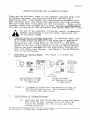
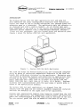
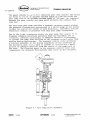
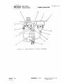
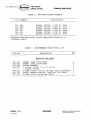
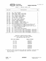
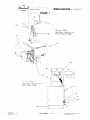
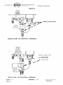
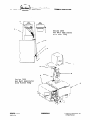
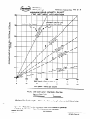
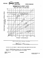
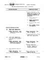
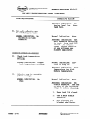
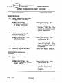
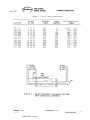
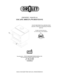
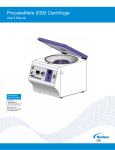
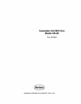
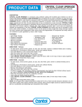
1
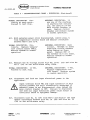
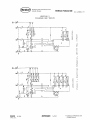
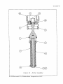
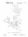
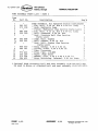
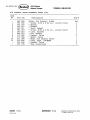
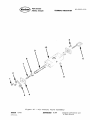
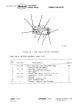
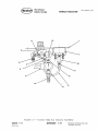
Hot Melt Applicators
Series 2000
Part104443A
NORDSON CORPORATION
l
AMHERST, OHIO
l
USA
SERVICES PROVIDED TO NORDSON CUSTOMERS
Customer Support Before And After The Sale
For more than 35 years Nordson has offered unparalleled service to its customers before, during
and after the sale. Nordson representatives will work with you to choose the best system for your
application. We’ll assist you during start-up and help train your employees to maintain and
operate the equipment. Plus, parts and service are only a phone call away from one of our
strategically located sales and service centers.
System Engineering
Custom designs and modification of standard equipment are available to meet your particular
needs. From a complete new system for automotive assembly to a special nozzle used in the
production of diapers, Nordson has the expertise to integrate adhesive and sealant equipment with
your manufacturing operation.
Parts And Accessories
In addition to standard replacement parts, many accessories are available to help improve
productivity and reduce downtime. For example, heated and non-heated in-line filters reduce
stoppages from clogged nozzles, and nozzles in multi-orifice, offset, right-angle and other designs
are available for special needs. Also, gloves, solvent, spare parts kits and other components are in
stock for immediate delivery. Conversion kits for tapers, labelers and box-forming equipment are
also available.
To help you eliminate downtime and costly inplant repairs, Nordson has developed a Rebuilt
Exchange (RBXsM)Program* which can save you up to 50 percent of the cost of new equipment.
You may trade in your old worn units, hoses and guns for rebuilt Nordson equipment which has
the same warranty as new equipment.
The Nordson Package of Valuesw
From specifications assistance to post-installation troubleshooting, the Nordson Package of Values
is designed to keep our customers productive and profitable by providing:
0
Carefully engineered,
0
Strong service support
0
The back-up of a well-established
0
A corporate commitment
durable products
international
company with financial and technical strength
to deliver what was specified
* This service not available in all countries.
306-l 8-662
ONORDSON CORPORATION 1993
All Rights Resewed
Issued 2193
770−497−3400
770−497−3400
3/05
US contact numbers updated 3/05
770−497−3500
770−497−3500
0
Nordson
P&A Division
Atlanta, Georgia
TECHNICALPUB1/CArlON
40-l-l
SAFETY SUMMARY
INTRODUCTION
Here you will find safety guidelines for the use of Nordson
equipment. These guidelines apply to anyone working with Nordson
equipment, including operations and service personnel. They are
repeated throughout this manual, along with specific warnings and
cautions not included in this section. These safety guidelines
cover:
l
Installation.
. Equipment operation.
l
Working with hot melt materials.
= Use of hot melt solvents.
Failure to follow these recommendations may result in personal
injury from burns or electrocution and/or equipment and property
damage.
EXPLANATION OF TERMS AND SYMBOLS
The following symbols are used in Nordson publications to alert the
reader to potential physical harm or equipment damage:
WARNING:
Failure to observe may cause
DEATH or PERSONAL INJURY
General
CAUTION:
Failure to observe can cause
DAMAGE TO EQUIPMENT
0
General
II
Electrical
A
c
Nozzle
3
Hot
A
e
A
0a*
l
Pressure'
Figure 1 - Nordson Corporation Safety Symbols
SUPERSEDES z/85
LITHO U.S.A.
8 NORDSON CORPORATION
All Rights Reserved
1986
TECHNICALPUl3L/CAllON
SAFETY DURING INSTALLATION
ELECTRICAL
A protective electrical ground connection to a reliable
earth.ground is essential for safe operation. Without one,
all accessible conductive components (including knobs and
controls that appear insulated) can render an electric shock.
A disconnect switch with lockout capability must be provided
between the power source and the equipment.
The power supply wire gauge and insulation must be sufficient
to meet the temperature and power requirements.
Only fuses of the correct type, voltage rating and current
rating should be used. Refer to the Nordson equipment parts
list for fuse recommendations. Using incorrect or nonrecommended fuses can present a fire hazard.
PNEUMATIC
Nordson recommends installing a lockout, three-way, manual valve in
the air supply line to the filter/regulator. This valve makes it
possible to relieve air pressure and lock out the pneumatic system
before undertaking maintenance or repairs.
GAS-SYSTEM (Pertains to FoamMelt
Kits Only)
@
Applicators and Nitrogen Blanket
Cylinders of compressed gas are under high pressure and can present
significant safety hazards if handled improperly. Refer to OSHA
General Industry Standards, paragraphs 1910.101, 1910.166 and 1910.167
for safety precautions that apply to the use, handling and storage
of compressed air.
SAFETY DURING OPERATION
Do NOT operate Nordson equipment under the following conditions:
= At a pressure higher than the rated maximum working pressure
of any component in the system.
= Near volatile or otherwise explosive gases or materials.
l
Without the covers, panels and safety guards properly
installed.
-
. At temperatures below 20° F (-6O C) or above 120° F (50° C).
ISSUED
LITHO U.S.A.
y/86
SUPERSEDES
2185
0 NORDSON CORPORATION
All Rights Reserved
1986
0
Nordson
-
P&A Division
Atlanta, Georgia
TECHNICALPUB1ICATION
40-l-3
With hoses enclosed in any material that interferes with
heat dissipation. This includes electrical conduit, insulation of any type or tight metal covers.
With large areas of hoses in contact with a cold floor, cold
supports or other such surfaces. Cold points along the hose
restrict the flow of adhesive inside the hose and can create
potential problems during operation.
(If outdoors or in drafty areas) with the applicator guns
unshielded from the wind. Rapid heat dissipation due to air
movement across the guns may cause operational problems.
With handgun trigger left unlocked while the gun is unattended.
In addition:
m Use only the metal base when attempting to lift or move this
equipment. Do not use equipment covers, doors, panels or
hose connectors as braces or grips.
. Never use this equipment as a ladder or stepping stool.
= Route all hoses so as to prevent damage from kinking,
abrasion and other physical damage. Do not allow a hose to
be installed with a bend radius of less than 6 inches
(150 mm).
m Never point an applicator handgun at yourself or anyone else.
SAFETY DURING SERVICING
m Do not perform internal service or adjustment on any equipment unless another person capable of rendering first aid
and resuscitation is present.
. Only qualified personnel should service Nordson equipment.
. To avoid personal injury, never touch exposed connections and
components while power is ON. Dangerous voltages exist at
several points in the equipment.
. Disconnect, lock out and tag external electrical power before
removing protective panels or replacing electrical components.
. Remove all jewelry (rings, watches, etc.) before servicing
equipment.
n
ISSUED
LITHO U.S.A.
If possible, stand on a rubber mat when servicing Nordson
equipment. Do not work on equipment if standing water is
present. Avoid working in a high-humidity atmosphere. Cover
exposed terminals and work area with rubber sheeting to avoid
accidental contact while the power is ON.
7/86
SUPERSEDES 2/85
Q NORDSON’CORPORATION
All Rights Reserved
1986
TECHNICALPUB1/CAT/ON
8 Always wear safety glasses, protective gloves (Nordson P/N
902 514 or equivalent) and long-sleeved protective clothing
to prevent injury from hot applicator parts, splashed hot
melt adhesive and hot gun surfaces,
-
= To prevent serious injury from molten adhesive under pressure,
always relieve system hydraulic pressure (by triggering the
handgun, for example) before opening any hydraulic fitting or
connection).
l
Never use an open torch, drill or broach when cleaning a
nozzle.
a Never continue to operate equipment with a known leak in the
system.
SAFETY WHEN‘USING HOT MELT ADHESIVES AND SOLVENTS
HOT MELT ADHESIVES
n
Use extreme care
solidify rapidly
Severe burns can
contact with the
still hot.
when working with molten materials. They
at high temperature and present a hazard.
occur if the molten materials come in
skin. Even when first solidified, they are
m Always wear protective clothing and eye protection when
handling molten material or working near equipment containing hot melt adhesives under pressure.
HEATING SOLVENTS
= Do NOT use an open flame or uncontrolled heating device to
heat solvents (for example, a small pan on an unregulated
hot plate).
Avoid fire hazard by using only a controlled heating device
to heat solvents (for example, a small deep fat fryer or
thermostatically controlled hot plate).
l
DO NOT USE PAINT-TYPE SOLVENTS UNDER ANY CIRCUMSTANCES!
These solvents are volatile and may create a fire and/or
toxic vapor hazard even at room temperature.
= Always be sure the work area is adequately ventilated.
Avoid prolonged or repeated breathing of solvent vapors.
ISSUED
LITHO U.S.A.
7/86
SUPERSEDES 2/8
5
‘i, NORDSON CORPORATION
All Rights Reserved
1986
0
Nordson
-
HALOGENATED
P&A Division
Atlanta, Georgia
HYDROCARBON
TECHNlCAl PUB1/CATION
40-l-5
SOLVENTS
Halogenated hydrocarbon solvents are dangerous when used to clean
aluminum components in a pressurized fluid system. No available
stabilizers prevent halogenated hydrocarbon solvents from reacting
under all conditions with aluminum components in a pressurized fluid
pumping system.
NEVER clean any aluminum component or flush any system using
halogenated hydrocarbon solvents. Use Type R solvents or contact
your solvent or hot melt supplier for a non-halogenated hydrocarbon
solvent for cleaning and flushing.
Halogenated fluids include the following solvents:
Fluorocarbon Solvents:
Dichlorofluoromethane
Trichlorofluoromethane
Chlorinated Solvents:
Carbon Tetrachloride
Chloroform
Dichloromethane
Ethylene Dichloride
Methylene Chloride
Monochlorobenzene
Monochlorotoluene
Orthodichlorobenzene
Perchloroethylene
Trichloroethylene
Brominated Solvents:
Ethylene Dibromide
Methyl Bromide
Methylene Chlorobromide
Iodinated Solvents:
Ethyl Iodide
Methyl Iodide
N-butyl Iodide
Propyl Iodide
IF MOLTEN MATERIAL COMES IN CONTACT WITH THE SKIN
n
Do NOT try to remove molten material from the skin.
. Immediately immerse the affected area in cold, clean water.
Keep the affected area immersed until the material has cooled.
. Do NOT try to remove the cooled material from the skin.
8 Cover the affected area with a clean wet compress.
= In cases of severe burns, look for signs of shock. If shock
is suspected, have patient lie down, use blankets to preserve
body heat and elevate the feet several inches.
. Call a physician immediately.
ISSUED
LITHO U.S.A.
7/a 6
SUPERSEDES 2/85
8 NORDSON CORPORATION
All Rights Reserved
1986
TECHNICAL PURLICATI~N
This page intentionally left blank.
--
/SSUED
LITHO U.S.A.
7/8 6
SUPERSEDES
2/85
Q NORDSON CORPORATION
All Rights Reserved
0
Nordson
Packaging
Atlanta,
and Assembly
Dlvlslon
TECHNICAL PfJBLICATlON
Georgia
APPENDIX
4 I- 2 O” ’ -Ao
A
RIGHT TO LEFT SIDE CONVERSION
SERIES 2000
ISSUED
LITHO
U.S.A.
9/ 84
SUPERSEDES
13/ 8 4
@ NORDSON
All Rghts
CORPORATION
Reserved
1984
0
Nordson
Packaging
Atlanta.
and Assembly
Dlvlslon
TECHNICAL PUBLICATION
Georgia
APPENDIX
4 1 - 2 ’ ’ ’ -A 1
A
RIGHT TO LEFT SIDE CONVERSION
SERIES 2000
INTRODUCTION
The Nordson Series 2000 hot melt applicators are shipped from the
factory with the manifold on the right side of the applicator
Because some applications require
as the standard configuration.
that hoses be routed from the left side of the applicator, a
conversion of temperature, electrical, and pneumatic controls must
be made.
To facilitate this conversion, the heat sink at the back
with the electrical and temperature
of the unit is interchangeable
controls.
The pneumatic control panel is also interchangeable
with
the information plate on the back of the unit.
Additionally,
the tank lid hinge can be relocated
will open to the left or to the right as required
tion.
The following paragraphs detail the conversion
the applicator to a left side unit.
PNEUMATIC
CONTRGL
such that the lid
by the applica-
procedure
to convert
PANEL RELOCATION
1.
Remove four screws and slide the pneumatic control panel out of
the applicator until the solenoid valve is exposed.
2.
Disconnect the pneumatic
valve connections.
7.
Unplug the electrical connector
connect wiring at TB2.
4.
Remove the information plate
by removing four screws.
5.
Slide the air control assembly into the back of the applicator
until the solenoid valve electrical connection can be plugged
into the coil or the wires can be connected at TB2.
6.
Attach
LITHO
9/84
U.S.A.
from the regulator
on the solenoid
and solenoid
coil or dis-
from the back of the applicator
hoses to the regulator
and solenoid
valve.
Attach the input hose to the solenoid valve and the output
hose to the regulator.
If the input hose is inadvertently connected to the regulator, no air will flow to the
air motor.
0
ISSUED
the pneumatic
hoses
SUPERSEDES
8/ 84
@ NORDSON
All Rights
CORPORATIO~Y
Reserved
1984
0
Nordson
41-200@-A2
Packaging
Atlanta,
and Assembly
Dlvwon
TECHNICAL PUB1 ICATlON
Georgia
7.
Slide the assembly all the way into the applicator
secure with four screws.
8.
Attach the information plate to the front of the applicator
base and secure with four screws.
ELECTRICAL
AND TEMPERATURE
CONTROL
1.
Remove the top electrical
screws.
2.
Remove
trical
3.
Carefully unplug
trol board.
4.
Cut and remove
NOTE:
PANEL RELOCATION
enclosure
by removing
the input terminal block support bracket
subplate by removing two screws.
the ribbon
base and
connector
three captive
from the elec-
from the temperature
con-
the red cable tie fro:m the wire harness.
Removal of this cable tie permits the temperature and
electrical control panel to be interchanged with the
heat sink panel without disturbing the main wiring
harness.
5.
Remove the electrical and temperature control
electrical subplate by removing two screws.
6.
Remove the main circuit
and lockwashers.
7.
Remove the heat sink assembly
by removing two screws.
8.
Secure the input terminal block support bracket to the suhplate
using two screws in the holes provid'ed between termiral block
TB2 and the front of the unit.
9.
Move the heat sink assembly panel to the front of the applicator and secure with two screws.
breaker
insulator
panel
10.
Attach the main circuit breaker
two screws and lockwashers.
11.
Attach the electrical and temperature
of the subplate using two screws.
12.
Secure the wire harness together
supplied with the applicator.
13.
Carefully plug
control board.
ISSUED
LITHO
U.S.A.
l/84
in the ribbon
from the
by removing
two screws
from the electrical
insulator
using
’ 3/83
subplate
to the subplate
control
connector
SUPERSEDES
panel
panel
the red cable
using
to the rear
tie
on the temperature
8 NORDSON
All Rights
CORPORATION
Reserved
1984
0
Nordson
0
14.
Packaging
Atlanta,
and Assembly
Dlvtslon
TECHNICAL PUBLICATION
Georgia
41-2000~A3/A4
Pins on the ribbon connector are easily broken and
Use caution not to push the plug onto the
bent.
board until all pins are aligned with the plug.
Carefully check that no wires are pinched under brackets
Check all terminal connections for
pulled too tightly.
tightness.
or
Pinched or broken wiring and loose electrical connections can cause erratic system operation, damage
to the equipment, and severe electrical shock.
15.
Install the top electrical enclosure
secure with three captive screws.
on the applicator'and
16.
Install the applicator
tion For Use.
with
ISSUED
LITHO
U.S.A.
I/ 8 4
in accordance
SUPERSEDES
3/83
Section
II, Prepara-
@ NORDSON
All Rights
CORPORATION
Reserved
1984
0
Nordson
Packaging
Atlanta,
and Assembly
Dlvlslon
TECHNICAl PUB1ICATlON 4 1- 2 o o o-n o
Georgia
APPENDIX
SERILS
lssUED 8 / 8 4
LITHO
U.S.A.
B
2000 PISTON-TO-GEAR
SUPERSEDES
PUMP CONVERSION
3/84
@ NORDSON
All Rights
CORPORATION
Reserved
1984
0
Nordson
P&A Division
Atlanta,
Georgia
TECHNICAL PUBLICATION
41-2000-B1
APPENDIX B
SERIES 2000 PISTON-TO-GEAR PUMP CONVERSION
The Series 2000 Piston-to-Gear Pump Kits (P/N 275 388 (2002/2004) and
275 384 (2202/2204)) include the parts required to convert a piston
pump Series 2000 applicator to an air-operated gear pump applicator
(See Parts List). To accomplish the conversion, refer to Figure 1
and follow this procedure:
1.
Check to be sure the adhesive in the tank is molten.
2.
Turn the main switch OFF and disconnect and lock out input
electrical power.
A
A
'I
The Series 2000 hot melt applicators contain energized
electrical components with potentials that could be fatal.
Disconnect and lock out input electrical power before
removing any panels.
e
Wear safety glasses, safety gloves (P/N 902 514), and
protective clothing to preve:nt injury from hot applicator
parts and surfaces.
3.
Remove the cover (1) and disconnect the air line connected to the
four Idayair valve (2).
4.
Remove the three M8 bolts (3) securing the pump to the unit and
remove the pump. Remove the strainer from the tank.
5.
Remove the FRP electrical enclosure (4) and tank enclosure (5).
6.
Mount the air motor and gear pump assembly (P/N 275 333) on the
unit. DO NOT insert the mounting bolts at this time.
7.
Attach the incoming air line to the port (6) on the air motor.
NOTE: Be sure the incoming air is connected to the port nearest
the tank.
NOTE: The air supply to the air motor must be lubricated.
8.
Mount the exhaust manifold (7) at the tapped holes in the base
using the screws (8) and lockwashers (9) provided. Attach the
muffler (13) to the manifold.
9.
Using the ell (10) and connector (11) as shown, connect the
copper tubing (12) to the muffler manifold and air motor.
10.
Insert the three M8 bolts removed in Step 4 through the mounting
plate on the gear pump assembly. Tighten the bolts. Place
the strainer included in the kit in the tank.
11.
Remove the four M5 screws securing the air control assembly (14)
to the front of the unit and pull the assembly out approximately
5 inches.
ISSUED2/86
LITHO
U.S.A.
SUPERSEDES
8/84
@ NORDSON
All
Rights
CORPORATION
Reserved
1986
PTFE
0
Nordson
Packaging
Atlanta,
and Assembly
Dwwon
TECHNKAL
Georgia
PUB1 /CAT/ON 4 i -
2
o
o
o
-
Series
2000
Hot Melt Applicatc,:
with Piston Pump
Series
2000
Hot Melt Applicator
with Gear Pump
ISSUED
LITHO
U.S.A.
8/ 84
SUPERSEDES
3/ 84
G NORDSON
CORPORATION
All Ftlghts Reserved
1984
.I33
41-2000+4
0
Nordson
PackagIng
Atlanta
and Assembly
Dlvlslon
TECHNICAL
Georgia
PUB1
/CAT/ON
FIGURE 2
REMOVE
PISTON PUMP AIR CONTROL
8/84
/SSOED
LITHO
U.S A.
PARTS
ASSEMBL.Y
‘ALL THESE
GEAR PUMP AIR CONTROL
THESE
PARTS
P/N
973
037
P/N
275
021
ASSEMBLY
SUPERSEDES
3/84
G NORDSON
All Rights
CORPORATION
Reserved
1984
Series 2000 Gear-to-Piston
Pump Conversion
Appendix C
EDB No. 41-2000
NORDSON CORPORATION.
AMHERST, OHIO.
USA
0
Nordson
SERIES
The Series 2000
and P/N 275 385
an air-operated
applicator
(See
to Figure 1 and
Packaging
Atlanta.
and Assembly
Dwlslon
Georgia
APPENDIX C
2000 GEAR-TO-PISTON
PWP
TECHNICAl PUB1/CAT/UN
4 1- 2 0 0 fi
-c 1
CONVERSION
Gear-to-Piston
Pump Kits (P/N 275 389 (2002/2004)
(2202/2204)) include the parts required to collT"Tert
gear pump Series 2000 applicator to a piston pump
Parts List).
To accomplish the conversion, refer
follow this procedure:
1.
Check
to be sure the adhesive
in the tank is molten.
2.
Turn the main switch OFF and disconnect
electrical power.
and lock out
ii?[Jut
The Series 2000 hot melt applicators contain eneryized
electrical components with potentials that could be
fatal.
Disconnect and lock out input electrical power
before removing any panels.
A
a
275
275
273
273
973
2
3.
Remove the cover (l), the FRP electrical enclosure
the tank enclosure (3) and disconnect the air line
to the gear pump air motor.
4.
Disconnect the copper tubing (5) from the muffler
by loosening the connector (7).
5.
Remove the three M8 bolts securing the pump to the unit and rt:move
the pump.
These bolts (8) are in the same locations that. trill be
used to mount the piston pump.
Remove the strainer from the tx:l:,
6.
Mount the piston pump assembly (P/N 273 141) on the unit.
Insert and tighten the three mounting bolts (8).
7.
Attach the incoming air line (9) to the four-way air valve (10)
using the reducer adapter (P/N 973 953) shipped with the kit.
8.
Place the new strainer
9.
Replace the cover, electrical enclosure, and tank enclosure
aKd restore the applicator to normal operation.
389
385
143
042
953
ISSUED
LITHO
Wear safety glasses, safety gloves (P/N 902 5141, and
protective clothing to prevent injury from hot applicator
parts and surfaces.
9/84
U.S.A.
(2), and
(4) connected
manifold
(6)
in the tank,,
Kit, Pump f Gear-to-Piston,
Kit, Pump f Gear-to-Piston,
a Strainer, Tank (with P/N
* Strainer, Tank (with P/N
O Adapter, Reducer
SUPERSEDES
2002/'2004
2202/'2204
275 389 only)
275 385 only)
Ref
Ref
1
1
1
@ NORDSON
All Rights
CORPORATION
Reserved
1984
41-2000-C2
0
Nordson
Packaging
Atlanta,
and Assembly
Division
TECHNICAL PUBf /CATION
Georgra
Series 2000
Hot Melt Applicator
with Gear Pump
Series 2000
Hot Melt Applicator
with Piston Pump
SUPERSEDES
@ NORDSON
All Rights
CORPORATION
Reserved
1984
--
0
Nordson
CORPORATlON
/ Amkst,
TECHATICAL
FU8LlCATlOAl 40-O-O
Ohio 44001
GENERAL
INFORMATjON
--
..
ISSUED
6/81
SUPERSEDES
4/ 7 9
9
C NCRDSON CORPOKATICN
I Rights Reserved
198I
0
Nordson
-
P&A Division
Atlanta,
Georgia
,NOMOGRAPH
MATERIAL
TECHNICAL
/CATION
REQUIRED
WIDTH
(INCHES)
‘-
.150
30
.lOO
.080
.020.
.060
I.040
.030
-.600
10
8
- 500
6
- ,400
4
3
.OlO
.008
.007
.006
= .200
.006
4-
.005
.8
.004
.6
.4
.003,
-
.3
.OOl
.0008
.002
.2
.0006
.lOO
.090
.oso
.070
- .060
.l
.08
.06
.0004
.0003
- .050
- -040
.O4
.oo 1
- .030
* NOMOGRAPH
BASED
I BEADS
A ROUNDED
WITH
VOLUME
ON
FLAT
TOP
POUNDS/
GALLON )
SPECIFIC
GRAVITY )
ISSUED 9J 1J70:
BEADS
m
SURFACE
a
REQUIRE
APPROXIMATELY
3s
SHOWN
POUNDS/CU.
LITHO U.S.A.
1.00
-900
- .800
- .700
20
,020
.OlO
.009
.008
’
PER 100 FEET
VOLUME*
(GAL)
(IN3)
.030-
THE
‘40-O-5
FOR HOT MELT BEADS
THICKNESS
(INCHES)
-
PUB1
7.0
7.5
8.0
8.5
9.0
9.5
IN. )
SUPERSEDES
Q NORDSON CORPORATION
All Rights Reserved
1986
0
Nordson
40-O-6
,
P&A Division
A Manta, Georgia
NOMOGRAPH
TECHNICAL
PUN
ICATION
FOR HOT MELT BEADS
METRK
Volume
(liters)
Thickness
(mm)
Q80
-
lo.0 4
0.70 -
s.0 -
0.60 -
Width
h-4
.
=20
1.0 -
QsoOAO-
QSy
0.30 -
Q.3-
30
-ls
L
-lo
0.20.20 =
0.l-
0.15 -
o.lo -
0.0s -,
0.04-
-4D
0.03 -
-3a
Qrn-
-
0.05 -
a
0.00s 0.004-
0.04 -
0.003 -
0.03 -
0.002 Material
*
52.0
L
0.017
0.06 -
5.0
-
15
.
-
LO
0.9
0.0
a7
required per 100 meters
Flat Bead
Rounded Bead
I .
B/;ljg
t I-A-l
1
T.
F=O.tM
F= 1.0
t
Volume in liters
= A x Bx F
kA-l
Weight in Kilogram
=
AxBxF
= Specific Gravity
10
10
EXAMPLE:
For a flat bead, 0.3 mm x 5.0 mm, with specific gravity of 0.9:
0.3x
volume = ,-
Weight
/SSUED
g/-l!70
CITHO U.S.A.
5.0x
0.3x5.0x
= ,lz)
1.0
=
1.0x0.9
.15 liten/
= 0.135
M
Gramr/lOO
M
SUPERSEDES
(B NORDSON CORPORATION
All Rights Reserved
1986
e&,,
P&A Division
A Manta, Georgia
TECHNICAL
PUBLICATION
40.om
MINIMUM BEAD LENGTH CHART
FOd HOi- MELT APPLICATION
0
100
I
I
0
20
200
Web
NOTE:
Gun Cycle
Speed
One
Length
400
- Feet per Minute
40
Web
Minimum
300
60
Speed
-
Gun Cycle
1
80
Inches per Second
= One Bead+
= 2 Times the Minimum
One Gap
Length
Curve B - #152670N
or dson Automatic Gun with Pneumatic
Curve A, C, D and E - Specific information not available
ISSUED g/1/70
SUPERSEDES
LITHO U.S.A.
500
shown at Left Side of chart
Operation
0 NORDSON CORPORATION
All Rights Reserved
1986
0
P&A Division
Atlanta,
Georgia
Nordson
40-O-8
TECHNICAL
PUB1
/CAT/ON
MINIMUM BEAD LENGTH CHART
FOR HOT MELT APPLICATION
.
14.0;
I
/
I, /
1
I
Minimum
Complete
/
I
/
Time for One
,
Gun Cycle
8.0
6.0
Web Speed - Centimeters/Second
NOTE:
Minimum
Gun Cycle
One
Gun Cycle
Length = 2 Times the Minimum
Curve B -- #152 670 Nordson Automatic
Curve A,
/SSUED
C,
:9/ lr’70
LITHO U.S.A.
= One Bead + One
D, and E - Specific
Length shown at left side of chart.
Gun with Pneumatic
information
Gap
_-
Operation
not available.
SUPERSEDES
0 NORDSON CORPORATION
All Rights Reserved
1986
0
Nordson
Packaging and Assembly
Atlanta, Georgia
Division
TECHNICAL
PUBfICATlUN
40-O-11
HOT MELT
FAULTS AND TROUBLESHOOTING CHART
The photographs below represent samples of bead faults commonly
encountered in the application of hot melt adhesives. Troubleshooting procedures are outlined on the pages that follow.
Cold Bead
Possible Causes:
A.
Adhesive colder than recommended application temperature.
B.
Ambient temperature in the
application area below
normal.
Example:
-
Ice cream plant
(cold draft blowing on nozzle)
c.
A stream of air directed at
guns and nozzles (radiation
and convection) will cool
the nozzle, gun, and adhesive.
D.
Gun thermostat not of the
proper temperature rating
for the material in use.
E.
The nozzle too far from
the substrate.
Excess Amount in Triggering
Possible Causes:
A.
Insufficient air pressure to
the gun.
B.
Insufficient air pressure
to the pump.
c.
The nozzle too far from
the substrate.
D.
ISSUED
9/81
Partially plugged nozzle.
SUPERSEDES
6/7
1
@
NORDSON
CORPORATION
All Rights Reserved
198 1
Packaging and Assembly
Atlanta, Georgia
40-O-12
Division
TECHNICAL
PUBLlCATlON
Stringing
Possible Causes:
A.
Adhesive too viscous.
B.
Cold adhesive.
c.
Lack of an air-piloted
relief valve between
solenoid and gun.
D.
Old adhesive (beyond
recommended pot life).
.
-s
-
L
Excessive Amount of Cut-off
Possible Causes:
A.
Insufficient air
pressure to the pump.
B.
Cold adhesive.
c.
Insufficient air
pressure to the gun.
-.
Concentric Circles
Possible Causes:
A.
Material too hot.
B.
Material low in
viscosity.
c.
High speed application (fast gun
cycling).
-
lSSUED 9,‘8
1
SUPERSEDES
6/ 71
LITHO U.S.A.
0
Nordson
-
Packaging and Assembly Division
Atlanta, Georgia
TECHNICAL
PUBL/CAT/ON
40-O-13
HOT MELT TROUBLESHOOTINGCHART
SYMPTOM/PROCEDURE
CORRECTIVE ACTION
Do not attempt to
loosen any part of
manifold, hose, or
gun system until air
to the unit has been
turned off and pressure has been relieved
from hot melt system
by triggering the guns.
Use safety goggles,
safety gloves (P/N
902 514), and protective clothing to
prevent injury from
splashed hot material
or hot parts.
ADHESIVE BOUNCES OR SPLASHES
FROM SUBSTRATE
Al.
Check adhesive temperature settings of applicator, hose and gun.
NORMAL INDICATION: Adhesive temperature settings normal.
Normal Indication: Proceed to step A2.
Abnormal Indication: Adhesive temperature too
high. Reduce temperature.
A2.
Check air pressure to
applicator.
NORMAL INDICATION: Air
pressure to applicator
within normal limits.
Normal Indication: Proteed to step A3.
.
Abnormal Indication: Applicator air pressure
too high. Reduce air
motor air pressure at
the regulator.
A3. Check adhesive viscosity.
NORMAL INDICATION: Adhesive visocity within
normal limits.
ISSUED 9/81
SUPERSEDES
Normal Indication: None.
6/7
1
0C
NORDSON CORPCRATION
All Rights Reserved
1981
( Nordson
a
40-O-14
Packaging and Assembly Division
Atlanta. Georgia
HOT MELT TROUBLESHOOTINGCHART (CONTINUED)
SYMPTOM/PROCEDURE
CORRECTIVE ACTION
Abnormal Indication: Adhesive viscosity too low.
Adjust one or more of the
following parameters as
necessary:
1. Reduce air motor
air pressure.
2.
Reduce application
temperature.
3.
Use lower flow-rated
nozzle.
4.
Use a higher viscosity adhesive.
ADHESIVE CHARRING IN TANK
Bl.
Check tank temperature.
NORMAL INDICATION: Tank
temperature within normal limits.
Normal Indication: Proceed to step B2.
Abnormal Indication: Tank
temperature too high. Reduce tank temperature.
B2. Check tank temperature
controller in accordance
with applicator service
manual.
NORMAL INDICATION: Tank
temperature controller
functioningproperly.
Normal Indication: Proteed to step B3.
Abnormal Indication:
Faulty temperature controller. Repair or
replace controller.
B3.
Check adhesive level in
tank.
NORMAL INDICATION: Tank
full of adhesive.
l&WED
9/81
SUPERSEDES
Normal Indication: Proteed to step B4.
6/7
1
LITHO
U.S.A.
0
Nordson
-
Packaging and Assembly Division
Atlanta. Georgia
TECHNICAL
PUBLICATION
40-O-15
HOT MELT TROUBLESHOOTINGCHART (CONTINUED)
SYMPTOM/PROCEDURE
CORRECTIVE ACTION
Abnormal Indication: Adhesive level low. Keep
tank full.
B4. Hot melt adhesive may
be oxidizing in tank.
NORMAL INDICATION: No
oxidation in tank
adhesive.
Normal Indication: None.
Abnormal Indication: Hot
melt adhesive oxidizing
in tank. Keep tank lid
closed. In extreme
cases, change adhesive
or use nitrogen gas
blanket applicator.
ADHESIVE FUMING OR SMOKING
Cl. Check tank temperature
setting.
-.
NORMAL INDICATION: Proper
tank temperature setting.
Normal Indication: Proceed to step C2.
Abnormal Indication: Tank
temperature too high.
Reduce temperature.
c2. Adhesive may be unstable
(chars easily).
NORMAL INDICATION: No
char.
Normal Indication: None
Abnormal Indication: Unstable adhesive. Use one
or more of the following
steps to reduce charring:
1. Keep tank lid closed.
2. Use a more stable
adhesive.
3. Use nitrogen gas
blanket applicator.
ISSUED
9/81
SUPERSEDES
40-o-16
0
Nordson
Packaging and Assembly Division
Atlanta. Georgia
TECHNICAL
PUB1
ICATION
HOT MELT TROUBLESHOOTINGCHART (CONTINUED)
SYMPTOM/PROCEDURE
CORRECTIVE ACTION
ADHESIVE JELLING
Dl.
Check temperature settingsof applicator and hose.
NORMAL INDICATION:
Temperature settings
in proper positions.
Normal Indication: Proceed to step D2.
Abnormal Indication: Overheating. Drain and flush
system in accordance with
applicator service manual.
Reduce temperature.
D2.
C!heckcompatibilityby
mixing adhesives in
separate container.
NORMAL INDICATION: Compatible mixture.
Normal Indication: Proceed to step D3.
Abnormal Indication: Incompatible mixing. Drain
and flush system in accordance with applicator service manual.
D3. Adhesive may be unstable.
Use a more stable adhesive.
ADHESIVE NOT PENETRATING
SUBSTRA,TE
El. Check adhesive temperature.
NORMAL INDICATION: Adhesive temperature within
normal limits.
Normal Indication: Proceed to step E2.
Abnormal Indication: Low
adhesive temperature.
Increase temperature
slightly.
/Ml/ED
9/81
SUPERSEDES
LITHO
U.S.A.
--
0
.
Nordson
-_
Packaging and Assembly Division
Atlanta, Georgia
TECHNICAL
PUBLICATION
40-O-17
HOT MELT TROUBLESHOOTINGCHART (CONTINUED)
SYMPTOM/PROCEDURE
CORRECTIVE ACTION
E2. Check substrate surface.
NORMAL INDICATION: No
coating on substrate.
Normal Indication: Check
with adhesive representative for a compatible
adhesive.
Abnormal Indication:
Coated substrate. Increase temperature slightlY* If adhesive still
does not penetrate, check
with adhesive representative for compatible adhesive.
NOTE: Flush and drain
system in accordance
with applicator service
manual before changing
adhesive.
E3. Check to see that adequate
amount of adhesive is being
applied to substrate.
NORMAL INDICATION: Adequate
amount of adhesive being
applied to substrate.
Normal Indication: Contact adhesive representative for a compatible
adhesive.
Abnormal Indication: Insufficient adhesive.
Use one or more of the
following steps to increase adhesive flow:
1. Use higher flowrated nozzle.
2.
Increase temperature slightly.
3.
Increase applicator air pressure.
.
ISSUED
9/81
C NORDSON CORPORATICN
II Rights Reserved
8
15’81
Nordson
40-O-18
0
Packaging and Assembly Division
Atlanta, Georgia
i
_
TECHNICAL
PUB1
/CA T/ON
HOT MELT TROUBLESHOOTINGCHART (CONTINUED)
SYMPTOM/PROCEDURE
4.
CORRECTIVE ACTION
Change adhesive to
another compatible
adhesive with lower
viscosity.
ADHESIVE STRINGING
Fl. Check gun position relative to substrate in accordance with 43-l.
NORMAL INDICATION: Proper height above substrate.
Normal Indication: Proceed to step F2.
Adnormal Indication: Gun
too far from substrate.
Move closer to substrate.
F2. Check adhesive temperature
and viscosity.
NORMAL INDICATION: Adhesive temperature and
viscosity within normal
limits.
Normal Indication: Proceed to step F3.
Abnormal Indication: Cold
adhesive .tooviscous.
Increase adhesive
temperature slightly.
Use lower viscosity
adhesive.
F3. Check adhesive shelf-life.
NORMAL INDICATION: Adhesive shelf-life recommended by adhesive manufacturer.
Normal Indication: Proceed to step F4.
Abnormal Indication: Drain
and flush old adhesive.
Add new adhesive to tank.
ISSUED
9/8*
SUPERSEDES
LITHO
U.S.A.
0
Nordson
--
Packaging and Assembly
Atlanta, Georgia
Division
..
TECHNICAL
PUBLICATION
40-O-19
HOT MELT TROUBLESHOOTING CHART (CONTINUED)
SYMPTOM/PROCEDURE
F4.
CORRECTIVE ACTION
Check for cold air blowing
on gun and/or low ambient
temperature:
NORMAL INDICATION: Normal
ambient temperature with
little air movement around
gun-
Normal Indication: Check
with adhesive manufacturer.
Abnormal Indication: Cold
air blowing on gun and/or
low ambient temperature.
Use one or more of the
following steps to correct the problem:
1.
Protect gun from
air movement.
2.
Increase adhesive
temperature slightly.
3.
Preheat substrate.
4.
Heat ambient air.
AIR IN ADHESIVE
Gl.
Check adhesive tank full
of molten adhesive.
NORMAL INDICATION: Adhesive tank full of
molten adhesive.
Normal Indication: Proceed to step G2.
Abnormal Indication: Adhesive melt tank empty.
Refill tank andoperate
guns until bubble disappears.
G2,
Check viscosity of adhesive.
NORMAL INDICATION: Adhesive viscosity within
normal limits.
ISSUED
9/81
SUPERSEDES
Normal Indication: See
MOISTURE BUBBLES IN ADHESIVE BEAD ON SUBSTRATE.
5/7 7
CORPCRATION
0CAll NORDSON
Rights Reserved
1981
Packaging and Assembly
Atlanta. Georgia
40-o-20
Division
‘TECHNICA
1 PUB1
/CA T/ON
-
HOT MELT TROUBLESHOOTING CHART (CONTINUED)
SYMPTOM/PROCEDURE
CORRECTIVE ACTION
Abnormal Indication: Increase adhesive temperature slightly or use a
lower viscosity adhesive
material.
DEPOSIT FROM NOZZLES UNEVEN IN
MULTI-GUN INSTALLATION
Hl.
Check for clogged nozzles
in accordance with gun
service manual.
NORMAL INDICATION: Adhesive flows freely
through nozzle.
Normal Indication: Proceed to step H2.
Abnormal Indication:
Clogged nozzles. Clean
nozzles in accordance
with gun service manual.
H2.
Check pressure drop across
guns and nozzles.
NORMAL INDICATION: Approximately equal pressure
(dropacross all guns.
ISSUED
-
9/81
SUPERSEDES
Normal Indication: None.
Abnormal Indication: Unequal pressure drop
across guns. Use one or
more of the following
steps to correct the
problem:
1.
Increase applicator
air pressure.
2.
Increase applicator
temperature slightly.
3.
Flush and clean guns
and nozzles.
4.
Use different flowrated nozzle or guns.
LITHO
U.S.A.
-
0
Nordson
Packaging and Assembly Division
Atlanta, Georgia
TECHNICAL
PUBLICATION
40-o-21
HOT MELT TROUBLESHOOTINGCHART (CONTINUED)
CORRECTIVE ACTION
SYT!'IPTOM/PROCEDURE
5. Use flow-control
valves in the lines.
GUN DROOLING
Il. Check gun needle and seat
for wear and/or char.
NORMAL INDICATION: Gun
needle and seat clean
with no indication of
wear.
Normal Indication: Proceed to step 12.
Abnormal Indication: Clean
and/or replace worn parts
in accordance with gun
service manual.
12. Check trigger adjustment
in accordance with gun
service manual.
NORMAL INDICATION: Trigger
adjustment within normal
limits.
Normal Indication: None.
Abnormal Indicator: Adjust trigger in accordance with gun service
manual.
MOISTURE BUBBLES IN ADHESIVE
BEAD ON SUBSTRATE
Jl. Apply adhesive to dry substrate and check for moisture bubbles.
NORMAL INDICATION: No bubbles on dry substrate.
Normal Indication: Dry
substrate prior to application of adhesive. Preheat substrate as necessary.
Abnormal Indication: See
AIR IN ADHESIVE.
lSSUE0
9/81
SUPERSEDES
NCRDSON
CORPORATICN
Rights Reserved
1981
Packaging and Assembly Division
Atlanta. Georgia
40-o-22
TECHNICAL
PUBLICATION
HOT MELT TROUBLESHOOTINGCHART (CONTINUED)
CORRECTIVE ACTION
SYMPTOM/PROCEDURE
CARTON POP-OPEN AFTER LEAVING
COMPRESSION SECTION
Kl.
Check adhesive not cooling
fast enough (too long an open time).
NORMAL INDICATION: Proper
open time.
Normal Indication: Proceed to step K3.
Abnormal Indication: Proceed to step K2 if open
time is too short. Use
one or more of the following steps if open time
is too long:
1. Decrease air pressure to air motor to
decrease bead size.
2. Reduce adhesive
temperature slightly.
3. Reduce line speed
through compression.
4. Move guns further
from substrate.
5.
Increase distance
from deposition to
compression.
6.
Increase compression
length.
7. Cool substrate.
8. Use lower flow-rated
nozzlei
9. Change bead pattern
from constant to
intermittent.
ISSUED
9/81
SUPfRSEDES
LITHO
U.S.A.
0
Nordson
-
Packaging and Assembly Division
Atlanta, Georgia
TECHNICAL
PUBLICATION
40-o-23
HOT MELT TROUBLESHOOTINGCHART (CONTINUED)
CORRECTIVE ACTION
SYMPTOM/PROCEDURE
10. Use adhesive with
shorter open time.
See adhesive manufacturer.
K2.
Check adhesive cooling
too fast (too short an
open time).
Normal Indication: Proceed to step K3.
NORMAL INDICATION: Proper open time.
Abnormal Indication: Use
one or more of the following steps to correct
the problem:
1.
Increase air pressure to air motor
to increase bead size.
2.
Increase adhesive
temperature slightlY*
3. Move guns closer
to substrate.
4.
Shorter distance
from deposition to
compression.
5. Heat substrate.
6. Use higher flowrated nozzle.
7.
Change bead pattern
from intermittent
to constant or increase bead length.
8. Protect deposit
and/or gun from
cold or moving air.
-
ISSUED
9/81
SUPERSEDES
ii/ij-
40-o-24
0
Nordson
Packaging and Assembly Division
Atlanta. Georgia
TECHNICAL
PUB1
/CATION
.
HOT MELT TROUBLESHOOTINGCHART (CONTINUED)
.,
SYMPTOM/PROCEDURE
CORRECTIVE ACTION
9. Use longer open time
adhesive. See adhesive manufacturer.
K3.
Check for sheared adhlesivedeposit.
NORMAL INDICATION: Adhesive deposit not
sheared.
ISSUED
9/81
SUPERSEDES
Normal Indication: None
Abnormal Indication:
Sheared adhesive deposit. Ensure substrate is not twisted,
jogged, or otherwise
subjected to adverse
movement in the compression section. See
adhesive manufacturer
if compression section
is smooth.
LITHO
U.S.A.
Hot Melt Hose
45-o-o
NORDSON CORPORATION.
AMHERST, OHIO.
USA
PTFE
PTFE
0
P&A Division
Nordson
45-3-30
TABLE
Length
ft 0-d
Part No.
272
274
272
274
272
274
272
274
272
274
273
274
063
323
838
324
839
325
840
326
841
327
624
320
2
2
4
4
6
6
8
8
10
10
16
16
Figure
ISSUED
5/8
TECHNICAL
A t/an ta, Georgia
(0.6)
(0.6)
(1.2)
(1.2)
(1.8)
(1.8)
(2.4)
(2.4)
(3.1)
(3.1)
(4.9)
(4.9)
1
-
HOSE
ELECTRICAL
Voltage
WC)
230
200
230
200
230
200
230
200
230
200
230
200
Power
(watts)
SUPERSEDES
Cold Resistance
WJW
47
52
100
104
153
156
206
208
267
260
420
416
l/84
1040
723
485
361
316
237
227
170
175
136
107
81
Publication No. 104 465A
-
1149
799
536
399
350
262
250
188
194
150
118
90
Hot Melt
ONORDSON
All
LITHO U.S.A.
/CATION
DATA
2 - Quick Disconnect Automatic
Hose Electrical Schematic
5
PUB1
Rights
CORPORATION
Reserved
1985
0
Nordson
PackagIng
Atlanta,
TABLE
and Assembly
Dwwon
YECHNICALPUBLICATION
Georgia
2 - PARTS LIST FOR FIGURE
Item No. Part No.
1
272 863
1
274 323
I
272 838
1
274 324
1
272 839
1
274 325
1
272 840
1
274 326
1
272 841
1
274 327
1
273 624
1
274 328
2
972 628
945 032
3
4
272 848
272 856
P39 528
ISSUED
LITHO
1 /8 4
U.S.A.
1
Description
Req'd
Automatic Hot Mel-t Hose,
w/Diode, 2 ft (0.6 m),
Quick Disconnect, 230 VAC
Automatic Hot Melt Hose,
2 ft (0.6 m), Quick
Disconnect, 200 VAC
Automatic Hot Mel-t Hose,
4 ft (1.2 m) I Quick
Disconnect, 230 VAC
Automatic Hot Melt Hose,
4 ft (1.2 m) , Quick
Disconnect, 200 VAC
Automatic Hot Melt Hose,
6 ft (1.8 m), Quick
Disconnect, 230 VAC
Automatic Hot Mel.% Hose,
6 ft (1.8 m) , Quick
Disconnect, 200 VAC
Automatic Hot Melt Hose,
8 ft (2.4 m), Quick
Disconnect, 230 VAC
Automatic Hot Melt Hose,
8 ft (3.4 m) , Quick
Disconnect, 230 VAC
Automatic Hot Melt Hose,
10 ft (3.1 mb, (!uick
Disconnect, 330 VAC
Automatic Hot Melt Hose,
10 ft (3.1 m), Quick
Disconnect, 200 VAC
Automatic Hot Melt Hose,
16 ft (4.9 m), Ouick
Pisconnect, 230 VAC
Automatic Hot Melt Hose,
16 ft (4.9 m) , Quick
Disconnect, 200 VAC
O Connector Assembly, Hose
O" O-ring, Viton, 0.38 in.
O" Connector, Male, g/16-18,
O-ring Boss
O Dustcover, Connector
O Receptacle, Connector
O Socket, Crimp Contact*
* A special tool to aid in removal and replacement
is available.
Order P/N
274 126.
Publication No. 104 465A
SUPERSEDES
4 5 - 3- 3 1
Ref
Ref
Ref
Ref
Ref
Ref
Ref
Ref
Ref
Pef
Ref
Ref
of crimp
@ NORDSON
All Rights
sockets
CORPORATION
Reserved
1984
0
Mordson
45-3-32
Packaging
Atlanta,
and Assembly
Division
TECHNICAL
Georgia
PUB1
ICATION
SERIES 2000 HOT MELT APPLICATORS
IN WATER WASH DOWN APPLICATIONS
A
Nordson Series 2000 hot melt applicators are not
designed for water wash down environments and
must be protected from hose directed water.
Water may enter unit.
Failure to follow these
instructions may result in electrical shock and
equipment damage.
A
Use the following guidelines to protect the applicator in the event
Series 2000 hot melt applicators are used in water wash down applications:
1.
Mount the applicator
pins areas.
2.
Route hoses and electrical conduit so water will not run down
the hose, hose cordset, or input electrical cable into the
applicator.
3.
Provide a metal. or plastic shield between the applicator
and any source of water spray or mist.
The shield should
not impair heat dissipation from the applicator or hoses.
ISSUED
LITHO U.S.A.
l/84
so that it is above any draining
Publication No. 104 465A
SUPERSEDES
@ NORDSON
All Rghts
or drip-
CORPORATION
Reserved
1984
Miscellaneous Technical
Data
Hot Melt
NORDSON CORPORATION.
AMHERST, OHIO.
USA
Nordson Corporation welcomes requests for information, comments and inquiries about its products
Address all correspondence to
Nordson Corporation
11475 Lakefield Drive
Duluth, GA 30136
Notice
This is a Nordson Corporation publication which is protected by copyright. Original copyright date 1981. No part
of this document may be photocopied, reproduced, or translated to another language without the prior written
consent of Nordson Corporation. The information contained in this publication is subject to change without notice.
Trademarks
AquaGuard, Blue Box, Control Coat, Equi=Bead, FloMelt, FoamMelt, FoamMix, Helix, Hot Shot, Hot Stitch,
Meltex, MicroSet, MultiScan, Nordson, the Nordson logo, OmniScan, Porous Coat, Posi-Stop, RBX, Sure-Bond,
ClniScan, UpTime, and Versa-Spray are registered trademarks of Nordson Corporation.
BetterBooksM, CF, Controlled Fiberization, Easy-Screen, Fibermelt, Flo-Tracker, PrintGuard, and Package of
Values are trademarks of Nordson Corporation.
Manual 59-O-O
Issued 9/81
Q 1981 Nordson CorporalIon
All Rights Reserved
0
Nordson
P&A Division
Atlanta, Georgia
TECWICAL
PUBLICATION
”
- ’ - 3
NORDSON TYPE R CLEANING SOLVENT
The flash point of Type R solvent is 550°F (288OC). Do
not heat this material above 475'F (246OC). Do not heat
Type R solvent with an open flame or in an uncontrolled
heating device (for example, a small pan or unregulated
hot plate). A fire hazard may exist if an open flame or
uncontrolled hot plate is used to heat Type R solvent.
A controlled heating device (such as a small deep fat
fryer or thermostatically controlled hot plate) should
be used to heat the solvent above the melting point of
the adhesive.
PHYSICAL PROPERTIES
Flash Point:
Freeze Point:
Vapor (Odor):
Color:
Viscosity:
Pounds/Gallon (kilograms/liter):
Molecular Weight:
Type R solvent meets the requirements
550°F (288OC)
32'F (OOC)
None
Clear
5,600 CPS @ 77'F (25OC)
9 (1)
3,300
Non-irritating to skin
Non-toxic
of the following FDA regulations:
175.105
175.300
175.380
175.390
176.170
176.180
177.1010
177.1210
USDA approved for use in food processing plants for cleaning hot melt
adhesive applicating equipment as long as there is no direct contact
with the food.
A
Do not take internally.
Keep out of reach of children.
USAGE
Type R solvent may not be compatible with all adhesives.
Before using Type R solvent with an adhesive for the
first time, test for compatibility using the procedure
described below.
0
NOTE:
ISSUE0
LITHO
2/8
U.S.A.
5
For ease of pouring, store Type R solvent at room
temperature 70°F (21OC). Do not store Type R solvent
at temperatures over 150°F (65OC).
SUPERSEDES
3/8
1
ONORDSON
All
Rights
CORPORATION
1885
Reclerved
Publication No. 104 708A
0
Nordson
59-l-4
USAGE,
Packagrng
Atlanta.
and Assembly
Owlston
TECHNICAL
Georgia
PUB1
ICATION
(Continued)
To clean parts exposed to hot melt, nozzles, and filters, soak the parts
in heated Type R solvent at a temperature
somewhat above the normal
adhesive application
temperature,
but less than 475°F (245°C).
When cleaning the AD-24 drop-in cartridge with Type R
solvent, do not submerge the entire cartridge in the
solvent. Be certain the pneumatic
section (top) of the
cartridge
is not inserted in the molten solvent. The
mixture of Type R solvent and molten adhesive will
cause the pneumatic
section to sieze.
0
If a question concerning
the compatibility
of Type R solvent and a
specific adhesive arises, consult the adhesive supplier or use the
following test:
1.
Hoat
the mixture
2.
Note
c:hanges in the mixture:
it:
FL
e.
slightly
above
the application
Discoloration.
Increase
in viscosity.
Gelling.
Separation of any ingredients
Sharp drop in viscosity.
temperature.
in the mixture.
Do not use Type R solvent when flushing equipment using
Polyamide,
Surlyn, Polyester or certain other high
performance
hot melt materials.
A gelled contaminant
may form which will cause nozzle plugging and charring
in the various heated components.
0
Before using a cleanout material other than Nordson Type
:? solvent, check to be sure the material meets these
specifications:
1.
2.
3.
4.
Non-toxic
and non-sensitizing.
Does not produce toxic vapors when heated.
Flash point at least 50°F (28OC) above intended
use temperature.
Non-corrosive.
Refer to the specific
information
regarding
Part
Nordson applicator
service
the use of Type R solvent.
No.
manual
for additional
Description
1
I
270 756
270 755
757
279
ISSUED
3!81
Solvent,
Solvent,
Solvent,
Type R, 5 Gallon (18.9 Liters)
Type R, 1
55 Gallon
Gallon (3.8
(208.2
Liters)
Type.R,
Liters)
SUPERSEDES
’ 2”76
LITHO
U.S A.
Publication No. 104 708A