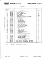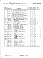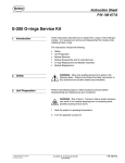
1
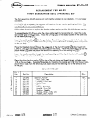
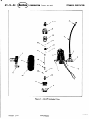
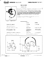
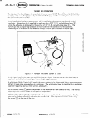
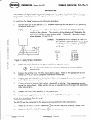
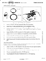
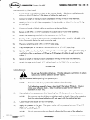
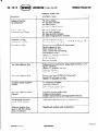
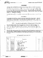
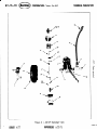
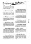
Model AD-29 w/F10 Valve
Part 104 453A
NORDSON CORPORATION
l
AMHERST, OHIO.
USA
42 -
I
0
NOrdSon
5- O O
CORPORATION
TEC#fU/CAl
/ Amherst. Ohio 44001
PUBLICATION
CONTENTS
42-15-1
Description
.
.
.
.
.
.
.
.
.
.
.
.
.
.
Specifications
.
.
.
.
.
.
.
.
.
.
.
.
.
.
-1
.
.
.
.
.
.
.
.
.
.
.
.
-2
.
.
.
.
.
.
.
.
.
.
.
.
-3
Operation
initial Start-Up
Shut Down .
Refilling
.
.
.
.
.
.
.
.
.
.
.
.
.
.
.
.
.
.
.
.
.
.
.
.
.
.
.
.
.
.
.
.
.
.
.
.
.
-5
-7
-7
Maintenance
Theory
of Operation
instal lation
Trouble
.
.
.
.
.
.
.
.
.
.
.
.
.
.
.
.
-7
Shooting
.
.
.
.
.
.
.
.
.
.
.
.
.
-8
.
.
.
.
.
.
.
.
.
.
.
.
.
-9
.
.
.
l
.
.
.
.
.
.
-9
.
.
.
.
.
.
.
.
.
.
.
-10
.
.
.
.
.
.
.
.
.
.
-11
Disassembl y
.
Recommended Spare Parts List
Exploded View
Parts List
- AD-29
.
.
.
.
LITHO
ISSUED
6/20/75
U.S.A.
0
NOrdson
CORPORATION
TECHNICAL
/ Amherst. O~HO44001
REPLACEMENT
FIRST
The first generation
available.
GENERATION
leather
If P/N 270 160 is ordered, the customer will
two packing kits are interchangeable.
receive
these directions
e AD-29
packing
SEAL
kit (with
Follow
AD-29
FOR
to replace
the leather
PUBLICATlON
(PACKING)
03
washers)
is now obsolete.
the new version
washer version
KIT
packing
It is no longer
packing
(seal)
kit with
the new version:
kit.
The
gun using the nylon washer
Place the O-ring
Q
0
in the body.
Use
these components
end of the shut-off
needle
on the clamp.
Place the
assembly with the
clamp 19 over the up
and thread the piston
the piston and
Insert
the needle assembly through the needle
appears at the extrusion end of the gun.
packing
until
-
the tip of the shut-off
needle
0
20
cylinder cover
into the gun body,
e extrusion end
SEAL
Fig.
,*
2 -159
AD-29
Thread the packing securely
Insert the needle packing 21 in the gun body.
a small amount of grease to ubricate the packing and needle before installing
in the gun body.
Place the threaded
(.040 to .070
piston washer
4
LITHO
U.S.A.
PARTS
LIST
1
Key
Part
No.
15
16
17
18
19
20
21
22
23
270
984
270
270
270
270
270
270
940
270
696
133
145
138
144
143
142
598
060
635
ISSUED
KIT
W8
Description
Qty.
SeaI Kit, AD-29
. Nut,
Lock, Hex
. Washer,
Piston Seal
. Seal, Piston
. Piston
. Clamp, Threaded
. Needle,
Shut-Off
Packing,
Needle
.
Viton,
l/8 x l/4
. O-ring,
Seal, Nylon
. Washer,
SUPERSEDES
s/77
Ref.
1
1
1
1
1
1
1
1
1
COPYRIGHT
3
1978 NORDSON
I
42-15-04
CORPORA
T/ON
TECHNICAL
/ Amherst, Ohio 44001
PUB1
/CA TlON
25
24
9
8
Figure
1 - AD-29
Exploded
View
LITHO
ISSUED
3/77
SUPERSEDES
U.S
0
Nordson
CORPORATION
TECHNICAL
/ Amherst. Ohio 44001
AD-29
4 2- 15 - 1
PUB1 /CATION
GUN
DESCRIPTION
The Nordson AD-29 Gun is designed to apply liquid resins (cold
glues) in a fine spray that will penetrate and harden on corrugated substrates much more rapidly than the extrusion
or wheel
By atomizing
the cold liquid adhetype cold adhesive systems.
sive into a spray the set time is reduced to a four (4)to six (6)
This short set time eliminates
the need for long
second range.
compression sections commonly required in cold glue applicat ions
Installation
of the AD-29
Gun is simple,
minimal,
and adhesive waste is slight.
Figure
1 - Model
Pressure
AD-29
Temperature
Operating
Air
Air
Pressure
Consumption
Air
Pressure
Electrical
Requirements
is
U.S.A.
METRIC
2 Gallons
7.56
Liters
Ambient
- Gun
40-60
- Gun
Operating
time
SPECIFICATIONS
Pot Capacity
Operating
clean-up
- Pressure
Pot
(Control)
PSI G
2 SCFM/Gun
Minimum
.944
lo-40
.7-2.8
PSIG
115 VAC,
50/60
kg/cm 2
2.8-4.2
Hz,
Litersbec.
kg/cm2
50 Watts
1.00”
25.4mm
t-l
LITHO
*
Figure
U.S.A.
1SSUED
4/77
1A - Mounting
SUPERSEDES
Dimensions
3/l 9176
COPYRIGHT
@
1977 NORDSON
I
4 2 - 15 - 2
0
Nordson
CORPORA TION / Amhersr. otvo
THEORY
The Nordson Pnu-Bond S
trol Lm , a Pressure Pot
the guns to the pot (or
TECHNICAL
44001
PUB1 ICATION
OF OPERATION
is comprised of one or more AD-29
Guns A , a Hot Stitch ConCl
a Special Model 25 Pump), and the necessary hoses to connect
In an installation
having a pressure pot, air is supplied to the pressure pot through a dual
regulator.
Atomozing
air is supplied to each gun by a 3/8” O.D.
polyethylen
hose @,
while the adhesive is delivered to the gun by a l/4” 0. D. polyethylene
hose E . The
AD-29 gun has a single high pressure orifice to deliver the adhesive to the subs6 rate.
Atomizing
air is directed to the adhesive through five air ports located in the air cap.
Figure
A multi-gun
installation
supply air and adhesive
2 - Nordson
Pnu-Bond
System
(1 Gun)
uses two manifolds (one on the air line and one on the fluid
to each gun from a single suppl y source.
line)
to
A solid-state
Stitch Control will permit the spray pattern to be interrupted
into a spray-gap-spray
The solid-state
timer is signalled by a customerpattern to keep glue consumption at a minimum.
supplied triggering
device (limit switch,
photocell).
An air control valve
F permits adjustment of the atomization
Cl
adjusting knob is color coded to aid specific adjustment.
from coarse to fine.
The valve’s
Adhesive flow rate is directly related to the air pressure applied to the pressure pot.
The flow
rate can be further refined by adjusting the needle ift.
This adjustment can be’made using
the screw G at the top of the gun.
0
/SSUED
1 l/2 l/75
LITHO
SUPERSEDES
@o/75
U.S.A.
0
Nordson
CORPORATION
/Amherst.
TECHNICAL
ohjo 44001
PUBLICATION
4
29 159 3
INSTALLATION
The Nordson Pnu-Bond System has several components that require installation
before the system
Installation
time will depend on the size of the system (how many guns are to be
can be used.
used).
To install
the Pnu -Bond System,use
the following
Position each gun to be used on a l/2”
the square head screw.
1.
NOTE
procedure:
diameter
mounting
The spray pattern width is directly proportional
to the distance from the
The viscosity of the adhesive wil I determine the
nozzle to the substrate.
ratio of gun height to spray pattern width.
Generally,
the ratio is somewhere between 1:l and 1:l .5.
:
An adhesive
will provide
An adhesive
may provide
1~1.5 ratio.
Example:
q
,
/
Id
?*
:‘A
3”
‘,
4”
/
\\
on the parent machine or separate stand.
Do not subject
temperatures .
the stitcher
to excessive
vibration
or extreme
ambient
Refer
Connect the stitcher to a 115 VAC input power supply.
instructions.
manual (57-4 or 57-12) f or complete installation
4.
Connect each gun solenoid to the stitcher.
or 57-12) for correct wiring information.
5.
Connect triggering device (limit switch,
photocell)
to stitcher.
(See appropriate service
manua I for instructions)
. Make certain the gun is grounded and wiring meets all applicable
code requirements.
6.
Connect
7.
Attach
the fluid
filter
an air supply
Gun
The AD-29
4.
3”
4”
3.
Single
LITHO
Control
of 1600 CPS
at a 1:l ratio.
of 500 CPS
closer to a
25.4 MM
50.8 MM
76.2 MM
101.6MM
2::
the Stitch
viscosity
pattern
viscosity
pattern
METRIC
1
\
0
with a
a spray
with a
a spray
U.S.A.
3 - Spray Pat tern D i mensions
Mount
2.
A
A
2” 3”
4”
\
/
Figure
bar and secure it by tightening
Installation
assembly
to the pressure
line to the inlet
(See Figure
must be connected
Refer
to the appropriate
manual (57-4
NPS
dual regulator
assembly.
4)
to the pressure
pot pneumatically
01
Attach
a l/4
NPS
x l/4
NPT
connector
2.
Secure
a l/4
NPT
x l/8
NPT
reducer
02
SUPERSEDES
and hydraulically.
to the dua I regulator
to the connector.
U.S.A.
11/21/75
service
service
pot.
side of the 3/8
1.
/SSUED
to the appropriate
b/20/75
assembly’s
output
side.
4 2 - I 5- 4
0
/ Amhersr,
Ohio
44001
CORPORATION
Nordson
INSTALLATICN,
TECHNICAL
/CATION
(Continued)
Figure
a l/8
NPT
4 - Typical
Gun
compression
Installation
Attach
4.
Secure the 3/8”
5.
Connect the black polyethylene
tube to the tee fitting 0 5 on the gun with
l/8 NPT x 3/8 Tube compression fitting . (Both straight and elbow fittings
Use either one.)
6.
Attach
3/8
NPS
x l/4
NPT
connector
7.
Secure
l/4
NPT
x l/8
NPT
reducer
8.
Install
9.
Secure the l/4”
10.
Attach
gun.
the l/8
x 3/8 Tube
Single
3.
Multi-Gun
PUB1
black polyethylene
NPT
x l/4
natural
fitting
tube @
@
07
the open end of the natural
to the reducer.
to the compression
to filter
fitting
tubing
@
polyethylene
fitting.
assembly on pressure
to the previously
Tube compression
polyethylene
@
installed
@on
another
are supplied.
pot.
connector.
the connector.
to the compression
fitting.
tubing
inlet
to the fluid
(6J
on the
Installation
Each gun must be connected pneumatically
installed on the air and fluid lines permits
and hydraulically
this to be done.
1.
Attach
2.
Install
3.
lnstal I a l/8
4.
Plug any unused manifold
5.
Plug the open port at the end of the manifold
L /ssum1 l/21/75
l/4
NPS
x l/4
NPT
connector
one of the two manifolds
NPT
x 3/8
to the output
supplied
T u b e compression
ports with
a l/8
SUPERSEDES
to the pressure
pot.
A manifold
side of the dual regulator
assembly.
on the connector.
in the manifold
NPT
for each gun to be used.
pipe plug.
with
a l/4
6/20/75
NPT
pipe plug.
LITHO
U.S.A.
0
Nordson
CORPORATION
INSTALLATION,
42
PUB1 ICATION
TECHNICAL
Ohio 44001
/Amherst.
- -5
15
(Continued)
6.
Cut the black polyethylene
tubing to the correct length.
(We have supplied
tubing to allow 10 feet or 3.04 meters of tubing for each gun.)
7.
Connect
8.
lnstal I a l/8 NPT
on each gun.
x 3/8 T u b e compression
9.
Connect
of black tubing
a length
of tubing
a length
NPS
x l/4
to each compression
NPT
fitting
fitting
in the air line
(straight
or elbow)
connector
to output
side of fluid
filter
Secure
a 3/8
11.
Attach
the remaining
12.
Starting at the port the furthest from the manifold
Tube compression fitting
for each gun to be used.
13.
Plug any remaining
14.
Plug the open port at the end of the manifold
15.
Cut the l/4” natural polyethylene
tubing to the correct length.
supplied to allow a maximum of 10 feet or 3.04 meters of tubing
system. )
16.
Secure
a length
17.
Attach
the open end of each l/4”
ports with
of tubing
manifold.
in the tee fitting
to each gun at the tee fitting.
10.
manifold
enough
to the connector
a l/8
NPT
on the filter.
fluid
inlet,
install
a l/8
NPT
x l/4
pipe plug.
to each compression
tubing
assembly.
with
a l/4
fitting
NPT
pipe plug.
in the fluid
length to the fluid
inlet
(Enough bulk tubing
to each gun in the
line
is
manifold.
on each gun.
OPERATION
Initial
Start-UpDo not use flammable adhesives.
Provide adequate ventilation
remove any harmful adhesive solvent vapors.
1.
Agitate
NOTE:
adhesive
before
pouring
For best results
to safe1 y
into pressure pot.
always
protect
the adhesive
from freezing.
Always
Cold adhesives general I y have a short she1 f I ife (about 90 days).
Refer to adhesive specification
sheet for
rotate your adhesive stock.
statement of shelf I ife.
2.
Pour adhesive
NOTE:
pot after
loosening
Close the pot and secure al I four (4) clamps.
4.
Apply air pressure to the ot.
PSIG (.7 and 2.8 kg/cm f )
The system works well
The air pressure to the pot directly
U.S.A.
ISSUED
6/2o/75
four (4) clamps and removing
cover.
The pressure pot should have a stainless steel or plastic liner or be coated so
that the water-based adhesive will not react with the galvanized
pot.
3.
NOTE:
LITHO
into pressure
SUPERSEDES
affects
at pressures
the flow
between
10 and 40
rate of the adhesive.
CCt’\r’3IG/-iT
‘5;
197,
NO?DSCN
0
Nordson
4 2- I 5- 6
OPERATION,
5.
Adjust
CORPORATION
PUB1 ICATION
(Continued)
air pressure
to the gun solenoid.
The gun works best at a air pressure setting
NOTE:
Figure
6.
TECHNICAL
/ Amhersr. otvo 44001
5 - Gun
of 55 PSIG
(3.87
kg/cm2).
Adjustments
Ad just atomizing
air . Close the air control valve (needle valve) by rotating the knob
Then open the valve two (2) full turns counter-clockwise.
For finer atomiclockwise.
zation turn the knob counter-clockwise;
for coarser atomization
turn the knob clockwise.
Each full turn of the needle valve knob provides
air at 55 PSIG (. 125 Liters/Set
at 3.87 kg/&).
NOTE:
The air flow valve
of
is color coded.
METRIC
U.S.A.
Green
Gold
Blue
Silver
about one (1) SCFM
.8 SCFM
1.8
2.8
4.6
@ 55 PSIG
.377
.85
1.32
2.17
Liters/Set
@ 3.87
kg/cm2
7.
Adjust the needle lift.
Close the needle adjustment screw by turning it clockwise until
it stops.
Al ways loosen the locknut before turning the screw.
Now open the needle lift
adjustment by turning the screw two (2) full turns counterclockwise.
If the flow rate needs
increase or decrease the pot (pump) pressure.
adjustment,
8.
Tighten
9.
Adjust
10.
The system is ready for use.
NOTE:
ISSUED
1 l/21/75
the needle
the Stitch
lift
locking
Control
nut.
(see the appropriate
Keep the system pressurized
or removing pressure lines.
SUPERSEDES
Stitcher
Service
unless opening
Manual).
and refilling
the pressure
pot
LITHO
6/20,‘75
U.S.A.
0
Nordson
CORPORATION
OPERATION,
42-15-7
TECHNICALPUBLICATION
Ohio 44001
(Continued)
the adhesive will not drain out of the fluid lines,
By keeping the system pressurized,
Keeping the fluid lines full will prevent adhesive residue from plugging the hoses
and guns.
NOTE:
1.
/Amherst,
Shut off Stitcher.
Start-Up
1.
Turn on Stitcher.
2.
If possible,
position
substrate
under (over) guns and fire
them a few times.
Refi I ling the Pressure Pot
1.
Shut off air pressure to pot.
2.
Open pot relief
A0
valve.
Do not loosen clamps unti I a I I pressure has been relieved.
+
&*
3.
Loosen four (4) clamps and remove pot cover.
4.
Agitate
5.
Pour fresh adhesive
fresh adhesive supply briefly.
into pot.
To keep the pot, fluid lines and guns clean it is a good idea to use a liner
in the pot. This liner can be alternated as the pot is refilled keeping
skimming of the pot at a minimum.
NOTE:
6.
Close the pot and secure the four (4) clamps.
7.
Turn on air pressure to the pot.
MAINTENANCE
A cold adhesive
leve Is.
system
requires
some daily
maintenance
to keep the system working
Use a soft wire probe (about
1.
Clean the air ports (4) in the air cap daily.
2.
Remove the air cap and clean the area around the nozzle
3.
Check the inline
4.
Do not allow
5.
Flush
iSSUED
6/20/75
adhesive
filter
at optimum
.025”
seat of all residual
diameter).
adhesive.
on a regular basis.
the inside walls of the pressure pot to skim over.
the hydraulic
part of the system regularly
SUPERSEDES
with warm water.
CGPYRIGHT
@
1975 NORDSON
TECHNICAL
TROUBLE
POSSIBLE
4dhesive flowing ,
10 atomization
F lo
Air
Air
Air
va Ive closed .
cap ports blocked.
hose kinked.
hose fittings blocked.
4dhesive flowing ,
atomization too coarse
Flo
Air
Air
Air
va Ive closed too far.
cap ports blocked.
hose partially blocked.
hose fittings partially blocked.
bidhesive flowing,
atomization too fine
Flo valve opened too far.
Gun air pressure too high (over 65 PSIG/4.57
No adhesive
Pressure pot not sufficiently
pressurized.
No air pressure to gun.
Stitch Control not “On”.
Stitch Control not functioning.
Gun solenoid failed.
Needle lift improperly adjusted.
Fluid line blocked.
Air line blocked.
Pressure pot empty.
CAUSE
adhesive
flow
Pressure pot not sufficiently
pressurized
kg/cm2 optimum).
Needle lift adjusted too low.
Fluid line blocked.
Fluid filter plugged.
Too much adhesive
flow
Pressure pot (over 45 PSIG/3.16
Needle I ift ad justed too high.
Too little
pattern
Air cap port(s) plugged.
Fluid seat blocked.
G lue dried on needle face.
Air cap orifice blocked.
Improper adhesive
(length)
pattern
Triggering device ma Ifunction.
Stitcher set incorrectly.
Stitcher ma Ifunctioning
(see appropriate
Piston
Adhesive leaking from
ports in AD-29 cylinder
cover or solenoid
Needle
seals need lubrication
kg/cm*)
(25 PSlG/l
.76
kg/cm2)
Improper adhesive
(width)
Air escaping from ports
in AD-29 air cylinder
cover
/CA T/ON
SHOOTING
‘ROBLEM
flow
PUB1
manua I).
or replacement.
seal washers need replacement.
LITHO
IS.WIFD
6/30/75
SUPERSEDES
U.S.A.
0
Nofdson
CORPORATTION
TECHNICAL
/ Amherst. Ohio 44001
PUBlICATION
42-15-g
DISASSEMBLY
gun is disassembled by
the extrusion end of the
the air cylinder cover
The needle packing
kit.
021
, O-ring
022
, and seal washer
23
0
are available
in the AD-29
seal
REASSEMBLY
Place the
AD-29 gun, insert the nylon seal washer 23 in the gun ody.
Q e packing
recess located at the lower end of the nee
21
.
Insert
the
6
Thread the needle packing securely in the gun body.
Use a
the gun body.
small amount of grease to lubricate the packing and needle as these parts are installed
in the
gun body.
NOTE:
Place the threaded
Be certain
clamp
the needle
packing
is tightened
over the upper end of the shut off
18 on the clamp.
Place the piston
and secure this assembly with the locking
the packing until the shut off needle tip
0
ly through
securely
in the gun body.
nut
end of the gun.
0
he air cylinder cover
11
into the gun body,
to the extrusion end
ot the gun.
RECOMMENDED
SPARE
PARTS
LIST
I
Fig.
6
Part
Key
270 696
984 133
15
16
270
145
138
20
21
22
23
9
270
270
270
270
270
940
270
270
143
142
598
060
635
152
10
270
151
17
18
19
LITHO
b
U.S
No.
144
Description
Req’d .
Seal Kit,
AD-29
. Nut, Lock, Hex, l/4-28
. Washer,
Piston Seal
. Seal, Piston
. Piston
. Cl amp, Threaded
. Needle,
Shut Off
. Packing,
Needle
. O-Ring,
Viton,
l/8 x l/4
Washer,
Seal, Nylon
Air Cap, AD-29
Nozzle/Seat,
AD-29
Ref.
1
1
1
1
1
1
1
1
1
1
1
A.
ISSUED
a/78
SUPERSEDES
4/n
COPYRIGHT
C\i 1978
NORDSON
42-15-10
CORPORA
Figure
ISSUED
4/77
T/ON
/ Amherst, Ohio 44001
6 - AD-29
SUPERSEDES
Exploded View
6/20/75
TECHNICAL
PUB1
/CATION
0
Nordson
CORPORATION
TECHNICAL
/ Amherst, Ohio 44001
PARTS
Fig.
1
901 015
2
3
4
5
6
7
973
973
900
971
973
901
270
270
i
9
000
250
509
154
125
091
137
153
270 152
10
11
270151
270
270
270
270
12
13
14
15
16
141
139
140
156
984133
17
270 145
270 138
18
19
270
270
20
270 142
144
143
21
270 598
22
23
24
940060
270 635
270150
25
28
.
: : Connector,
. Nameplate,l/8 AD-29
NPT x l/4
. . Plug, Pipe, l/8 NPTF
270157
.
148
405
534
511
See page 42-15-01
1
3
1
.75 Ft.
2
1
1
1
1
1
1
1
1
1
1
1
1
1
1
1
1
1
1
1
l
971 403
973 402
981
981
900
900
d/77
Req’d .
Gun, AD-29 w/Solenoid,Flo Valve
. Solenoid,
120 VAC
. Nipple,
l/8 NPT,
Close
. Tee, l/8 NPT
. Tubing,
l/4 O.D.
. Connector,
l/8 NPT x l/4 O.D.
Tube
. El bow, Street, l/8 NPT
Vy,lle,AFe;tle,
Flo Control
. .
:G
NLt,
Retaining
. . Air Cap, AD-29
. . Nozzle/Seat,
AD-29
. . Cover, Air Cylinder
. . Screw, Needle Stop
. . Nut, Locking
. . Spring, Piston Back-Up
. . Nut, Lock, Hex, l/4-28
. . Washer, Piston Seal
. . Seal, Piston
, . Piston
. . Clamp, Threaded
. . Needle,
Shut Off
. . Packing, Needle
. . O-Ring,
Vi ton, l/8 x l/4
. . Washer, Seal
. . Body, Gun w/Nameplate,
AD-29
Body, Gun, AD-29
.
ISSUED
LIST
Description
Part No.
270 136"
c
42-15-11
6
Key
*
PUBLICATION
1
1
1
Tube
.
Mounting,
Retainer
Screw, Fil.
Hd., lo-32 x l-1/4
Screw, Sq. Hd., 3/8-16
Tubing,
l/4 O.D,,
Polyethylene,
.040”
Tubing,
3/8 O.D.,
Polyethylene,
.062”
2
. .
. .
for INTERNATIONAL
MARKET
SUPERSEDES
1
Wall
Wall
part number.
11/21/75
COPYRIGHT @
I977 NORMON
42-15-12
co#Po#A
T/ON
/ Amherst, Ohio 44001
PNU-BOND
SYSTEM
PARTS
TECHNICALPUB1 /CA T/ON
LIST
Fig ./
Key
Part No.
F1-01
F1-02
F1-05
F1-03
Fl-06
2/D
270 136
244 528
900 511
240446
2/E
900 534
2/B
244 507
270 161
270 162
270163
270164
2/A
2/C
Description
Model AD-29,
One Gun Cold Adhesive
System, w/2 Gallon Pressure Pot
Model AD-29,
Two Gun Cold Adhesive
System, w/2 Gallon Pressure Pot
Model AD-29,
Th ree Gun Cold Adhesive
System w/2 Gallon Pressure Pot
Model AD-29,
Four Gun Cold Adhesive
System w/2 Gallon Pressure Pot
Model AD-29,
Five Gun Cold Adhesive
System w/2 Gal Ion Pressure Pot
. Gun, AD-29 w Solenoid, Flo Valve
. Pressure Pot w / Dual Regulators,2 Gal.
. Tubing,
Fi I ter Assembl
3/8 O.D.,
y
Polyethylene,
Black,
471
270 597
972
165
4/6
972 596
971 508
4/3
971 260
.062”
. Tubing, l/4 0. D., Polyethylene,
Natural, .040"
. Hot Stitch Control, CST-1,
115 VAC
. Kit, Installation,
One Gun
. Kit, Installation,
Two Gun
. Kit, Installation,
Three Gun
. Kit, Installation,
Four Gun
. Kit,
. Connector,
Installation, Swivel,
Five 3/8
Gun NPS x
l/4 NPT
. . Connector, Swivel,
l/4 NPT x
l/4 NPS
. . Connector, Elbow, l/8 NPT x
.
.
3/8 Tube
Connector,
Tube,
3/8 O.D.
971154
4/2
973 313
. . Connector, Male,
l/8 NPT
. . Reducer, l/4 NPT
270 159
973402
973410
971155
.
.
.
.
971 258
. . Connector,
l/4
O.D.
x l/8
Fl-
Fl-
Fl-
Fl-
02
05
03
06
1
1
1
1
1
1
1
10
1
2
1
20
1
3
1
30
1
4
1
40
1
5
1
50
1
Ft.
10
Ft.
1
Ft.
20
Ft.
1
Ft.
30
Ft.
1
Ft.
40
Ft.
1
Ft.
50
Ft.
1
1
1
1
1
1
1
1
1
1
1
1
1
1
1
1
2
3
4
5
x
2
4
6
8
8
x
1
2
3
4
4
2
4
2
2
2
2
2
2
l/8 NPT
4/8
Fl01
2
NPT
and 7
901 911
.
.
.
.
.
.
Manifold (Not shown)
Plug, Pipe, l/8 NPT
Plug, Pipe, l/4 NPTF
Connector,
Male, l/4
2
0. D. x
1
O.D.
1
l/4 NPT
l/8 NPT
Wrench,
Male,
Adjusting,
3/8
x
2
Module
2
2
2
2
LITHO
SllPFRCFncc
x/7,n/75
U.S A.