1
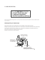
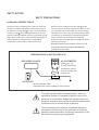
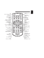
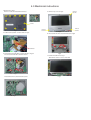
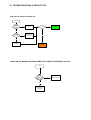
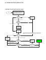
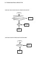
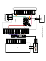
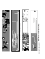
DVD Portable Player PET700/00/05/44/75 Service Manual TABLE OF CONTENTS Chapter Technical Specification…………………………………………1 Safety Instructions.……………………………………………...2 Instruction for Use.……………………………………………...3 Mechanical Instructions……………………………………….. 4 Troubleshooting & Service tips……………………………….5 Overall block diagram………………………….………...…... 6 Overall wiring diagram………………………………………… 7 Electrical diagram………………………………………………. 8 Component layout……………………………………………… 9 Service part list………………………………………………….10 Revision list………………………………………………………11 Copyright 2005 Philips Consumer Electronics B.V. Eindhoven, The Netherlands All rights reserved. No part of this publication may by reproduced, stored in a retrieval system or transmitted, in any form or by any means, electronics, mechanical, photocopying, or otherwise without the prior permission of Philips 3141 785 30561 Version 1.1 1.0 TECHNICAL SPECIFICATION and SERVICE HINT General Dimensions (WxLxH): Audio CD: Weight: Power supply: Power consumption: Operating temp. range: Laser wavelength: Video system: 19 x 14.6 x 2.9 cm 7.48 x 5.75 x 1.14 inches 1kg / 2.2 lb DC 9V 2.2A 20W 0 - 50°C (32 ~ 122°F) 650nm NTSC / PAL / AUTO Frequency response: 20Hz ~ 20KHz ± 1dB Signal/noise ratio: Audio distortion + noise: 85dB -80(1KHz) Channel separation: Dynamic range: 85dB 80dB Output Audio out (analog audio): Output level: 2V ± 10% Load impedance: 10K Video out Output level: 1Vp - p ± 20% Load impedance: 75 Current consumption DC-IN SUPPLY (9.0V) Battery Charging Current 1.2A typ. BATT. SUPPLY (7.2V) Power Off 0A Playback with TFT on <1.2A typ. Playback without TFT on <600mA Battery playtime >2.5hrs Headphone out (headphone output load 2x16ohm) Maximum output power: Frequency response: SNR (A-wght): THD (1kHz): Left-Right Channel Separation: Left-Right Channel Balance: Supported disc type DVD video discs: Video CD: >10mW 20Hz - 20kHz 80dB typ. <1% 32dB typ. 1dB In addition, this unit can play DVD+R & DVD+RW and CD-R & CD-RW that contains audio titles or MP3 or JPEG files. You cannot play disc other than the above listed. (CVD, CD-ROM, CD-Extra, CD-G and CD-I discs cannot be played on this DVD player) Software upgrades For the best performance of your DVD Portable. Check www.philips.com/support for latest software upgrades available. To check the software version of your DVD Portable. 1. Press the SETUP key to enter the setup menu. 2. Press RETURN and then press 1. 2 and 3 on the remote control. 3. The display will show the software version as the date of which the software was built on the bottom of the screen. E.g. 050303 Procedure on how to upgrade the software of the DVD Portable 1. Download the latest software from the Philips support site. 2. Unzipped the files and then burn it onto a CD ROM then playback the CD ROM on the DVD Portable. Pixel specification <= 4 (max. 0 bright dots and 3 dark dots) 2.0 SAFTETY INSTRUCTIONS GB NL ESD WARNING Alle IC’s en vele andere halfgeleiders zijn gevoelig voor electrostatische ontladingen (ESD). Onzorgvuldig behandelen tijdens reparatie kan de levensduur drastisch doen verminderen. Zorg ervoor dat u tijdens reparatie via een polsband met weerstand verbonden bent met hetzelfde potentiaal als de massa van het apparaat. Houd componenten en hulpmiddelen ook op ditzelfde potentiaal. All ICs and many other semi-conductors are susceptible to electrostatic discharges (ESD). Careless handling during repair can reduce life drastically. When repairing, make sure that you are connected with the same potential as the mass of the set via a wrist wrap with resistance. Keep components and tools also at this potential. F WAARSCHUWING ATTENTION I Tous les IC et beaucoup d’autres semi-conducteurs sont sensibles aux décharges statiques (ESD). Leur longévité pourrait être considérablement écourtée par le fait qu’aucune précaution n’est prise à leur manipulation. Lors de réparations, s’assurer de bien être relié au même potentiel que la masse de l’appareil et enfiler le bracelet serti d’une résistance de sécurité. Veiller à ce que les composants ainsi que les outils que l’on utilise soient également à ce potentiel. D AVVERTIMENTO WARNUNG Alle ICs und viele andere Halbleiter sind empfindlich gegenüber elektrostatischen Entladungen (ESD). Unsorgfältige Behandlung im Reparaturfall kan die Lebensdauer drastisch reduzieren. Veranlassen Sie, dass Sie im Reparaturfall über ein Pulsarmband mit Widerstand verbunden sind mit dem gleichen Potential wie die Masse des Gerätes. Bauteile und Hilfsmittel auch auf dieses gleiche Potential halten. Tutti IC e parecchi semi-conduttori sono sensibili alle scariche statiche (ESD). La loro longevità potrebbe essere fortemente ridatta in caso di non osservazione della più grande cauzione alla loro manipolazione. Durante le riparazioni occorre quindi essere collegato allo stesso potenziale che quello della massa dell’apparecchio tramite un braccialetto a resistenza. Assicurarsi che i componenti e anche gli utensili con quali si lavora siano anche a questo potenziale. GB Safety regulations require that the set be restored to its original condition and that parts which are identical with those specified, be used. “Pour votre sécurité, ces documents doivent être utilisés par des spécialistes agréés, seuls habilités à réparer votre appareil en panne”. NL Veiligheidsbepalingen vereisen, dat het apparaat bij reparatie in zijn oorspronkelijke toestand wordt teruggebracht en dat onderdelen, identiek aan de gespecificeerde, worden toegepast. CLASS 1 LASER PRODUCT 3122 110 03420 F Les normes de sécurité exigent que l’appareil soit remis à l’état d’origine et que soient utiliséés les piéces de rechange identiques à celles spécifiées. GB Warning ! Invisible laser radiation when open. Avoid direct exposure to beam. D Bei jeder Reparatur sind die geltenden Sicherheitsvorschriften zu beachten. Der Original zustand des Geräts darf nicht verändert werden; für Reparaturen sind Original-Ersatzteile zu verwenden. S Varning ! Osynlig laserstrålning när apparaten är öppnad och spärren är urkopplad. Betrakta ej strålen. SF Varoitus ! I Le norme di sicurezza esigono che l’apparecchio venga rimesso nelle condizioni originali e che siano utilizzati i pezzi di ricambio identici a quelli specificati. Avatussa laitteessa ja suojalukituksen ohitettaessa olet alttiina näkymättömälle laserisäteilylle. Älä katso säteeseen! DK Advarse ! "After servicing and before returning set to customer perform a leakage current measurement test from all exposed metal parts to earth ground to assure no shock hazard exist. The leakage current must not exceed 0.5mA." Usynlig laserstråling ved åbning når sikkerhedsafbrydere er ude af funktion. Undgå udsaettelse for stråling. 2.1 ESD PROTECTION Whenthepowersupplyisbeingturnedon,youmaynotremovethislasercautionslabel.Ifitremoves,radiationoflaser maybereceived. PREPARATIONOFSERVICING PickupHeadconsistsofalaserdiodethatisverysusceptibletoexternalstaticelectrocity. Althoughitoperatesproperlyafterreplacement,ifitwassubjecttoelectrostaticdischargeduringreplacement, itslifemightbeshortened.Whenreplacing,useaconductivemat,solderingironwithgroundwire,etc.to protectthelaserdiodeformdamagebystaticelectricity. Andalso,theLSIandICaresameasabove. Groundconductive wriststrapforbody. Solderingiron withgroundwire orceramictype 1M Conductivemat Thegroundresistance betweenthegroundline andthegroundislessthan10 SAFTY NOTICE SAFTY PRECAUTIONS LEAKAGE CURRENT CHECK Plug the AC line cord directly into a 120V AC outlet (do Measure the AC voltage across the 1500 resistor. not use an isolation transformer for this check). Use an The test must be conducted with the AC switch on and AC voltmeter, having 5000 per volt or more sensitivity. Connect a 1500 10W resistor,paralleled by a 0.15uF then repeated with the AC switch off. The AC voltage indicated by the meter may not exceed 0.3V.A reading 150V AC capacitor between a knomn good earth ground exceeding 0.3V indicates that a dangerous potential (water pipe, conduit, etc.) and all exposed metal parts of cabinet (antennas, handle bracket, metal cabinet screwheads, metal overlays, control shafts, etc.). exists, the fault must be located and corrected. Repeat the above test with the DVD VIDEO PLAYER power plug reversed. NEVER RETURN A DVD VIDEO PLAYER TO THE CUSTOMER WITHOUT TAKING NECESSARY CORRECTIVE ACTION. READING SHOULD NOT EXCEED 0.3V AC VOLTMETER DVD VIDEO PLAYER (5000 per volt or more sensitivity) 1500 10W AC OUTLET Good earth ground such as a water pipe, conduit, etc. 0.15uF 150V AC Test all exposed metal. Voltmeter Hook-up for Leakage Current Check The lightning flash with arrowhead symbol, within an equilateral triangle, is intended to alert the user to the presence of uninsulated "dangerous voltage" within the product's enclosure that may be of sufficient magnitude to constitute a risk of electric shock to persons. The exclamation point within an equilateral triangle is intended to alert the user to the presence of important operating and maintenance (servicing) instructions in the literature accompanying the appliance. English 3.0 INSTRUCTIONS FOR USE Front of player POWER / CHG Power and charging indicator Grip Opens display and disc tray OPEN CHG POWER Left of player POWER ON / OFF Switches the player on / off ON POWER OFF Right of player VOLUME VOLUME Volume control PHONES 1 & 2 Headphones jack AUDIO/VIDEO AV cable jack PHONE 1 PHONE 2 AUDIO/VIDEO TV OUT • •TFT ON COAXIAL DC IN 9V DC IN 9V Power supply socket COAXIAL Digital audio output jack (coaxial) TV OUT / TFT ON Selects video output English Disc tray FUNCTION Selects display mode 9/: For previous (ı 9 ) or next ( : ) chapters, tracks or titles OPEN Opens disc tray Disc tray Open to inser or remove disc , , , 5634 Up / down / left / right cursor OK Confirms selection TITLE Display TITLE page MENU Display MENU page OSD On Screen Display on / off PLAY Starts / resumes playback PAUSE Pause playback STOP Press twice to stop playback English Remote control OSD On Screen Display on / off LANGUAGE Language selector AUDIO Audio language selector SCAN Playback of the first 10 seconds of each chapter / index on the disc BOOKMARK Selects bookmark options MENU Displays MENU page TITLE Displays TITLE page SETUP Enters SETUP menu SUBTITLE Subtitle language selector ANGLE Selects DVD camera angle PLAY MODE Selects play order options ZOOM Enlarges / chapter / video image REPEAT Repeats chapter / title / disc A-B To repeat or loop a sequence in a title 9 Previous chapter, track or title : Next chapter, track or title 7 Search backward 8 Search forward PLAY / OK Confirms selection and starts playback STOP Press twice to stop playback PAUSE Pause playback 0-9 Numerical keypad , , , 5634 Up / down / left / right cursor SLOW PLAY Slow motion / Frame by frame playback RETURN For VCD menu page TIME SEARCH Searches by time MUTE Muting player volume 4.0 Mechnical instructions 1. Back View as Fig.1 Remove screws to Disassemble the base 5. Remove top cover as Fig.5 remove screws screws remove screws Fig.1 2. Soldered short pattern for laser diode as Fig.2 remove screws Fig.5 6. Disassemble the IF board and HV board as Fig.6 soldered Fig.2 3. Disassemble the DVD drive and main board as Fig.3,4 Disconnect the DVD drive and main board Fig.6 7. Detach the LCD TFT as Fig.7 Take off the screws to remove LCD TFT Fig.3 Disassemble the key board and other parts Fig.4 Fig.7 5.0 TROUBLESHOOTING & SERVICE TIPS 5.1 Procedure to change regioncode 1. Power on player and open DVD Door. 2. Press <Set Up> at Remote Control. In <Set Up Menu> select <Preferences>. 3. For PET700 - Press successively 2 5 2 3 1 5. . . 4. Display will show <Region Code 2> for Europe: 5. Press key to input preference region code (see below table). 6. Switch off and re-switch on the product. 7. Verify Region code change done. Region Code 1 2 3 4 5 6 Region USA EUROPE ASIA PACIFIC AUSTRALIA, NEW ZEALAND, LATAM RUSSIA, INDIA CHINA REMARKS: 1. Password is CONFIDENTIAL. 2. Region code is printed on product type plate. Due to DVD legislation region codes different to assigned region may not be released. 5.0 TROUBLESHOOTING & SERVICE TIPS SYMPTOM: NO POWER, NO GREEN LED start Check if the power cable and AC adapter OK? no replace cable/ adapter set OK? no replace connector and switch unit no yes No defect, return set to customer yes Check if the power and play button OK? yes replace MAIN BOARD go to other SYMPTOM SYMPTOM: NO IMAGE OR SOUND COMES OUT FROM THE EXTERNAL OUTPUT start Check operation of the DVD drive. Does the DVD drive work? yes Replace the main board or the connector no replace DVD drive 5.0 TROUBLESHOOTING & SERVICE TIPS SYMPTOM: THE INITIAL SCREEN IS NOT DISPLAYED ON THE LCD Refer to the symptom NO POWER, NO GREEN LED start Check if the LED on the front lights up? Replace broken harness no yes yes Check if the backlight is OK? Repair connector no Open the top and bottom assembly to check the connector harness Is the connector harness broken? no no Remove the LCD cover and plate of the LCD unit to check the connector of the FL harness Is the connector OK? yes Replace FL inverter or LCD yes Check if the lighting of the LCD is OK? no Open the top and bottom assembly to check the connector to the main board Is the connector broken? yes yes Replace LCD unit or main board Replace LCD harness or main board Connect the LCD harness to the LCD unit no Remove the LCD cover and plate of the LCD unit to check the connection of the harness to the LCD unit no Is the connection OK? yes Replace LCD unit or main board SYMPTOM: NO IMAGE OR SOUND COMES OUT FROM THE EXTERNAL INPUT start Replace the main board or the connector 5.0 TROUBLESHOOTING & SERVICE TIPS SYMPTOM: THE DVD DRIVE DOES NOT WORK Press the DISC cover switch at the center of the DVD player and turn on the power. Then check whether or not the optical pickup lens of the DVD drive lights. CAUTION: Visible laser radiation when open and interlock defeated. Do not stare into Laser beam. start yes Check the optical pick up lens? Replace DVD drive Pick up lens light up dim Pick up lens does not light up at all Check the connectors of the DVD drive and main board? OK Pick up lens light up OK Not OK Secure the connection of the DVD drive and main board Insert a DVD disc and turn on the power The DVD drive works but the initializing operation of the optical pick-up lens does not start (the optical pick-up lens operates twice), or abnormal noise sound DVD drive does not work Replace DVD drive or main board What is the reaction of the DVD drive? The operation of the DVD player stops at initializing display. Γoading?displayed Is there any message shown on display Γ HECK DISK?displayed Does the image output stop during the operation? DVD disc OK Check the DVD disc for fingerprints, dirt, No defect, return set to customer Nothing on display yes Is the DVD disc OK? no DVD disc dirty 5.0 TROUBLESHOOTING & SERVICE TIPS SYMPTOM: THE DVD DRIVE DOES NOT OPERATE WITH BATTERY start Install a good battery does the LED lights up orange while the AC adapter is connected and does the DVD drive operate OK? NOTE: - For this check, use a battery which is not fully charged (because the LED does not light when the battery is fully charged.) - Before this check, make sure other function work correctly. yes Replace battery no Is the connection of the battery OK inside the DVD player? no Secure the connection of the battery harness inside the DVD player yes Replace main board SYMPTOM: NO SOUND COMES FROM THE HEADPHONES start Insert a good headphones and check if the problem persist? yes Replace main board no CustomerΓ headphones defective 5.0 TROUBLESHOOTING & SERVICE TIPS SYMPTOM: NO SOUND COMES FROM THE HEADPHONES start Insert a good headphones and check if the problem persist? yes Replace main board no CustomerΓ headphones defective 110~240V 50/60Hz DRIVER (BA5954FP) KHM-252 PU mechanism AC Adapter DC IN +9V RF AMP D2891 TC4W53 +5V NT56V6620C0T-75S MX29LV008TTC-70 (BQ2057C) DC / DC (R1224) (TPS5100) DC / DC (R1224) DRIVER +5V +3.3V TFT POWER DC 9V R R L L +5V -14.5V +16V (VG202C) AUDIO D/A (PCM1742) UPD5100 BATTERY (TPC8207) AUDIO +/-5V AUDIO +5V R L 27MHz 74HCU04 27MHz SERVO & DVD PROCESSOR MPEG-2 DECODER & VIDEO ENCODER D2881 64M SDRAM 8M FlashROM 6.0 OVERALL BLOCK DIAGRAM SPEAKER AMP (D2822) PHONE AMP (NJM4580) AUDIO AMP (NJM4558) TFT MONITOR SPEAKER ROUT SPEAKER LOUT PHONE OUT AUDIO OUT S-VIDEO OUT VIDEO OUT DC 9V HIGH VOLTAGE ASS'Y 24 23 22 21 20 19 18 17 16 15 14 13 12 11 10 9 8 7 6 5 4 3 2 1 1 2 3 4 5 6 LIMIT GND SLSL+ SP+ SP- NC LD/VCC V20 GND F E CD/DVD SW RF C D B A VRCD VRDVD MD LD/CD GND LD/DVD NC VCC FCSTRK+ TRKFCS+ LOADING 24 23 22 21 20 19 18 XS5 17 16 15 14 13 12 11 10 9 8 7 6 5 4 3 2 1 1 2 3 4 XS401 5 6 SWITCH PCB XS403 XS001 MAIN PCB FUNCTION BUTTON PCB 1 2 3 4 5 6 7 8 9 10 11 12 13 14 15 16 17 18 19 20 1 2 3 4 5 6 XS6 7 8 9 10 11 12 13 14 15 16 17 18 19 20 1 GND 2 COMB 3 GND 4 -14.5V 5 GND 6 +16.5V 7 GND 8 GND IF PCB 9 3.3V 10 3.3V 11 GND 12 XS3 SPKR 13 GND 14 SPKL 15 GND 16 GND TFT ON/OFF 17 BRIGHT-CO 18 TFT-HV9V 19 TFT-HV9V 20 VCOMS GND 3.3V GND B G R GND MODE2 MODE1 SPOI SPIO SPS CLD NC CLS GND GND TFT +5V TFT +5V 30 29 28 27 26 25 24 23 22 21 20 19 18 17 XS1 16 15 14 13 12 11 10 9 8 7 6 5 4 3 2 1 1 XS4 2 3 4 7.0 Overall wiring diagram XS4 XS3 1 2 3 4 5 6 7 8 9 10 11 12 13 14 15 16 17 18 19 20 GND GND ISEN VSEN VCOMS TFT-16V SPIO NC NC CLD MODE1 GND VDD1 GND SPOI GND LCD R LCD G LCD B TFT5V TFT5V GND GND TFT+13V COMS GND GND MODE2 CLS SPS VDD1 GND VDD3V3 VDD3V3 1 2 3 4 30 29 28 27 26 25 24 23 22 21 20 19 18 17 16 15 14 13 12 11 10 9 8 7 6 5 4 3 2 1 HV POWER PCB 1 2 3 4 GND GND ISEN VSEN LCD 1 2 3 4 1 GND POWERSW 2 DCIN 3 1 2 3 1 2 3 4 5 6 7 8 KEYIN3 KEYIN2 KEYIN1 KEYIN0 KEYOUT0 KEYOUT1 KEYOUT2 KEYOUT3 1 2 3 4 5 6 7 8 S 3 G 4 6 D 5 D N019 G 2 7 D TPC8207 S 1 8 D C031 100N R059 1M R033 56K R034 39K R001 0.075 DC IN +9V 1K 4 VM 3 CO 2 DO ICT 6 VC 7 VSS 5 N018 1 SENS BQ2057C C055 220N C053 220N VD206 LED CHRG R002 1K R056 1K R036 56K VR002 5K 1K R057 C032 100n C054 220N R035 56K Littelfuse 451005 F 5A/125V F002 SRF96E t t t IP405B217S VD016 ISS355 C005 100n TFT ON/OFF PTC PTC C057 100n OUT 3 4 3 2 1 R016 47K XS003 C080 10U/16V C079 10U/16V VD015 2SD601AR C010 100n R012 10 C008 100n R009 10 L009 LQH4N100J04 R010 10K C003 16V/100U N013 PQ05DZ11 R011 4.7K VD045 KTA1298 1 IN R088 47K R087 10K R017 4.7K R005 10K XS002 VD010 ISS355 VD011 ISS355 R007 1K VD014 2SD601AR R008 10K VD009 UDZS7E-1715B R006 47K VD013 UDZS7E-174.7B VD001 UPA1716G VD032 LED R052 2K VD033 U5FWK24C42 R003 47K SW003 ESD1062 VD004 RB060L-40 VD003 RB060L-40 VD028 2SJ401 3 2 R218 1K R032 1K VD002 IN5402T VCC 8 STAT 5 4 TS R058 1K R055 VSS 6 N020 CC 7 3 VCC COMP 8 2 BAT 1 SNS R030 100K R031 120K FM001 LV902 POWER SWITCH T3A/1 25V S8232AUFT 1 N001 R1224N N003 IR7304 N004 R1224N 1 IN C078 100n C014 NC VD017 RB060-40L VD018 RB060-40L N5 BA033 OUT 3 C077 10U/16V R018 2.7K 1 IN R050 3K OUT 3 D4 LT1117-1V8 R014 2.7K C021 100u/16V C012 1000P C076 100n R015 20K R013 91K R047 0.25 C020 100u/16V L002 CDRH6D38-330MC R020 20K C018 1000P R019 56K L001 CDRH6D38-330MC L016 BGH2012B601LT N003 IR7304 1 Littelfuse 1 CE F001 452003 2 GND 2 JS001 HEC4801-010110 3 VIN 5 CE 1 VIN 5 GND 2 VOUT EXT 4 3 VOUT EXT 4 3 1 IN C015 100n 1 IN CB108 100n 1 IN N005 BA033 OUT 3 R049 1K C15 10U/16V 1 7 6 5 C046 470P CB81 100n 8 2 3 4 POWER ON/OFF N014 NJM2360 C18 10U/16V C14 10U/16V CB05 100n C016 100n CB6 100n C461 100U/6V C493 10U/16V C498 100U/6V C417 10U/16V C412 10U/16V C424 10U/16V C17 10U/16V L3 BGH2012B601LT C048 100U/16v CB10 100n CB01 100n CB25 100n CB82 100n CB06 100n CB32 100n CB16 100n c081 100n CB43 100n C049 100U/16v C316 L008 100U/6V LQH4N101J04 L305 BGH2012B601LT L413 BGH2012B601LT L408 BGH2012B601LT L430 BGH2012B601LT L420 BGH2012B601LT CB3 100n c099 100U/16V L017 BGH2012B601LT L005 CDRH6D38-330MC L419 BGH2012B601LT VD040 CRG01 CB14 100n VD031A RB040L L007 LQH4N101J04 C050 100U/6V C022 100U/6V C011 10U/16V L7 BGH2012B601LT N015 PQ05DZ11 OUT 3 OUT 3 N006 UPC29M05 GND cation: REPLACE PUSE WITH SAME TYPE AND RATING 4 2 DC POWER CIRCUIT DIAGRAM CO 2 GND 5 NC 4 GND 2 GND 2 CO 2 GND 5 8.0 ELECTRICAL DIAGRAM GND 2 NC 4 TFT +1.8V TFT +3.3V TFT +5V AUDIO -5V VIDEO +5V AUDIO +5V RVCCIN +5V +P5V AV33 DV33 V25 HV VCC L404 10uH VD404 2SB1132 LDO2 R421 0.5 + V1P4 C401 100uF/ 16v RVCCIN + CB11 0.1uF CB21 0.1uF CB12 0.1uF CB24 0.1uF D A CB23 0.1uF C418 D 1uF C419DD C 1uF CC AA B C420 1uF BB A C421 1uF AA CC B C DRVCC5V R430 20K C442 150p 65 66 67 68 69 70 71 72 73 74 75 76 77 78 79 80 81 82 83 84 85 86 87 88 89 90 91 92 93 94 95 96 97 98 99 100 101 102 CB25 0.1uF AGNDF VCON AVDDF AGNDX AVDDM COSPHI HALLCOS REFCOS AGNDM HALLSIN REFSIN SINPHI SW0 SW2 SW1 MOP MON AGNDX AGNDX CEON CEOP RFGCI RFGCU RFFGC OSP OSN CDD CDC CDB CDA DVDRFIN DVDRFIP DVDD DVDC DVDB DVDA MA MB C430 47uF/ 16v RVCCIN S2 PLAY SCLK + S3 TOPMENU CB3 0.1uF N401 D2890 CB39 0.1uF CB37 0.1uF R530 100 R529 100 R526 1K C427 0.015uF CB36 0.1uF S4 MONITOR S10 DOWN S15 QUICK S16 UP VR1 WHXB-2-20K C512 10uF/ 16V VD509 2SD601AR VFO13 VDD AGNDX AGNDX AGNDX DPFO DPFN GNDP HTRC TRLP TRLPA CRTPLP CRTP HRFRP LRFRP DEFECT VDDP TEO CSO LVL FEO V20 VREFO V2REFO AVDDT TM4 AGNDT TM3 TM2 TM1 AGNDO RFON RFOP AVDDO AGNDX AGNDX WVDD WOBSO 38 37 36 35 34 33 32 31 30 29 28 27 26 25 24 23 22 21 20 19 18 17 16 15 14 13 12 11 10 9 8 7 6 5 4 3 2 1 IR RFVCC R545 100K R530 10K R543 100K R406 0 BDO CB20 0.1uF + C493 47uF/ 16v N406 HSB0038 R540 10K R541 10K R529 10K C485 47U/ 6V R407 10K R401 10 +P5V C515 10uF C514 10uF C513 10uF/ 16V 1 1 1 1 CB98 0.1uF C406 CB29 0.1uF TEO CSO RFL FEO V20 V1P4 V2P8 CB02 0.1uF RVCCIN CB35 0.1uF 390p C404 10pF C405 390p C407 470p C403 0.01U R411 100k R410 27k C402 27p C499 C408 0.033uF CB86 TP11 TEO TP12 CSO TP13 RFL TP15 FEO CB26 CB27 C415 10uF/ 10v 1 LPFOP 1 JITFO 1 LPFIP C444 47uF/ 16v TP29 C452 100pF C456 330pF 25 26 27 28 32 33 34 35 RESET 10 RY/ BY 12 VCC 30 VCC 31 23 VSS 39 VSS 11 NC 29 NC D0 D1 D2 D3 D4 D5 D6 D7 C457 0.015uF TP30 TP31 CB46 0.1uF A0 A1 A2 A3 A4 A5 A6 A7 A8 A9 A10 A11 A12 A13 A14 A15 A16 A17 A18 A19 A20 CE OE WE VD512 STZ6.2N RFRP HTRC CB41 0.1uF C446 1uF C450 0.01uF C448 0.01uF R440 20k R442 18k V33 R445 15k R409 0 R443 TP34 0 R444 10k CB52 0.1uF C455 330pF VD513 STZ6.2N AUDIO VCC C575 C576 100uF/ 16V 100n C556 100U C542 100U L502 100UH C530 100n AD0 AD1 AD2 AD3 AD4 AD5 AD6 AD7 RFON RFOP 0.1uF + 10uF/ 10v 21 20 19 18 17 16 15 14 8 7 36 6 5 4 3 2 1 40 13 37 38 22 24 9 + 7 VCC-5V N412 MX29LV008TTC-70 SMD TSOP-40(10x20mm) VCC+5V 100uF/ 16V C540 C544 51P L-OUT VCC 8 GND 4 1 R-OUT C545 51P C445 100pF 0.1uF 0.1uF R544 5.1K FCE# PRD# PWR# A0 A1 A2 A3 A4 A5 A6 A7 A8 A9 A10 A11 A12 A13 A14 A15 A16 A17 A18 A19 V1P4 DMSO FMSO PWMOUT2 FOSO TRSO R432 4.7 AV33 RVCCIN N502 4580 6 IN3 IN+ 5 IN+ 2 INR547 5.1K + C538 100U/ 16V C536 100U/ 16V RFRPC V1P4 HTRC V2P8 RFON RFOP C447 0.01uF CB27 0.1uF CB26 0.1uF C439 1000pF R414 100k R416 R R415 0 C415 10uF/ 16v C495 10uF/ 16v TP18 1 1 TP22 RFIN IREF PLLVSS LPIOP LPION LPFON LPFIP LPFIN LPFOP JITFO JITFN PLLVDD3 FOO TRO TROPENPWM PWMOUT1 PWMOUT2 DVDD2 DMO FMO DVSS FG HIGHA0 HIGHA1 HIGHA2 HIGHA3 HIGHA4 HIGHA5 DVSS HIGHA6 HIGHA7 AD7 AD6 AD5 AD4 DVDD3 AD3 AD2 AD1 AD0 IOA0 IOA1 DVDD2 IOA2 IOA3 IOA4 IOA5 IOA6 IOA7 A16 A17 IOA18 IOA19 IOA20 APLLVSS RFIP AV33 R417 18k + R464 4.7K R463 4.7K CB91 0.1uF SW002 AUX SW SW001 CLOSESW N413 24C01 C476 10uF/ 16v R462 39k VD413 ISS355 N509 + DV33 C473 5.1P D2871 SMD LQFP-216 1 1 D409A 74HC04 2 2 G401 C27MHz R405 1M C472 1000P Y2 Crystal : DIP +SMD C466 TZC03A-200P CB73 0.1uF C474 20p R305 180 R303 180 R304 180 + 4 C311 20p L303 1UH L301 1UH L416-L436 BSZ2012-600T CB54 0.1uF L409 10 C315 100uF/ 16v C313 100uF/ 16v + + CB10 0.1uF C316 100uF/ 16v 1 MUTE VCC 16 2 INA OUTA1 15 3 GND OUTA2 14 4 INB OUTB1 13 5 GND OUTB2 12 + C425 10uF/ 16V L410 BGH2012B601LT N301 BA7660FS 6 NC DTC2 11 7 INC OUTC1 10 8 GND OUTC2 9 CB102 0.1uF XTALI C471 C CB104 0.1uF L437-L448 BSZ2012-600T R453 AV33 4.7 SD33 L305 100UH C320 100uF/ 6V C321 100uF/ 6V C317 100uF/ 16v R305 18 VIDEO 5V R315 10 R306 10 C319 47U/ 4V C318 47U/ 4V C314 47U/ 4V DI CLK CS PAL/ NTSC DISPLAY1 DISPLAY0 TFTON/O FF NC BATDET SW003 TFT SW JP2 TO KEYBODY 1 2 3 4 5 6 7 8 L425 BGH2012B601LT CB101 0.1uF 0.1uF CB15 0.1uF CB16 0.1uF CB17 0.1uF CB18 CB5 0.1uF CB6 0.1uF CB7 0.1uF CB8 0.1uF CB9 0.1uF CB10 0.1uF CB19 TO TFT BOARD CB14 0.1uF DV33 0.1uF EM407 FK2125T186AL CB4 0.1uF V25 VREF 1 DACV33C R583 ASDAT4 2.2k TP28 ASDAT3 ASDAT2 ASDAT1 ASDAT0 ASPDIF AMDAT ACLK DV33 ALRCK ABCK DQ16 KEYIN0 DQ17 KEYIN1 GND DQ18 KEYIN2 DQ19 KEYIN3 DQ20 KEYOUT0 DQ21 KEYOUT1 V25 DQ22 KEYOUT2 DQ23 KEYOUT3 DQM2 DQM3 GND DQ24 TFTSW DQ25 BATDET DQ26 NC DQ27 TFTON/O FF DV33 DQ28 DISPLAY0 DQ29 DISPLAY1 DQ30 PAL/ NTSC DQ31 CS GND MA3 MA2 MA1 MA0 V25 MA10 BA1 DQM0 DQM1 GND MA4 MA5 TFT SW MA6 DV33 MA7 Y0 C312 100uF/ 16v 162 161 160 159 158 157 156 155 154 153 152 151 150 149 148 147 146 145 144 143 142 141 140 139 138 137 136 135 134 133 132 131 130 129 128 127 126 125 124 123 122 121 120 119 118 117 116 115 114 113 112 111 110 109 C428 10uF/ 16V YUV0/ CIN FS VREF DACVDDC ASDATA4 ASDATA3 ASDATA2 ASDATA1 ASDATA0 SPDIF MC_DATA ACLK DVDD3 ALRCK ABCK RD16 RD17 DVSS RD18 RD19 RD20 RD21 DVDD2 RD22 RD23 DQM2 DQM3 DVSS RD24 RD25 RD26 RD27 DVDD3 RD28 RD29 RD30 RD31 DVSS RA3 RA2 RA1 RA0 DVDD2 RA10 BA1 DQM0 DQM1 DVSS RA4 RA5 RA6 DVDD3 RA7 DMVSS C308 20p L302 1UH C304 20p 74HC04 D409B V33 3 C467 100uF/ 6V N419 ESMT M12L64164A-? SMD TSOP(II)-54D400x875mil 8.0 ELECTRICAL DIAGRAM MAIN BOARD CIRCUIT DIAGRAM CLOSE AUX C495 100uF/ 6V DV33 CB107 0.1uF 1 2 3 4 5 6 7 8 9 10 11 12 13 14 15 16 17 18 19 20 21 22 23 24 25 26 27 28 29 30 31 32 33 34 35 36 37 38 39 40 41 42 43 44 45 46 47 48 49 50 51 52 53 54 C437 1000pF RFDTSLVN RFDTSLVP C449 0.01uF R433 8.2k C451 0.01uF R438 750k V25 R452 4.7 DV33 GND GND V25 1 PWMOUT1 A8 A9 A10 A11 A12 A13 A14 A15 AD7 AD6 AD5 AD4 AD3 AD2 AD1 AD0 A0 A1 A2 A3 A4 A5 A6 A7 A16 A17 A18 A19 A20 AV33 JS504 AUDIO OUT JS502 HEAD PHONES JS503 HEAD PHONES LS1 SPEAKER + FOSO CD/DVD SW C443 100U/ 16V S1 LEFT S8 RETURN S13 PREV S9 STOP S5 RIGHT S11 NEXT VCCI C508 10uF VCCI -5v C509 10uF S6 NC R515 10K 1 S14 PAUSE S7 NC +5v C574 100n C518 300P 2 3 5 N501A 4558 S12 MENU R593 10 + R514 3.9K R517 10K C516 3n R521 3.9K C573 100uF/ 16V R516 100K R513 5.6K 7 N501B 4558 C531 100U/ 16V 1 VCC 2 3 GND 4 L-OUT R-OUT + C411 47uF/ 16v LDO1 LDO_AVCC C401 47uF/ 16v N403 TC4W53 + 14 13 12 11 10 9 8 7 6 5 4 3 2 1 R465 33 C554 10uF C555 10uF 6 R520 10K C519 300P R508 150K N503 2822 6 IN-L 7 IN-R 5 IN8 IN- + 1 R413 10 VNFFC VOSL VINSLVINSL+ CF2 CF1 VINFC JP2 KEYBODY 16 MC 14 MD 13 12 ML 15 SCK 8 7 6 5 4 3 2 1 G1 29 VOFC+ VOFCVOSL+ VOSLPGND PVCC1 VCC + AVCC5V L430 10uH V20 L407 10uH VD406 2SB1132 1 DRVCC5V N402 BA5954FP PREGND VINLD CTK2 CTK1 VINTK BIAS STBY 15 16 VOTK+ VOTK17 VOLD+ 18 19 VOLDPGND 20 VNFTK 21 PVCC2 30 G2 22 23 24 25 26 27 28 CB42 0.1uF + CB84 0.1uF N417 PCM1742 1 BCK 2 DATA 3 LRCK 4 DGND 5 +3.3V ZERONA 6 +5V 8 ZERO OA 11 LOUT 7 ROUT VCC5V R511 10K R522 100K R507 150K + + + CB31 0.1uF FMSO TRSO V1P4 STBY C414 100uF/ 16v R494 33 VD411 ISS355 10 VCOM 9 GND R556 1K R519 5.6K C517 3n R527 1K C534 47U + + + + + + C497 100uF/ 16v A 24 23 22 21 20 19 18 17 16 15 14 13 12 11 10 9 8 7 6 5 4 3 2 1 VD410 ISS355 DRVCC5V DRVCC DRVCC LIMIT SLED+ SLED+ SLEDSLED- DMSO ECR FG FR GND GND CB40 0.1uF + SL+ SL- R419 0.5 XS401 SF-HD8C HEADER 24SMD0.5 TOP C441 150p R429 20k XS402 TO SPM0TOR 14 13 12 11 10 9 8 7 6 5 4 3 2 1 AUDIO 5V CB01 0.1uF CB22 0.1uF R558 10K V20 VD524 KTA1298 VD522 ISS355 VD510 2SD601AR C532 3n3 LS2 SPEAKER VSS VSS VSS 54 41 28 NC NC 36 40 DQML DQMH 15 39 + 14 7 VCC 114 VCC 27 VCC VCCQ 93 VCCQ 43 VCCQ 49 VCCQ VSSQ 612 VSSQ 46 VSSQ 52 VSSQ 19 18 17 16 DQM0 DQM1 CS RAS CAS WE DCS# DRAS# DCAS# DWE# A 14 7 RN419 22 7 R559 VD505 2SD601AR 4.7K R567 0 C525 3n3 C535 47U TP25 Y7 1 1 CLK CKE 38 37 + R521 10K C511 220U/ 10V R509 10K XTALI SDCLK SDCKE C487 10uF/ 16V R557 1K + R510 10K TP26 VSYNC# Y6 Y5 GND Y4 DACV33A Y3 GND Y2 DACV33B Y1 GND HSYNC# TP24 1 DV33 SPBCK SPLRCK V25 SPDATA SPMCLK HSYNC# GND Y7 VSYNC# BLANK# DQ0 DQ1 DQ2 DQ3 DQ4 DQ5 DQ6 DQ7 DQ8 DQ9 DQ10 DQ11 DQ12 DQ13 DQ14 DQ15 2 4 5 7 8 10 11 13 42 44 45 47 48 50 51 53 DQ0 DQ1 DQ2 DQ3 DQ4 DQ5 DQ6 DQ7 DQ8 DQ9 DQ10 DQ11 DQ12 DQ13 DQ14 DQ15 A0 A1 A2 A3 A4 A5 A6 A7 A8 A9 A10/AP A11 BA0/A13 BA1/A12 VDD 8 VEE 3 VSS 4 CH1 5 COM 1 INH 2 CH2 6 VD407 KTA1298 DV33 IR V25 RXD TXD UWR# URD# GND DQ7 DQ6 DQ5 DQ4 V25 DQ3 DQ2 DQ1 DQ0 WE# CAS# RAS# CS# BA0 GND DQ15 DQ14 DQ13 DQ12 DV33 DQ11 DQ10 DQ9 DQ8 GND DCLK DCKE MA11 MA9 MA8 23 24 25 26 29 30 31 32 33 34 22 35 20 21 VD525 ISS355 VD526 ISS355 VD523 ISS355 VD521 ISS355 R560 470 URST GND CB33 0.1uF ADIN TP19 1 ADIN GND BDO SCLK SDEN SDATA RFRP C426 1000pF RESETAV MUTE FG FR MDI2 MDI1 LDO1 LDO2 RFL FEO CSO TEO SCL DV33 SDA P3.0 SCL SDA A0 VDD 87 A1 NC 6 A2 SCL 5 A3 SDA CD/DVD SW ASTB STBY LIMIT F E RFZC RFRPC VSCK VSDA PWMOUT2 URST SDATA SDEN 64 63 62 61 60 59 58 57 56 55 54 53 52 51 50 49 48 47 46 45 44 43 42 41 40 39 AVDDP AGNDX AGNDP DPDMUTE RST SDATA SDEN GNDS SCLK XCK16M VDDS IOB IOA IO9 IO8 IO7 IO6 IO5 IO4 IO3 IO2 IO1 IO0 HDGATE UDGATE GND MC MD SA SB AGND IR AVDD SC SD CDFOP CDFON SVDD TPI TNI SGND WGAND AGC1 WAVDD AGC2 AGC3 MDI2 MDI1 LDO1 LDO2 RFSUBO WGND 103 104 105 106 107 108 109 110 111 112 113 114 115 116 117 118 119 120 121 122 123 124 125 126 127 128 R425 33k 216 215 214 213 212 211 210 209 208 207 206 205 204 203 202 201 200 199 198 197 196 195 194 193 192 191 190 189 188 187 186 185 184 183 182 181 180 179 178 177 176 175 174 173 172 171 170 169 168 167 166 165 164 163 ALE PRD# PWR# PCE# GND VCC GND RMC 1 2 3 RFIP RFIN RFDTSLVN RFDTSLVP ADCVDD3 PWM2VREF PWMVREF HRFZC RFRP_AC RFRP_DC RFLEVEL FEI CSO TEI TEZISLV RFSUBI ADIN ADCVSS BDO SLCK SDEN SDATA WOBSI UDGATE DVDD3 IDGATE VFO13 DVSS PRST XTALI XTALO DVDD3 SPBCK SPLRCK DVDD2 SPDATA SPMCLK HSYN DVSS YUV7 VSYN BLANK# ICE YUV6/R YUV5/B DACVSSA YUV4/G DACVDDA YUV3/CVBS DACVSSB YUV2/Y DACVDDB YUV1/C DACVSSC APLLVDD3 ALE IOOE# IOWR# IOCS# DVSS UP1_2 UP1_3 UP1_4 UP1_5 UP1_6 DVDD3 UP1_7 UP3_0 UP3_1 INT0# IR DVDD2 UP3_4 UP3_5 UWR# URD# DVSS RD7 RD6 RD5 RD4 DVDD2 RD3 RD2 RD1 RD0 RWE# CAS# RAS# RCS# BA0 DVSS RD15 RD14 RD13 RD12 DVDD3 RD11 RD10 RD9 RD8 DVSS CLK CLE RA11 RA9 RA8 DMVDD3 1 2 3 4 + + 55 56 57 58 59 60 61 62 63 64 65 66 67 68 69 70 71 72 73 74 75 76 77 78 79 80 81 82 83 84 85 86 87 88 89 90 91 92 93 94 95 96 97 98 99 100 101 102 103 104 105 106 107 108 MA0 MA1 MA2 MA3 MA4 MA5 MA6 MA7 MA8 MA9 MA10 MA11 DBA0 DBA1 C460 100uF/ 16v + + MUTE VCC5V R568 100K C510 47U/ 6V + 8 4 2 3 3 2 TOP VD301 STZ6.2N JS501 VIDEO OUT TO TFT Y TO TFT C DV33 9.0 COMPONENT LAYOUT DVD1650H HV PCB BOARD DIAGRAM DVD1731T-AS IF PCB BOARD DIAGRAM PET700 MAIN BOARD DIAGRAM 10. SERVICE PART LIST Service parts list on PET700 Service 12NC Model 994000000722 PET700 Accessory description BATTERY 994000002875 PET700 IF PCB ASS'Y 994000002876 PET700 MAIN PCB ASS'Y 994000002877 PET700 994000002878 PET700 FUNCTION PCB ASS'Y HV PCB ASS'Y 994000002879 PET700 TFT LCD 994000000724 PET700 REMOTE CONTROL 9940000002891PET700 20 PIN HARNESS (LE105) 994000002892 PET700 20 PIN HARNESS (L140) Photo 10. SERVICE PART LIST 994000000726 PET700 AV CABLE 994000002893 PET700 SPEAKER 994000000727 PET700 994000002894 PET700 TRAVEL BAG DV23 LOADER 994000000725 PET700/00/05/44CAR CIGARTTE ADAPTOR 994000000728 PET700/05 ADPV18A ADAPTOR /05 994000000723 PET700/00 ADPV18A ADAPTOR /00 994000002897 PET700/44 ADPV18A ADAPTOR /44 994000002156 PET700/75 ADPV18A ADAPTOR /75 10. SERVICE PART LIST 994000002881 PET700 TOP COVER 994000002882 PET700 DISPLAY FRAME 994000002883 PET700 MIDDLE CABINET 994000002884 PET700 994000002885 PET700 BOTTOM CABINET BASE COVER 994000002886 PET700 DOOR 994000002988 PET700 CONTROL KEY PAD 994000002895 PET700 994000002887 PET700 994000002888 PET700 DOOR SPRING OPEN BUTTON SPRING TOP COVER LOCK SPRING 11.0 REVISION LIST Version 1.0 (3141 785 30560) Initial release PET700/00/05/44/75 Version 1.1 (3141 785 30561) Chapter 10: Service parts list adapted with new parts and revised 12NC as listed below • Added photo on speaker (994000002893) • Deleted DVD mark (994000002889) • Added the new part control key pad (994000002988)