1
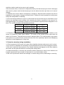
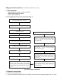
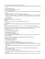
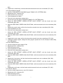
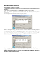
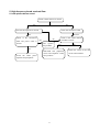
FILE NO.
SERVICE MANUAL
LCD-47XR2
LCD TV
PRODUCT CODE No.
1 682 342 81 : AUS, SS etc.
1 682 343 78 : INDIA
REFERENCE No.:SM0915013
CONTENTS
Safety Precautions………………………………………………………………………..…1
Alignment instructions. ………………………………….…………………………….…
3
Software upgrade method…………………………………………….…………………… 8
Working principle analysis of the unit……………………..……………………….…… 9
Block diagram……………………………………………………………………………… 11
IC block diagram……………………………………………………………..……………. 12
Wiring diagram……………………………………………………………………………..…24
Troubleshooting………………………………………………………..…………….……. 25
Schematic diagram…………………………………………………………………………..33
APPENDIX-A: Assembly list
APPENDIX-B: Exploded view
Attention: This service manual is only for service personnel to take reference with. Before
servicing please read the following points carefully.
Safety precautions
1. Instructions
Be sure to switch off the power supply before replacing or welding any components
or
inserting/plugging in connection wire Anti static measures to be taken (throughout the entire
production process!):
a) Do not touch here and there by hand at will;
b) Be sure to use anti static electric iron;
c) It’s a must for the welder to wear anti static gloves.
Please refer to the detailed list before replacing components that have special safety requirements.
Do not change the specs and type at will.
2. Points for attention in servicing of LCD
2.1 Screens are different from one model to another and therefore not interchangeable. Be sure to
use the screen of the original model for replacement.
2.2 The operation voltage of LCD screen is 700-825V. Be sure to take proper measures in
protecting yourself and the machine when testing the system in the course of normal operation or
right after the power is switched off. Please do not touch the circuit or the metal part of the module
that is in operation mode. Relevant operation is possible only one minute after the power is
switched off.
2.3 Do not use any adapter that is not identical with the TV set. Otherwise it will cause fire or
damage to the set.
2.4 Never operate the set or do any installation work in bad environment such as wet bathroom,
laundry, kitchen, or nearby fire source, heating equipment and devices or exposure to sunlight etc.
Otherwise bad effect will result.
2.5 If any foreign substance such as water, liquid, metal slices or other matters happens to fall into
the module, be sure to cut the power off immediately and do not move anything on the module lest it
should cause fire or electric shock due to contact with the high voltage or short circuit.
2.6 Should there be smoke, abnormal smell or sound from the module, please shut the power off at
once. Likewise, if the screen is not working after the power is on or in the course of operation, the
power must be cut off immediately and no more operation is allowed under the same condition.
2.7 Do not pull out or plug in the connection wire when the module is in operation or just after the
power is off because in this case relatively high voltage still remains in the capacitor of the driving
circuit. Please wait at least one minute before the pulling out or plugging in the connection wire.
2.8 When operating or installing LCD please don’t subject the LCD components to bending, twisting
or extrusion, collision lest mishap should result.
2.9 As most of the circuitry in LCD TV set is composed of CMOS integrated circuits, it’s necessary
to pay attention to anti statics. Before servicing LCD TV make sure to take anti static measure and
ensure full grounding for all the parts that have to be grounded.
2.10 There are lots of connection wires between parts behind the LCD screen. When servicing or
moving the set please take care not to touch or scratch them. Once they are damaged the screen
1
would be unable to work and no way to get it repaired.
If the connection wires, connectors or components fixed by the thermotropic glue need to disengage
when service, please soak the thermotropic glue into the alhocol and then pull them out in case of
damage.
2.11 Special care must be taken in transporting or handling it. Exquisite shock vibration may lead to
breakage of screen glass or damage to driving circuit. Therefore it must be packed in a strong case
before the transportation or handling.
2.12 For the storage make sure to put it in a place where the environment can be controlled so as to
prevent the temperature and humidity from exceeding the limits as specified in the manual. For
prolonged storage, it is necessary to house it in an anti-moisture bag and put them altogether in one
place. The ambient conditions are tabulated as follows:
Temperature
Humidity
Scope for operation
0 ~ +50 oC
Scope for storage
-20 ~ +60 oC
Scope for operation
20% ~ 85%
Scope for storage
10% ~ 90%
2.13 Display of a fixed picture for a long time may result in appearance of picture residue on the
screen, as commonly called “ghost shadow”. The extent of the residual picture varies with the
maker of LCD screen. This phenomenon doesn’t represent failure. This “ghost shadow” may remain
in the picture for a period of time (several minutes). But when operating it please avoid displaying
still picture in high brightness for a long time.
3. Points for attention during installation
3.1 The front panel of LCD screen is of glass. When installing it please make sure to put it in place.
3.2 For service or installation it’s necessary to use specified screw lest it should damage the screen.
3.3 Be sure to take anti dust measures. Any foreign substance that happens to fall down between
the screen and the glass will affect the receiving and viewing effect
3.4 When dismantling or mounting the protective partition plate that is used for anti vibration and
insulation please take care to keep it in intactness so as to avoid hidden trouble.
3.5 Be sure to protect the cabinet from damage or scratch during service, dismantling or mounting.
2
Alignment instructions (LC-37T25& LC-42T17&LC-47T17)
1. Test equipment
Digital multimeter, signal generator (54200)
VG849 (HDMI signal generator)
CA210 (White balancer)
2. The alignment flow chart (see below Fig.1)
Write N105, N403, N607, N70, N606
To produce main board, TV board and other board
Check the TV board
Check accessories and then packing
Check the MAIN board
Input VGA signal source, check is the display is
normal in PC state and various function (analog
control) H-V center etc. The AV-out output sound
is originally signal
Check the buttons board and IR receive board
Combined test for general assembly
Input HDMI and DVI signal source, check if
the HDCP KEY is normal. The AV-out output
sound is originally signal
Aging
Input YpbPr/YcbCr 1/2 signal source; check if the
picture and sound analog control is normal in the
COMPONENT state. The AV-out output sound is
originally signal
ADC correction and white balance adjustment
Input the center signal source, check if various
functions of TV (search channel, system identify
and analog control etc.), earphone output, speaker
output and the picture and sound of AV-out is
normal
Input AV1/S/AV2 signal source, check if the
various terminal functions (system identify and
analog control etc.) and the picture and sound of
AV-out is normal.
Fig.1 Flow process of alignment
3. Alignment instructions
3.1 the main board adjustment
a. Connect the X602 of main board to the infrared receive board, the supply power plug to X1, then
3
the indicator of the infrared receive board is red light.
b. Press the POWER button; the indicator change to blue light, the LED1 of main board is flicker of
slow.
c. Write program to N102
d. Check if various channels are normal.
3.2 The TV board adjustment
a. Connect the high frequency board to main board, and connect the X501 and X502 to the supply
power.
b. Press the POWER button, the indicator change to blue light.
c. Check if the picture and sound of TV/AV1/AV2/S/YPBPR1/TPBPR2 and sound of HDMI/VGA
channels are normal. Check the STEREO and SAP. Check the picture and sound of the
TV/AV1/S/AV2.
3.3 the unit adjustment
After install the unit, check it is normal working.
3.4 Aging
a. Select the TV channel, the screen is noise wave of no signal TV
b. Aging an hour.
3.5 ADC correction and white balance adjustment (use white balancer CA210 and signal generator
VG849)
Enter the factory menu method: press “1”→ “9” → “7” → “9” button in the window menu state.
Note: warm color temperature coordinate (285, 294); warm color temperature coordinate (284, 299).
LC-42T17, LC-47T17 and LC37T25/T7 cool color temperature coordinate (270, 283).
3.5.1 HDMI channel
a. Input 8 level gray signal 720p/60Hz.
b. Brightness to 50, contrast to 50.
c. Color temperature to warm.
d. Enter color temperature setup menu.
e. Adjust RED GAIN, GREEN GAIN, BLUE GAIN, until the fifth level color coordinate (270, 283).
3.5.2 D-SUB channel
a. Input the 16 level gray signal 1027 x 768 @ 60(TIMING: 889, PATTERN: 921)
b. Brightness to 50, contrast to 50.
c. Enter the ADC auto correction
d. Color temperature to warm.
e. Enter the color temperature setup menu.
f. Input the 8 level gray signal 1027 x 768 @ 60(TIMING: 889, PATTERN: 920)
g. Adjust the RED OFFSET, GREEN OFFSET, BLUE OFFSET, until the third level color coordinate
(284, 299).
h. Adjust the RED GAIN, GREEN GAIN, BLUE GAIN, until the seventh level color coordinate (284,
299).
i. Repeat the g and h step, until the third and the seventh level color coordinate (284, 299).
j. Color temperature to cool.
k. Enter the color temperature setup menu.
l. Adjust the RED OFFSET, GREEN OFFSET, BLUE OFFSET, until the third level color coordinate
(270, 283).
m. Adjust the RED GAIN, GREEN GAIN, BLUE GAIN, until the seventh level color coordinate (270,
4
283).
n. Repeat the L and M step, until the third and the seventh level color coordinate (270, 283).
3.5.3 high definition channel
a. Input the 720P SMPTE COLOR BAR signal (TIMING: 976, PATTERN: 984).
b. Brightness to 50, contrast to 50.
c. Enter the ADC auto correction.
d. Color temperature to warm.
e. Enter the color temperature setup menu.
f. Input the 8 level gray signal 720b/60Hz(TIMING: 976, PATTERN: 920).
g. Adjust the RED OFFSET, GREEN OFFSET, BLUE OFFSET, until the fourth level color
coordinate (284, 299).
h. Adjust the RED GAIN, GREEN GAIN, BLUE GAIN, until the seventh level color coordinate (284,
299).
i. Repeat the g and h step, until the fourth and the seventh level color coordinate (284, 299).
j. Color temperature to cool.
k. Enter the color temperature setup menu.
l. Adjust the RED OFFSET, GREEN OFFSET, BLUE OFFSET, until the fourth level color
coordinate (270, 283).
m. Adjust the RED GAIN, GREEN GAIN, BLUE GAIN, until the seventh level color coordinate (270,
283).
n. Repeat the l and m step, until the fourth and the seventh level color coordinate (270, 283).
o. Holding the pattern signal, change the timing signal, repeat the G to the M step for 480i, 480p,
and 1080i signal.
3.5.4 the VIDEO channel
a. Input the eight level gray signal of PAL
b. Brightness to 50, contrast to 50.
c. Enter the factory menu.
d. Color temperature to warm.
e. Enter the color temperature setup menu.
f. Adjust the RED OFFSET, GREEN OFFSET, BLUE OFFSET, until the fourth level color
coordinate (284, 299).
g. Adjust the RED GAIN, GREEN GAIN, BLUE GAIN, until the seventh level color coordinate (284,
299).
h. Repeat the f and g step, until the fourth and the seventh level color coordinate (284, 299).
i. Color temperature to cool.
j. Adjust the RED OFFSET, GREEN OFFSET, BLUE OFFSET, until the fourth level color
coordinate (270, 283).
k. Adjust the RED GAIN, GREEN GAIN, BLUE GAIN, until the seventh level color coordinate (270,
283).
l. Repeat the j and k step, until the fourth and the seventh level color coordinate (270, 283).
3.5.5 the RF channel
a. Input the center signal source, set to D-8 channel
b. Brightness to 50, contrast to 50.
c. Enter the factory menu.
d. Color temperature to warm.
5
e. Enter the color temperature setup menu.
f. Adjust the RED OFFSET, GREEN OFFSET, BLUE OFFSET, until the third level color coordinate
(284, 299).
g. Adjust the RED GAIN, GREEN GAIN, BLUE GAIN, until the seventh level color coordinate (284,
299).
h. Repeat the f and g step, until the third and the seventh level color coordinate (284, 299).
i. Color temperature to cool.
j. Adjust the RED OFFSET, GREEN OFFSET, BLUE OFFSET, until the third level color coordinate
(270, 283).
k. Adjust the RED GAIN, GREEN GAIN, BLUE GAIN, until the seventh level color coordinate (270,
283).
l. Repeat the j and k step, until the third and the seventh level color coordinate (270, 283).
4 Performance check
4.1 TV terminal
Input the center signal source to RF terminal, enter searching menu → auto search, check if the
leak channel, half-auto search channel, fine tune, earphone and speaker are normal. Check the AV
OUT.
4.2 AV1/S/AV2 input terminals
Input AV1/S/AV2 signal source, check the picture and sound.
4.3 VGA terminal
Input the VGA signal (K7253 signal generator), separate input VGA format signal of table 1, check
the picture and sound
Table1 PC display format signal
No.
Resolution
H-frequency(kHz)
V-frequency(Hz)
pixel clock pulse
remark
frequency(MHz)
1
720 x 400
31.47
70.08
25.17
DOS
2
640 x 480
31.50
60.00
25.18
DOS
3
640 x 480
37.90
72.00
31.50
Mac.(SOG)
4
640 x 480
37.50
75.00
31.50
VESA
5
640 x 480
43.30
85.00
36.00
VESA
6
800 x 600
35.16
56.25
36.00
VESA
7
800 x 600
37.90
60.00
40.00
VESA
8
800 x 600
46.90
75.00
49.50
VESA
9
800 x 600
48.08
72.19
50.00
VESA
10
832 x 624
49.00
74.00
57.27
Mac.(H+V)
11
1024 x 768
48.40
60.00
65.00
VESA
12
1024 x 768
56.50
70.00
75.00
VESA
13
1024 x 768
60.00
75.00
78.75
VESA
14
1280 x 1024
64.00
60
108.00
SXGA
15
1280 x 1024
80.00
75
135.00
SXGA
16
1600 x 1200
75.00
60
162.00
UXGA
4.4 YPbPr terminal
Input the YPbPr signal source (K7253 signal generator), separate input format signal in table of
6
table 2, check the picture and sound.
Table 2 Component format signal
No.
H-frequency(kHz)
V-frequency(Hz)
signal
1
15.735
60
SDTV 480i
2
15.625
50
SDTV 576i
3
31.47
60
SDTV 483p
4
45.00
60
HDTV 720p
5
33.75
60
HDTV 1080i
6
28.13
50
HDTV 1080i
7
67.50
60
HDTV 1080p
8
56.25
50
HDTV 1080p
4.5 HDMI terminal
Input the DHMI signal source (VG849 signal generator), separate input format signal in table of
table 3, check the picture and sound.
Table 3 HDMI format signal
No.
H-frequency(kHz)
V-frequency(Hz)
signal
1
15.735
60
SDTV 480i
2
15.625
50
SDTV 576i
3
31.47
60
SDTV 483p
4
45.00
60
HDTV 720p
5
33.75
60
HDTV 1080i
6
28.13
50
HDTV 1080i
HDMI format signal of audio
channel
2
sampling rate
support 32Kbit/s
bit wide
support 16bit,20bit,24bit
44.1Kbit/s
7
48Kbit/s
Method of software upgrading
Steps of software upgrading are as follows:
1. Select a serial connection wire and a VGA connection wire and then connect them by means of a
patch panel;
2. Use a serial wire to connect the PC to the patch panel and set TV set to off state;
Open the software upgrade file holder and double click FlashUpgrader.exe (window
2000/XP/NT)
The following interfaces will show up after running the program:
Based on the computer features, set up the serial port (COM Port). Select corresponding serial port
(if it’s unable to FLASH WRITE, change to another port). Baud is selected to be 115200. Then
select Reset Target After Download. Click FLASH pushbutton, it’s ready to run. For other settings,
please refer to the Fig. Above (already defaulted by the system, normally no need to change).
Switch on TV set the FLASH write program begins to run;
When the upgrading is complete, a window (below) will be opened. Press “Finish” button to
complete the process.
Note: Do not shut the power off or turn the TV set on during the FLASH write. Otherwise it
may lead to no way for flash to rewrite.
8
Working principle analysis of the unit
The unit has two MCU, the main MCU is PW218 (N601): it is used to control all the chips’ working
status on the main board (including image processing, channel switch, sound processing, image
display etc.), sub CPU, OSD, searching channels, image effect adjustment, buttons control, infrared
remote control etc.; the sub CPU is ATMEGA8L (N606): it is used to control power supply, including
standby and turning on the unit by using remote control etc.. The two MCU correlates with each
other through pin 14 INT (interruption) of ATMEGA8L, pin 28 and 29 SDA, SCL.
The unit has one integrative tuner (including HF and IF amp. circuits). The signal received by
antenna is sent to tuner, under the control of MCU PW218 (N601) SDA and SCL, proper channel
selection and right system switching will be done by the tuner, then video signal and audio signal
will be output by the tuner through decoding and by high and intermediate amplification. Video
signal of the tuner will then be sent to Decoder PW2300 (N201). Audio signal of the tuner will then
be sent to AV switch box M52797 (N400), the audio signal of AV1, AV2 and HD2 of the main board
will also be sent to M52797 (N400) at the same time. The selected audio signal after switching will
be sent to R2S15900 (N301), and then switching selection will be done towards the above audio
signal together with the audio signal of VGA, HDMI and HD1. The two chips are controlled by
PW218 (N601), after the above process the finally selected way will be set to X300 earphone socket
after under the control of volume, treble and bass which is finished by R2S15900 (N301), the
earphone socket has the switching function, when earphone is plugged, sound will be sent to
earphone amplifier NJW1109 (N302), then sent back to earphone socket after power amplification.
If earphone is unplugged, sound will be sent to sound amplifier TPA3008 to do amplification and
then sent to speaker.
Image parts:
Video signal of the tuner will be sent to AV switch box M52797 (N400), video signal of AV1 and AV2
will also be sent to M52797 (N400) at the same time, two groups of video output will be obtained
after switching, one group of video output together with its audio output will be sent to AV_OUT
terminal to treat as AV OUT. The other group of video output together with other video signals such
as S-VIDEO, YpbPr1, YpbPr2 and VGA will be sent to PW2300 to do video decoding or AD
transformation, then output 24bit digital RGB signal and some corresponding synchronous signals.
Items such as 3D comb filter, channel switching, 5 lines Y/C separation and color decoding etc. are
primarily done by PW2300. 24bit digital RGB signal and some corresponding synchronous signals
outputted by PW2300 will then be sent to PW218 (N601). HDMI signal will also be sent to AD9398
(N101) to de decoding and output 24bit digital RGB signal as well as some corresponding
synchronous signal, which will be sent to PW218 (N601). PW218 is a new generation chip of
Pixelworks, which has ability to deal with images, 24bit digital RGB signal and some corresponding
synchronous signals outputted by AD9398 and PW2300 will be sent to this chip to deal with images.
The chip has functions such as converting from interleaved into line-by-line and image
enhancement etc.. PW218 has SCALER function which can do format conversion towards different
input formats so as to meet the format needs of the screen and finally output 24bit RGB signal. The
interface standard of PDP screen is generally LVDS (low voltage differential signal), so the digital
RGB signal outputted from PW218 is needed to send to converting interface chip N6 DS90C387 of
LVDS to obtain LVDS signal, then it will be sent to the screen. PW218 is also the main CPU, its
programs are stored in periphery device flash N701, and software upgrade through RS-232
interface is virtually upgrading the stored programs through PW218 towards N701.
9
Chief functions:
High definition 1080P LCD
16:9 wide screen
Support several kinds of HDTV wide voltage range, low standby power consumption (less than 1W)
One group of D-SUB, S-VSH (Y/C), RS232, AVOUT, HEADPHONE, HDMI, two groups of
YPbPr/YCbCr, AV.
10
Block diagram
I2C1
YPbPr1
RF Audio
Tuner
LA72700V
STERO/SAP decoder
PC Audio
HDMI Audio
TPA3008D2
IR
SRS processor
M62494
MEGAL8
RF Video
KEY
N400
M52797SP
Audio and video
switch
AV
YPbPr2
AV2
NJW1109
Earphone
socket of
with switch
R2S15900
AV Audio Out
Flash
AV1
PW2300
YPbPr1
V port
PW2300
YPbPr2
DS90C387
S
PC
PW218
MAX3232C
RS232
AD9880
Or
AD9398
HDMI
KEY
EEPROM
memory
G port
PCM1742
I2S D/A
I2C2
DDR 256M
SDRAM
11
EEPROM
24LC32
LCD panel
IC block diagram
1. AD9880 and AD9398
AD9880 have HDMI digital and analog terminal of working frequency 165Hz, it support 1080P
(non-interlaced scanning) and UXGA (1600 x 1200/60Hz) video format, also it support eight audio
channel of 192KHz. AD9398 without analog terminal.
Internal Block Diagram
12
PIN configuration
AD9880 (AD9398) PINS FUNCTIONS
Pin
Name
Function
2-9
GGE(0-7) Converter output
12-19 GBE(0-7)
Converter output
Pin
44
49
Name
RXC+
DDC_CLK
92-99
Converter output
50
DDC_DATA
20, 21 MCLK
Control clock output
51
MCL
22
I2S_SCK
Audio serial clock output
52
MDA
23
I2S_WS
Bus clock data output
82
SCL-1
GRE(0-7)
13
Function
DVI input
HDCP Slave Serial
Data Clock
HDCP Slave Serial
Data
I/O
HDCP Master Serial
Data Clock
HDCP Master Serial
Data I/O
Serial Port Data Clock
Port
Port
Port
Port
27
34
35
37
I2S_SD
RX0RX0+
RX1-
Bus audio data output
DVI input
DVI input
DVI input
83
84
85
86
SDA_1
G_FIEL0
G_VS
G_VHS
38
40
41
43
RX1+
RX2RX2+
RXC-
DVI input
DVI input
DVI input
DVI input
87
88
89
G_HS
G_DE
G_CLK
Serial Port Data I/O
Odd/Even Field Output
VSYNC Output Clock
Sync on Green Slicer
Output
HSYNC Output Clock
Data Enable
Data Output Clock
2. PW2300
PW2300 is front processing signal of integration highly performance, multi-system, 3D video
decoder and three highly velocity AD converter chip. It supports HDTV, NTSC, PAL and SECAM. Its
analog port support 1080P(150MHz).
Internal Block Diagram
PW2300 PINS FUNCTION
Pin
Name
Function
Pin
Name
Function
A4
XIN
Resonator input
P1
R_2
AV2 red input
A5
XOUT
Resonator input
P2
B_2
AV2 greed input
B2
SDA
I2C bus data
P3
SOG_2
AV2 greed sync input
14
B3
SCL
I2Cbus clock
P4
G_2
AV2 blue input
K2
VGA-R1
VGA(red)
R1
CVBS_1
TV composite video signal input
K1
VGA-G1
VGA(greed)
R2
Y_1
S-VHS brightness signal input
L1
VGA-SOG1
VGA(greed sync signal)
R3
CVBS_SOG1
TV composite video signal greed sync
input
M1
VGA-B1
VGA(blue)
R4
C_1
S-VHS chrominance signal input
T1
VGA_H
VGA(H-sync signal)
B9
GVBI
Vertical blanking blank
T3
VGA_V
VGA(V-sync signal)
E16
G_VS
V-SYNC output
N1
R_1
AV1 red input
F14
G_HS
H-SYNC output
N1
G_1
AV1 greed input
F15
G_AHS
H-SYNC of non-processing
N3
SOG_1
AV1 greed sync input
G15
G_DLK
Clock output
N4
B_1
AV1 blue input
GBE(0-7)
blue even pixel data output
GBO(2-9)
Blue odd pixel data output
GGE(0-7)
greed even pixel data output
GGO(2-9)
greed odd pixel data output
GRE(0-7)
red even pixel data output
GRO(2-9)
red odd pixel data output
3. PW218
PWE218 is highly quality SOC picture processing chip, it contain Scaling and Deinterlacing
functions.
Internal Block Diagram
15
4. TPA3008
TPA3008 is double channel 10W stereo D class audio amplifier.
Internal Block Diagram
PINS FUNCTION
Pin
Name
Function
Pin
Name
Function
1
SHUTDOWN
Shut down control signal
17
LOUTN
Negative audio output for left channel
3
RINP
Positive audio input for right channel
20
LOUTP
Positive audio output for left channel
4
V2P5
2.5V Reference for analog cells.
27
ROSC
I/O current setting resistor for ramp
generator.
5
LINP
Positive audio input for left channel
41
ROUTP
Positive audio output for right channel
11
FAULT
Volume control
44
ROUTN
Negative audio output for right channel
5. DS90C387
The DS90C387/DS90CF388 transmitter/receiver pair is designed to support dual pixel data
transmission between Host and Flat Panel Display up to QXGA resolutions. The transmitter
converts 48 bits (Dual Pixel 24-bit color) of CMOS/TTL data into 8 LVDS (Low Voltage Differential
Signalling) data streams. Control signals (VSYNC, HSYNC, DE and two user-defined signals) are
16
sent during blanking intervals. At a maximum dual pixel rate of 112MHz, LVDS data line speed is
672Mbps, providing a total throughput of 5.38Gbps (672 Megabytes per second). Two other modes
are also supported. 24-bit color data (single pixel) can be clocked into the transmitter at a maximum
rate of 170MHz. In this mode, the transmitter provides single-to-dual pixel conversion, and the
output LVDS clock rate is 85MHz maximum. The third mode provides inter-operability with
FPD-Link devices.
Internal Block Diagram
Pin Description
No. Pin name
11
CLKIN
54
HSYNC
55
YSYNC
Description
Clock input
Horizontal sync
Vertical sync
No.
3-10
93-100, 1, 2
85-92
17
Pin name
TTL
TTL
TTL
Description
Red data
Greed data
Blue data
Pin Diagram
6. M62494 (SRS 3D Stereo + SRS 3D Mono processor)
M62494 has SRS 3D STEREO and SRS 3D MONO. There are three modes, those are SRS 3D
stereo SRS 3D mono and bypass. Each mode can be set by terminals.
Pin Description
Pin
1
2
5
8
Name
Rin1
Lin1
Rout
Lout
Description
Right channel of audio input
Left channel of audio input
Right channel of audio output
Left channel of audio output
Pin
9
10
11
12
18
Name
VCC
MUTE
SRS STEREO ON OFF
SRS MONO ON OFF
Description
Power
Mute
SRS stereo switch
SRS MONO switch
Internal Block Diagram
19
7. L72700
Internal Block Diagram
Pin description
Pin
Name
5
PISIF
11
12
SDA
SCL
Description
IF of Sound
input
I2C bus
I2C clock
Pin
25
Name
R OUT
Description
Right channel of audio output
26
31
LOUT
VCC
Left channel of audio output
9V supply power
20
8. R2SI5900SP
Internal Block Diagram
21
PIN description
2, 27
right/left channel of audio
3, 26
HDMI(right/left channel of audio)
4, 25
VGA(right/left channel of audio)
5, 24
YpbPr1(right/left channel of audio)
11, 19 output the power amplifier(right/left channel of audio)
9. M52797D
Internal Block Diagram
22
Pin description
Pin
Name
Description
Pin
Name
Description
3
HD2_L
Audio input
5
HD2_R
Audio input
6
AV1_L
Audio input
8
AV1_R
Audio input
9
AV2_L
Audio input
11
AV2_R
Audio input
27
TV_L
Audio input
25
TV_R
Audio input
Left audio channel output
22
24
Right audio channel output
10.CM2006
Internal Block Diagram
Pin description
Pin
Name
Description
1
VCC
3.3V
3, 4, 5
VIDEO_1_2_3
6
Pin
Name
Description
11
DDC_IN2
DDC _input2
Video input
12
DDC_OUT2
DDC output
GND
GND
13
SYNC_IN1
Sync input1
7
Vcc-DDC
5V DDC
14
SYNC_OUT1
Sync output1
8
BYP
Bypass capacitance
15
SYNC_IN2
sync intput2
9
DDC_OUT1
DDC output
16
SYNC_OUT2
Sync output2
10
DDC_IN1
DDC _output1
23
Wiring diagram
X604
782-LYT25-0100
CNF1
CN2
X101
HDMI
LCD PANEL
X7
X401
VGA
J1
CN1
X8
X601
RS-232C
12
KEYS BOARD
X3 (12)
X4
XA01
X402
VGA AUDIO IN
X6
X5
X603
X602
REMOTE RECEIVER
X500
X604
X602
SPEAKER
X603
YPBPR
CN3
CN4
CN5
X700
X608
\ CN2
782-LYT25-5500
X0
YPBPR AUDION IN
AV IN
SUPPLY POWER
X501
X606
X502
X605
S-VIDEO
X601
AV OUT
TUNER
CN1
X300
HEADPHONE
AC220
24
Trouble shooting
1. Fault clearance
Before servicing please check to find the possible causes of the troubles according to the table
below.
1.1 Antenna (signal):
Picture is out of focus or jumping
Bad status in signal receiving
Poor signal
Check if there are failures with the electrical connector or
the antenna.
Check if the antenna is properly connected.
Fringe in picture
Check if the antenna is correctly oriented.
Maybe there is electric wave reflected from hilltop or
building.
Picture is interfered by stripe shaped
Possibly due to interference from automobile, train, high
bright spots
voltage transmission line, neon lamp etc.
Maybe there is interference between antenna and power
supply line. Please try to separate them in a longer
distance.
Maybe the shielded-layer of signal wire is not connected
properly to the connector.
There appear streaks or light color
Check if interfered by other equipment and if interfered
on the screen
possibly by the equipment like transmitting antenna,
non-professional radio station and cellular phone.
1.2 TV set:
Symptoms
Possible cause
Unable to switch the power on
Check to see if the power plug has been inserted properly
into the socket.
No picture and sound
Check to see if the power supply of liquid crystal TV has
been switched on. (As can be indicated by the red LED at
the front of the TV set)
See if it’s receiving the signal that is transmitted from other
source than the station
Check if it’s connected to the wrong terminal or if the input
mode is correct.
Check if the signal cable connection between video
frequency source and the liquid crystal TV set is correct.
Deterioration of color phase or color
tone
Check if all the picture setups have been corrected.
Screen position or size is not proper
Check is the screen position and size is correctly set up.
Picture is twisted and deformed
Check to see if the picture-frame ratio is properly set up.
Picture color changed or colorless
Check the “Component” or “RGB” settings of the liquid
crystal TV set and make proper adjustment according to the
25
signal types.
Picture too bright and there is
distortion in the brightest area
Check if the contrast setting is too high.
Possibly the output quality of DVD broadcaster is set too
high.
It maybe also due to improper terminal connection of the
video frequency signal in a certain position of the system.
Picture is whitish or too bright in the
darkest area of the picture
Check if the setting for the brightness is too high
Possibly the brightness grade of DVD player (broadcaster)
is set too high.
No picture or signal produced from
the displayer if “XXX in search”
appears.
Check if the cable is disconnected.
Check if it’s connected to the proper terminal or if the input
mode is correct.
There appears an indication “outside the receivable scope)
Check if the TV set can receive input signal. The signal is
not correctly identified and VGA format is beyond the
specified scope.
Remote control cannot work
properly
Check if the batteries are installed in the reverse order.
Check if the battery is effective.
Check the distance or angle from the monitor.
Check if there is any obstruct between the remote control
and the TV set.
Check if the remote control signal- receiving window is
exposed to strong fluorescence.
No picture and sound, but only
hash.
Check if the antenna cable is correctly connected, or if it
has received the video signal correctly.
Blur picture
Check if the antenna cable is correctly connected.
Of if it has received the right video signal.
No sound
Check if the “mute” audio frequency setting is selected.
Check if the sound volume is set to minimum.
Make sure the earphone is not connected.
Check if the cable connection is loose.
When playing VHS picture search
tape, there are lines at the top or
bottom of the picture.
When being played or in pause VHS picture search tape
sometimes can’t provide stable picture, which may lead to
incorrect display of the liquid crystal TV, In this case please
press “auto” key on the remote control so as to enable the
liquid crystal TV set to recheck the signal and then to
display correct picture signal
26
2. Identification criteria for the bright spot and dark spot of the LCD screen
Category
Criteria
One single
spot
Bright
spot
Quantity allowed
Distance between two spots
15"
20"
22"
30"
40"
≤5
≤2
≤5
≤2
≤3
≤2
≤1
≤2
≤1
≤1
≤5
≤2
≤5
≤2
≤3
≤6
≤7
≤5
≤4
≤10
≤2
≤2
≤2
≤1
≤5
≤6
≤7
≤5
≤4
≤10
15"
20"
Two
neighboring
22"
30"
40"
≥15mm
spots
Total No.
One single
spot
Dark
Two
spots
neighboring
≥15mm
≥10mm
≥5mm
spots
Total No.
Total defected point
≤8
≤7
≤5
≤4
/
Notes:
1. Definition of defected point (bright spot, dark spot): It is identified as a defected point if its area
exceeds 1/2 of a single picture element (R, G, B).
2. Definition of bright spot: It is identified as a bright spot if it is bright in the state of dark field and its
bright size remains unchanged
3. Definition of dark spot: It is identified as a dark spot if it is dark in the state of white field and its
dark size remains unchanged
4. Definition of two neighboring points: Defects of a group of picture elements (RB, RG, GB).
27
3. Troubleshooting guide
3.1 No raster, no picture and no sound
Check if the indicator is light
Abnormal
Short circuit the pin 1 (STANDBY)
of X604 to 5V, then check the
supply power.
Normal
U24
abnormal
Check N501 and
N601
Cut off between the power
board and signal processing,
check the 5V-STB
Normal
Cut off the the power
board and video board
to main board, check
it
Pull out P2 check
power
Short circuit in
a power line
Check 5V-STBY
Normal
Abnormal
Normal
Check
the
supply power
of N606 and
crystal.
No
Yes
Check the supply
power D3.3V
Abnormal
Power board
problem
Abnormal
Power board
problem
Check the power of
N201, N601, N204
and N701, crystal and
bus.
Note: Power supply for PDP is provided with over current and over voltage protection functions.
If there is over current or over voltage, this protection will function and no output.
28
2.With sound but no picture:
With sound but no picture
Display LOGO?
Yes
No
Check if no image for all
other channels
No
Check if the X3,
X4 is signal
wave?
Yes
Check if the white
balance of the factory
menu is normal?
Check program
Unfix X3 and X4, turn on the unit
display the white screen
Normal
Yes
Check the N201
and peripheral
circuit
No
Abnormal
Reset the EEPROM
Abnormal
Normal
Check input signal of N601
and power supply
Normal
Normal
Check the supply
power (+120) of
backlight board
Abnormal
N601
damaged
Check N201 and the
circuit of output part
29
Abnormal
The supply power
board damaged
3.With picture but no sound.
With picture but no sound
If there is output from X700 of
sound power amplification board
No
Check if input signal in pin 2 of sound
power amplification
Sound power amp. or other peripheral circuit
have
problem. Check power supply, if
SHUTDOWN pin control is normal and if
output short circuited or other problems that
cause protection to work.
Sound box damaged
Measure if the sound input of the
present channel corresponding to
N400 is normal
Yes
No
R2S15900 or other peripheral
circuit have problem
Check different levels of
circuit following input audio
signal channel
4. AV no picture
Check if pin 7(AV1) and pin10 (AV2) has signal input
Yes
No
There is problem from Av
socket to N102 channel
Check if the pin1 of X4 has signal output
No
Yes
Check the N201 and peripheral circuit
N400 or other peripheral
circuit have problem
no
PW2300 or other peripheral
circuit have problem
Yes
PW218 or other peripheral
circuit have problem
30
5. High frequency board overhaul flow
5.1 with picture but no sound
Check if other channel is normal
Yes
No
Check if the earphone is normal
Check the connection cable
Yes
Check if the connection
cable and power cable is
normal
No
Check the audio power
amplifier and peripheral.
Normal
Check if the sound channel
of N400 is normal
No
Yes
The speaker
has problem
Yes
R2S15900 and peripheral
circuit and earphone socket
have problem
31
No
Check the circuit of the all
levels sound channel
5.2 A certain channel without picture of TV/AV YPBPR
Check if the VGA and
HDMI has same problem
Yes
No
Check the main board
Check the connection cable
and signal source is normal
Yes
Check if the X600 socket is
normal
Normal
YPBPR channel
Check if the supply power
(5v, 9v and 12v) is normal
AV/TV/S channel
No
Check the YPBPR input
circuit
Check if the X600 socket is
normal
No
Check the supply
power
Yes
No
Check the main board
S terminal channel
Check the all levels
circuit of S terminal
channel
AV/TV channel
No
Check if the input pin
of N400 has signal
Yes
Check the M52797
and peripheral circuit
32
Analog board
Analog board
IR receiver board
power board
8
PART LIST OF EXPLODED VIEW (LCD-47XR2)
NO.
DESCRIPTION
Stand
1
Back cabinet
2
Left speaker
3
Screen
4
Infrared receiving board
5
Key board
6
Power switch
7
Front cover
8
Power board
9
Analog board
10
Main board
11
Right speaker
12
User manual
13
Remote Control
14
PARTS LIST
LCD-47XR2
R E F.No.
1
2
3
4
5
6
7
8
9
10
11
12
13
14
ver.1.0
PAR T S No.
XI6151071540
XI5HW27R H02A
XI617057701A
XI6LT 0020910
XI6F E 0060510
XI5293000042
XI5Q327R 003C
XI6LT 0412010
XI6LT 0075310
XI6LT 00901C 0
XI617A57701A
XI5944016490
XI6010I00908
DE S C R IP T ION
S tand
B ack C abinet
S peaker(Left)
S creen
Infrared R eceiving B oard
K ey B oard
P ower S witch
F ront C over
P ower B oard
Analog B oard
Main B oard
S peaker(R ight)
Us er Manual
R emote C ontrol
* Only the parts in above lis t are us ed for repairing.
* Other parts except the above parts can't be s upplied.
Aug./’07
Q'T Y
R E MAR K
1
1
1 C MO V 470H1-L03
1
1
1
1
1
1
1
1
1
1
1
Mar/2007/30 CPS