1
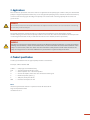
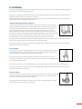
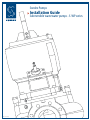
 Sondex Pumps
Installation Guide
Submersible wastewater pumps - S-WP series
Rev.16102013
1. Content
2. Identification plate.......................................................................................................................................................Page
3. Applications....................................................................................................................................................................Page
4. Product specification..................................................................................................................................................Page
5. Handling..........................................................................................................................................................................Page
6. Installation......................................................................................................................................................................Page
7. Electrical installation...................................................................................................................................................Page
8. Operation........................................................................................................................................................................Page
9. Service & maintenance...............................................................................................................................................Page
Service Instructions for S-WP1-70, S-WP1-80, S-WP2-80, S-WP2-100, S-WP2-150...............................Page
Service Instructions for S-WP3-80, S-WP3-100, S-WP3-150..........................................................................Page
Service Instructions for S-WP4-100, S-WP4-150, S-WP4-200, S-WP4-250, S-WP4-300........................Page
10. Technical data 50 Hz...................................................................................................................................................Page
11. Technical data 60 Hz...................................................................................................................................................Page
12. Electrical diagram........................................................................................................................................................ Page
13. EC Declaration of conformity...................................................................................................................................Page
2. Identification plate
Standard nameplate:
Sondex Pumps A/S
Jernet 9 DK-6000 Kolding
Type
No.
Q
H
1/min
P2
PH
A
Hz
V
20m
Class H IP 68
Kg
- THERMALLY PROTECTED
- SEE MANUAL FOR CORD REPLACEMENT
- WARNING - DO NOT OPEN WHEN AN EXPLOSIVE ATMOSPHERE MAY BE PRESENT
2
2
3
3
4
5
6
7
8
8
12
16
20
21
22
23
3. Applications
This installation, operation and service manual is applicable to the pump types S-WP1-4. They are submersible
pumps in degree of protection IP68. They are all designed for pumping water, wastewater with contaminants,
as well as low-viscosity types of sludge. The pumps can also be used as drainage pumps where sand and
gravel occurs.
WARNING
The machines must never be used in flammable or explosive media. If there are local restrictions concerning
fire risks they must be obeyed.
The pumps meet EU’s machine directive, see declaration of conformity at the back of this manual.
Sondex Pumps guarantees that the pumps’ airborne noise level does not exceed 70 dbA at normal operation
in submerged installation. At dry installation the noise level is 74 dbA (at normal operation).
WARNING
If people can get physical contact with the pump or the fluid that is being pumped at e.g. open excavations,
building sites or the like, a fault circuit-breaker (HFI) must be mounted in the electrical installation. If the
pump is used in oceans, lakes etc. there must be a minimum safety distance of 20 meters between the
pump and any persons in the water. NOTE that in pools there are special safety restrictions.
4. Product specification
A code system determines the type of pump model as stated here:
Example: S-WP3-150 VX6-300
S-WP3
150
V
X
6
6
300
=
=
=
=
=
=
=
Pump type and module family
Standard outlet discharge in mm
Vortex impeller or C = Channel impeller
Version of impeller, more than one X indicates other types
Number of poles (rpm) e.g.
960 rpm (1150 rpm. 60 Hz)
Diameter of impeller in mm
Motor
Shorted asynchronous motor in 3-phased version for 50 or 60 Hz
Degree of protection IP68
Insulation class H
3
Motor protection
All stators are equipped with 3 built-in thermal switches connected in series. The thermal switches open at
135°C and close again at 90°C.
The wires for the switches are marked “F0” & “F1” and method of installation can be found in the installation
diagram for the pump.
TO MAINTAIN WARRANTY ON THE PUMP, THE THERMAL SENSORS MUST BE CONNECTED PROPERLY
Moisture indicator
The pump is mounted with a moisture sensor as standard. It detects moisture in the stator compartment as
well as the oil compartment simultaneously.
The sensor is connected with the wire marked “D” coming out of the pump. This conductor shall be connected
to a moisture relay, which is built into the electric board. The relay will cut off or signal (depending on
connection) that the pump has moisture or water penetration. The normal alarm level is 100 kΩ for submersed
and for dry installation, both at a voltage of 24V DC.
TO MAINTAIN WARRANTY ON THE PUMP, THE THERMAL SENSORS MUST BE CONNECTED PROPERLY
Motor cable
All standard pumps are delivered with 10 metre cable of the type H07RN-F. For installation of a longer cable
please contact your local Sondex Pumps dealer, who can advice you about volt drop and dimensions. Also
note that cable type and number of cables can vary depending on voltage, start method and country.
Technical specifications
Please see the technical data supplied with the pump for weight, amount of oil and coolant, rpm, nominal
power etc.
Cooling system
The pumps can optionally be equipped with an internal cooling system for cooling the motor and critical
parts. The cooling system is a closed circuit system, which means the system will not be clogged or lose its
function due to polluted water. Amount of cooling fluid and type is stated in the technical specifications
supplied with the pump.
5. Handling
The pump must be packaged properly during transport to avoid damage to the pump or surroundings. It can
be transported and/or stored in vertical or horizontal position. Check that the cables are packaged securely.
The cable ends are sensitive towards moisture and water, which could seep into the coupling room and the
motor.
Always place the pump on a stable surface, so it cannot tip over during service, transport, testing and
installation. Never lift the pump in the cables, always use its original lifting handles, which are designed
in accordance with the machine’s weight. Furthermore, check before lifting that the screws, which hold
the lifting handles, are securely fastened.
For storage for long periods of time the pump must be serviced and checked again before use. Before electrical
connection the impeller shall be turned by hand to ensure the correct friction of the mechanical seal. Also
check the cable for breaks and assess whether the cable is flexible and smooth enough.
4
6. Installation
The immersion depth for pumps covered by this manual is max 20 meters. The temperature of the pumped
media must not continuously exceed 45°C.
Accidents in relation to installation can be minimised by taking special care. Be especially careful with the
pump’s weight and the risk of electrical accidents.
When lifting with hoisting equipment, these must always be of the correct dimensions with regard to the
lifted weight. Never walk under hanging loads.
Installation with submerged pump on coupling foot
Cables for the pump have to be installed in such a way that they avoid any sharp
bends or getting squeezed. Never let the cables hang In a way that they might get
sucked into the pump. Mount the coupling foot at the bottom of the well with
expanding bolts or glue-anchors of a size as stated on the dimension drawing.
When mounting the upper guide brackets, the guide tubes must be vertical and
parallel. Connect the discharge pipe to the coupling foot’s flange and attach a possible
automatic non-return valve followed by a check valve in the mentioned order.
The hoisting device must be installed directly above the pump’s centre of gravity.
The pump will then automatically connect at bottom position and loosen again when lifted. Now connect the
cables to the electrical board and the pump is ready for operation.
Check that the pipe dimensions are correct according to the required capacity. Contact your local Sondex
Pumps dealer, who can advise you.
Dry pit installation
The pump unit is delivered with support legs. If the legs are adjustable, the height is
regulated by loosening the two bolts on each leg, and tightens them again at the
desired height. Then mount the inlet and discharge pipes.
To make mounting and demounting of the motor part during service easier, we
recommend mounting a valve on the suction side. This will also ease the adjustment
or changing of the wear ring.
The discharge side can also be equipped with a pressure gauge to easily check the pumps performance.
Check that the pipe dimensions are correct according to the required capacity. Contact your local Sondex
Pumps dealer, who can advise you.
Portable installation
When mounting this installation type, it is very important that the cables are installed
in such a way so they do not bend, get damaged by vehicles etc. It is also important
that there is no pulling in the cables or the hose.
The pump must be mounted on a solid surface and in a vertical position so it does
not tip over or “dig” into the sand, sludge etc.
5
The pump can also be mounted lying down, but note that the pump’s inlet is exposed whereby all physical
contact must be avoided. Keep a minimum safety distance of 5 metres from a pump in operation. The
pump is able to give a very powerful suction under water.
Never underestimate this and also mount a plate that can be screwed onto the pump’s frame to avoid
large objects being sucked into the pump.
NOTE that the loss of pressure in a hose is much greater than in a pipe. Contact your local Sondex Pumps
dealer for determining hose loss and dimensions.
7. Electrical installation
The pumps electrical equipment are made according to EN60204-1.
An authorised electrician must perform all electrical connections.
The pump must be mounted with a motor guard and a fault circuit breaker.
The pump should be grounded according to local regulations. The grounding wire are marked with a grounding
symbol
Check that the pump’s identification plate is in accordance with network voltage, frequency, fuse size and
start form.
The network voltage must not fluctuate more than ±5% of the pump voltage marking. If more, the motor’s
life will be reduced and the motor itself could short-circuit.
Motor connection
Connection of the stator wires has to be done according to the connection diagram supplied with the pump.
The proper connection of the motor depends on knowing the number of conductors as well as sensor cables.
The electric board must be equipped with a motor guard that fits the motor size. This relay must be set as follows:
Direct start
The motor guard is set to the current (measured in ampere) that is stated on the identification plate. When
the thermal surveillance is connected, the motor guard’s setting is increased by 10 percent.
Star-delta start
The motor guard is set to the current (measured in ampere) that is stated on the identification plate multiplied
by 0.58. When the thermal overload switches are connected add 8 percent to the calculated value.
The grid must be secured with ordinary safety cutouts.
Thermal protection:
All pumps, are equipped with thermal overload switches built into the stator. These are marked F0 & F1. The
thermal protection conductors must be connected in series with the motor guard in the electric board according
to the connection diagram supplied with the pump. If this protection is not connected the guarantee will be
void in case of damage.
Moisture sensor:
The conductor marked “D” is connected to a moisture sensor, which is placed between the oil housing and
the motor housing. This sensor must be connected to a relay in the electric board. The relay must be connected
6
to the safety circuit and sound the alarm and at the same time stop the pump when moisture is registered in
oil or stator housing. For further information on connection, see the connection diagram supplied with the
pump. Your local Sondex Pumps dealer can supply you with the correct relay as an accessory.
Changing the Cable
Note that a damaged cable always has to be replaced. Connecting the pump with a defective cable can be
life endangering. Never try to lengthen the cable, only use cables in complete length, as water would be able
to get into the motor and damage it.
Check the following to avoid water getting into the pump when changing the cable:
a) Cable packing of rubber as well as cable washers must fit the cable dimension perfectly.
b) The cable’s outer diameter must not be deformed. Always cut off a piece so it will seal in a new place in case of a reused cable.
c) Use grease before connecting.
NOTE that the grounding conductor must be longer in the pump, and in a connector at the opposite end.
If the motor cable is torn accidentally, the ground wire will therefore be the last to be torn.
EMC – Electromagnetic compatibility
The pump does not give out electromagnetic radiation.
The pump does not have elements that generate electromagnetic radiation or that are sensitive to
electromagnetic radiation. The pumps are seen to live up to directive 89/336/EEC – concerning
electromagnetic compatibility with later amendments.
Electromagnetic radiation can occur during frequency control of the pump. Hence, the pump can be ordered
with a shielded cable.
8. Operation
Never start up a pump with incompletely connected cables or non-operational overload switches and
leakage sensor
Before the pump is started, the rotation direction must be checked. At start the motors starting torque will
cause the pump to jerk. The start reaction will be counter clockwise, seen from the top of the motor.
The starting torque can be very powerful even with small pumps. Never hold on to the pump and do not
start the pump when hanging in free air.
Place the pump solid so it cannot rotate or tip over before starting.
Never start the pump without impeller, the pump must be fully assembled and ready for operation.
At wrong start reaction two phases must be switched. See the connection diagram.
NOTE that the pump at dry running or wrong rotation can get very hot and make a loud noise.
Before any inspection, service or repair of the pump, it has to be physically disconnected from the power
supply. Remove connectors or dismount the wires in the electric board. An emergency stop can be
released or be defective and start the pump by mistake. Observe this before the motor part is removed
from the motor housing and before any contact with the impeller.
7
9. Service & maintenance
The pump is disconnected from the power supply before the work is started (as described in “Operation”).
All pumps require regular control and preventive maintenance to operate economically and reliably.
The pump should be checked every 6 months and during possible extreme operating conditions more often.
Your local Sondex Pumps dealer can advise you about preventive maintenance. For complete overhaul of the
pump contact an authorised Sondex Pumps workshop or your local Sondex Pumps dealer.
For service on and around the pump a high hygiene must be practiced. Use gloves. Clean the pump carefully
before dismantling it. Follow local and national safety instructions.
WARNING
Before any inspection and service is carried out, make sure that the electrical power supply is
disconnected from any power source. Use a skilled electrician to disconnect the power.
Service Instructions for S-WP1-70, S-WP1-80, S-WP2-80, S-WP2-100, S-WP2-150
Type W - Wet Pit Installation
lnstalled on a guide rail system with a quick-release discharge connection bracket (DCB). The DCB is bolted
to the floor of the sump. The volute is equipped with an adapter to guide the pump via two 2” guide rails in
order to secure connection on the DCB.
Type D - Dry Pit Installation
lnstalled in a dry well. The pump has a factory mounted adjustable stand. The height of the stand makes it
possible to install a standard suction elbow. The pump volute is drilled for standard DN flange.
Type P - Portable Pit or fixed installation
A version of pump, which is suitable for temporary or permanent installations. The pump is equipped with a
steel stand and either a threaded (BSP) or plain hose connection.
The Volute
The volutes are equipped with adjustable wear rings as standard. The volute has 2 fast lock latches for easy
release between motor unit and volute.
Removal from the wet well
Lift the pump from the sump and clean thoroughly.
Removal of the volute
The motor unit is connected to the volute with two fast lock latches. Loosen the latches and lift the motor
unit out from the volute.
Changing the oil
Remove the inlet and outlet plugs. Tilt the pump against the outlet and discharge used oil according to the
local regulations.
Fasten the outlet plug and fill with new oil and fasten the inlet plug.
Type of oil: Hydraulic DTE 24 or similar.
Qty: S-WP1
0.32 l
Qty: S-WP2
0.45 l
Changing the cooling liquid
Remove the cooling liquid plug on the cooling flange (water out). Remove the plug on top of the cooling
jacket (water inlet) for fast emptying. Re-plug the water outlet. Slowly fill the new cooling liquid into the
water inlet on top of the cooling jacket.
8
Note! Do not forget to tighten the plugs after filling.
Cooling liquid, quantity (l): S-WP1: 3.00 l
S-WP2: 6.00 l
(20% Propylene glycol DOWCAL ® 20: 80% water)
Removal of the impeller
The impeller is fixed to the shaft with a washer and a screw. Secure the impeller and remove the impeller bolt
with a wrench.
Removal of the seal cartridge
Disassemble volute and impeller as above, and empty the motor of cooling liquid and oil. Lay the rotating
element on its side. Remove the four screws that hold the seal cartridge. The cartridge can be removed from
the oil chamber by inserting the set screws into the “jacking holes” in the cartridge, which will force the
cartridge from the lower bearing housing.
Changing the cable seal
After disassembling or if there is water in the stator housing, the cable seal has to be replaced. Measure the
cable diameter with a slide gauge and compare with the holes in the cable gland seal and the spacers so
that the dimensions are alike. Pull the seal onto the cable with one spacer underneath. Pull the cable as far
through the cover so that a new part of the cable gets jammed when tightening the cable gland. Tighten the
four screws of the cable gland.
Removal of the cooling jacket
Drain out cooling water. Disassemble by removing the four screws that fix the jacket and lift it off. The cooling
tubes can be “clicked” out without any tools and can be reinstalled. Remember to inspect the o- rings on the
cooling tubes.
Check the stator unit
lf the motor protection trips repeatedly, the stator must be inspected. Remove the stator housing and disconnect
the wires. (Make sure that the wires are marked so that you are able to reconnect). Check the insulation
resistance with an insulation tester (min. 500 V). Test between U1, V1 and W1 and GND.
Test between U1, V1 and W1. The insulation resistance must exceed 1 mega ohm. lf the insulation resistance
is below 1 mega ohm, clean the stator and dry it in an oven for 2-3 hours at 100 degr. C.
Check the circuit of the three built-in thermal overload switches using a buzzer or other measuring device.
Before reconnecting:
Check that the motor cable has no broken wires. Check the motor cable insulation with a 500V insulation
tester, between the wires.
Make sure you have connectors in order to secure good wire connections.
Removal of the stator housing
Mark the stator housing position on the bearing house to be able to reinstall correctly. Remove the four
screws fixing the stator casing. Lift the stator casing approx. 5 cm from the shaft and rotor - use a hoist.
Disconnect the wire from the moisture sensor. Continue lifting off the stator housing.
Disassembling the rotor and bearings
When the stator housing has been removed the shaft with rotor and bearings have to be lifted out. (Lower
bearing might stay in the lower bearing house). Do not reuse worn bearings or bearings which have been in
contact with water.
9
Assembling
Clean all O-ring grooves and all other contact surfaces carefully. Use a wire brush when necessary. Change all
O-rings. Lubricate all O-rings with oil or grease to prevent the O-rings from getting stuck or damaged when
remounted. Also lubricate the threads on all the screws to facilitate disassembling when servicing next time.
Mounting the bearings
Check that the shaft is straight and that the key way is not damaged. Polish possible scratches and burrs off.
Push the upper bearing into its position. lf pressure is needed, then put pressure only on the inner ring of the
bearing, using a piece of pipe and a soft hammer. Mount the lower bearing by using only your hands. Do not
forget to fill the bearings with grease.
Mounting the rotor in the oil housing
Push the lower bearing into the bearing seat by pushing lightly with your hand at the end of the shaft.
Mounting the seal cartridge
Put down the driving unit. Lubricate the shaft and all four O-rings on the seal unit (three external on the seal
housing and one internal in the seal cap). Carefully push the seal unit onto the shaft, and place into position
by aligning the screw holes. Do not use hard striking tools. Tighten the seal unit by fastening the four screws.
All 4 screws have to follow each other to make sure that the seal unit does not tilt.
NOTE! Never run the motor without having the impeller mounted, if the seal is mounted. This will cause
damage to O-rings in the seal.
Mounting the impeller
Turn the shaft so that the key way is upward. Put the key in its groove and push the impeller onto the shaft.
Lock the impeller from rotating with a pipe or similar and fasten the impeller washer and screw.
Mounting the stator
Erect the oil housing and clean all contact surfaces between the oil housing and the stator unit with a wire
brush. Lubricate and mount a new o-ring on the oil housing. The stator is now ready to be mounted on the oil
housing. Lift the stator unit with a lifting device and lower it carefully over the rotor. Make sure that the rotor
does not damage the windings or the stator stick. Remember to connect the wire from the moisture sensor.
Fasten the stator with its four screws. Make sure that the external markings are in line.
Mounting the cooling jacket
Put the gasket on top of the stator house. Fit the 2 external cooling tubes. Make sure that the o-rings are
changed. Lower the cooling mantle over the stator casing and make sure that the external markings are in
line and that the cooling pipes are in their right positions. Fasten the cooling jacket with four screws.
Mounting the motor unit in the volute
Turn the latch bolts so that the driving unit is free down to the upper edge of the volute. Turn the latch bolts
in and fasten the screws alternately. Make sure that the external markings are in line. Tighten completely by
hand using a 24 mm wrench. Once hand tightened, use a sledge hammer and tighten by another 1/4 to 1/2 turn
to assure a tight connection.
Adjusting the wear ring
Lay the pump down on its side and check the clearance between impeller and wear ring. The clearance
should be max. 0.4 mm. The wear ring is placed on the bottom side of the volute and is fastened by three
screws placed horizontally. Loosen these screws and adjust with the three vertically placed screws. When
necessary, strike carefully with a hammer or plastic club. When the distance is adjusted the horizontally
placed screws can be tightened.
Note! This only applies if using channel impeller. lf using vortex impeller do not adjust the wear ring!
10
Testing
Connect the cables to the electric mains and start the pump. This should only be done by a qualified electrician. Check the direction of rotation - it has to be clockwise, when viewed from the top of the motor. The
starting reaction will be in the opposite direction. Make sure you have a firm grasp on the pump.
Tightening torque screws
Size (Nm)
M6 : 7
M8 :17
M10 : 33
M12 : 57
M14 : 91
M16 :140
Tightening factor
Cable gland: A specific estimation of the tightening factor cannot be given for the cable gland. Tighten it until
the rubber offers good resistance, and thereafter one more full rotation for each screw.
Size (Nm)
Impeller bolt
(M12 Bumax) 115
Latch bolt
(M16) 95
11
Service Instructions for S-WP3-80, S-WP3-100, S-WP3-150
Type W - Wet Pit Installation
lnstalled on a guide rail system with a quick-release discharge connection bracket (DCB). The DCB is bolted
to the floor of the sump. The volute is equipped with an adapter to guide the pump via two 2” guide rails in
order to secure connection on the DCB.
Type D - Dry Pit Installation
lnstalled in a dry well. The pump has a factory mounted adjustable stand. The height of the stand makes it
possible to install a standard suction elbow. The pump volute is drilled for standard DN flange.
Type P - Portable Pit or fixed installation
A version of pump, which is suitable for temporary or permanent installations. The pump is equipped with a
steel stand and either a threaded (BSP) or plain hose connection.
The Volute
The volutes are equipped with adjustable wear rings as standard. The volute on the S-WP3-80 is only available
in the Vortex impeller design and has no wear ring. The volute has 4 fast lock latches for easy release between
motor unit and volute.
Removal from the wet well
Lift the pump from the sump and clean thoroughly.
Removal of the volute
The motor unit is connected to the volute with four latch bolts. Loosen the locking screws and turn the latch
bolts 90°. Lift the motor unit out from the volute.
Changing the oil
Remove the plug marked “oil out” and let the used oil pour out through the groove under the plug. Discard
used oil in accordance with local regulations.
Fasten the plug so that the lower but not the top O-ring gasket seals.
Oil: white oil (Hydraulic oil DTE24, or similar).
Oil amount: 0.15 l.
lnspect the motor housing by removing the screw marked “motor”. Tilt the pump slightly. lf water, oil or other
debris is present in the motor housing, a full dismantling is required.
Changing the cooling liquid
Remove the cooling liquid plug on the cooling flange (water out). Remove the plug on top of the cooling
jacket (water inlet) for fast emptying. Re-plug the water outlet. Slowly fill the new cooling liquid into the
water inlet on top of the cooling jacket.
Note! Do not forget to tighten plugs after filling.
Cooling liquid, quantity (l): 10,50
(20% Propylene glycol DOWCAL ® 20: 80% water)
Removal of the impeller
The impeller is fixed to the shaft with a washer and a screw. Secure the impeller and remove the impeller bolt
with a wrench.
Removal of the seal cartridge
Disassemble volute and impeller as above, and empty the motor of cooling liquid and oil. Lay the rotating
element on its side. Remove the four screws that hold the seal cartridge. The cartridge can be removed from
the oil chamber by inserting the set screws into the “jacking holes” in the cartridge, which will force the
cartridge from the lower bearing housing.
12
Disassembling the connection cover
Remove the four screws fixing the cover. Gently lift the cover to gain access to the terminal board area. Be
careful not to damage the cable and motor connections. lf disconnecting wires make sure that you are able
to reinstall them correctly.
Removal of the cooling jacket
Drain out cooling water. Disassemble by removing the four screws that fix the jacket and lift it off. lt is possible
to lift it off without removing the cable cover. The cooling tubes can be “clicked” out without any tools and
can be reinstalled. Remember to inspect o-rings on cooling tubes.
Check the stator unit
lf the motor protection trips repeatedly, the stator must be inspected. Disassemble the cable cover with the
motor cable. Disconnect the stator wires. Check the insulation resistance with min. 500V insulation tester.
Test between U1, V1 and W1 and GND.
Test between U1, V1 and W1. The insulation resistance must exceed 1 mega ohm. lf the insulation resistance
is below 1 mega ohm, clean the stator and dry it in an oven for 2-3 hours at 100 degr. C.
Check the circuit of the three built-in thermal overload switches using a buzzer or other measuring device.
Before reconnecting:
Check that the motor cable has no broken wires. Check the motor cable insulation with a 500V insulation
tester, between the wires.
Removal of the stator housing
Mark the stator housing position on the bearing house to be able to reinstall correctly. Remove the six screws
fixing the stator casing. Lift the stator casing approx. 5 cm from the shaft and rotor - use a hoist. Disconnect
the wire from the moisture sensor. Continue lifting off the stator housing.
Disassembling the rotor and bearings
When the stator housing has been removed the bearing cover is removed (4 screws). Lift out the shaft with
rotor and bearings. (Lower bearing might stay in the lower bearing house). Do not reuse worn bearings or
bearings which have been in contact with water.
Assembling
Clean all O-ring grooves and all other contact surfaces carefully. Use a wire brush when necessary. Change all
O-rings. Lubricate all O-rings with oil or grease to prevent the O-rings from getting stuck or damaged when
remounted. Also lubricate the threads on all the screws to facilitate disassembling when servicing next time.
Mounting the bearings
Check that the shaft is straight and that the key way is not damaged. Polish possible scratches and burrs off.
Push the upper bearing into its position. lf pressure is needed, then put pressure only on the inner ring of the
bearing, using a piece of pipe and a soft hammer. Place the bearing cover on the shaft and mount the lower
bearing by using only your hands. Do not forget to fill the bearings with grease.
Mounting the rotor in the oil housing
Push the lower bearing into the bearing seat by pushing lightly with your hand at the end of the shaft. Lock
the rotor by fastening the four screws of the bearing house.
Mounting the seal cartridge
Put down the driving unit. Lubricate the shaft and all four O-rings on the seal unit (three external on the seal
housing and one internal in the seal cap). Push the seal unit onto the shaft, and place into position by aligning
the screw holes. Do not use hard striking tools. Tighten the seal unit by fastening the four screws. All 4 screws
have to follow each other to make sure that the seal unit does not tilt.
13
NOTE! Never run the motor without having the impeller mounted, if the seal is mounted. This will
cause damage to O-rings in the seal.
Mounting the impeller
Turn the shaft so that the key way is upward. Put the key in its groove and push the impeller onto the shaft.
Lock the impeller from rotating with a pipe or similar and fasten the impeller washer and screw.
Mounting the cable seal
lf water has penetrated the cable seal and reached the terminal board, the cable seals have to be replaced.
The cable seal should be replaced after every disassembly of the cable gland. Measure the cable diameter
with a slide gauge and compare it to the holes in the cable seal and the spacers, so that the dimensions are
correct. Pull the seal onto the cable with one washer on each side. Pull the cable through the cover so that
the cable with its cover extends through the cable gland and into the terminal area when tightening the
cable lead-in. After tightening, the strain relief clamp is fastened. Turn the clip’s long pin down to prevent the
cable lead-in from unthreading.
Mounting the stator
Erect the oil housing and clean all contact surfaces between the oil housing and the stator unit with a wire
brush. Lubricate and mount a new o-ring on the oil housing. The stator is now ready to be mounted on the oil
housing. Lift the stator unit with a lifting device and lower it carefully over the rotor. Make sure that the rotor
does not damage the windings or the stator stick. Remember to connect the wire from the moisture sensor.
Fasten the stator with its six screws. Make sure that the external markings are in line.
Mounting the coupling cover
Keep the cover near the terminal board to avoid too long cables. Connect the cables according the wiring
diagram in the CE manual following the pump. Remember that the ground cable should be longer than the
other cables for safety reasons. Before the cover is fastened, it should be turned one half turn to avoid having
the cables pinched under the cap.
Mounting the cooling jacket
Fit the internal cooling pipe so that it is in the right position and fix with the 2 external cooling tubes. Make
sure that the o-rings are changed. Lower the cooling mantle over the stator casing and make sure that the
external markings are in line, and that the cooling tubes are in their right positions. Fasten the cooling jacket
with four screws.
Mounting the motor unit to the volute
Turn the latch bolts so that the driving unit is free down to the upper edge of the volute. Turn the latch bolts
in and fasten the screws alternately. Make sure that the external markings are in line. Tighten completely by
hand using a 24 mm wrench. Once hand tightened, use a sledge hammer and tighten by another 1/4 to 1/2turn
to assure a tight connection.
Adjusting the wear ring
Lay the pump down on its side and check the clearance between impeller and wear ring. The clearance
should be max. 0.4 mm. The wear ring is placed on the bottom side of the volute and is fastened by three
screws placed horizontally. Loosen these screws and adjust with the three vertically placed screws. When necessary, strike carefully with a hammer or plastic club. When the distance is adjusted the horizontally placed
screws can be tightened.
Note! This only applies if using channel impeller. lf using vortex impeller do not adjust the wear ring!
Testing
Connect the cables to the electric mains and start the pump. This should only be done by a qualified electrician.
The arrow on the cover indicates the direction of rotation - clockwise, when viewed from the top of the motor.
The starting reaction will be in the opposite direction. Make sure you have a firm grasp on the motor.
14
Tightening torque screws
Size (Nm)
M6 : 7
M8 :17
M10 : 33
M12 : 57
M14 : 91
M16 :140
Tightening factor
Cable gland: A specific estimation of the tightening factor cannot be given for the cable gland. Tighten it
until the rubber offers resistance, and thereafter one more full rotation.
Size (Nm)
Impeller bolt
(M12 Bumax) 115
Latch bolt
(M16) 95
15
Service Instructions for S-WP4-100, S-WP4-150, S-WP4-200, S-WP4-250, S-WP4-300
Type W - Wet Pit Installation
lnstalled on a guide rail system with a quick-release discharge connection bracket (DCB). The DCB is bolted to
the floor of the sump. The volute is equipped with an adapter to guide the pump via two 2” guide rails in order
to secure connection on the DCB. ln the S-WP4-250 and S-WP4-300 version the size of the guide rails is 3”.
Type D - Dry Pit Installation
lnstalled in a dry well. The pump has a factory mounted adjustable stand. The height of the stand makes it
possible to install a standard suction elbow. The pump volute is drilled for standard DN flange.
Type P - Portable Pit or fixed installation
A version of pump, which is suitable for temporary or permanent installations. The pump is equipped with a
steel stand and either a threaded (BSP) or plain hose connection.
The Volute
The volutes are equipped with adjustable wear rings as standard.
Removal from the wet well
Lift the pump from the sump and clean thoroughly.
Removal of the volute
Before disassembly the pump has to be disconnected from the electrical source. The motor unit is connected
to the volute with six latch bolts. Loosen the locking screws and turn the latch bolts 90°. Lift the motor unit
out from the volute.
Changing the oil
Remove the plug marked “oil out” and let the used oil pour out through the groove under the plug. Discard
used oil in accordance with local regulations.
Fasten the plug so that the lower but not the top O-ring gasket seals.
Oil: white oil (Hydraulic oil DTE24, or similar).
Oil amount: 0.4 l.
lf there is any problem filling in oil, tilt the pump slightly so that air can escape.
lnspect the motor housing by removing the screw marked “motor”. Tilt the pump slightly. lf water, oil or other
debris is present in the motor housing, a full dismantling is required.
Changing the cooling liquid
Remove the cooling liquid plug on the cooling flange (water out). Remove the plug on top of the cooling
jacket (water inlet) for fast emptying. Re-plug the water outlet. Slowly fill the new cooling liquid into the
water inlet on top of the cooling jacket.
Note! Do not forget to tighten plugs after filling.
Cooling liquid, quantity (l): 44,0
(20% Propylene glycol DOWCAL ® 20: 80% water)
Removal of the impeller
The impeller is fixed to the shaft with a washer and a screw. Secure the impeller and remove the impeller bolt
with a wrench.
Removal of the seal cartridge
Disassemble volute and impeller as above, and empty the motor of cooling liquid and oil. Lay the rotating
element on its side. Remove the four screws that hold the seal cartridge. The cartridge can be removed from
the oil chamber by inserting the set screws into the “jacking holes” in the cartridge, which will force the cartridge from the lower bearing housing.
16
Disassembling the connection cover
Remove the six screws fixing the cover. Gently lift the cover to gain access to the terminal board area.
Be careful not to damage the cable and motor connections. lf disconnecting wires make sure that you are
able to reinstall them correctly.
Removal of the terminal housing
Disconnect all wires from the terminal board. The terminals are spring operated and can be opened by a
screwdriver. Open the cable glands for wiring to the stator. Remove the 6 screws and lift the terminal housing
carefully. Do not damage the wires to the stator.
Removal of the cooling jacket
Drain out cooling water. Disassemble by lifting off the jacket. lnspect where the o-rings are located.
Check the stator unit
lf the motor protection trips repeatedly, the stator must be inspected. Open the terminal housing cover.
Disconnect the stator wires (spring terminals). Check the insulation resistance with min. 500V insulation
tester. Test between U1, V1 and W1 and GND.
Test between U1, V1 and W1. The insulation resistance must exceed 1 mega ohm. lf the insulation resistance
is below 1 mega ohm, clean the stator and dry it in an oven for 2-3 hours at 100 degr. C.
Check the circuit of the three built-in thermal overload switches using a buzzer or other measuring device.
Before reconnecting:
Check that the motor cable has no broken wires. Check the motor cable insulation with a 500V insulation
tester, between the wires.
Removal of the stator housing
Mark the stator housing position on the bearing house to be able to reinstall correctly. Remove the six screws
fixing the stator casing. Lift the stator casing approx. 5 cm from the shaft and rotor - use a hoist. Disconnect
the wire from the moisture sensor. Continue lifting off the stator housing.
Disassembling the rotor and bearings
When the stator housing has been removed, the shaft with rotor and bearing has to be lifted out. (Lower
bearing will stay in the lower bearing house). Do not reuse worn bearings or bearings which have been in
contact with water.
Assembling
Clean all O-ring grooves and all other contact surfaces carefully. Use a wire brush when necessary. Change all
O-rings. Lubricate all O-rings with oil or grease to prevent the O-rings from getting stuck or damaged when
remounted. Also lubricate the threads on all the screws to facilitate disassembling when servicing next time.
Mounting the bearings
Check that the shaft is straight and that the key way is not damaged. Polish possible scratches and burrs off.
Push the upper bearing into its position. lf pressure is needed, then put pressure only on the inner ring of the
bearing, using a piece of pipe and a soft hammer. Put the shaft through the shaft hole in the bearing house.
Mount the lower bearing from the bottom side of the bearing house. You may need a piece of pipe and a soft
hammer to install the bearings. The lower bearing is a double bearing. Make sure that the bearings are placed
face to face.
17
Do not forget to fill the bearings with grease.
Mounting the seal cartridge
Put down the motor unit. Lubricate the shaft and all four O-rings on the seal unit (three external on the seal
housing and one internal in the seal cap). Carefully push the seal unit onto the shaft, and place into position
by aligning the screw holes. Do not use hard striking tools. Tighten the seal unit by fastening the four screws.
All 4 screws have to follow each other to make sure that the seal unit does not tilt.
NOTE! Never run the motor without having the impeller mounted, if the seal is mounted. This will
cause damage to the O-rings in the seal.
Mounting the impeller
Turn the shaft so that the key way is upward. Put the key in its groove and push the impeller onto the shaft.
Lock the impeller from rotating with a pipe or similar and fasten the impeller washer and screw.
Mounting the cable seal
lf water has penetrated the cable seal and reached the terminal board, the cable seals have to be replaced.
The cable seal should be replaced after every disassembly of the cable gland. Measure the cable diameter
with a slide gauge and compare it to the holes in the cable seal and the spacers, so that the dimensions are
correct. Pull the seal onto the cable with one washer on each side. Pull the cable through the cable gland so
that the cable with its cover extends through the cable gland and into the terminal area when tightening the
cable lead-in. After tightening, the strain relief clamp is fastened. Turn the clip’s long pin down to prevent the
cable lead-in from unthreading.
Mounting the stator
Erect the oil housing and clean all contact surfaces between the oil housing and the stator unit with a wire
brush. Lubricate and mount a new o-ring on the oil housing. The stator is now ready to be mounted on the oil
housing. Lift the stator unit with a lifting device and lower it carefully over the rotor. Make sure that the rotor
does not damage the windings or the stator stick. Remember to connect the wire from the moisture sensor.
Fasten the stator with its six screws.
Make sure that the external markings are in line.
Mounting the cooling jacket
Make sure that the o-rings are changed. Lower the cooling mantle over the stator casing and make sure that
the external markings are in line.
Mounting the terminal housing
Make sure that all cables go though the holes in the cable gland. Be careful not to damage the wires from the
stator. Tighten the 6 screws fixing the terminal housing and cooling jacket. Reconnect the wires and cables
according to the marking made before dismantling. Close the terminal housing with the cover and make sure
that the o-ring is changed.
18
Mounting the motor unit to the volute
Turn the latch bolts so that the driving unit is free down to the upper edge of the volute. Turn the latch bolts
in and fasten the screws alternately. Make sure that the external markings are in line. Tighten completely by
hand using a 24 mm wrench. Once hand tightened, use a sledge hammer and tighten by another 1/4 to 1/2 turn
to assure a tight connection.
Adjusting the wear ring
Lay the pump down on its side and check the clearance between impeller and wear ring. The clearance
should be max. 0.4 mm. The wear ring is placed on the bottom side of the volute and is fastened by six screws
placed horizontally. Loosen these screws and adjust the wear ring. When necessary, strike carefully with a
hammer or plastic club. When the distance is adjusted the horizontally placed screws can be tightened.
Note! This only applies if using channel impeller. lf using vortex impeller do not adjust the wear ring!
Testing
Connect the cables to the electric mains and start the pump. This should only be done by a qualified electrician.
The arrow on the cover indicates the direction of rotation - clockwise, when viewed from the top of the motor.
The starting reaction will be in the opposite direction. Make sure you have a firm grasp on the motor.
Tightening torque screws
Size (Nm)
M6 : 7
MB :17 M10 : 33 M12 : 57 M14 : 91 M16 :140 htening factor
Cable gland: A specific estimation of the tightening factor cannot be given for the cable gland.
Tighten it
until the rubber offers resistance, and thereafter one more full rotation.
Size (Nm)
mpeller bolt (M12 Bumax) 115 Latch bolt
(M16) 95
19
10. Technical data - 50Hz
Type
20
P2 [kW]
Rpm IA /IN
S-WP0-30-2 - 1.ph 0,35
2850 3,9
S-WP0-37-2
0,55
2850 3,5
S-WP0-50-2 - 1.ph
0,8
2850 4,2
S-WP0-50-2
0,8
2850 4,2
S-WP0-65-2
1,85
2850 3,8
S-WP0-65-2
2,2
2850 4,1
S-WP0-65-4
1,1
1430 4,5
S-WP1-70-2
3,5
2890 6,8
S-WP1-80-4
2,5
1420 5,6
S-WP2-80-2
6,5
2900 8,6
S-WP2-80-2
9
2900 8,6
S-WP2-100-4
4
1440 6,0
S-WP2-100-4
6
1440 6,0
S-WP2-100-4
7
1440 6,8
S-WP2-100-6
2,5
940 4,6
S-WP2-150-4
4
1440 6,0
S-WP2-150-4
6
1440 6,0
S-WP2-150-4
7
1440 6,8
S-WP2-150-6
2,5
940 4,6
S-WP3-80-2
8
2930 6,9
S-WP3-80-2
12,5
2940 6,5
S-WP3-80-2
21
2940 7,0
S-WP3-100-4
7,5
1455 6,7
S-WP3-100-4
9
1455 6,7
S-WP3-100-4
12,5
1460 6,2
S-WP3-100-4
17
1460 6,5
S-WP3-100-4
22
1455 8,3
S-WP3-150-4
7,5
1455 6,7
S-WP3-150-4
9
1455 6,7
S-WP3-150-4
12,5
1460 6,2
S-WP3-150-4
17
1460 6,5
S-WP3-150-4
22
1455 8,3
S-WP3-150-6
6,6
950 5,0
S-WP3-150-6
13,5
960 4,8
S-WP4-100-4
18,5
1465 6,7
S-WP4-100-4
22
1465 6,9
S-WP4-100-4
30
1465 6,3
S-WP4-100-4
37
1465 6,5
S-WP4-100-4
45
1465 6,5
S-WP4-100-4
55
1465 7,8
S-WP4-100-4
65
1475 6,5
S-WP4-150-4
18,5
1465 6,7
S-WP4-150-4
22
1465 6,9
S-WP4-150-4
30
1465 6,3
S-WP4-150-4
37
1465 6,5
S-WP4-150-4
45
1465 6,5
S-WP4-150-4
55
1465 7,8
S-WP4-150-4
65
1475 6,5
S-WP4-150-6
18,5
970 4,9
S-WP4-150-6
22
975 5,6
S-WP4-150-6
30
975 5,7
S-WP4-150-6
37
975 5,8
S-WP4-150-6
45
975 5,8
S-WP4-200-4
18,5
1465 6,7
S-WP4-200-4
22
1465 6,9
S-WP4-200-4
30
1465 6,3
S-WP4-200-4
37
1465 6,5
S-WP4-200-4
45
1465 6,5
S-WP4-200-4
55
1465 7,8
S-WP4-200-4
65
1475 6,5
S-WP4-200-6
18,5
970 4,9
S-WP4-200-6
22
975 5,6
S-WP4-200-6
30
975 5,7
S-WP4-200-6
37
975 5,8
S-WP4-200-6
45
975 5,8
S-WP4-250-4
18,5
1465 6,7
S-WP4-250-4
22
1465 6,9
S-WP4-250-4
30
1465 6,3
S-WP4-250-4
37
1465 6,5
S-WP4-250-4
45
1465 6,5
S-WP4-250-4
55
1465 7,8
S-WP4-250-4
65
1475 6,5
S-WP4-250-6
18,5
970 4,9
S-WP4-250-6
22
975 5,6
S-WP4-250-6
30
975 5,7
S-WP4-250-6
37
975 5,8
S-WP4-250-6
45
975 5,8
S-WP4-300-6
18,5
970 4,9
S-WP4-300-6
22
975 5,6
S-WP4-300-6
30
975 5,7
S-WP4-300-6
37
975 5,8
S-WP4-300-6
45
975 5,8
S-WP4-300-8
15
725 4,9
S-WP4-300-8
18,5
725 4,9
*Coolant = 80% water & 20% propylene glycol
Cable DOL
Cable S/D
3 x 230 V
3 x 400 V
3 x 230 V
3 x 400 V
3x1,5
3x1,5
3x1,5
3x1,5
4x1,5 / 7x1,5
4x1,5 / 7x1,5
4x1,5 / 7x1,5
7x1,5
7x1,5
7x2,5
7x4 & 3x1,5
7x1,5
7x2,5
7x4 & 3x1,5
7x1,5
7x1,5
7x2,5
7x4 & 3x1,5
7x1,5
4x1,5 + 4x4
4x1,5 + 4x10
4x1,5 + 4x16
4x1,5 + 4x4
4x1,5 + 4x6
4x1,5 + 4x10
4x1,5 + 4x16
4x1,5 + 2(4x10)
4x1,5 + 4x4
4x1,5 + 4x6
4x1,5 + 4x10
4x1,5 + 4x16
4x1,5 + 2(4x10)
4x1,5 + 4x4
4x1,5 + 4x10
4x1,5 + 4x16
4x1,5 + 4x25
4x1,5 + 4x35
4x1,5 + 2(4x25)
4x1,5 + 2(4x25)
4x1,5 + 2(4x35)
NA
4x1,5 + 4x16
4x1,5 + 4x25
4x1,5 + 4x35
4x1,5 + 2(4x25)
4x1,5 + 2(4x25)
4x1,5 + 2(4x35)
NA
4x1,5 + 4x16
4x1,5 + 4x25
4x1,5 + 4x35
4x1,5 + 2(4x25)
4x1,5 + 2(4x25)
4x1,5 + 4x16
4x1,5 + 4x25
4x1,5 + 4x35
4x1,5 + 2(4x25)
4x1,5 + 2(4x25)
4x1,5 + 2(4x35)
NA
4x1,5 + 4x16
4x1,5 + 4x25
4x1,5 + 4x35
4x1,5 + 2(4x25)
4x1,5 + 2(4x25)
4x1,5 + 4x16
4x1,5 + 4x25
4x1,5 + 4x35
4x1,5 + 2(4x25)
4x1,5 + 2(4x25)
4x1,5 + 2(4x35)
NA
4x1,5 + 4x16
4x1,5 + 4x25
4x1,5 + 4x35
4x1,5 + 2(4x25)
4x1,5 + 2(4x25)
4x1,5 + 4x16
4x1,5 + 4x25
4x1,5 + 4x35
4x1,5 + 2(4x25)
4x1,5 + 2(4x25)
4x1,5 + 4x16
4x1,5 + 4x16
NA
4x1,5
NA
4x1,5
4x1,5 / 7x1,5
4x1,5 / 7x1,5
4x1,5 / 7x1,5
7x1,5
7x1,5
7x1,5
7x2,5
7x1,5
7x1,5
7x1,5
7x1,5
7x1,5
7x1,5
7x1,5
7x1,5
7x1,5
7x2,5
4x1,5 + 4x6
7x1,5
7x2,5
4x1,5 + 4x4
4x1,5 + 4x6
4x1,5 + 4x10
7x1,5
7x2,5
4x1,5 + 4x4
4x1,5 + 4x6
4x1,5 + 4x10
7x1,5
4x1,5 + 4x4
4x1,5 + 4x6
4x1,5 + 4x10
4x1,5 + 4x16
4x1,5 + 4x16
4x1,5 + 4x25
4x1,5 + 4x35
4x1,5 + 2(4x25)
4x1,5 + 4x6
4x1,5 + 4x10
4x1,5 + 4x16
4x1,5 + 4x16
4x1,5 + 4x25
4x1,5 + 4x35
4x1,5 + 2(4x25)
4x1,5 + 4x6
4x1,5 + 4x10
4x1,5 + 4x16
4x1,5 + 4x25
4x1,5 + 4x25
4x1,5 + 4x6
4x1,5 + 4x10
4x1,5 + 4x16
4x1,5 + 4x16
4x1,5 + 4x25
4x1,5 + 4x35
4x1,5 + 2(4x25)
4x1,5 + 4x6
4x1,5 + 4x10
4x1,5 + 4x16
4x1,5 + 4x25
4x1,5 + 4x25
4x1,5 + 4x6
4x1,5 + 4x10
4x1,5 + 4x16
4x1,5 + 4x16
4x1,5 + 4x25
4x1,5 + 4x35
4x1,5 + 2(4x25)
4x1,5 + 4x6
4x1,5 + 4x10
4x1,5 + 4x16
4x1,5 + 4x25
4x1,5 + 4x25
4x1,5 + 4x6
4x1,5 + 4x10
4x1,5 + 4x16
4x1,5 + 4x25
4x1,5 + 4x25
4x1,5 + 4x6
4x1,5 + 4x10
NA
NA
NA
NA
NA
NA
NA
12x1,5
12x1,5
12x1,5
7x4 & 3x1,5
12x1,5
12x1,5
7x4 & 3x1,5
12x1,5
12x1,5
12x1,5
7x4 & 3x1,5
12x1,5
4x1,5 + 7x2,5
4x1,5 + 2(4x4)
4x1,5 + 2(4x10)
4x1,5 + 7x2,5
4x1,5 + 7x2,5
4x1,5 + 2(4x4)
4x1,5 + 2(4x6)
4x1,5 + 2(4x10)
4x1,5 + 7x2,5
4x1,5 + 7x2,5
4x1,5 + 2(4x4)
4x1,5 + 2(4x6)
4x1,5 + 2(4x10)
4x1,5 + 7x2,5
4x1,5 + 2(4x6)
4x1,5 + 2(4x6)
4x1,5 + 2(4x10)
4x1,5 + 2(4x16)
4x1,5 + 2(4x25)
4x1,5 + 2(4x25)
4x1,5 + 2(4x35)
NA
4x1,5 + 2(4x6)
4x1,5 + 2(4x10)
4x1,5 + 2(4x16)
4x1,5 + 2(4x25)
4x1,5 + 2(4x25)
4x1,5 + 2(4x35)
NA
4x1,5 + 2(4x10)
4x1,5 + 2(4x10)
4x1,5 + 2(4x16)
4x1,5 + 2(4x25)
4x1,5 + 2(4x25)
4x1,5 + 2(4x6)
4x1,5 + 2(4x10)
4x1,5 + 2(4x16)
4x1,5 + 2(4x25)
4x1,5 + 2(4x25)
4x1,5 + 2(4x35)
NA
4x1,5 + 2(4x10)
4x1,5 + 2(4x10)
4x1,5 + 2(4x16)
4x1,5 + 2(4x25)
4x1,5 + 2(4x25)
4x1,5 + 2(4x6)
4x1,5 + 2(4x10)
4x1,5 + 2(4x16)
4x1,5 + 2(4x25)
4x1,5 + 2(4x25)
4x1,5 + 2(4x35)
NA
4x1,5 + 2(4x10)
4x1,5 + 2(4x10)
4x1,5 + 2(4x16)
4x1,5 + 2(4x25)
4x1,5 + 2(4x25)
4x1,5 + 2(4x10)
4x1,5 + 2(4x10)
4x1,5 + 2(4x16)
4x1,5 + 2(4x25)
4x1,5 + 2(4x25)
4x1,5 + 2(4x6)
4x1,5 + 2(4x10)
NA
NA
NA
NA
NA
NA
NA
12x1,5
12x1,5
12x1,5
12x1,5
12x1,5
12x1,5
12x1,5
12x1,5
12x1,5
12x1,5
12x1,5
12x1,5
12x1,5
12x1,5
4x1,5 + 2(4x4)
12x1,5
12x1,5
12x1,5
4x1,5 + 2(4x4)
4x1,5 + 2(4x4)
12x1,5
12x1,5
12x1,5
4x1,5 + 2(4x4)
4x1,5 + 2(4x4)
12x1,5
4x1,5 + 7x2,5
4x1,5 + 2(4x4)
4x1,5 + 2(4x4)
4x1,5 + 2(4x6)
4x1,5 + 2(4x10)
4x1,5 + 2(4x10)
4x1,5 + 2(4x16)
4x1,5 + 2(4x25)
4x1,5 + 2(4x4)
4x1,5 + 2(4x4)
4x1,5 + 2(4x6)
4x1,5 + 2(4x10)
4x1,5 + 2(4x10)
4x1,5 + 2(4x16)
4x1,5 + 2(4x25)
4x1,5 + 2(4x4)
4x1,5 + 2(4x4)
4x1,5 + 2(4x6)
4x1,5 + 2(4x10)
4x1,5 + 2(4x16)
4x1,5 + 2(4x4)
4x1,5 + 2(4x4)
4x1,5 + 2(4x6)
4x1,5 + 2(4x10)
4x1,5 + 2(4x10)
4x1,5 + 2(4x16)
4x1,5 + 2(4x25)
4x1,5 + 2(4x4)
4x1,5 + 2(4x4)
4x1,5 + 2(4x6)
4x1,5 + 2(4x10)
4x1,5 + 2(4x16)
4x1,5 + 2(4x4)
4x1,5 + 2(4x4)
4x1,5 + 2(4x6)
4x1,5 + 2(4x10)
4x1,5 + 2(4x10)
4x1,5 + 2(4x16)
4x1,5 + 2(4x25)
4x1,5 + 2(4x4)
4x1,5 + 2(4x4)
4x1,5 + 2(4x6)
4x1,5 + 2(4x10)
4x1,5 + 2(4x16)
4x1,5 + 2(4x4)
4x1,5 + 2(4x4)
4x1,5 + 2(4x6)
4x1,5 + 2(4x10)
4x1,5 + 2(4x16)
4x1,5 + 7x2,5
4x1,5 + 2(4x4)
Oil [L]
NA
0,6
0,3
0,3
0,4
0,4
0,4
0,32
0,32
0,45
0,45
0,45
0,45
0,45
0,45
0,45
0,45
0,45
0,45
0,15
0,15
0,15
0,15
0,15
0,15
0,15
0,15
0,15
0,15
0,15
0,15
0,15
0,15
0,15
0,4
0,4
0,4
0,4
0,4
0,4
0,4
0,4
0,4
0,4
0,4
0,4
0,4
0,4
0,4
0,4
0,4
0,4
0,4
0,4
0,4
0,4
0,4
0,4
0,4
0,4
0,4
0,4
0,4
0,4
0,4
0,4
0,4
0,4
0,4
0,4
0,4
0,4
0,4
0,4
0,4
0,4
0,4
0,4
0,4
0,4
0,4
0,4
0,4
0,4
Coolant* [L]
(No cooling
jacket)
NA
NA
NA
NA
NA
NA
NA
2,9(0,5)
2,9(0,5)
5,7(1,3)
5,7(1,3)
5,7(1,3)
5,7(1,3)
5,7(1,3)
5,7(1,3)
5,7(1,3)
5,7(1,3)
5,7(1,3)
5,7(1,3)
11(3,5)
11(3,5)
11(3,5)
11(3,5)
11(3,5)
11(3,5)
11(3,5)
11(3,5)
11(3,5)
11(3,5)
11(3,5)
11(3,5)
11(3,5)
11(3,5)
11(3,5)
44(5,5)
44(5,5)
44(5,5)
44(5,5)
44(5,5)
44(5,5)
44(5,5)
44(5,5)
44(5,5)
44(5,5)
44(5,5)
44(5,5)
44(5,5)
44(5,5)
44(5,5)
44(5,5)
44(5,5)
44(5,5)
44(5,5)
44(5,5)
44(5,5)
44(5,5)
44(5,5)
44(5,5)
44(5,5)
44(5,5)
44(5,5)
44(5,5)
44(5,5)
44(5,5)
44(5,5)
44(5,5)
44(5,5)
44(5,5)
44(5,5)
44(5,5)
44(5,5)
44(5,5)
44(5,5)
44(5,5)
44(5,5)
44(5,5)
44(5,5)
44(5,5)
44(5,5)
44(5,5)
44(5,5)
44(5,5)
44(5,5)
44(5,5)
Wet
Install
NA
14
22
22
33
40
32
95
92
148
151
143
151
151
142
148
159
159
156
205
219
252
201
204
225
241
246
215
217
238
255
259
223
270
443
453
499
549
592
604
604
466
476
502
553
596
608
608
486
496
522
573
616
515
525
533
583
626
638
638
533
566
616
625
645
533
513
533
583
626
974
974
533
566
616
625
645
700
733
783
792
1200
710
710
Weight [kg]
Dry
Portable
Install
Install
NA
6
NA
14
NA
22
NA
22
NA
34
NA
41
NA
33
102
104
100
102
150
150
153
154
145
145
153
153
153
153
144
144
150
150
161
161
161
161
158
158
207
207
221
221
254
254
203
207
206
211
227
232
243
247
247
250
217
227
219
229
240
250
257
267
262
270
225
235
272
282
593
474
603
484
626
510
674
560
717
603
729
615
729
615
573
475
583
485
609
510
654
560
697
603
709
615
709
615
593
495
603
505
629
530
674
580
717
623
615
547
625
557
638
570
683
620
726
663
738
675
738
675
638
570
666
603
716
653
725
662
745
682
638
570
618
550
638
570
683
620
726
663
978
974
978
974
638
570
666
603
716
653
725
662
745
682
763
784
791
817
841
867
850
876
1210
1200
774
794
774
794
Base
elbow
NA
5
5
5
13
13
13
35
35
35
35
36
36
36
36
65
65
65
65
36
36
36
36
36
36
36
36
65
65
65
65
65
65
65
36
36
36
36
36
36
36
65
65
65
65
65
65
65
65
65
65
65
65
76
76
76
76
76
76
76
76
76
76
76
235
235
235
235
235
235
235
235
235
235
235
235
235
235
235
235
235
235
235
235
Throughlet Outlet
[mm]
flange
5
36
45
45
55
55
55
60
70
70
70
100
100
100
100
100
100
100
100
70
70
70
100
100
100
100
100
100
100
100
100
100
100
100
80
80
80
80
80
80
80
100
100
100
100
100
100
100
100
100
100
100
100
100
100
100
100
100
100
100
100
100
100
100
100
100
100
100
100
100
100
100
100
100
100
100
100
100
100
100
100
100
100
100
R1”
R1½”
R2”
R2”
R2½”
R2½”
R2½”
DN80
DN100
DN80
DN80
DN100
DN100
DN100
DN100
DN150
DN150
DN150
DN150
DN100
DN100
DN100
DN100
DN100
DN100
DN100
DN100
DN150
DN150
DN150
DN150
DN150
DN150
DN150
DN100
DN100
DN100
DN100
DN100
DN100
DN100
DN150
DN150
DN150
DN150
DN150
DN150
DN150
DN150
DN150
DN150
DN150
DN150
DN200
DN200
DN200
DN200
DN200
DN200
DN200
DN200
DN200
DN200
DN200
DN200
DN250
DN250
DN250
DN250
DN250
DN250
DN250
DN250
DN250
DN250
DN250
DN250
DN300
DN300
DN300
DN300
DN300
DN300
DN300
11. Technical data - 60Hz
Type
P2 [kW]
Rpm IA /IN
S-WP0-30-2 - 1.ph
0,35
3420 3,9
S-WP0-37-2
0,55
3420 3,5
S-WP0-50-2 - 1.ph
0,8
3420 4,2
S-WP0-50-2
0,8
3420 4,2
S-WP0-65-2
1,85
3420 3,8
S-WP0-65-2
2,2
3420 4,1
S-WP0-65-4
1,1
1720 4,5
S-WP1-70-2
4,4
3490 6,8
S-WP1-80-4
3,5
1720 5,6
S-WP2-80-2
7,5
3499 8,6
S-WP2-80-2
11
3499 8,6
S-WP2-100-4
5,6
1740 6,0
S-WP2-100-4
7,3
1740 6,0
S-WP2-100-4
8
1740 6,8
S-WP2-100-6
3,3
1140 4,6
S-WP2-150-4
5,6
1740 6,0
S-WP2-150-4
7,3
1740 6,0
S-WP2-150-4
8
1740 6,8
S-WP2-150-6
3,3
1140 4,6
S-WP3-80-2
9
3530 6,9
S-WP3-80-2
14
3540 6,5
S-WP3-80-2
25
3540 7,0
S-WP3-100-4
11,2
1759 6,2
S-WP3-100-4
14,7
1759 6,2
S-WP3-100-4
20,1
1759 6,5
S-WP3-100-4
26
1755 8,3
S-WP3-150-4
11,2
1759 6,2
S-WP3-150-4
14,7
1759 6,2
S-WP3-150-4
20,1
1759 6,5
S-WP3-150-4
26
1755 8,3
S-WP3-150-6
7,5
1150 5,0
S-WP3-150-6
15
1159 4,8
S-WP4-100-4
26
1765 6,9
S-WP4-100-4
35
1765 6,5
S-WP4-100-4
44
1765 6,5
S-WP4-100-4
53
1765 6,5
S-WP4-100-4
64
1765 7,8
S-WP4-100-4
78
1775 6,5
S-WP4-150-4
26
1765 6,9
S-WP4-150-4
35
1765 6,5
S-WP4-150-4
44
1765 6,5
S-WP4-150-4
53
1765 6,5
S-WP4-150-4
64
1765 7,8
S-WP4-150-4
78
1775 6,5
S-WP4-150-6
22
1170 4,9
S-WP4-150-6
26
1175 5,7
S-WP4-150-6
35
1175 5,6
S-WP4-150-6
44
1175 5,6
S-WP4-150-6
54
1175 5,6
S-WP4-200-4
26
1765 6,9
S-WP4-200-4
35
1765 6,5
S-WP4-200-4
44
1765 6,5
S-WP4-200-4
53
1765 6,5
S-WP4-200-4
64
1765 7,8
S-WP4-200-4
78
1775 6,5
S-WP4-200-6
22
1170 4,9
S-WP4-200-6
26
1175 5,7
S-WP4-200-6
35
1175 5,6
S-WP4-200-6
44
1175 5,6
S-WP4-200-6
54
1175 5,6
S-WP4-250-4
26
1765 6,9
S-WP4-250-4
35
1765 6,5
S-WP4-250-4
44
1765 6,5
S-WP4-250-4
53
1765 6,5
S-WP4-250-4
64
1765 7,8
S-WP4-250-4
78
1775 6,5
S-WP4-250-6
22
1170 4,9
S-WP4-250-6
26
1175 5,7
S-WP4-250-6
35
1175 5,6
S-WP4-250-6
44
1175 5,6
S-WP4-250-6
54
1175 5,6
S-WP4-300-6
22
1170 4,9
S-WP4-300-6
26
1175 5,7
S-WP4-300-6
35
1175 5,6
S-WP4-300-6
44
1175 5,6
S-WP4-300-6
54
1175 5,6
S-WP4-300-8
17
875 4,9
S-WP4-300-8
22
875 4,9
*Coolant = 80% water & 20% propylene glycol
Cable DOL
Cable S/D
3 x 230 V
3 x 400 V
3 x 230 V
3 x 400 V
3x1,5
3x1,5
3x1,5
3x1,5
4x1,5 / 7x1,5
4x1,5 / 7x1,5
4x1,5 / 7x1,5
NA
NA
NA
NA
NA
NA
NA
NA
NA
NA
NA
NA
AWG 4x16 + 4x8
AWG 4x16 + 2(4x8)
NA
AWG 4x16 + 4x6
AWG 4x16 + 2(4x6)
AWG 4x16 + 2(4x6)
NA
AWG 4x16 + 4x6
AWG 4x16 + 2(4x6)
AWG 4x16 + 2(4x6)
NA
AWG 4x16 + 4x6
AWG 4x16 + 2(4x6)
AWG 4x16 + 2(4x2)
AWG 4x16 + 2(4x2)
NA
NA
NA
NA
AWG 4x16 + 2(4x2)
AWG 4x16 + 2(4x2)
NA
NA
NA
NA
AWG 4x16 + 2(4x4)
AWG 4x16 + 2(4x2)
AWG 4x16 + 2(4x2)
NA
NA
AWG 4x16 + 2(4x2)
AWG 4x16 + 2(4x2)
NA
NA
NA
NA
AWG 4x16 + 2(4x4)
AWG 4x16 + 2(4x2)
AWG 4x16 + 2(4x2)
NA
NA
AWG 4x16 + 2(4x2)
AWG 4x16 + 2(4x2)
NA
NA
NA
NA
AWG 4x16 + 2(4x4)
AWG 4x16 + 2(4x2)
AWG 4x16 + 2(4x2)
NA
NA
AWG 4x16 + 2(4x4)
AWG 4x16 + 2(4x2)
AWG 4x16 + 2(4x2)
NA
NA
AWG 4x16 + 4x2
AWG 4x16 + 2(4x4)
NA
4x1,5
NA
4x1,5
4x1,5 / 7x1,5
4x1,5 / 7x1,5
4x1,5 / 7x1,5
AWG 7x14
AWG 7x14
AWG 7x14
NA
AWG 7x14
AWG 7x14
NA
AWG 7x14
AWG 7x14
AWG 7x14
NA
AWG 7x14
AWG 4x16 + 4x12
AWG 4x16 + 4x8
AWG 4x16 + 4x6
AWG 4x16 + 4x10
AWG 4x16 + 4x8
AWG 4x16 + 4x6
AWG 4x16 + 2(4x8)
AWG 4x16 + 4x10
AWG 4x16 + 4x8
AWG 4x16 + 4x6
AWG 4x16 + 2(4x8)
AWG 4x16 + 4x12
AWG 4x16 + 4x8
AWG 4x16 + 4x4
AWG 4x16 + 4x2
AWG 4x16 + 2(4x4)
AWG 4x16 + 2(4x2)
AWG 4x16 + 2(4x2)
AWG 4x16 + 2(4x2)
AWG 4x16 + 4x4
AWG 4x16 + 4x2
AWG 4x16 + 2(4x4)
AWG 4x16 + 2(4x2)
AWG 4x16 + 2(4x2)
AWG 4x16 + 2(4x2)
AWG 4x16 + 4x6
AWG 4x16 + 4x4
AWG 4x16 + 4x2
AWG 4x16 + 2(4x4)
AWG 4x16 + 2(4x2)
AWG 4x16 + 4x4
AWG 4x16 + 4x2
AWG 4x16 + 2(4x4)
AWG 4x16 + 2(4x2)
AWG 4x16 + 2(4x2)
AWG 4x16 + 2(4x2)
AWG 4x16 + 4x6
AWG 4x16 + 4x4
AWG 4x16 + 4x2
AWG 4x16 + 2(4x4)
AWG 4x16 + 2(4x2)
AWG 4x16 + 4x4
AWG 4x16 + 4x2
AWG 4x16 + 2(4x4)
AWG 4x16 + 2(4x2)
AWG 4x16 + 2(4x2)
AWG 4x16 + 2(4x2)
AWG 4x16 + 4x6
AWG 4x16 + 4x4
AWG 4x16 + 4x2
AWG 4x16 + 2(4x4)
AWG 4x16 + 2(4x2)
AWG 4x16 + 4x6
AWG 4x16 + 4x4
AWG 4x16 + 4x2
AWG 4x16 + 2(4x4)
AWG 4x16 + 2(4x2)
AWG 4x16 + 4x6
AWG 4x16 + 4x6
NA
NA
NA
NA
NA
NA
NA
NA
NA
NA
NA
NA
NA
NA
NA
NA
NA
NA
NA
AWG 4x16 + 2(4x12)
AWG 4x16 + 2(4x8)
NA
AWG 4x16 + 2(4x8)
AWG 4x16 + 2(4x6)
AWG 4x16 + 2(4x6)
NA
AWG 4x16 + 2(4x8)
AWG 4x16 + 2(4x6)
AWG 4x16 + 2(4x6)
NA
AWG 4x16 + 2(4x12)
AWG 4x16 + 2(4x6)
AWG 4x16 + 2(4x2)
AWG 4x16 + 2(4x2)
NA
NA
NA
NA
AWG 4x16 + 2(4x2)
AWG 4x16 + 2(4x2)
NA
NA
NA
NA
AWG 4x16 + 2(4x4)
AWG 4x16 + 2(4x2)
AWG 4x16 + 2(4x2)
NA
NA
AWG 4x16 + 2(4x2)
AWG 4x16 + 2(4x2)
NA
NA
NA
NA
AWG 4x16 + 2(4x4)
AWG 4x16 + 2(4x2)
AWG 4x16 + 2(4x2)
NA
NA
AWG 4x16 + 2(4x2)
AWG 4x16 + 2(4x2)
NA
NA
NA
NA
AWG 4x16 + 2(4x4)
AWG 4x16 + 2(4x2)
AWG 4x16 + 2(4x2)
NA
NA
AWG 4x16 + 2(4x4)
AWG 4x16 + 2(4x2)
AWG 4x16 + 2(4x2)
NA
NA
AWG 4x16 + 2(4x6)
AWG 4x16 + 2(4x4)
NA
NA
NA
NA
NA
NA
NA
AWG 12x14
AWG 12x14
NA
NA
AWG 12x14
NA
NA
AWG 12x14
AWG 12x14
NA
NA
AWG 12x14
AWG 4x16 + 2(4x12)
AWG 4x16 + 2(4x12)
AWG 4x16 + 2(4x8)
AWG 4x16 + 2(4x12)
AWG 4x16 + 2(4x12)
AWG 4x16 + 2(4x10)
AWG 4x16 + 2(4x8)
AWG 4x16 + 2(4x12)
AWG 4x16 + 2(4x12)
AWG 4x16 + 2(4x10)
AWG 4x16 + 2(4x8)
AWG 4x16 + 2(4x12)
AWG 4x16 + 2(4x12)
AWG 4x16 + 2(4x8)
AWG 4x16 + 2(4x6)
AWG 4x16 + 2(4x4)
AWG 4x16 + 2(4x2)
AWG 4x16 + 2(4x2)
AWG 4x16 + 2(4x2)
AWG 4x16 + 2(4x8)
AWG 4x16 + 2(4x6)
AWG 4x16 + 2(4x4)
AWG 4x16 + 2(4x2)
AWG 4x16 + 2(4x2)
AWG 4x16 + 2(4x2)
AWG 4x16 + 2(4x8)
AWG 4x16 + 2(4x8)
AWG 4x16 + 2(4x6)
AWG 4x16 + 2(4x4)
AWG 4x16 + 2(4x2)
AWG 4x16 + 2(4x8)
AWG 4x16 + 2(4x6)
AWG 4x16 + 2(4x4)
AWG 4x16 + 2(4x2)
AWG 4x16 + 2(4x2)
AWG 4x16 + 2(4x2)
AWG 4x16 + 2(4x8)
AWG 4x16 + 2(4x8)
AWG 4x16 + 2(4x6)
AWG 4x16 + 2(4x4)
AWG 4x16 + 2(4x2)
AWG 4x16 + 2(4x8)
AWG 4x16 + 2(4x6)
AWG 4x16 + 2(4x4)
AWG 4x16 + 2(4x2)
AWG 4x16 + 2(4x2)
AWG 4x16 + 2(4x2)
AWG 4x16 + 2(4x8)
AWG 4x16 + 2(4x8)
AWG 4x16 + 2(4x6)
AWG 4x16 + 2(4x4)
AWG 4x16 + 2(4x2)
AWG 4x16 + 2(4x8)
AWG 4x16 + 2(4x8)
AWG 4x16 + 2(4x6)
AWG 4x16 + 2(4x4)
AWG 4x16 + 2(4x2)
AWG 4x16 + 2(4x10)
AWG 4x16 + 2(4x8)
Oil [L]
NA
0,6
0,3
0,3
0,4
0,4
0,4
0,32
0,32
0,45
0,45
0,45
0,45
0,45
0,45
0,45
0,45
0,45
0,45
0,15
0,15
0,15
0,15
0,15
0,15
0,15
0,15
0,15
0,15
0,15
0,15
0,15
0,4
0,4
0,4
0,4
0,4
0,4
0,4
0,4
0,4
0,4
0,4
0,4
0,4
0,4
0,4
0,4
0,4
0,4
0,4
0,4
0,4
0,4
0,4
0,4
0,4
0,4
0,4
0,4
0,4
0,4
0,4
0,4
0,4
0,4
0,4
0,4
0,4
0,4
0,4
0,4
0,4
0,4
0,4
0,4
0,4
0,4
Weight [kg]
Coolant* [L]
Throughlet Outlet
(No cooling Wet
Dry Portable Base
flange
[mm]
jacket)
Install Install Install elbow
NA
NA
NA
6
NA
5
R1”
NA
14
NA
14
5
36
R1½”
NA
22
NA
22
5
45
R2”
NA
22
NA
22
5
45
R2”
NA
33
NA
34
13
55
R2½”
NA
40
NA
41
13
55
R2½”
NA
32
NA
33
13
55
R2½”
2,9(0,5)
95
102
104
35
60
DN80
2,9(0,5)
92
100
102
35
70
DN100
5,7(1,3)
148
150
150
35
70
DN80
5,7(1,3)
151
153
154
35
70
DN80
5,7(1,3)
143
145
145
36
100
DN100
5,7(1,3)
151
153
153
36
100
DN100
5,7(1,3)
151
153
153
36
100
DN100
5,7(1,3)
142
144
144
36
100
DN100
5,7(1,3)
148
150
150
65
100
DN150
5,7(1,3)
159
161
161
65
100
DN150
5,7(1,3)
159
161
161
65
100
DN150
5,7(1,3)
156
158
158
65
100
DN150
11(3,5)
205
207
207
36
70
DN100
11(3,5)
219
221
221
36
70
DN100
11(3,5)
252
254
254
36
70
DN100
11(3,5)
201
203
207
36
100
DN100
11(3,5)
204
206
211
36
100
DN100
11(3,5)
225
227
232
36
100
DN100
11(3,5)
241
243
247
36
100
DN100
11(3,5)
215
217
227
65
100
DN150
11(3,5)
217
219
229
65
100
DN150
11(3,5)
238
240
250
65
100
DN150
11(3,5)
255
257
267
65
100
DN150
11(3,5)
223
225
235
65
100
DN150
11(3,5)
270
272
282
65
100
DN150
44(5,5)
443
593
474
36
80
DN100
44(5,5)
453
603
484
36
80
DN100
44(5,5)
499
626
510
36
80
DN100
44(5,5)
549
674
560
36
80
DN100
44(5,5)
592
717
603
36
80
DN100
44(5,5)
604
729
615
36
80
DN100
44(5,5)
466
573
475
65
100
DN150
44(5,5)
476
583
485
65
100
DN150
44(5,5)
502
609
510
65
100
DN150
44(5,5)
553
654
560
65
100
DN150
44(5,5)
596
697
603
65
100
DN150
44(5,5)
608
709
615
65
100
DN150
44(5,5)
486
593
495
65
100
DN150
44(5,5)
496
603
505
65
100
DN150
44(5,5)
522
629
530
65
100
DN150
44(5,5)
573
674
580
65
100
DN150
44(5,5)
616
717
623
65
100
DN150
44(5,5)
515
615
547
76
100
DN200
44(5,5)
525
625
557
76
100
DN200
44(5,5)
533
638
570
76
100
DN200
44(5,5)
583
683
620
76
100
DN200
44(5,5)
626
726
663
76
100
DN200
44(5,5)
638
738
675
76
100
DN200
44(5,5)
533
638
570
76
100
DN200
44(5,5)
566
666
603
76
100
DN200
44(5,5)
616
716
653
76
100
DN200
44(5,5)
625
725
662
76
100
DN200
44(5,5)
645
745
682
235
100
DN200
44(5,5)
533
638
570
235
100
DN250
44(5,5)
513
618
550
235
100
DN250
44(5,5)
533
638
570
235
100
DN250
44(5,5)
583
683
620
235
100
DN250
44(5,5)
626
726
663
235
100
DN250
44(5,5)
974
978
974
235
100
DN250
44(5,5)
533
638
570
235
100
DN250
44(5,5)
566
666
603
235
100
DN250
44(5,5)
616
716
653
235
100
DN250
44(5,5)
625
725
662
235
100
DN250
44(5,5)
645
745
682
235
100
DN250
44(5,5)
700
763
784
235
100
DN300
44(5,5)
733
791
817
235
100
DN300
44(5,5)
783
841
867
235
100
DN300
44(5,5)
792
850
876
235
100
DN300
44(5,5)
1200 1210
1200
235
100
DN300
44(5,5)
710
774
794
235
100
DN300
44(5,5)
710
774
794
235
100
DN300
21
12.Electrical diagram - 50/60Hz
1 Direct on-line starting
PE L1 L2 L3
2 Direct on-line starting
F0
F1
D1 PE
PE L1 L2 L3
U1 V1 W1
U1W2
U1W2
V1U2
V1U2
4
5
6
W1V2
D1
1
2
3
4
5
6
F0 F1
F0
PE L1 L2 L3
U1 V1 W1
F1
D1 PE
PE
U2 V2 W2
L
N
V1
U1
V1
U1
U1W2
V1U2
W1V2
3
4
5
6
D1
W1
22
Leakage sensor
Thermal Switchs
2
F0 F1
D1
Moisture sensor
Moisture sensor
6 Single phase
with condensatore
3 Star-Delta start
1
D1 PE
Thermal Switchs
3
F0 F1
Thermal Switchs
2
F1
U1 V1 W1
W1V2
1
F0
23
Sondex Pumps A/S
Jernet 9
DK-6000 Kolding
Denmark
Tel. +45 8657 1344
Fax +45 8657 2488
[email protected]
www.sondex.net
Copyright © 2013 Sondex A/S
Sondex A/S can accept no responsibility for possible errors in catalogues, brochures and other printet materials.
Sondex A/S reserves the right at any time to change the specifications without notice.