1
K 89, 103, 153.58.0404.Eng/Digital
K 89, 103, 153
SERVICE INSTRUCTION
1 (10)
SERVICE INSTRUCTION
K 89, 103, 153
K 89, 103, 153.58.0404.Eng/Digital
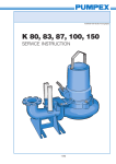
This service manual covers the pumps K89, K 103 and K 153 in following designs:
Type F Wet Pit Installation
Installed on a guide rail system with a quick-release base elbow, the base elbow is
bolted to the floor of the sump. The volute is equipped with an adapter to be connected to the discharge elbow. Two twin guide rails are mounted to the discharge
elbow to steer the pump into right position when hoisted up and down.
Type T, Dry Pit Installation
Installed in a normally dry well, but still fully submersible. The pump is supported by
an adjustable fabricated steel stand, mounted at the factory. The height of the stand
is sufficient for the standard suction elbow to be used on a flat floor. The pump volute
is drilled or threaded on the connection-flange and equipped with studs on the suction
flange. The motors are equipped with a maintenance-free internal, closed loop
cooling system which dissipates the heat to the liquid that is being pumped.
Type P, Wet Pit Portable or fixed installation
A version of pump which is suitable for temporary or permanent installations. The
pump is equipped with a fabricated steel stand and either a threaded (BSP, NPT) or
plain hose connection. The motor can if required, be equipped with a maintenancefree internal, closed loop cooling system which dissipates the heat to the liquid that is
being pumped.
When installed without a cooling jacket, the minimum
water level in the wet well for continuous operation
should not be below the top edge of the pump house.
Intermittent operation down to a water level above half
the height of the stator is acceptable, see picture. For
continuous operation at water levels below the top
edge of the pump house, an internal cooling jacket is
recommended.
The pumps are divided into three categories:
Standard, Ex and Fm. The difference between the
three is the wear plate. In the standard version there is
a hole drilled for the moisture switch. On the Ex there
is no hole and the Fm version has a threaded hole.
The Volute
The volutes are equipped with adjustable wear rings as standard. The volute on the
K89 is only available in the Vortex impeller design and has got no wear rings.
K 80
20 m
No 99999999
U 400 V
I 5,4 A
Y
1
2
3
4
P.2
2.0 kW 5
n 1385 rpm
6
3 Ph
Class F
50 Hz 7
IP68 8
98 kg 9
Box 5207 S - 12116 JOHANNESHOV SWEDEN
2 (10)
1
2
3
4
5
6
7
8
9
Type of pump
Serial number
Working voltage
Rated current
Rated output
Engine speed
Frequency
Winding class
Weight
SERVICE INSTRUCTION
K 89, 103, 153
K 89, 103, 153.58.0404.Eng/Digital
Warning !
The pump and its electrical cables must be disconnected from any power source by a qualified
electrician before any inspection or service is
performed!
Removal from the wet well
Hoist the pump from the sump and rinse clean.
Disassembling the volute
The rotating element is connected to the volute with
four latch bolts. Loosen the locking screws and turn the
latch bolts 90o. Lift out the rotating element from the
volute.
Changing the oil
Remove the plug marked ”outlet” and let the old oil
pour out through the groove under the plug. Discard of
any used oil in accordance with local regulations.
Fasten the plug so that the lower but not the top O-ring
gasket seals.
Oil: white oil (Enerpar M002, or similar).
Oil amount: 1.5 dl.
Inspect the motor housing by removing the screw
marked ”motor”. Tilt the pump slightly. If water, oil or
other debris is present in the motor housing, a full
dismantling is required.
M
OT
OR
L
OI
OI
L
Changing the cooling liquid
Pump without cooling jacket:
Loosen the cooling liquid plug down on the oil housing.
Open the plugs on top of the oil housing and let the old
water can pour out.
M
ET
INL
OT
OR
OI
L
Replug the lower plug on the oil housing. Slowly fill the
new cooling liquid into one of the holes on top of the oil
housing. Let both plugs on the top be open to avoid air
bubbles to obstruct the filling.
Note! Don´t forget to tighten the plugs after completed filling.
Cooling liquid, quantity (l): 4,0
(30% Propylene glycol DOWCAL ® 20)
Oil drain
3 (10)
SERVICE INSTRUCTION
K 89, 103, 153
K 89, 103, 153.58.0404.Eng/Digital
Pump with cooling jacket:
Loosen the cooling liquid plug down on the oil housing. Open
the plug on top of the cooling jacket and let the old water can
pour out.
Replug the lower plug on the oil housing. Slowly fill the new
cooling liquid into the hole on top of the cooling jacket.
Note! Don´t forget to tighten the plugs after completed filling.
Cooling liquid, quantity (l): 11,0
(30% Propylene glycol DOWCAL ® 20)
Disassembling the impeller
The impeller is bolted to the shaft with a washer and a bolt.
Securing the impeller, remove the impeller bolt with a wrench.
Disassembling the seal cartridge
Disassemble volute and impeller as above, and empty the
motor of cooling liquid and oil. Lay the rotating element on its
side. Remove the four screws that holds the seal cartridge. The
cartridge can be removed from the oil chamber by inserting the
set screws into the "jacking holes" in the cartridge, which will
force the cartridge from the housing.
Disassembling the connection cover
Remove the four screws that holds the cover. Gently lift the
cover to gain access to the terminal board area.
Note! Remember the order of the colours connected on the
terminal board.
Disassembling the cooling jacket
Disassemble the connection cover as above. Remove the four
screws that holds the jacket and lift it off.
Changing the stator unit
If the motor protection trips repeatedly, the stator has to be
overhauled. Disassemble the cable cover with the motor cable.
Check the isolation resistance with a megger. If measuring with
a 500 V megger the isolation resistance shall exceed 1 megaohm. This applies to phase to phase readings, as well as
between each phase to ground. If the isolation resistance is less
than 1 megaohm the stator should be cleaned and baked in an
oven. Also check the circuit with the three built-in thermal
overload switches using a buzzer or a bell.
4 (10)
SERVICE INSTRUCTION
K 89, 103, 153
K 89, 103, 153.58.0404.Eng/Digital
If the isolation resistance is less than 1 megaohm the stator has
to be checked. Disconnect the pump from the electric box.
Check the isolation resistance of the motor at the loose end of
the cable. Use a megger. If using a 500 V megger the isolation
resistance shall exceed 1 megaohm. phase to phase readings
as well as between each phase to ground.
If any problems occurs, disconnect the cable from the stator and
measure directly at the stator. If the isolation resistance is less
than 1 megaohm the stator should be dried in an oven.
If the circuit is open, probably one of the overload switches is
defective and should be located by testing each one.
The defective switch is bypassed according to the adjoining
connection scheme. If the stator still can´t be used it has to be
replaced. Disconnect the stator from the outgoing cables and
disassemble it. Order a exchange stator unit from the nearest
Pumpex Service Center.
Disassembling the stator
Remove the four screws that holds the stator casing. Gently,
with a hoist, lift the stator casing from the shaft. Disasssemble the
coupling cover and remove the connection plate. Put the stator
unit on a distance tube. Take the pressure tool from withunder
and put it on the stator. Push through the top bearing seat the
stator out from the casing.
Note! Make a note of the measure from the lower edge of the
stator housing to the edge of the stator, before the stator is
pressed out.
Disassembling the rotor and bearings
The rotor is mounted in the oil chamber with an upper and lower
bearing. Remove the four screws of the bearing house and
loosen the house with a crowbar. Carefully lift out the rotor with
the upper bearing from the oil housing.
Bearings that has been in contact with with water or that are
damaged should always be replaced. Fasten the rotor in a vice
with soft jaws. Clean the shaft and lubricate it. Place the
withdrawing tool on the upper bearing and see to that it pulls the
inner ring. If the lower bearing is on the shaft, pull it off with your
hands. Pick up the lower bearing if it´s still left in the oil housing.
5 (10)
Stator med
urpressningsverktyg
SERVICE INSTRUCTION
K 89, 103, 153
K 89, 103, 153.58.0404.Eng/Digital
Assembling
Clean all O-ring grooves and all other contact surfaces carefully.
Use a wire brush when necessary.
Lubricate all O-rings with oil or grease to prevent the O-rings
from getting stuck or damaged when remounted. Also lubricate
the threads on all the screws to facilitate disassembling when
serviceing next time.
Mounting the bearings
Check that the shaft is straight and that the key way isn´t
damaged. Polish eventual scratches and burrs off. Push the
upper bearing into its place. If a press isn´t available, heat the
bearing to 100-120o C in a oilbath.
Wipe off the shaft contacting surfaces of the bearing and mount
it. Place the bearing cover on the shaft and mount the lower
bearing by using only your hands. Don´t forget to refill the
bearings with grease.
Mounting the rotor in the oil housing
Push the lower bearing into the bearing seat by pushing lightly
with your hand at the end of the shaft. Lock the rotor by
fastening the four screws of the bearing house.
Mounting the seal cartridge
Put down the driving unit. Lubricate the shaftand all four O-rings
on the seal unit (three external on the seal housing and one
internal in the seal cap). Carefully push the seal unit onto the
shaft, and place into position by aligning the screw holes. Do not
use hard striking tools. Tighten the seal unit by fastening the
four screws.
NOTE! Never run the motor without having the impeller
mounted, if the seal is mounted. This can cause da-mage to
O-rings in seal.
Mounting the impeller
Turn the shaft so that the key way is upward. Put the key in its
groove and push the impeller onto the shaft. Lock the impeller
from rotating with a pipe or similar and fasten the impeller
washer and screw.
6 (10)
SERVICE INSTRUCTION
K 89, 103, 153
K 89, 103, 153.58.0404.Eng/Digital
Mounting the cable seal
If water has gottenthrough the cable seal to the terminal board,
the cable seals have to be replaced. The cable seal should be
replaced after every disassembly of the cable gland. Measure
the cable diameter with a slide gauge and compare it to the
holes in the cable seal and the spacers so that the dimensions
are alike.
Pull the seal onto the cable with one washer on each side. Pull
the cable through the cover so that the cable with its cover
extends through the cable gland an into the terminal area when
tightening the cable lead-in. After tightening, the strain relief
clamp is fastened. Turn the clip´s long pin down to prevent that
the cable lead-in from unthreading.
Mounting the stator
Push the stator in with the pressure tool. Note! Remember the
measure from "Dismounting the stator".
Pull the cables from the stator through the cable seals on the
connection plate. Put the connection plate with O-ring in their
place and connect the cables onto the terminal board according
to the wiring diagram on page 9.
Mount the connection cover. Erect the oil housing and clean all
contact surfaces between the oil housing and the stator unit with
a wire brush. Lubricate and mount a new O-ring on the oil
housing. The stator is now ready to be mounted on the oil
housing. Lift the stator unit with a lift device and carefully lower it
over the rotor. See to that the rotor does not damage the
windings or the stator stick. Fasten the stator with its six screws.
Be sure to that the external markings are in line.
Mounting the coupling cover
Keep the cover near the terminal board to not get the cables too
long. Connect the cables according the wiring diagram on page
9. Remember that the ground cable by safety reasons should be
longer than the other cables.
Before the cover is fastened, it should be turned one half turn to
avoid having the cables pinched under the cap.
'
Mounting the cooling jacket
Put the two internal cooling tubes into position and fix with the
external cooling pipe. Lower the cooling mantle over the stator
casing and see to that the external markings are in line, and that
the cooling pipes are in their right positions. Fasten the cooling
jacket with four screws. See that the external markings are in
line.
7 (10)
Stator med
inpressningsverktyg
SERVICE INSTRUCTION
K 89, 103, 153
K 89, 103, 153.58.0404.Eng/Digital
Mounting the rotating element to the volute
Turn the latch bolts so that the driving unit is free down to the
upper edge of the volute. Turn the latch bolts in and fasten
the screws alternately. See to that the external markings is in
line. Tighten completely by hand using the wrench supplied
by Pumpex. Once hand tightened, use a sledge hammer and
tighten by another ¼ to ½ turn to assure a tight connection.
Adjusting the wear ring
Lay the pump down on its side and check the clearance
inbetween impeller and wear ring. The clearance should be
0,7 mm maximum. The wear ring is placed on the bottom
side of the volute and is fastened by three screws placed
horizontally. Loosen these screws and adjust with the three
vertically placed screws. When necessary strike carefully
with a hammer or plastic club. When the distance is adjusted
the horizontally placed screws can be tightened.
Note! This applies only if using channel impeller. If using
vortex impeller do not adjust the wear ring!
The K89 does not have a wear ring due to the vortex design.
Testing
Connect the cables to the electric mains and start the pump.
This should only be done by a qualified electrician. The arrow
on the cover indicates the direction of rotation - clockwise,
when viewed from the top of the motor. The starting reaction
will be in the opposite direction.
8 (10)
SERVICE INSTRUCTION
K 89, 103, 153
K 89, 103, 153.58.0404.Eng/Digital
Wiring diagram
Y
D
351195 AA
230 V Yp
351188 AA
351189 AA
351194 AA
460 V Ys
351183 AB
351184 AB
351182 AB
351190 AB
351186 AB
351185 AB
351187 AB
Y/D
9 (10)
SERVICE INSTRUCTION
K 89, 103, 153
K 89, 103, 153.58.0404.Eng/Digital
Isolation resistance diagram
Tightening factor
Size
(Nm)
Size
(Nm)
M6
M8
M10
M12
M14
M16
7
17
33
57
91
140
Impeller bolt
(M12 Bumax)
115
Latch bolt
(M16 A4-80)
187
Cable gland: A specific estimation of the
tightening factor can not be given
for the cable gland. Tighten it until
the rubber offers resistance, and
thereafter one more full rotation.
10 (10)