1
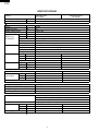
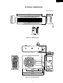
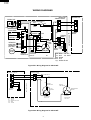
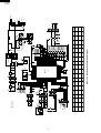
AH-A129E
AU-A129E
SERVICE MANUAL
S2918AHA129E/
SPLIT SYSTEM
ROOM AIR CONDITIONERS
INDOOR UNIT
MODELS
AH-A129E
OUTDOOR UNIT
AU-A129E
In the interests of user-safety (Required by safety regulations in some
countries) the set should be restored to its original condition and only
parts identical to those specified should be used.
TABLE OF CONTENTS
Page
SPECIFICATIONS ............................................................................................................................................ 2
EXTERNAL DIMENSIONS ................................................................................................................................ 3
WIRING DIAGRAMS ......................................................................................................................................... 4
ELECTRICAL PARTS ....................................................................................................................................... 5
MICROCOMPUTER CONTROL SYSTEM ........................................................................................................ 8
FUNCTIONS ..................................................................................................................................................... 9
REFRIGERATION CYCLE .............................................................................................................................. 13
PERFORMANCE CURVE ............................................................................................................................... 15
DISASSEMBLING PROCEDURE ................................................................................................................... 16
TROUBLESHOOTING OF THE CONTROL CIRCUIT .................................................................................... 21
REPLACEMENT PARTS LIST ........................................................................................................................ 24
SHARP CORPORATION
1
AH-A129E
AU-A129E
SPECIFICATIONS
ITEMS
Cooling capacity
kW
Moisture removal
Liters/h
Electrical data
Phase
–
Rated frequency
Hz
Rated voltage range
V
Rated voltage
V
Rated current
Cool
A
Rated input
Cool
W
Compressor
Type
Model
Oil charge
Refrigerant system Evaporator
Condenser
Control
Refrigerant volume
Capillary tube size Outer dia. mm
Inner dia. mm
Lenght mm
Q'ty
Noise level
High
dB(A)
Med.
dB(A)
Low
dB(A)
Fan system
Drive
Air flow quantity High
m3/min.
(at cooling)
Med.
m3/min.
Low
m3/min.
Fan
Connections
Refrigerant coupling
Refrigerant tube size Gas, Liquid
Refrigerant pipe sets No.
Drain piping mm(Inches)
Others
Safety device
INDOOR UNIT
AH-A129E
3.45
1.3
OUTDOOR UNIT
AU-A129E
Single
50
198 to 264
220 - 240
5.3 - 5.1
1150 - 1180
Hermetically sealed rotary type
RH207VXET
520cc (DIAMOND MS56))
Louver fin and Grooved tube type(7mm tube)
Louver fin and Grooved tube type(7mm tube)
Capillary tube
940g
–
2.7
–
1.6
–
700
–
1
42
48
40
–
36
–
Direct drive
9.3
8.4
7.0
Cross flow fan
Direct drive
26
–
–
Propeller fan
Flare type
1/2", 1/4"
AZ-24T7F; 7m(23ft)
O.D ø 18(45/64)
Compressor: Overload protector(Internal)
Fan motors: Thermal fuse
Fuse, Micro computer control
Air filters
Polypropylene net (Washable)
Net dimensions
Width
mm
897
720
Height mm
297
535
Depth
mm
186
236
Net weight
kg
10
35
Note: The condition of star( ) marked item are 'IEC378'.
2
AH-A129E
AU-A129E
EXTERNAL DIMENSIONS
Length unit (mm)
186
297
897
58
182
19.5
Remote controller
Figure E-1. INDOOR UNIT
245
58
535
236
228
430
720
775
3
278
143
Figure E-2. OUTDOOR UNIT
20˚
55
AH-A129E
AU-A129E
WIRING DIAGRAMS
INDOOR UNIT
TERMINAL BOARD 2
RE
RE
WH
TRANSFORMER
SWITCH CN201
UNIT
BCN
CN7
RECEIVER
& LED UNIT CN101
CN6
THERMISTOR
(ROOM TEMP.)
THERMISTOR
(PIPE TEMP.)
LOUVER
MOTOR
CN4
1
2
3
4
5
6 CN5
BL
NR
VARISTOR
(B)
1
1
TERMINAL
BOARD
G(Y)
G(Y)
TERMINAL
BOARD 1
G(Y)
INTERNAL
THERMAL
FUSE
R.P.M
SIGNAL
CN3
N
SSR
(A) (C) 5 3 1 CN2
RE
BL GR
N
BK
FUSE
T2.5A
CN8
BK
BL
FAN MOTOR
CONTROL
CAPACITOR
BOARD UNIT 2 430V 2µF
BR
BL
L
N
BR
BL
POWER
EVAPO- SUPPLY
RATOR CORD
FAN MOTOR
BK
BL
BR
GR
G(Y)
BL
: BLACK RE : RED
: BLUE
WH : WHITE
: BROWN
: GRAY
: GREEN–YELLOW
Figure W-1. Wiring Diagram for AH-A129E
INDOOR UNIT
TERMINAL BOARD 2
OUTDOOR UNIT
TERMINAL BOARD
G(Y)
1
1
N
N
TERMINAL
BORAD 1
BK
BK
BL
N
L
CONDENSER
RE INTERNAL
THERMAL FUSE
UNIT TO UNIT CORD
WH
CONTROL BOARD UNIT 1
RY
250V
IN
OUT
5
7
1 CN1
2
UNIT TO UNIT CORD
THERMAL FUSE
OUTDOOR UNIT
C
COMPRESSOR
MOTOR
FAN
MOTOR
S
R
BL
BK
BK :BLACK
BL :BLUE
G(Y) :GREEN-YELLOW
RE :RED
WH :WHITE
MOTOR
PROTECTOR
FAN MOTOR
CAPACITOR
430V 1.5µF
BL
Figure W-2. Wiring Diagram for AU-A129E
4
WH
RE
RUNNING
CAPACITOR
400V 30µF
AH-A129E
AU-A129E
ELECTRICAL PARTS
DESCRIPTION
Compressor
Indoor fan motor
Outdoor fan motor
Indoor fan motor capacitor
Outdoor fan motor capacitor
Running capacitor
Transformer
Fuse
MODEL
RH207VXET
ML-A525
ML-A593
–
–
–
–
REMARKS
220/240V, 50Hz, 1000W
220 - 240V, 50Hz, 220V, 60Hz
220/240V, 50Hz, 220V, 60Hz
430V, 2µF
430V, 1.5µF
400V, 30µF
Primary; AC 220/240V, 50Hz
SITE
AU
AH
AU
AH
AU
AU
AH
–
Secondary; AC14.5/15.9V, 50Hz
250V, 2.5A
AH
5
33µ
3
2
12H / 24H
19
(P41)
JP10
X NONE
IC1 PIN NO.
SYMBOL
SET
LOUVER MOTOR
FUNCTION
R6
470
1/2w
RY1
5
12V
X NONE
JP9
17
(P43)
OFF/ON
X NONE
JP7
16
(P44)
3/5min.
X NONE
JP5
15
(P45)
DEICE
B
2
2
D. FAN OFF OFF WIDEH
CN3
1
2
3
4
1
6
5
BCN
R28 680
1
6
5
R26
680
R30
10k
R29 330
5V
C13
1000P
50v
R41 10k
8
IC4
X NONE
JP4
14
(P46)
DEICE
A
9
12V
C23
1000P
50v
C17
1000P
50v
POWER ON
R40 10k
5V
CN8
5
5
(RED) LED101
SSR
4
4
(YELLOW) LED102
12V
3
12V
2
3
(C102)
0.1µ
25v
2
CN6
1
1
CN101
2
2
1
– 10v
+ C101
3
3
1
PHOTO DETECTOR UNIT
(TEST RUN)
AUX.
CN7
CN201
5V
FREEZE A
FREEZE B
DE. FAN A
DE. FAN B
NC
JP8
SM8313
19
P06
IC1
JP2
JP1
USE
X NONE
5
(P33)
OFF/ON
6
(P32)
C7
0.1µ
50v
WIRELESS
CHANG/
NORMAL
–
+
PREHEAT
C8
10µ
10v
5V
6
5
4
3
2
1
P33
P50
P51
P52
P53
R9
3.9k(F)
2.7k(F)
3
(P51)
FAN M
7
P32
R10
4
(P50)
FAN L
8
P31
9
10
11
P30
AGND
CK2
CK1
RESET 12
5V
2.7k
R8
2
(P52)
FAN H
R39 10k(F)
R38 10k(F)
R37 10k(F)
R36 10k(F)
R35 10k(F)
10k
10k
10k
R34
R33
R32
R31
2
1
2
Q1
5V
TR
1.2k(F)
R12
1
(P53)
R11
R12
R8
R9
R10
JP2
JP1
JP3
JP6
12V
2
SWEAT
1
7.32k(F)
R11
64
(P54)
5V
X NONE
JP14
33
(P27)
R20
10k
X NONE
JP13
34
(P26)
DE. FAN
A
C22
1000P
50v
C21
1000P
50v
R25
1.2k
FUSE
2.5A 250V
X NONE
JP12
35
(P25)
C11
10µ
C10
10µ
X NONE
JP11
36
(P24)
FREEZE
A
– 16v
+
– 16v
+
FAN MOTOR
R17
15kF
R18
15kF
R19
10k
FREEZE
B
CN5
3
2
1
CN1
5
3
1
THERMAL
PROTECTOR
R21
10k
12V
D9
A
C
11
CNR3
5V
13
R5
2.7k
R23
33k
R24
4.7k
DE. FAN
B
MODEL A
MODEL B
FAN H
FAN M
FAN L
WIRELESS
PREHEAT
MODEL
A
L
S201D01
SSR
FAN MOTOR
CAPACITOR
IC5
BZ
F
C12 0.01µ 250vAC
C19
1000p
50v
C15
0.1µ
50v
3
NR
G
RPM PLUSE
5V
3
OCS
DEICE B
DEICE A
12H/24H
D. FAN OFF
OFF WIDEH
RPM
C1
0.1µ
250vAC
8MHz
MODEL
B
3
1
7
5
CN2
10k
JP4
JP5
JP7
JP9
JP10
C18
1000P
50v
R7
3.3k
2
1
CN2
Figure L-1. Electronic Control Circuit Diagram
USE
JP3
7
(P31)
RPM
PLUSE
1/3
P07
51
P11
48
50
P12
47
P10
P13
49
P14
P16
P15
43
P17
K1
P20
42
41
40
14
13
15
P46
F
P45
P22
38
P21
P23
37
39
P44
P24
16
17
18
1
2
R3
22k
Q3
BCN
7
3
CN8
7
36
P43
P41
P42
NC 46
X NONE
JP6
8
(P30)
5V
C14
0.01µ
16v
P25
NC 45
SWEAT
R4
6.8k
C16
0.1µ
50v
D4
D3
R2
22k
D2
THERMAL FUSE
D1
P26
NC 44
ON/OFF
NC
R22
1k
5
6
7
8
5V
–
+
35
P27
IC6
CN8
C3
0.22µ
50v
C2
2200µ
35v
34
33
4
3
2
NC
1
NC
BCN
JP11
JP12
JP13
JP14
10V
47µ
– 25v
IN
P05
52
5V
4
IC2
P04
53
4
OUT
P03
NC 54
–
TEST 32
+ C4 GND
29
3
OCS IN 30
P02
NC 55
3
28
P60
P01
NC 56
C5
0.1µ
50v
27
P61
P00
NC 57
IN
26
P62
GND
58
IC3
25
GND
VDD
59
GND
24
P63
VR
60
OUT
23 NC
P64
P57
61
+
22 NC
P65
P56
C6
100µ
10v
OCSOUT 31 NC
7812
21
KH
P66
P55
62
NOTE :
1.
: TEST POINT
2. Not specified is 1/5w
12V
20
P40
P54
63
6
64
5V
5V
IN
PIPE TEMP.
X NONE
JP8
40
(P20)
ON/OFF
15k(25˚C)
ROOM TEMP.
TH2
1
N
POWER
SUPPLY
OUTDOOR UNIT
NEUTRAL LINE
EARTH LINE
GREEN/YELLOW
TERMINAL
BOARD 3P
15k(25˚C)
OUT
TEST
TH1
POWER ON
CN4
6
5
4
3
2
1
RY1
B
L
N
AH-A129E
AU-A129E
7
FUSE
Figure L-2. Printed Wiring Board
(FAN MOTOR)
CN2
DIP
C16
1
1
IN
CN4
C5
6
GND
3
JP32
OUT
IC3
C19
JP35
AUX
1
CN201
SW102
SW101
3
C21
C22
C18
(THERMISTOR)
C10
C11
R19
R18
R17
R15
C9
Q3
1 R16
QPWBFA891JBE0
TEST
RUN
DPWBFA047JBK0
D7
From louver
CN3
From fan motor
R25
To
Fan motor
capacitor
(C)
F.M. GRAY
CAP
1
C1
(RPM)
250V 2.5AT
5
JP16
CN5
5
( LOUVER )
MOTOR
(F) BROWN C12
(B)
N
CN7 BZ
3
1
1
12V
BLUE
1
D9
N BROWN
L
L
NR
(G)
JP19
JP18
From
Terminal
board " L "
OUT
RY1
F.M.
CAP
(A)
BLUE
7
BCN
R14
R13
CT
Q2
C6
32
R4
R24
D6
From
Terminal
board " 1 "
1
R6
5V
CN8
JP20
R5
33
20
JP36
3 (E)
R40
3
R28
R29
JP21
GND
JP22 R41
CN6
1
SWEET
12V
JP29
7
JP23
C4
(D)
CNR2
ORANGE
JP31
JP17
1
3
JP25
JP24
5
R.P.M.
IC4
16
C13
1 C17
OSC
JP15
1
JP28
JP27
JP26
51
19
3 IC5
1
JP12
JP11
JP8
9
8
52
IC1
2
POWER ON
CN1
R30
(TRANSFORMER)
1
64
1
JP33
QPWBFB253JBE0(C)
REEZE B
REEZE A
2
PURPLE
RY2
RY3
C23
Q1
C20
3
R26
C8
R39 JP30
QPWBFB
126JBE0
C101
PHOTO DETECTOR UNIT
LED101(RED)
M.B.
JP14
JP13
DEF FAN A
To
Fan motor
capacitor
7
C3
C2
OUT
IC2
F.H.
C7
GND
IN
CN101
M.A.
RECEIVER
1
R8
R12
LED102
(YELLOW)
DPWBF
A092
JBK0
R37
From
Transformer
QPWBFB253JBE0(P)
5
R38
R22
JBK0(P)
R11
DE FAN B
DPWBFA
F.M.
D3
D1
WIREL
IC6
DIP
OFF WIDEH
R2
R3
PREH.
D4
D2
R31
JP6
R32
JP3
R33
JP1
R34
JP2
JP35
R10
R36
R9
JP7
JP9 D. FAN OFF
D5
C15
CNR1
JP34
2
DEICE A
R21
SSR
DEICE B
JBK0(C)
13
JP5
JP4
R23
R7 C14
1
TIMER
DPWBFA
CNR3
JP10
R20
7
DSGY-A878JBK0
From
Thermistor
AH-A129E
AU-A129E
AH-A129E
AU-A129E
MICROCOMPUTER CONTROL SYSTEM
Microcomputer (IC1)
The microcomputer is a CMOS, one chip, 8-bit microcomputer.
Microcomputer port allocation is as follows.
Pin
No.
1
2
3
4
5
6
7
8
9
10
11
12
13
14
15
16
17
18
19
20
21
22
23
24
25
26
27
28
29
30
31
32
Terminal
Name
P53
P52
P51
P50
P33
P32
P31
P30
AGND
CK2
CK1
RESET
F
R46
R45
R44
R43
R42
R41
R40
KH
P66
P65
P64
P63
GND
P62
P61
P60
OSC
OSC
TEST
Input
Output
IN
IN
IN
IN
IN
IN
IN
IN
IN
IN
IN
IN
OUT
IN
IN
IN
IN
IN
IN
IN
IN
IN
IN
IN
IN
IN
IN
OUT
IN
IN
OUT
IN
Pin
No.
33
34
35
36
37
38
39
40
41
42
43
44
45
46
47
48
49
50
51
52
53
54
55
56
57
58
59
60
61
62
63
64
Function
MODEL B
FAN H
FAN M
FAN L
WIRELESS
PREHEAT
PRM PLUSE
SWEAT
0V
OSILLATION
OSILLATION
RESET
BUZZER
DEICE A
DEICE B
COMP. OFF WIDTH
DEHUM. FAN OFF
TEST 1
–
–
PRM SIGNAL
–
–
–
AC CLOCK
0V
–
EEPROM CLOCK
EEPROM DATA
–
–
–
8
Terminal
Name
P27
P26
P25
P24
P23
P22
P21
P20
KI
P17
P16
P15
P14
P13
P12
P11
P10
P07
P06
P05
P04
P03
P02
P01
P00
GND
VDD
VR
P57
P56
P55
P54
Input
Output
IN
IN
IN
IN
IN
IN
IN
IN
IN
OUT
OUT
OUT
OUT
OUT
OUT
OUT
OUT
OUT
OUT
OUT
OUT
OUT
OUT
OUT
OUT
IN
IN
IN
IN
IN
IN
IN
Function
MODEL 4
MODEL 3
MODEL 2
MODEL 1
SWITCH AUX.
SWITCH TEST RUN
–
POWER ON
WIRELESS SIGNAL
LED OPERATION
LED TIMER
–
–
(VALVE COIL)
(OUT DOOR FAN)
RY1
SSR
LOUVER MOTOR
LOUVER MOTOR
LOUVER MOTOR
LOUVER MOTOR
–
–
–
–
0V
5V
5V
(CURRENT LEVEL)
TH1
TH2
MODEL A
AH-A129E
AU-A129E
FUNCTIONS
2. Operation modes
2-1 COOL operation
The compressor turns on or off, at the
thermostat lines C3 and C4. The outdoor fan
motor is also controlled with the compressor.
34.5
C1
33.5
C2
32.5
C3
31.5
C4
States 1 & 3 : Compressor ON
State 2 : Compressor OFF
Room temperature
Room temperature( C)
1. Temperature control characteristic
1-1 COOL operation
In the “COOL” mode, the thermostat circuit is
controlled by four thermostat lines (C1 thru C4).
20.5
19.5
C3
Room
temperature
transition
18.5
2
17.5
18
32
Preset temperature(˚C)
Preset temperature
Figure H-3
Figure H-1
2-2
DRY operation
In the “DRY” mode, the thermostat circuit is
controlled by three thermostat lines (D1 thru
D3).
33.5
D1
32.5
D2
31.5
D3
19.5
18.5
17.5
18
Preset temperature(˚C)
32
DRY operation
On the switch on, the compressor always starts
to operate for 2 minutes with fan speed “D”
(slower than “UL”).
The microcomputer measures the room
temperature 2 minutes after this first compressor
operation. This room temperature is set as the
preset temperature automatically. The preset
temperature ranges from 18˚C to 32˚C. When
the room temperature is below 18˚C, the preset
temperature is set to 18˚C, and when the room
temperature is over 32˚C, the preset
temperature is set to 32˚C
Dry operation is divided into three zones
(Cooling zone, Dehumidifying zone and
Circulating zone) by thermostat lines (D1 to
D3), and the compressor and the fan motor
are controlled in each zone as shown in Table
H-1.
States 1 & 5 : Cooling zone
States 2 & 4 : Dehumidifying zone
States 3 : Circulating zone
Figure H-2
D1
Room temperature
Room temperature( C)
1-2
C4
3
1
D2
5
D3
1
4
2
3
Room
temperature
transition
Preset temperature
Figure H-4
9
AH-A129E
AU-A129E
Table H-1
7. Timer
7-1 24-HOUR PROGRAMMABLE ON/OFF TIMER
ON-TIMER or OFF-TIMER can be independently
programmed. When the unit operates during one
hour after the OFF-time is set, thermostat setting
is automatically shifted (+1˚C in cool operation
and dry operation, -3˚C in heat operation, but,
16˚C set temperature at the lowest).
When the ON-timer is set in heat operation and
cool operation, operation starts before 0 to 30
minutes(depends on the room temperature) so
that preset temperature is obtaind at set time.
Compressor Fan speed
Cooling zone
ON
"UL"
Dehumidifying zone
ON
"D"
Circulating zone
OFF
"D" or OFF
2-3
Fan only operation
The indoor fan motor always turns on.
3. Fan speed
Fan speeds are given by the indoor fan motor, “H”,
“M”, “L” and “UL”, which are available in the following
operation mode.
7-2 ONE-HOUR TIMER
When ONE-HOUR timer is set, the unit turns off
automatically after one hour. The one hour timer
operation has priority over other time operation,
such as the TIMER ON and TIMER OFF. If the
ONE-HOUR TIMER button is pressed again
during operation, the unit will operate additionally
for another one hour.
Table H-2
FAN Switch
HIGH
LOW
SOFT
COOL
M
L
UL
FAN ONLY
M
L
UL
8. Automatic air conditioning
When automatic air conditioning is selected, the
operation mode and preset temperature are set
automatically according to the room temperature on
starting operation.
4. Anti-sweating
When the operation continues 30 minutes in cooling
zone or dehumidifying zone during dry operation or
in continuous compressor operation during cool
operation, the fan speed of indoor fan motor shifts
up, from “UL” to “L” or from “D” to “UL”.
Table H-3
Room temp. of
operation start
5. Freeze preventive
When the indoor pipe temperature falls below -1˚C
during cool operation or dry operation, the compressor
is stopped.
Above 28˚C
26˚C to 28˚C
24˚C to 26˚C
Below 24˚C
6. Test run
If the “TEST RUN” button in the unit is pushed during
suspension of operation, cool test operation starts. At
this time, the fan speed is set to “AUTO”. If this button
is pushed during operation, the test operation starts
in current operation mode. The operation LED (red)
flickers during test run. During cool operation and
heat operation, the compressor is kept on but in dry
operation it is set in the dehumidifying zone. In fan
only mode the indoor fan motor runs continuously.
Operation
start
COOL
DRY
Preset
temp.
26˚C
25˚C
24˚C
Room temp. at
operation start
9. Automatic fan speed
When the automatic fan speed is selected in cool or
heat operation, the fan speed is automatically changed
by the thermostat lines C1 to C3 in cool operation
and H1 to H4 in heat operation.
Room temperature
States 1 & 5 :"M"
States 2 & 4 : "L"
States 3 : "UL"
5
C2
C3
1
4
2
3
Room
temperature
transition
Preset temperature
Figure H-5
10
C1
AH-A129E
AU-A129E
10.Power on start
If the connecting wire "POWER ON" is cut on the
PWB ass’y, when the power is supplied by turning
on a circuit breaker, the air conditioner automatically
starts of operation in “AUTO” mode.
(Refer to Figure L-2. Printed Wiring Board.)
11.Auto restart
Power failure occurs during operation, the unit will
restart in the same operation mode as before after
power recovery.
(Refer to Figure L-2. Printed Wiring Board.)
12.Outputs in each operation mode
Table H-4
COOL
DRY
Compressor
Outdoor
Fan motor
Indoor
Fan motor
Cooling
ON
ON
ON
Circulating
OFF
OFF
ON
Cooling
ON
ON
L/UL
Dehumidifying
ON
ON
UL/D
Circulating
OFF
OFF
D/OFF
OFF
OFF
ON
FAN ONLY
13.Diagnosis procedure
When indoor fan motor is out of order or compressor lock occurs, the compressor, inddor fan motor, outdoor fan
motor, and louver are all stopped and the operation LED(red) turns on or off syncronously with the timimg of the
timer LED.
When the thermistor for room temperature or pipe temperature is open or short state, the operation LED turns on
or off syncronously with the timing of the timer LED by pushing continously for more than three seconds both
"TEST" button and "AUX." button.
1sec.
Timer
LED
Indoor
fan motor
Operation
LED
Comp.-lock
Operation
LED
1sec.
ON
4sec.
OFF
ON
OFF
ON
OFF
Thermistor
short state
Operation
LED
ON
Thermistor
open state
Operation
LED
ON
OFF
OFF
Timing chart of Timer LED and Operation LED of DIAGNOSIS PROCEDURE.
When "OI" button the remote controller or "AUX." button in the unit is pushed, the unit is free from DIAGNOSIS
PROCEDURE.
11
AH-A129E
AU-A129E
14.Test mode
14-1 TEST 1 (For control circuit operation checking)
Make terminals 1 and 2 of connector CN4 short-circuited and supply power.
The timer's periods become shorter i.e. a 3 minute cycle is carried out in 3 seconds, except for ;
The operation LED flicker's period
in Test run
The protector timer
The defrost timer
not shortened
14-2 TEST 2 (For output of each operation checking)
Test mode is for checking output of each operation. Keep pushing both the buttons, "AUX." and "TEST
RUN", and supply the power, the system will go to the test 2 mode.
In this mode, the output of operation is switched by the "TEST RUN" button in the unit or the "OI" button in
the remote controller. Use the "AUX." button to back to step 1. Normal outputs are shown in Table H-5.
Table H-5
Lamps
Step
Output for outdoor unit
RED
YELLOW
Indoor
Fan motor
Louver
1
OFF
1
2
OFF
OPEN
2
ON
Flickering
ON
D
OFF
3
OFF
ON
OFF
M
OFF
4
OFF
ON
ON
L
CLOSE
5
OFF
ON
OFF
D
OFF
6
OFF
OFF
OFF
UL
OFF
7
OFF
OFF
OFF
H
OFF
8
OFF
OFF
ON
M
OFF
9
OFF
ON
ON
L
OFF
10
OFF
OFF
ON
OFF
OFF
11
OFF
ON
OFF
OFF
OFF
12
OFF
OFF
ON
OFF
OFF
13
OFF
OFF
OFF
OFF
OFF
14
OFF
ON
ON
OFF
OFF
15
OFF
ON
OFF
OFF
OFF
16
OFF
OFF
OFF
OFF
OFF
17
OFF
ON
ON
OFF
OFF
18
OFF
OFF
OFF
OFF
OFF
19
OFF
ON
OFF
OFF
OFF
20
OFF
ON
ON
OFF
OFF
21
OFF
ON
ON
OFF
OFF
22
OFF
OFF
OFF
OFF
OFF
23
OFF
OFF
OFF
OFF
OFF
3
(Back to step 1)
1 : 7˚C
: 7˚C
Room temp. 42˚C
(Room temp.) or (Room temp.)
2 : –2˚C
: –2˚C
Pipe temp. 42˚C
(Pipe temp.) or (Pipe temp.)
ON
OFF
42˚C
ON
OFF
42˚C
3 : ON in the case of Power on start
12
AH-A129E
AU-A129E
REFRIGERATION CYCLE
Indoor unit
Evaporator
3
Flare coupling
Flare coupling
Service port
Outdoor unit
Flare coupling
Flare coupling
Compressor
Capillary
tube
1
Accumulator
4
Condenser
2
S
Strainer
Figure R-1. Refrigeration Cycle
S
Figure R-2. Flow of Refrigerant
13
AH-A129E
AU-A129E
Cycle temperature and service port pressure
(ISC Cooling)
NO. Condition
1
2
3
4
Service port pressure
Cooling
81˚C
39˚C
13˚C
9˚C
0.53MPa
Gauge pressure
ISO Cooling T1 condition
Cooling
Indoor side
Temperature (˚C)
Relative humidity (%)
27
47
Dimension of Capillary tube
Capillary tube
O.D.
ø 2.7
I.D.
ø 1.6
L
700
14
Outdoor side
Temperature (˚C)
Relative humidity (%)
35
40
AH-A129E
AU-A129E
PERFORMANCE CURVES
4.5
13600
4.0
11900
(KW)
15300
3.5
3.0
8500
2.5
1500
Input(W)
10200
1000
500
15
14
Outlet air temp.(˚C)
Cooling capacity (BTU/h)
Indoor air temp. : 27˚C
Indoor humidity : 47RH%
Indoor fan speed : Hi
Power source : 1ø 220V 50Hz
13
12
11
10
9
8
7
30 31 32 33 34 35 36 37 38 39 40
Outside air temp.(˚C)
Figure P-1. At Cooling
15
AH-A129E
AU-A129E
DISASSEMBLING PROCEDURE
INDOOR UNIT
CAUTION: DISCONNECT THE UNIT FROM THE POWER SUPPLY BEFORE ANY SERVICING
1. Remove the 3 screw covers in the front panel.
4. Close the open panel softly, and then press B and C
of it securely.
Remove the front panel ass’y as to lift up.
B
B
C
2. Remove 3 fixed screws.
5. Loose a cord clamp screw and take it out.
3. Pull the open panel at A toward you.
Remove a fixed screw.
A
6. Loose 3 screws on the terminal board and take out
the unit-to-unit cord from it.
A
16
AH-A129E
AU-A129E
7. Take the thermistor holder from evaporator.
11.Loose 6 screws fixing control box and take out control
ass’y.
8. Take out the thermistor from evaporator.
12.Loose 2 screws fixing drain pan ass’y. (Left side)
9. Disconnect fan motor connectors and others.
13.Loose a screw fixing drain hose.
10.Loose 2 screws for a pipe cover and take it out.
Loose the earth screw.
14.When assembling, make sure that O ring is fitted to
the drain hose.
O-ring
Drain hose
O-ring
(Section)
17
AH-A129E
AU-A129E
15.Take out the drain pan ass’y.
19.Take out the fan bearing ass’y.
16.Loose a screw fixing cross flow fan to motor.
20.Take out the cross flow fan while slightly lifting the
evaporator.
17.Slide the cross fan leftward to depart from the motor
shaft and take out fan motor.
18.Loose 2 screws fixing evaporator.
18
AH-A129E
AU-A129E
FOR OUTDOOR UNITMODEL AU-A129E
CAUTION:DISCONNECT THE UNIT FROM THE POWER SUPPLY BEFORE ANY SERVICING
1
2
Remove the three(3) screws holding the right
side cover and take it out.
Remove the three(3) screws holding the left side
cover and take it out.
3
Remove the another screws holding the cabinet
and take it out.
NOTE: Number as shown in following figure is the re
moval order.
2
Left side cover
Condenser
Compressor
Bulkhead
Fan motor
Propeller fan
Cabinet
Right side cover
1
3
Fan guard
Figure D-1. OUTDOOR UNIT
19
AH-A129E
AU-A129E
TROUBLESHOOTING OF A CONTROL CIRCUIT
The machine does not function
at all with remote controller and
switches on the indoor unit.
Using a meter, measure the
voltage between anodes of D1
and D2 on the PWB ass'y 1.
Is the measured value
approx. 20.6 Vac ?
measure the secondary voltage
of transformer.
NO
YES
Replace the PWB with a new
one.
Is the 2.5A fuse
open circuit ?
NO
YES
Replace the fuse and varistor
with new ones.
20
Replace the transformer with
a new one.
AH-A129E
AU-A129E
The machine does not function
at all with remote controller
Push button "O/I" on the
wireless remote controller.
Is transmitting
indicator of the remote
controller active ?
NO
Are batteries of the
wireless remote controller
good ?
YES
Does beep sound
from the indoor unit ?
NO
Replace the batteries
with new ones.
YES
Replace the wireless
remote controller.
YES
NO
Does connector
CN103 connect in place ?
Is indicator lamp of
indoor unit proper ?
NO
YES
PWB is normal.
Inspect the outdoor unit.
NO
YES
Using a tester,
measure the voltage
between terminals
of resistor R30
on the PWB ass'y.
Connect the
connector
properly.
Replace the
PWB with a
new one.
When the signal is
received, does the voltage
change ?
YES
Push the button
"O/I".
Replace the PWB with a new
one.
21
NO
Replace the display unit
with a new one.
AH-A129E
AU-A129E
CHARACTERISTIC OF TH1 & TH2
K
180
The room is not cooled.
The compressor does not operate.
160
140
120
Push the button "TEST" on the
indoor unit, and wait 3 minutes.
100
80
10˚C
30K
60
Using a meter, measure voltage at
the terminals on the terminal board.
40
20
0
-10
Is there a voltage
between terminal "N" and
"1" of the terminal board the
power supply voltage ?
0
10 20
Fig. 1
30 40˚C
NO
Replace the PWB ass'y with a new one.
YES
Measure resistances of TH1 and TH2.
Are the resistances
correct Fig. 1 ?
NO
Replace the thermistor ass'y with a new one.
YES
The control circuit is normal.
The compressor may be defective.
The running capacitor may be defective.
Refrigerant may have leaked.
The outdoor fan motor may be defective.
The outdoor fan motor capacitor may be defective.
22
AH-A129E
AU-A129E
REPLACEMENT PARTS LIST [AH-A129E]
REF. NO.
PART NO.
DESCRIPTION
Q'TY
CODE
CABINET AND UNIT PARTS
1- 1
1- 2
1- 3
1- 4
1- 5
1- 6
1- 7
1- 8
1- 9
1-10
1-11
1-12
1-13
1-14
1-15
1-16
1-17
1-18
1-19
1-20
1-21
1-22
1-23
1-24
1-25
1-26
1-27
1-28
1-29
1-30
1-31
1-32
1-33
1-34
1-35
1-36
1-37
1-38
1-39
1-40
1-41
1-42
1-43
1-44
1-45
1-46
1-47
1-48
CMOT-A271JBK0
NFANCA041JBE0
CSRA-A445JBK0
MJNTPA035JBFF
MLOV-A115JBFE
MLOV-A116JBFF
MLOV-A171JBFE
PHOS-A015JBE0
PPACGA002JBE0
LHLD-A279JBF0
GGAD-A042JBEA
LHLD-A092JBFZ
RMOT-A073JBE0
CHLD-A067JBK0
PFPFPB038JBE0
LHLDW0365JBE0
PGUMMA056JBE0
PGUMMA082JBE0
DCHS-A356JBK0
DWAK-A780JBK0
PFILMA065JBEF
HDEC-B021JBEA
GCOVAA006JBFE
HBDG-A059JBEA
HPNL-A119JBTB
MARMPA006JBFA
MARMPA007JBFA
GWAK-A178JBFC
LHLD-A194JBF0
MARMPA008JBFA
MARMPA009JBFA
PGUMSA113JBE0
PCOV-A207JBE0
PFPFPA905JBE0
PFPFPA774JBE0
PGUMSA135JBE0
CPNL-A307JBK0
PCUS-A026JBE0
LHLD-A278JBE0
LHLD-A181JBFA
LHLD-A161JBF0
QW-VZC636JBE0
PSEL-B778JBE0
PSEL-B779JBE0
PSEL-B780JBE0
PSEL-B863JBE0
TSPC-C986JBRA
TLABCB257JBR0
Fan motorr sub ass’y
Cross flow fan
Drain pan ass’y
Louver link
Horizontal adjustment louver A
Horizontal adjustment louver B
Horizontal louver
Drain hose
O ring
Shaft holder
Wire guard
Louver holder
Louver motor
Bearing ass’y
Seal
Wire holder
Motor cushion
Motor cushion
Cabinet ass’y
Panel ass’y
Air filter
Decoration panel
Front panel cover
Badge
Open panel
Open arm L
Open arm R
Front panel
Panel center holder
Arm L
Arm R
Damper rubber
Drain cover
Panel insulator A
Cabinet insulator
Damper rubber
Open panel ass’y
Cushion 12
Guard holder
Pipe holder
Pipe holder
Fan motor lead
Aluminum tape
Aluminum tape
Aluminum tape
Aluminum tape
Name label
Wiring diagram
2- 1
2- 2
2- 3
2- 4
2- 5
2- 6
2- 7
2- 8
2- 9
2-10
2-11
2-12
2-13
2-14
2-15
2-16
2-17
2-18
2-19
2-20
2-21
2-22
2-23
DSGY-A878JBK0
DPWBFA047JBK0
QACC-A194JBE0
QTAN-A127JBE0
QTAN-A088JBE0
DPWBFA154JBK0
PSEL-B777JBE0
RTRN-A182JBE0
RC-HZA286JBE0
RTHM-A296JBE0
LHLD-A095JBF0
PBOX-A133JBF0
HPNLCA564JBF0
HPNLCA565JBEA
LHLD-A141JBFA
PSEL-B859JBE0
PSHE-A072JBE0
PSHE-A095JBE0
LHLD-A224JBFE
RH-IXA519JBE0
RH-IZA149JBE0
RIC--A022BDE0
RIC--A025BDE0
Display unit
Switch board unit
Power supply cord
Terminal board(3p)
Terminal board(3p)
COntrol board unit
Aluminun tape
Transformer
Fan motor capacitor
Thermistor
Thermistor holder
Control box
Control cover
Operation panel
Cord holder
Aluminun tape
Protect paper
Protect sheet
Cord clamp
Microcomputer(IC1)
Integrated circuit(IC2)
TIntegrated circuit(IC3)
Integrated circuit(IC4)
1
1
1
3
9
3
1
1
1
1
1
2
1
1
1
1
1
1
1
1
2
1
1
1
1
1
1
1
1
1
1
1
1
1
1
2
1
1
4
1
1
1
1
1
1
1
1
1
BN
BG
BN
AE
AB
AD
AN
AL
AA
AC
AN
AC
AU
AL
AB
AA
AN
AD
BD
AZ
AN
AL
AD
AF
AX
AC
AC
AX
AC
AC
AC
AE
AC
AA
AC
AB
AY
AC
AD
AC
AD
AG
AC
AB
AD
AC
AD
AD
1
1
1
1
1
1
1
1
1
1
1
1
1
1
1
1
1
1
1
1
1
1
1
AS
AP
AU
AN
AP
BN
AC
AY
AY
AN
AC
AG
AG
AG
AC
AC
AB
AB
AG
AX
AE
AE
AE
CONTROL BOX PARTS
23
AH-A129E
AU-A129E
REF. NO.
PART NO.
DESCRIPTION
2-24
2-25
2-26
2-27
2-28
2-29
2-30
2-31
RH-IZA140JBE0
RH-IZA337DRE0
VHRS201D01/-6
RRLYJA032JBE0
RFIL-A042JBE0
RH-VZA025JBE0
RC-QZA096JBE0
QFS-AA050JBE0
Integrated circuit(IC5)
Integrated circuit(IC6)
Solid state relay(SSR)
Relay
Coil(L)
Varistor(NR)
Capacitor(C1)
Fuse
3- 1
3- 2
CPIPCA402JBK0
PEVA-A248JBE0
Pipe assembly
Evaporator
4- 1
4- 2
4- 3
4- 4
4- 5
4- 6
4- 7
4- 8
4- 9
4-10
LX-NZ0247JBE0
CRMC-A490JBE0
TINS-A565JBR0
TINSEA221JBR0
PPLTNA020JBW0
FCOV-A013JBFA
XTTSD45P30000
LX-BZA106JBE0
TLABPA175JBR0
TINS-A566JBR0
Special nut
Wireless remote controller
Installation manual
Operation manual
Mounting angle
Screw cover
Tapping screw
Special screw
Louver label
Installation manual
6- 1
6- 2
6- 3
LX-BZA075JBE0
XREUW50-06000
XZPSD40P14000
Special screw
Ring
Special tap screw
Q'TY
CODE
1
1
1
1
1
1
1
1
AE
AK
AK
AU
AM
AD
AE
AD
1
1
BB
BT
7
1
1
1
1
3
6
1
1
1
AB
BG
AF
AR
AP
AB
AA
AD
AB
AD
1
2
4
AA
AB
AA
CYCLE PARTS
ACCESSORY PARTS
SCREWS AND NUTS
HOW TO ORDER REPLACEMENT PARTS
To have your order filled prompty and correctly, please furnish the following information.
1. MODEL NUMBER
3. PART NO.
2. REF. NO.
4. DESCRIPTION
24
AH-A129E
AU-A129E
1
2
3
4
5
6
INDOOR UNIT
A
A
1-35
4-2
4-5
4-4
B
1-40
4-7 4-8
4-1
B
1-41
4-3
4-10
1-15
2-13
2-2 2-17
2-12
2-10
3-2
C
1-19
2-7
2-14
C
3-1
2-18
2-9
2-7
2-11
2-10
1-38 1-32
2-8
6-1
1-46
2-15
2-16
D
1-39
1-33
1-36
D
2-4
1-11
2-1
1-3
2-3
2-5
2-19
1-10
1-16
1-14
1-5
1-6
1-2
E
E
4-9
1-12
1-42
1-4
1-7
1-8
1-12
1-1
1-18
1-17
1-9
1-30
1-23
1-21
F
1-13
1-43
F
6-3
1-31
1-26
1-29
1-25
1-48
G
G
6-2
1-45
1-28
1-20
1-27
1-44
1-34
1-24
1-37
1-47
4-6
1-22
H
H
1
2
3
4
25
5
6
AH-A129E
AU-A129E
REPLACEMENT PARTS LIST [AU-A129E]
REF. NO.
PART NO.
DESCRIPTION
Q'TY
CODE
1
1
1
1
1
1
1
1
1
1
1
1
1
1
1
2
1
1
1
BQ
AW
AP
AX
AR
AH
AR
BA
AY
AK
AZ
AE
AC
BH
AK
AK
AK
AK
AE
1
1
1
1
1
1
1
1
1
AD
AC
AP
BC
AX
AF
AC
AF
AR
1
1
1
1
1
1
1
1
1
1
1
1
3
3
1
1
1
1
1
1
1
CH
CA
BB
AE
AG
AB
BF
AH
AD
AD
AP
AG
AK
AB
AH
AD
AD
AE
AC
AE
AD
4
1
1
2
4
2
1
AB
AA
AB
AA
AA
AB
AD
CABINET AND UNIT PARTS
1- 1
1- 2
1- 3
1- 4
1- 5
1- 6
1- 7
1- 8
1- 9
1-10
1-11
1-12
1-13
1-14
1-15
1-16
1-17
1-18
1-19
CMOTLA593JBE0
NFANPA020JBEA
PANGKA018JBP0
PSKR-0106JBP0
GPLTPA014JBFA
GFTA-A387JBF0
GBOX-A007JBFA
GCAB-A105JBTA
GGADFA030JBTA
PSEL-A346JBE0
PSPF-A696JBE0
TSPC-C984JBR0
TLABBA029JBRA
CCHS-A661JBTA
PSPF-A277JBE0
PSEL-A347JBE0
PSEL-A344JBE0
PSEL-A345JBE0
LBSHCA022JBE0
Fan motor
Propeller fan
Motor stay angle
Bulkhead
Left side cover
Terminal cover
Right side cover
Cabinet
Fan guard
Bulkhead seal
Compressor cover
Name label
Sharp badge
Base pan ass'y
Angle seal
Angle seal
Condenser seal
Cabinet seal
Bushing
CONTROL BOX PARTS
222222222-
1
2
3
4
5
6
7
8
9
TLABCB257JBR0
TLABPA182JBE0
QW-VZD440JBF0
RC-HZA389JBE0
RC-HZA154JBE0
QTAN-A153JBE0
LHLD-0227JBM0
PCOV-A455JBP0
PCOV-A471JBP0
Wiring diagram
Badge
Comp. wire ass'y
Runnning capacitor
Fan motor capacitor
Terminal board
Cord holder
Capacitor cover
Terminal cover
3- 1
3- 2
3- 3
3- 4
3- 5
3- 6
3- 7
3- 8
3- 9
3-10
3-11
3-12
3-13
3-14
3-15
3-16
3-17
3-18
3-19
3-20
3-21
PCMPRA290JBE0
PCON-A410JBP0
DVLV-A189JBK0
LX-NZ0133JBE0
LX-NZA081JBE0
PCAP-A006JBF0
DVLV-A286JBK0
LX-NZ0255JBE0
LX-NZA034JBE0
PCAP-0045JBE0
DCPY-A185JBK0
LX-NZA037JBE0
GLEG-A085JBE0
LX-NZA048JBE0
PCOV-A378JBE0
LX-NZA152JBE0
PSEL-B172JBE0
PSEL-B722JBE0
PGUMSA205JBE0
PSEL-B765JBE0
PSEL-B770JBE0
Compressor
Condenser
2-way valve unit
Flare nut
Bonnet
Nut bonnet
3-way valve unit
Flare nut
Service nut
Nut bonnet
Capillary tube ass'y
Valve cap
Compressor cushion
Special nut
Terminal cover
Special nut
Terminal gasket
Rubber washer
Damper rubber
Insulator
Insulator
CYCLE PARTS
SCREWS AND NUTS
6666666-
1
2
3
4
5
6
7
LX-BZA078JBE0
LX-BZA075JBE0
LX-NZA030JBE0
LX-CZA038WRE0
LX-BZA076JBE0
XTTUW40P16000
LX-WZA019JBE0
Special
Special
Special
Special
Special
Tapping
Washer
screw
screw
nut
screw
screw
screw
HOW TO ORDER REPLACEMENT PARTS
To have your order filled prompty and correctly, please furnish the following information.
1. MODEL NUMBER
3. PART NO.
2. REF. NO.
4. DESCRIPTION
26
AH-A129E
AU-A129E
1
2
3
4
5
6
OUTDOOR UNIT
A
A
1-5
3-2
1-14
1-17
B
B
3-16
3-18
3-15
3-17
3-11
6-2
C
C
3-19
3-20
1-19
1-16
1-10
1-15
1-3
D
3-14
3-10
3-7
3-9
3-1
1-4
6-1
6-1
3-5
D
6-1 3-12
1-11
3-21
6-7
6-1
3-8
3-13
1-16
1-2
3-3 3-4
3-6
1-1
E
E
6-3
1-8
1-7
2-8
F
6-4
6-5
2-4
2-5
2-1
2-9
2-6
1-21
2-7
G
1-9
1-13
F
6-4
6-6
G
1-6
6-6
1-12
2-2
H
H
1
2
3
4
27
5
6
AH-A129E
AU-A129E
28
'99 SHARP CORP. (2U0.85E) Printed in Netherlands