1
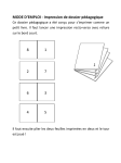
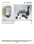
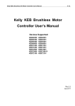
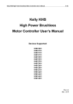
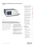
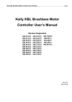
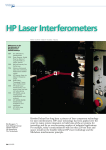
Service
Bulletin
FILING INSTRUCTIONS
Binder: Ag Equipment Binder
Page:
Group / Sub Group: 21 134
Document No.: 0209-T3
Issued By: Technical Services
Supersedes:
Date Issued:
1 of 9
February 18, 2009
MODELS AFFECTED: TL70A, TL80A, TL90A, TL100A Tractors
SUBJECT: Improved Powershuttle PWM Solenoid Valve and
Transmission Software
DESCRIPTION OF CONCERN
An improved Powershuttle PWM solenoid valve and new 24 x 24 transmission controller software have been
developed specifically for service concerns:
•
The new Tecnord™ PWM solenoid valves (part number 84148281), available only through Service Parts,
replace the previous Tecnord PWM solenoid valves (part number 87687115), Figure 1, which were installed
in production.
20091035
1
•
New 24 x 24 transmission controller Software Version 53.02.00.00 has been developed for Tractors
equipped with the Tecnord PWM solenoid valves.
©2009 CNH America LLC. All rights reserved.
Document No.: 0209-T3
•
Subject: Improved Powershuttle PWM Solenoid Valve and Transmission
Software
Page: 2 of 9
New 24 x 24 transmission controller software version 03.02.00.00 has been developed for Tractors equipped
with the previous, Parker™ PWM solenoid valves (part number 5168054), Figure 2, which were installed in
production prior to the introduction of the Tecnord PWM solenoid valves.
20091036
•
•
2
The new transmission software versions can be downloaded through ASIST, and into applicable Tractors,
using the Electronic Service Tool (EST).
New Quick Fill setting values are introduced for the Tecnord PWM solenoid valves with the new transmission
software.
ACTION/CORRECTION
The new Tecnord PWM solenoid valves (part number 84148281), the transmission software applications, and
the additional improvements are detailed in this bulletin.
The new Tecnord PWM solenoid valves are available only through Service Parts, are intended for service use
only, and include these improvements:
•
•
Internal valve components are improved to avoid harsh shuttling at initial start-up when cold, or when
operating for long periods of time in one direction and then changing to the other direction.
A gauze filter, 1, Figure 3, that covers the pressure port is installed to prevent contamination of the valve.
1
2
20091037
3
NOTE: Some later versions of previous Tecnord PWM valve (part number 87687115) were equipped with the
gauze filter. However, these valves will not have the slot, 2, Figure 3, in the bolt head, which the new Tecnord
valves have.
Document No.: 0209-T3
Subject: Improved Powershuttle PWM Solenoid Valve and Transmission
Software
Page: 3 of 9
The new Software Versions 03.02.00.00 and 53.02.00.00 are for service use only, and include these
improvements:
•
•
Improved modulation, quality, and consistency of the shuttle change of direction.
Improved modulation of power clutch engagement.
NOTE: Software Versions 03.02.00.00 and 53.02.00.00 can be used on both previous and new PWM solenoid
valves.
NOTE: These new transmission software versions will be included in EST Software Version 5.3.0.0, which is due
to be released in the near future.
Production:
The Tecnord PWM solenoid valves (part number 87687115) were introduced into production at serial number
HJT075431.
Service:
NOTE: Refer to the Service Manual, Section 55, for the procedures that follow.
If shuttle changes are harsh or clutch engagement is severe, perform the applicable procedure that follows:
IMPORTANT: All PWM solenoid valves fitted on a tractor must be of the same type. Using both Parker and
Tecnord PWM solenoid valves on the same machine is not acceptable. Using both the previous and the new
Tecnord PWM solenoid valves on the same machine is not recommended.
Tractors Equipped with Parker PWM Solenoid Valves:
1. Verify and ensure that all PWM solenoid valves that are installed on the Tractor are Parker valves.
NOTE: The Parker PWM solenoid valve can be identified by its round solenoid coil. See Figure 2.
2. Download Software Version 03.02.00.00 for the Parker PWM solenoid valves as follows:
a. In ASIST, use the Symptom Search Words ‘Harsh Shifting’.
b. Select the Knowledge Resolution ‘Improved Powershuttle PWM Solenoid Valves and Transmission
Software Available’.
c. Select file name: ‘Tier 2 Software’.
d. Follow the instructions to extract the file to the desktop of the EST computer.
e. Open the attached zip file and extract the ‘.hx1’ file to the desktop of the EST computer.
f. Copy the ‘.hx1’ file to EST folder. ‘C:\PCST\Files\Program\TractorAPL2\PA’.
g. Download file ‘PA_03_02_00_00_PARKER.HX1’ to the PA controller.
NOTE: The Quick Fill values for the Parker valves remain unchanged.
3. Calibrate the Powershuttle clutches. See ‘Revised Transmission Calibration Procedure’ in the Additional
Information section of this bulletin for instructions.
IMPORTANT: If the transmission controller is to be replaced with a new controller from Service Parts, the
controller will be loaded with Software Version 03.01.00.00. Software Version 03.02.00.00 MUST be installed
using the EST.
Document No.: 0209-T3
Subject: Improved Powershuttle PWM Solenoid Valve and Transmission
Software
Page: 4 of 9
Tractors Equipped with Tecnord PWM Solenoid Valves:
1. Verify and ensure that all PWM solenoid valves installed on the Tractor are Tecnord valves.
NOTE: The Tecnord PWM solenoid valve can be identified by its square solenoid coil. See Figure 1.
2. Use the PWM solenoid valve kit (part number 9972350), which consists of four new Tecnord PWM solenoid
valves (part number 84148281), to replace the four PWM solenoid valves.
3. Download Software Version 53.02.00.00 for the Tecnord PWM solenoid valves as follows:
a. In ASIST, use the Symptom Search Words ‘Harsh Shifting’.
b. Select the Knowledge Resolution ‘Improved Powershuttle PWM Solenoid Valves and Transmission
Software Available’.
c. Select file name: ‘Tier 2 Software’.
d. Follow the instructions to extract the file to the desktop of the EST computer.
e. Open the attached zip file and extract the ‘.hx1’ file to the desktop of the EST computer.
f. Copy the ‘hx1’ file to EST folder. ‘C:\PCST\Files\Program\TractorAPL2\PA’.
g. Download file ‘PA_53_02_00_00_TECNORD.HX1’ to the PA controller.
4. Adjust the Quick Fill values for the new Tecnord PWM solenoid valves as follows:
a. Park the Tractor on a hard, flat, level surface, and apply the parking brake.
b. Use the service switch to enter the configuration mode.
c. Use the ‘h’ or the ‘m’ button on the instrument cluster to navigate the H-tree:
Use the dim switch on the instrument cluster to select product code ‘PA’, menu ‘H3’, and sub system
‘transmission’. See Figure 4.
20091038
4
NOTE: Product code ‘PA’, mode ‘H3’, and transmission options ‘ch_ _’ will display on the LCD monitor.
d. Use the ‘h’ or the ‘m’ button on the instrument cluster to select ‘Ch_2 - Quick Fill Clutch A’.
NOTE: After a brief timeout, the Quick Fill number will appear.
Document No.: 0209-T3
Subject: Improved Powershuttle PWM Solenoid Valve and Transmission
Software
Page: 5 of 9
e. Use the ‘h’ or the ‘m’ button to set the Quick Fill as specified in the table that follows:
Clutch
Value
Ch 2 - Quick Fill Clutch A
A 40
Ch 3 - Quick Fill Clutch B
B 40
Ch 4 - Quick Fill Clutch C
C 40*
Ch 5 - Quick Fill Clutch D
D 40*
* New values
f. Press the return key (dimming button) on the instrument cluster to store the setting.
g. Repeat Steps 4.d, 4.e and 4.f for the remaining channels.
5. Calibrate the Powershuttle clutches. See ‘Revised Transmission Calibration Procedure’ in the Additional
Information section of this bulletin for instructions.
NOTE: If the transmission controller is to be replaced with a new controller from Service Parts, the controller will
be loaded with Software Version 03.01.00.00. Software Version 53.02.00.00 MUST be installed using the EST.
ADDITIONAL INFORMATION
Revised Transmission Calibration Procedure:
A. Introduction
These procedures should be followed to perform an optimal transmission calibration.
These procedures contain all the external conditions that can have an influence on the transmission calibration.
The calibration procedure must be used when the following has occurred:
•
•
•
•
A new transmission control module has been installed.
The previous calibration has been erased using the ‘H8’ procedure.
A new PWM solenoid valve has been installed.
Transmission performance is reduced, or in the event the harsh shuttling or shifting.
The table that follows lists the calibration that can be performed using ‘H1’, and the module that must be selected.
Calibration
Transmission (24*24)
Module Selection
PA
‘H’ Menu
H1
B. Transmission Calibration
These procedures calibrate all clutches, and determines the current required to achieve the bite point of the
clutches.
Document No.: 0209-T3
Subject: Improved Powershuttle PWM Solenoid Valve and Transmission
Software
Page: 6 of 9
C. Preliminary Conditions for Optimal Calibration (Revised Procedure)
Prior to performing a clutch calibration, it is highly recommended to perform the procedure that follows:
1.
Ensure that the transmission oil is at the correct temperature for calibration, between 70 °C and 90 °C.
NOTE: The transmission oil temperature can be checked in the ‘H1’ menu.
2.
Exit the ‘H1’ menu and turn the ignition switch to the ‘OFF’ position.
3.
Start the engine and perform at least six shuttle maneuvers (‘Forward’ and ‘Reverse’) and at least six
Dual Command shift maneuvers (‘Hi’ and ‘Lo’), engaging each clutch at least three times.
NOTE: Step 3 ensures that the hydraulic circuit and all clutches are at the optimal operating condition prior to
calibration.
D. Clutch Calibration Procedure
NOTE: Transmission output rpm, clutch pedal position, shuttle lever position, and gear/range lever position are
constantly being monitored by the controller being monitored by the controller during the calibration process.
NOTE: The calibration cannot proceed unless the tractor is stationary, the shuttle lever is in gear, the gear lever
is NOT in a neutral position, high 3 rd range is selected, and the clutch pedal is up. If, during the calibration, an
anomalous condition is detected, this will be shown on the display with the relevant error code on the alarm lamp.
Where the abnormality is relative to the calibration, the relevant U error code will be displayed on the LCD.
1.
Park the Tractor on a hard, flat, level surface, and apply the parking brake.
NOTE: The tractor can move during this procedure; ensure that the area around the tractor is clear.
2.
Turn off the air conditioning system and all electrical functions (lights, wipers, radio, etc.), and ensure
that all hydraulic remote control valves are in neutral position.
NOTE: Do NOT turn the steering wheel during the calibration.
3.
If a two-digit number, preceded by the letter ‘U’ is displayed at any time during the calibration procedure,
a standard error has occurred. Correct the fault condition before performing the calibration:
Error Code
U19
U20
U21
U22
U23
U24
U25
U26
U31
U33
U34
U36
U37
Description
Oil Below 10 °C, calibration not allowed.
Incorrect sequence, cycle shuttle lever and clutch pedal.
ERPM too low (<= 1200 rpm).
ERPM too high (>= 1400 rpm).
Shuttle gear in neutral.
Incorrect range selected.
Gear selected in neutral.
Clutch pedal depressed.
Tractor moving.
Park brake not applied.
Seat switch not pressed.
Calibration current too high.
Calibration current too low.
NOTE: When the transmission oil temperature is cold or hot, the clutches CAN be calibrated. However, the
operator will be alerted with one of these warnings:
CL_____ (Cold Oil Warning): Oil temperature is below 20 °C.
CH_____ (Hot Oil Warning): Oil temperature is above 100 °C.
Document No.: 0209-T3
4.
Subject: Improved Powershuttle PWM Solenoid Valve and Transmission
Software
Page: 7 of 9
Use the service switch or the ‘short cut’ while starting the engine to enter the calibration mode:
Service Switch:
1. Use the ‘h’ or the ‘m’ button on the instrument cluster to navigate the H-tree.
2. Use the dim switch on the instrument cluster to select product code ‘PA’, menu ‘H3’, and sub system
‘transmission’. See Figure 5.
20091039
5
Short Cut:
Press and hold both the ‘HI’ and the ‘LO’ switches while starting the engine.
5.
Allow ‘CAL’, Figure 6, to be displayed for a few seconds on the lower central LCD on the instrument
cluster.
20091040
6
NOTE: After two seconds, the oil temperature (in degrees Celsius) will be displayed.
6.
Select ‘3rd’ range’ (fast) and ‘1st’ gear.
7.
Use the hand throttle to adjust the engine speed to 1200 to 1400 rpm.
NOTE: The engine speed must be stable, with no noticeable hunting or surging. If necessary, change the throttle
setting slightly to achieve a stable engine speed.
Document No.: 0209-T3
Subject: Improved Powershuttle PWM Solenoid Valve and Transmission
Software
8.
Check and ensure that the parking brake is applied, and release the clutch pedal.
9.
Place the shuttle lever in ‘Forward’ or ‘Reverse’ (not ‘Neutral’).
Page: 8 of 9
NOTE: The calibration is allowed only if the Operator’s seat is occupied and / or the seat presence switch is
activated.
10. Press and release either the ‘Upshift’ or the ‘Downshift’ switch button.
NOTE: The letter of the clutch under calibration (‘A___’) will be displayed.
11. With the clutch letter on the display, press and hold the ‘Downshift’ switch button.
NOTE: The letter of the clutch under calibration will remain on the display, while the least significant bit (LSB)
digit will display a dash while the auxiliary clutches are applied. Example: ‘A___-’.
12. Allow the calibration process to start.
NOTE: The three LSB digits will display the current value, in milliamps, as it rises during the calibration process.
Example: ‘A123’.
13. When the display stops, and the current value is flashing, make note of the value, as the calibration
current value has been reached.
14. Release the ‘Downshift’ switch button.
NOTE: The next clutch to be calibrated will be displayed. Example: ‘B___’.
15. Repeat Steps 10 through 15 for the remaining clutches (A, B, C and D) to complete the calibration.
16. Turn the ignition switch to the ‘OFF’ position to store the calibrations.
E. Check the Result of the Calibration (Revised Procedure):
Immediately following the initial calibration, repeat the entire Calibration Procedure two more times.
•
•
Carry out the calibration a total of three times, with the transmission oil temperature between 70 °C and
90 °C each time.
If the difference between the lowest value and the highest value obtained for each clutch are within 10
points, the tractor has been successfully calibrated.
Example:
Calibration
1st
2nd
3rd
Value
A256
A258
A256
The difference between the lowest value and the highest value (258 - 256 = 2) is within 10 points.
Document No.: 0209-T3
•
Subject: Improved Powershuttle PWM Solenoid Valve and Transmission
Software
Page: 9 of 9
If the difference between the lowest value and the highest value obtained for each clutch are greater than
10, the tractor must be recalibrated. Repeat the ‘Clutch Calibration Procedure’.
Example:
Calibration
1st
2nd
3rd
Value
A260
A271
A252
The difference between the lowest value and the highest value (271 - 252 = 19) is greater than 10 points.
PARTS AFFECTED
Previous
Part #
NA
NA
Qty
Description
Qty
1
1
New
Part #
9972350
87739361
PAL Ref
Number
1.33.2
1.91.1
NA
NA
5168054
87687115
4
4
Kit, PWM solenoid valve1
Module, Powershuttle
transmission controller2
Valve, PWM solenoid, Parker
Valve, PWM solenoid, Tecnord
NA
4
NA
84148281
1.33.2
1.33.2
1
This part consists of four Tecnord PWM solenoid valves (part number 84148281).
2
This part is equipped with Software Version 03.01.00.00.
WARRANTY STATUS
This service bulletin is for informational purposes
only and does not constitute warranty authorization
to update units without a warrantable failure.