1
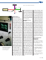
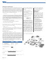
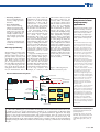
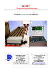
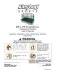
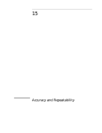
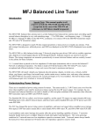
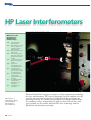
HP Laser Interferometers
P H OTO C O U RT E SY : H E W L E T T PAC K A R D , F I N L A N D .
Milestones in the
develoment of
Displacement
Interferometry:
1887
1902
1960
1964
1966
1968
1970
1972
1973
1975
A.A. Michelson’s
Interferometer
Pieter Zeeman, Nobel
Prize for effects of
magnetic fields on
atomic spectra
Bell Laboratories, first
HeNe laser
Airborne Instruments
Labs, first commercial
displacement interferometer
HP Zeeman laser, stabilized 2 frequency
output
Perkin-Elmer
“Lasergage”, homodyne interferometer
HP 5525A Laser
Interferometer, 2 frequency laser and optical heterodyning
HP 10565A remote
interferometer,
angle/flatness measurement
HP 10690A/10692B
Interferometer,
straightness and
squareness
HP 5501A Laser
Transducer
Rik Kneppers *)
Sales Manager Europe
Hewlett Packard
AR Amstelveen
The Netherlands
34 151/1999
Hewlett Packard has long been a pioneer of laser component technology
for laser interferometry. HP’s laser technology has been applied over the
years by major system integrators to build state-of-the-art systems for
metrology and for an ever-increasing number of industrial applications.
For example, today’s semiconductors with less than 250 nm lines and
spaces would not be feasible without HP’s laser technology and the
Michelson interferometer principle.
Fixed mirror
Figure 1. The basic Michelson interferometer.
Movable mirror
Monochromatic
light source
Beam splitter
(50% reflectance)
Observer
HP has been a
pioneer since 1966
Laser interferometer applications
include some of the world’s most
accurate length and distance
measurement equipment.
Hewlett-Packard (HP) has pioneered laser interferometry
since 1966, in its use of two-frequency lasers based on the
Zeeman principle, and in the
mixing of light beams of two
frequencies (AC or heterodyne
interferometry). The HP interferometer derives its immunity
to air turbulence from a new
two-frequency system described
in detail later in this article.
Until 1966, turbulence had
always been a serious problem
for laser interferometers. The
same heat waves that cause a
distant image on the horizon
to flutter, can also affect the
laser beam. The effect is equivalent to intensity variation.
Similar intensity variations are
produced by absorption and
dispersion from atmospheric
contaminants. One measure of
an interferometer’s ability to
operate under such adverse conditions is the maximum loss of
the returned beam it can tolerate.
Whereas most interferometers remain comfortable with a
50 % loss of signal, the two-frequency interferometer tolerates
more than 95 %. This additional margin of safety also frees
the two-frequency interferometer from periodic electrical
adjustments. There are no adjustments for beam intensity or
trigger threshold. Furthermore,
the interferometer tolerates signal variations produced when
the reflector is rotated.
The inventive work done by
Al Bagley, Len Cutler and Joe
Rando of HP led to the granting
of a patent in 1970.
The use of a laser transducer
made it possible to perform
multi-axis measurements on a
moving stage in X and Y simultaneously. Despite these advantages, there were hardly any
commercial applications for it
when it was introduced in 1975.
Later, the demands for increased accuracy for photo lithography in the semiconductor
industry made the laser transducer a perfect measurement
tool in wafer steppers for close
loop control of the stage in X,
Y and Y’. Today’s semiconductors with less than 250 nm lines
would not be feasible without
laser interferometry.
Laser interferometry
principles
In the basic Michelson interferometer, monochromic light is
directed at a beam splitter (a half
mirror), which passes half the
beam to a movable mirror (the
target), while the remainder is
reflected onto a fixed mirror.
The reflections from the fixed
and movable mirrors are recombined at the beam splitter, where
their interaction is observed.
Each time the movable mirror moves a distance equal to
half the wavelength of the
beam source, the total optical
path of the reflected beams is
changed by a full wavelength,
and the beam reflected from the
moving mirror goes through a
360° phase shift. The shifts cause
alternating re-enforcement and
cancellation of the two reflected beams as they rejoin, producing characteristic fringe patterns, with each cycle of intensity change representing a halfwavelength of mirror travel.
Several improvements have
converted the basic Michelson
interferometer into a practical
electronic measuring instrument. First, a laser light source
permits measurement over long
distances and, because of its high
purity of light (single wavelength), these measurements
are highly accurate.
Second, the mirrors have been
replaced with cube-corner retroreflectors which, unlike flat
mirrors, reflect incident light
parallel to the incoming direction regardless of the angle of
incidence. This property reduces
the need for critical alignment
to generate adequate interference
fringes.
Finally, photocells convert
fringes into voltage pulses,
which are electronically processed to provide both the amount
and direction of position changes.
The low-power helium-neon
laser in the Hewlett-Packard
laser measurement system emits
a coherent light beam composed of two slightly different
optical frequencies, f1 and f2,
of opposite circular polarization (the Zeeman split). After
conversion to orthogonal linear polarization, the beam is
expanded and collimated, then
directed to the reference beam
splitter, where a small fraction
of both frequencies is split off.
This portion of the beam is
used both to generate a reference frequency and to provide
an error signal to the laser-cavity tuning servo. The difference
in the dc levels of f1 and f2 is
used for reference and goes to a
counter in the laser display
unit. The major portion of the
beam passes out of the laser
head to an interferometer. All
Hewlett-Packard interferometers measure the relative displacement of the two reflectors
by splitting the beam into f1
and f2, directing them to two
retroflectors, and returning the
resultant signals to a photodetector.
Laser Interferometer
System error
components
There are many Laser Interferometer System error components, and these can be divided
into three categories:
1. Intrinsic (laser wavelength
accuracy, measurement resolution, optics non-linearity)
2. Environmental (atmospheric
compensation, material
expansion, optical thermal
drift)
3. Installation (deadpath error,
cosine error, abbé error)
In this article, only the atmospheric compensation will be explained in detail.
151/1999 35
Atmospheric Compensation
It is common practice to specify the wavelength of the laser source
as the vacuum wavelength ln. In a vacuum this wavelength is constant, but in any non-vacuum environment it is dependent on the
index-of-refraction of the environment. Since most laser interferometer systems operate in air, it is necessary to correct for the difference between ln and the wavelength in air la. The index-ofrefraction n of the air is related to ln and la by:
n = ln / la
[1]
Changes in air temperature, pressure, composition and humidity
cause changes in the index-of-refraction, thereby changing the needed
correction to the interferometer measurement. Without proper correction or compensation, there will be degradation in system accuracy. For example, assuming standard and homogenous air composition, a one part-per-million error will result from any one of the
following conditions:
– 1 °C (2 °F) change in air temperature
– 2.5 mm (0.1 inch) of mercury change in air pressure
– 80 % change in relative humidity
The wavelength correction or compensation number (WCN) is the
inverse of the index-of-refraction number:
WCN = la / ln
[2]
Since the laser interferometer system counts the number of wavelengths of motion traveled (fringes of light), the actual displacement can be determined as follows:
Actual displacement =
(wavelength counts) * WCN * ln
[3]
This wavelength compensation number can be derived by direct
measurement of the index-of-refraction with a refractometer or by
using empirical data. In the absence of a refractometer, it is best to
measure the air pressure, temperature and relative humidity, and
then to relate this data to the refractive index using the formulas of
Barrel & Sears [2] and Edlen [3]. This method gives only an approximation of the index-of-refraction, and thus has some limitations.
The accuracy of measuring the atmospheric conditions and the formula will determine the magnitude of this error component.
HP calculates the compensation factor to an accuracy of 0.1
ppm by using the following formulas:
T = Air Temperature
P = Air Pressure
H = Relative Humidity
Metric
English
°C
mm Hg
%
°F
inch Hg
%
The use of these formulas suffers from the following disadvantages:
This error term is typically specified in parts-per-million (ppm)
and is a proportional term.
• indirect measurement
• slow response, due to sensor
time constants
• sensors are subject to errors
• sensors require periodic calibration
• ignores air composition
changes in, e.g.
- carbon dioxide
- nitrogen
- chemical vapors
Wide range of
applications
The assumption that the environment measured by the sensors will be the same as in the
interferometer measurement
path, is often not true. Especially
in the nanometer arena the air
composition might not be
homogenous (e.g. air pressure
variations, air turbulence).
The magnitude of the Atmospheric Compensation error
term is dependent on the type
of environment, how much the
environment changes during
an interferometer measurement
and the accuracy of the
method of compensation used.
Figure 3. The X-Y stage layout picture.
6
Compensation Factor
C=
10
6
N + 10
Metric:
é1 + 10 6 * P * (0 .817 - 0.0133 * T )ù
-3
0.057627*T
ú - 3.033 *10 * H * e
N = 0. 3836391 * P * ê
1 + 0. 0036610 *T
ë
û
English:
é 1 + 10 6 * P * (26 . 7 - 0 . 187 * T ) ù
0.032015*T
-3
N = 9 . 74443 * P * ê
ú - 1 . 0899 * 10 * H * e
ë 0 .934915 + 0. 0020388 * T û
36 151/1999
Laser interferometers are used
for high precision measurements of distances from nanometers till 80 m, but also for
measuring angles, flatness,
straightness, squareness, velocity and acceleration (vibrations).
They are mainly used in one of
the following areas:
• Standard laboratories
For measuring the length
standard and calibrating
laser interferometers and
measurement tools.
• Machine Tool calibrations
Calibration of Machine
Tools to check if they can
produce parts within the
required specifications
(microns). Measurements are
performed according to standards like ISO, VDI, BSI,
JIS, ANSI, and NMTBA.
Also needed for ISO9000
machine certification.
quarter wave plate causes the
polarization of the return frequency to be rotated through
90 degrees, so that it will be
reflected out a second time),
one can measure the position
in X and Y, while the stage can
be moved in two dimensions.
The positioning measurement and movement of the
stage can be performed in open
or closed loop control.
Positioning data needs to be
corrected for the atmosphere
(air sensor/wavelength tracker),
mirror flatness, abbé error, data
aging etc. Adding extra interferometers can solve the abbé errors.
For instance, two interferometers on the Y axis (Y and Y’),
separated by a distance D, will
measure the yaw in Y = arctan
((Y-Y’)/D).
Stages are traveling faster and
faster and data aging is becoming a problem. Data aging is
the delay between the time you
take a position on the fly and
the time this data becomes
available. The moment the data
becomes available, it does not
represent the actual positioning
of the stage anymore. For
example, at a velocity of 500
• Measuring machines
For increased (submicron)
accuracy of high precision
machines.
• Servo track writing
Used in the data storage
industry for writing tracks
on each hard disk manufactured, before it can be used
in a PC or workstation, for
example. 10,000 tracks per
inch or higher can be used
today in high capacity hard
disks.
–X-Y stage positioning and
control for the semiconductor industry
X-Y stage positioning
X-Y positioning is used in wafer
steppers, probing, inspection
stations and electron beams to
provide relative accuracy and
repeatability in the nanometer
area. Figure 3 shows an example of a typical X-Y stage layout. The ‘Object Under Control’
is a stage with long plane mirrors on the X and Y sides. By
using plane mirror interferometers (an interferometer with a
mm/s and at 1 micro second of
data aging (caused by the
receivers, cables and electronics), the stage is always off by
500 nm. With constant velocity this is easy to compensate
for, but gets more complex
with accelerations. In practice,
however, data aging is never
constant, but will slightly change
due to changes in signal amplitudes (alignment), frequency
(doppler shifts), temperature
variations, propagation delays
etc. This change is called variable data aging and cannot be
easily compensated for. When
entering the submicron arena,
extreme precaution should be
taken with the environment.
The stage and interferometers
should be inside a conditioned
chamber in which the air temperature and pressure (or turbulence) are tightly controlled (or
■
even in vacuum).
Figure 2. A block diagram of the
HP laser measurement system.
HP Laser Measurement System
Second channel
Reference
beam splitter
Measurement photodetectors
To interferometer
Telescope
2-frequency
HeNe Laser
l/4 and l/2
plates
f1 and f2
Reflected Beam
Demodulating polarizer
Doppler
preamplifier
Mirror
Laser head
Polarizing
beam splitter
Doubler
f1-f2±Df
Forward
counter
SDf Calculator
Photodetectors
Subtractor
Reference
preamplifier
Laser tuning
regulator
f1-f2
Doubler
Forward
counter
and
Dispaly
Display
Unit
Vaisala’s
instruments in laser
interferometry
applications
Vaisala’s barometers, and
relative humidity and temperature transmitters, have
been used for the active
wave-length-of-light compensation of laser interferometer systems with good
results.
Laser interferometer technology
is based on the Michelson principle, invented over a hundred
years ago. The interferometer
principle enables distance measurements to be made at very
high resolution, and accordingly
the most accurate length and
distance measurement equipment in the world relies on laser
interferometer technology.
Applications range from calibration standards for gauge blocks
to semiconductor wafer exposure
systems, to vibration and surface
contour analysis systems.
Vaisala’s barometers and relative humidity and temperature
transmitters are used for the
active wave-length-of-light compensation of laser interferometer
systems. In air, the wavelength of
light changes with the refractive
index of air which, as such, is
affected by the temperature,
absolute pressure and relative
humidity of air.
Vaisala offers various measurement solutions for the environmental control of laser interferometer systems, using measurement
technology that was originally
developed for the most demanding meteorological applications.
The built-in accuracy, stability
and reliability of Vaisala’s instruments can nowadays be applied
to the most demanding industrial
systems, too.
Second channel
References
*) The author, Rik Kneppers joined Hewlett Packard (HP) in 1979 and has dedicated the last 12 years
to working in the area of laser interferometry technology. As a representative of HP Santa Clara
Division (interferometry R&D and manufacturing), he provided submicron application and design
support to the precision mechanical industry and research institutes. Over the years, he has been
actively involved with new interferometer developments to address the increased accuracy and
throughput demands of the semiconductor industry. He is currently working as sales and marketing
manager, heading the HP Precision Motion Control Group in Europe, of which laser interferometry
is a part.
[1] Quenelle, R.C. Nonlinearity in
Interferometer Measurements, HP
Journal April 1983.
[2] Barrell, H. & Sears, J.E., (1939)
Phil Trans. Roy. Society, A258, 1-64
[3] Edlin, B., The Refractive Index
of Air, Metroligia, Vol.2, No.2, 71,
1966
151/1999 37