1
DOWNTOWN 200i
By KWANG YANG Motor Co., Ltd.
1st Edition, Dec 2009
All rights reserved. Any reproduction or
unauthorized use without the written
permission of KWANG YANG Motor Co., Ltd.
is expressly prohibited.
T300-SK40AA-A1
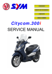
DOWNTOWN 200i
PREFACE
TABLE OF CONTENTS
This Service Manual describes the
technical features and servicing
procedures
for
the
KYMCO
Downtown 200i.
Section 1 contains the precautions for
all operations stated in this manual.
Read them carefully before any
operation is started.
Section 3 describes the inspection/
adjustment procedures, safety rules
and service information for each part,
starting from periodic maintenance.
Most sections start with an assembly
or
system
illustration
and
troubleshooting for the section. The
subsequent pages give detailed
procedures for the section.
KWANG YANG MOTOR CO., LTD.
QUALITY TECHNOLOGY DEPT.
EDUCATION SECTION
ELECTRICAL
EQUIPMENT
The information and contents
included in this manual may be
different from the motorcycle in case
specifications are changed.
CHASSIS
Sections 5 to 12 give instructions for
disassembly,
assembly
and
adjustment of engine parts. Section 13
is the AFI system. Section 14 to 15 is
the removal/ installation of chassis.
Section 16 to 19 states the testing and
measuring methods of electrical
equipment.
1
EXHAUST MUFFLER/FRAME
COVERS
2
INSPECTION/ADJUSTMENT
3
LUBRICATION SYSTEM
4
ENGINE REMOVAL/INSTALLATION 5
ENGINE
Section 2 is the removal/installation
procedures for the frame covers which
are subject to removal/installation
frequency during maintenance and
servicing operations.
GENERAL INFORMATION
CYLINDER HEAD/VALVES
6
CYLINDER/PISTON
7
DRIVE AND DRIVEN PULLEYS/VBELT
8
FINAL REDUCTION
9
A.C. GENERATOR/STARTER
CLUTCH
10
CRANKCASE/CRANKSHAFT
11
COOLING SYSTEM
12
FUEL INJECTION SYSTEM
13
STEERING HANDLEBAR/FRONT
14
WHEEL/FRONT BRAKE/FRONT
SHOCK ABSORBER/FRONT FORK
REAR BRAKE/REAR FORK/REAR 15
WHEEL/REAR SHOCK ABSORBER`
BATTERY/CHARGING SYSTEM
16
IGNITION SYSTEM
17
STARTING SYSTEM
18
LIGHTS SWITCHES / FUEL PUMP
19
1. GENERAL INFORMATION
DOWNTOWN 200i
1
1
________________________________________________________________________________
________________________________________________________________________________
________________________________________________________________________________
________________________________________________________________________________
________________________________________________________________________________
GENERAL INFORMATION
________________________________________________________________________________
SERIAL NUMBER ------------------------------------------------------------------------------------ 1-1
SPECIFICATION ------------------------------------------------------------------------------------- 1-2
SERVICE PRECAUTIONS ------------------------------------------------------------------------- 1-3
TORQUE VALUES ----------------------------------------------------------------------------------- 1-4
SPECIAL TOOLS ------------------------------------------------------------------------------------- 1-6
LUBRICATION POINTS ---------------------------------------------------------------------------- 1-7
CABLE & HARNESS ROUTING--------------------------------------------------------------------- 1-8
1-0
1. GENERAL INFORMATION
DOWNTOWN 200i
SERIAL NUMBER
Location of Frame Serial Number
(inside luggage box)
Location of Vehicle Identification
Number (VIN)
1-1
Location of Engine Serial Number
1. GENERAL INFORMATION
DOWNTOWN 200i
SPECIFICATIONS
Oil filter type
Full-flow filtration
Oil capacity
1.5ℓ
Exchanging capacity
1.3 ℓ
Fi injection system
Air cleaner type & No
Fuel capacity
Paper element, wet
12.5 ℓ
Brand
Throttle Body
Venturi diameter (mm)
Keihin(LGF9)
Butterfly type
32
3 bar
Fuel pump pressure
Electrical system
Reduction gear type
1st
2nd
Auto centrifugal
Two-stage reduction
0.81 ~ 2.57
9.54
Moving device
Tire type
Front wheel
Rear wheel
Front wheel
Rear wheel
Wheel material
Front wheel
Rear wheel
Total
Front wheel
ECU
Ignition type
Ignition timing
4°~32°
Spark plug
CR7E (NGK)
Spark plug gap
0.6~0.7mm
Battery Capacity
12V10AH
Transmission system
Clutch type
Dry multi-disc
Transmission type
CVT
Operation type
Name
Model No.
Overall length
Overall width
Overall height
Wheel base
Engine type
Displacement
Fuel Used
Tubeless
120/80-14 58S
150/70-13 64S
2.0
2.25
Aluminium
Left
40°
Right
Front
40°
Disk brake
Rear
Drum brake
Rear wheel
Total
Ground clearance (mm)
Braking distance (m)
Min. turning radius (m)
Downtown 200i
SK40AA
2200 mm
800 mm
1410 mm
1545 mm
4 stroke O.H.C.
205 cc
92# nonleaded
gasoline
70
104
174
149
205
354
140
7.9m / 30 km/hr
2.6
Engine part
Starting system
Type
Cylinder arrangement
Combustion chamber type
Valve arrangement
Bore x stroke (mm)
Compression ratio
Compression pressure
(kg/cm²)
Max. output (ps/rpm)Engine
Max. torque (kg-m/rpm)
Open
Close
Open
Close
Intake
Damping Device
Front
Telescope
Rear
Swing arm
Shock absorber
Front
110 mm
Idle speed (rpm)
Cooling Type
stroke
Rear
100 mm
Lubrication type
Exhaust
Oil pump type
Starting motor
Gasoline 4-cycle
Single cylinder
Semi-sphere
O.H.C.-4V
φ66 * 60
10.5:1
16
20.6 /8000
2.03 / 6500
5° BTDC
32° BTDC
34° BTDC
5° BTDC
0.10
0.10
1600±100 rpm
Liquid cooling
Forced pressure &
wet sump
Inner/outer rotor
1-2
1. GENERAL INFORMATION
Symbols:
The following symbols represent the
servicing methods and cautions included in
this service manual.
Engine Oil
Grease
Gear Oil
Special
*
: Apply engine oil to the
specified
points.
(Use
designated engine oil for
lubrication.)
: Apply grease for lubrication.
: Transmission Gear Oil (90#)
: Use special tool.
: Caution
: Warning
1-3
DOWNTOWN 200i
1. GENERAL INFORMATION
DOWNTOWN 200i
TORQUE VALUES
1-4
1. GENERAL INFORMATION
TORQUE VALUES
FRAME
1-5
DOWNTOWN 200i
1. GENERAL INFORMATION
Downtown 200i
SPECIAL TOOLS
Tool Name
Tool No.
Performance
Flywheel Puller
A120E00003
A.C. generator flywheel removal
Tappet Adjuster
A120E00012
Tappet adjustment
Oil Seal & Bearing
Installer
A120E00014
Oil seal & bearing installing
Flywheel Holder
A120E00021
A.C. generator flywheel holding
#41 Nut & Fitting
A120E00028
Clutch disassembly & assembly
Thread Protector
A120E00029
Protecting the crankshaft’s
thread
Valve Cotter Installer
A120E00051
Valve cotter installation
Clutch Spring
Compressor
A120E00053
Clutch disassembly & assembly
Shaft Collar Puller
A120E00088
Bearing crankcase removal
Shaft Collar Driver
A120E00091
Bearing crankcase removal
Shaft Collar Installer
A120E00092
Bearing crankcase installation
Bearing Puller
A120E00093
Bearing removal
Lock Nut Socket Wrench
A120F00002
Steering stem removal or
installation
Electric Repair Kit
A120F00032
Fuel injection system diagnosis
Photo
1-6
1. GENERAL INFORMATION
DOWNTOWN 200i
LUBRICATION POINTS
FRAME
The following is the lubrication points for the frame.
Use grease for parts not listed.
Apply engine oil or grease to cables and movable parts not specified. It will avoid abnormal noise
and damage the durability of the motorcycle.
Grease
Grease
Grease
Front wheel axle &nut
1-7
Side stand pivot
& Main stand pivot
Rear wheel axle &nut
1. GENERAL INFORMATION
DOWNTOWN 200i
CABLE & HARNESS ROUTING
Tilt Switch
Speedometer
Radiator Filler Cap
Lo Beam Relay
Ignition Switch
ECU
Hi Beam Relay
Winker Relay
Horn
1-8
1. GENERAL INFORMATION
ISC
Throttle Body
MAP Sensor
1-9
DOWNTOWN 200i
TPS
Injector
WTS
1. GENERAL INFORMATION
DOWNTOWN 200i
Ignition Coil
Fuel Pump Relay
Oil controller
Output Voltage Connector
Coolant Reserve Tank
1-10
1. GENERAL INFORMATION
Starter Relay
DOWNTOWN 200i
Regulator/Rectifier
CPS
1-11
O2 Sensor
2. EXHAUST MUFFLER/FRAME COVERS
DOWNTOWN 200i
2
__________________________________________________________________________________
2
__________________________________________________________________________________
__________________________________________________________________________________
__________________________________________________________________________________
__________________________________________________________________________________
EXHAUST MUFFLER/FRAME COVERS
__________________________________________________________________________________
SERVICE INFORMATION------------------------------------------------ 2- 1
TROUBLESHOOTING----------------------------------------------------- 2- 1
FASTENER REMOVAL AND REINSTALLATION------------------ 2- 2
FRAME COVERS REMOVAL/INSTALLATION --------------------- 2- 3
EXHAUST MUFFLER ----------------------------------------------------- 2-14
2-0
2. EXHAUST MUFFLER/FRAME COVERS
DOWNTOWN 200i
SERVICE INFORMATION
GENERAL INSTRUCTIONS
• When removing frame covers, use care not to pull them by force because the cover joint claws
may be damaged.
• Make sure to route cables and harnesses according to the Cable & Harness Routing.
TORQUE VALUES
Exhaust muffler pipe nuts
Exhaust muffler brake /RR Frok
RR fork/Engine case
TROUBLESHOOTING
Noisy exhaust muffler
• Damaged exhaust muffler
• Exhaust muffler joint air leaks
Lack of power
• Caved exhaust muffler
• Clogged exhaust muffler
• Exhaust muffler air leaks
2-1
1.8~2.2 kgf-m
3.2~3.8 kgf-m
3.0~4.0 kgf-m
2. EXHAUST MUFFLER/FRAME COVERS
DOWNTOWN 200i
FASTENER REMOVAL AND
REINSTALLATION
REMOVAL
Depress the head of fastener center piece {.
Pull out the fastener.
INSTALLATION
Let the center piece stick out toward the head
so that the pawls | close.
Insert the fastener into the installation hole.
* To prevent the pawl | from damage,
insert the fastener all the way into the
installation hole
Push in the head of center piece until it
becomes flush with the fastener outside face.
2-2
2. EXHAUST MUFFLER/FRAME COVERS
DOWNTOWN 200i
FRAME COVERS REMOVAL/
INSTALLATION
SEAT
Unlock the seat with the ignition key.
Open the seat.
Remove the two nuts and the seat.
Installation is in the reverse order of removal.
LUGGAGE BOX
Unlock the seat with the ignition key.
Open the seat.
Remove four bolts, and the fastener on the
right side of luggage box, then lift luggage
box.
Luggage Box Light Connector
Disconnect the luggage box light connector,
then remove the luggage box.
Installation is in the reverse order of removal.
2-3
2. EXHAUST MUFFLER/FRAME COVERS
CENTER COVER
DOWNTOWN 200i
Center Cover
Remove the luggage box.
Remove the center cover.
* During removal, do not pull the joint
claws forcedly to avoid damage.
Installation is in the reverse order of removal.
Remove four bolts and then remove the rear
carrier.
2-4
2. EXHAUST MUFFLER/FRAME COVERS
Installation is in the reverse order of removal.
UPPER/LOWER HANDLEBAR COVER
Remove the four screws and then remove
upper handlebar cover.
Remove the four screws, then remove the
bottom handlebar cover.
Disconnect the throttle cable refer to the
“THROTTLE BODY /TPS” section, then
pull the throttle cable out from the lower
cover. Remove the lower cover.
Installation is in the reverse order of removal.
2-5
DOWNTOWN 200i
2. EXHAUST MUFFLER/FRAME COVERS
DOWNTOWN 200i
WINDSHIELD/WINDSHIELD GARNISH
Remove five bolts and windshield garnish.
2-6
2. EXHAUST MUFFLER/FRAME COVERS
FRONT CENTER COVER
Remove the windshield
Remove four screws, then remove the front
center cover.
Remove the front cover.
Installation is in the reverse order of removal.
FRONT COVER
Remove the small front cover(black) screw
Remove the small front cover(black)
Remove two nuts.
Remove eight screws from the inner cover.
Remove the front cover
2-7
DOWNTOWN 200i
2. EXHAUST MUFFLER/FRAME COVERS
DOWNTOWN 200i
Disconnect the headlight/position light
connector and right/left turn signal light
connectors.
Installation is in the reverse order of removal.
FRONT FENDER
Remove four screws attaching to the front
fender.
Installation is in the reverse order of removal.
RIGHT/LEFT FOOT SKIRT
Remove the six screws attaching to the right
or left skirt.
* During
removal, do not pull the joint
claws forcedly to avoid damage.
Installation is in the reverse order of removal.
2-8
2. EXHAUST MUFFLER/FRAME COVERS
DOWNTOWN 200i
FRONT LOWER COVER
Remove the front cover
Remove the foot skirt
Remove seven screws and front lower cover.
Installation is in the reverse order of removal.
REAR FENDER
Remove the body cover and then the rear
fender.
Installation is in the reverse order of removal.
BODY COVER
Remove the rear center cover.
Remove the right and left foot skirts
Remove the rear carrier.
Remove six screws and two nuts, then
remove the body cover.
2-9
Disconnect the taillight connector.
2. EXHAUST MUFFLER/FRAME COVERS
DOWNTOWN 200i
Taillight Connector
TIRE FENDER
Remove the body cover.
Remove four bolts attaching to the tire fender
Installation is in the reverse order of removal.
FLOORBOARD
Remove the body cover
Remove the right /left skirt
Remove two screws.
2-10
2. EXHAUST MUFFLER/FRAME COVERS
Remove eight
floorboard.
bolts,
UNDER COVER
Remove four bolts
Remove the under cover.
2-11
then
remove
the
DOWNTOWN 200i
2. EXHAUST MUFFLER/FRAME COVERS
DOWNTOWN 200i
Remove the fuel tank cap cover.
Installation is in the reverse order of removal.
Speedometer Wires
METER PANEL
Disconnect the speedometer wires.
Disconnect the DC power connectors.
DC power Connectors
Remove one screws
Remove the ignition key garnish
Remove three screws from the inner cover,
then remove the handler panel.
Installation is in the reverse order of removal.
2-12
2. EXHAUST MUFFLER/FRAME COVERS
DOWNTOWN 200i
INNER COVER
Remove the front cover.
Remove the front lower cover.
Remove the floorboard
(1)
Remove four bolts and front glove box one
screw.
Remove two fastener bolts, then remove
the fuel tank fill cap.
Remove the inner cover
(3)
(5)
(4)
(6)
2-13
(2)
(2)
2. EXHAUST MUFFLER/FRAME COVERS
DOWNTOWN 200i
EXHAUST MUFFLER
REMOVAL
Disconnect the connector with O2 heater/O2
sensor.
Nuts
Remove the two exhaust pipe joint nuts
Remove three muffler mount bolts and
muffler and gasket.
2-14
2. EXHAUST MUFFLER/FRAME COVERS
INSTALLATION
Replace the gasket with a new one.
Install the exhaust muffler and three
mounting bolt.
Install and tighten the two exhaust pipe joint
nuts to the specified torque
Torque: 20 N•m (2 kgf•m,)
Tighten the three mounting bolts
Torque: 35 N•m (3.5 kgf•m,)
Remove the coolant tank cover.
2-15
Gasket
DOWNTOWN 200i
3. INSPECTION/ADJUSTMENT
DOWNTOWN 200i
3
________________________________________________________________________________
________________________________________________________________________________
3
________________________________________________________________________________
________________________________________________________________________________
INSPECTION / ADJUSTMENT
_________________________________________________________________________________________
SERVICE INFORMATION ----------------------------------------------------------------------- 3MAINTENANCE SCHEDULE ------------------------------------------------------------------- 3THROTTLE OPERATION ------------------------------------------------------------------------ 3ENGINE OIL----------------------------------------------------------------------------------------- 3RESERVE TANK ----------------------------------------------------------------------------------- 3AIR CLEANER-------------------------------------------------------------------------------------- 3SPARK PLUG --------------------------------------------------------------------------------------- 3VALVE CLEARANCE----------------------------------------------------------------------------- 3CYLINDER COMPRESSION--------------------------------------------------------------------- 3FINAL REDUCTION GEAR OIL ---------------------------------------------------------------- 3DRIVE BELT ---------------------------------------------------------------------------------------- 3BRAKE SYSTEM----------------------------------------------------------------------------------- 3CLUTCH SHOE WEAR --------------------------------------------------------------------------- 3SUSPENSION --------------------------------------------------------------------------------------- 3NUTS/BOLTS/FASTENERS---------------------------------------------------------------------- 3WHEELS/TIRES ------------------------------------------------------------------------------------ 3STEERING HANDLEBAR------------------------------------------------------------------------ 3SIDE STAND ---------------------------------------------------------------------------------------- 3-
1
2
3
4
5
6
6
7
7
8
8
9
10
10
11
11
11
12
3-0
3. INSPECTION/ADJUSTMENT
DOWNTOWN 200i
SERVICE INFORMATION
GENERAL
! WARNING
• Before running the engine, make sure that the working area is well ventilated. Never run the engine in a
closed area. The exhaust contains poisonous carbon monoxide gas, which may cause death to people.
• Gasoline is extremely flammable and is explosive under some conditions. The working area must be
well ventilated and do not smoke or allow flames or sparks near the working area or fuel storage area.
SPECIFICATIONS
ENGINE
Throttle grip free play
Spark plug
Spark plug gap
Valve clearance
Idle speed
: 2~6 mm
: NGK: CR7E
: 0.6 mm ~ 0.7 mm
: IN: 0.10 mm
EX: 0.10 mm
: 1600±100 rpm
Engine oil capacity:
Cylinder compression: 16±2 kg/cm²
At disassembly : 1.5 Liter
At change
: 1.3 Liter
Gear oil capacity
At disassembly
At change
Ignition timing
Coolant type
: ECU
: Water Cooling
:
: 0.23 Liter
: 0.21 Liter
TIRE
1 Rider
2 Riders
Front
2.00 kg/cm²
2.00 kg/cm²
Rear
2.25 kg/cm²
2.25 kg/cm²
TIRE SPECIFICATION
Front : 120/80-14 58S
Rear : 150/70-13 64S
TORQUE VALUES
Front axle nut : 2 kg-m
Rear axle nut : 12 kg-m
SPECIAL TOOL
Tappet Adjuster
3-1
E012
3. INSPECTION/ADJUSTMENT
3-2
3. INSPECTION/ADJUSTMENT
DOWNTOWN 200i
THROTTLE OPERATION
Check the throttle grip for smooth movement.
Measure the throttle grip free play.
Free Play: 2~6 mm
Major adjustment of the throttle grip free play is
made with the adjusting nut at the throttle body
side. Adjust by loosening the lock nut and turning
the adjusting nut.
Adjusting Nut
Minor adjustment is made with the adjusting nut
at the throttle grip side.
Slide the rubber cover(1) out and adjust by
loosening the lock nut(3) and turning the
adjusting nut(2).
3-3
Lock Nut
3. INSPECTION/ADJUSTMENT
DOWNTOWN 200i
ENGINE OIL
OIL LEVEL INSPECTION
Stop the engine and support the scooter upright
on the level ground.
Wait for 2~3 minutes and check the oil level
with the dipstick. Do not screw in the dipstick
when checking the oil level.
OIL CHANGE
Remove the oil drain bolt to drain the engine oil.
Install the aluminum washer and tighten the oil
drain bolt.
Dipstick
Torque: 2.5 kg-m
* • Replace the aluminum washer with a new
one if it is deformed or damaged.
Pour the recommended oil through the oil filler
hole.
OIL CAPACITY
Oil Drain Bolt
Engine oil capacity: 1.5 L
Engine oil exchanging capacity: 1.3 L
Engine Oil Viscosity : SAE 5W50
OIL FILTER SCREEN INSPECTION
Drain the engine oil.
Remove the oil filter screen attaching the leftunder crankcase.
Clean the oil filter screen.
Install the oil filter screen and filter screen cap.
Fill the engine with recommended engine oil.
Oil Filter Screen
OIL FILTER REPLACEMENT
Remove the oil filler cap attaching the right-under
crankcase cover.
Oil Filter Cap
3-4
3. INSPECTION/ADJUSTMENT
DOWNTOWN 200i
The spring will come out when the filter cap is
removed.
Let the engine oil drain out.
Check that the O-ring is in good condition.
Spring
Install a new oil filter.
* Make sure the rubber seal on the oil filter
facing the left crankcase.
RESERVE TANK
COOLANT LEVEL INSPECTION
The reserve tank is under left floorboard .Check the
coolant level through the inspection window(1) at the
left side skirt white the engine is at the normal
operating temperature , with the scooter In an upright
position.
If the coolant level is below the LOWER level
mark(3), remove the left floor mat ,remove the lid
screw(4), the reserve tank lid(5), and then the reserve
tank cap(6) to add coolant mixture until it reaches the
upper level mark
.
* Add coolant to the reserve tank only. Do not
attempt to add coolant by removing the
radiator cap. Coolant in the radiator is under
pressure and is very hot and can cause
serious burns.
3-5
3. INSPECTION/ADJUSTMENT
DOWNTOWN 200i
AIR CLEANER
AIR FILTER REPLACEMENT
Remove the body cover.
Remove seven screws attaching to the air cleaner
cover.
Remove six screws attaching to the filter.
Check the filter and replace it if it is excessively
dirty or damaged.
Air Cleaner Cover
CHANGE INTERVAL
More frequent replacement is required when
riding in unusually dusty or rainy areas.
* • The air cleaner element has a viscous type
paper element. Do not clean it with
compressed air.
• Be sure to install the air cleaner element
and cover securely.
SPARK PLUG
Remove the spark plug cap and spark plug.
Check the spark plug for wear and fouling
deposits.
Clean any fouling deposits with a spark plug
cleaner or a wire brush.
Specified Spark Plug: NGK-CR7E
Measure the spark plug gap.
Spark Plug Gap: 0.6 – 0.7 mm
Spark Plug
* • When installing, first screw in the spark
plug by hand and then tighten it with a
spark plug wrench.
Cracks
Damage
Torque:17.2 N-m
Gap
Wear
Fouling
Deposits
}
Deformation
0.6~0.7 mm
3-6
3. INSPECTION/ADJUSTMENT
DOWNTOWN 200i
Cylinder Head Cover
VALVE CLEARANCE
* • Inspect and adjust valve clearance while
the engine is cold (below 35℃).
Remove the seat assy and luggage box.
Remove the four bolts and then cylinder head
cover.
Turn the A.C. generator flywheel to the top dead
center (TDC) on the compression stroke so that
the “T” mark on the flywheel aligns with the
index mark on the left crankcase cover.
Inspect and adjust valve clearance.
Valve Clearance: IN: 0.10 mm
EX: 0.10 mm
Loosen the lock nut and adjust by turning the
adjusting nut
Special
Valve Adjuster
Feeler Gauge
E012
* • Check the valve clearance again after the
lock nut is tightened.
CYLINDER COMPRESSION
Warm up the engine before compression test.
Remove the center cover and luggage box.
Remove the spark plug.
Insert a compression gauge.
Open the throttle fully and push the starter button
to test the compression.
Max. Compression: 16±2 kg/cm2
If the compression is low, check for the following:
‧Leaky valves
‧Valve clearance too small
‧Leaking cylinder head gasket
‧Worn piston rings
‧Worn piston/cylinder
If the compression is high, it indicates that carbon
deposits have accumulated on the combustion
chamber and the piston head.
3-7
Bolts
Top Dead Center Mark
3. INSPECTION/ADJUSTMENT
DOWNTOWN 200i
FINAL REDUCTION GEAR OIL
* • Place the scooter on its main stand on level
ground.
Remove the transmission fluid drain bolt.
Remove the transmission fluid filler bolt, then
slowly rotate the rear wheel to drain the fluid.
Fill the transmission with the recommend fluid to
the capacity listed below.
Oil Drain Bolt
Transmission fluid type: SAE 90
Transmission fluid capacity: 0.23 L
Transmission fluid exchanging
capacity: 0.21 L
Install the transmission filler bolt and tighten it to
the specified torque.
Oil Filler Bolt
DRIVE BELT
Remove the left crankcase cover.
Inspect the drive belt for cracks or excessive wear.
Replace the drive belt with a new one if necessary
and in accordance with the Maintenance Schedule.
Drive Belt
3-8
3. INSPECTION/ADJUSTMENT
BRAKE SYSTEM
There is adjuster on each brake lever.Each
adjuster has four positions so that the released
lever position can be adjusted to suit the rider’s
hands.
To adjust the distance of the lever from the
handlebar grip,push the lever(1) forward and turn
the adjuster knob(2) to align the number with the
arrow mark(3) on the lever holder.
BRAKE DISK/BRAKE PAD
Check the brake disk surface for scratches,
unevenness or abnormal wear.
Check if the brake disk runout is within the
specified service limit.
Check if the brake pad wear exceeds the wear
indicator line.
* Keep grease or oil off the brake disk to
avoid brake failure.
BRAKE FLUID
Turn the steering handlebar upright and check if
both brake fluid levels is at the upper limit. If the
brake fluid is insufficient, fill to the upper limit.
Specified Brake Fluid: DOT-4
* The brake fluid level will decrease if the
brake pads are worn.
3-9
DOWNTOWN 200i
3. INSPECTION/ADJUSTMENT
DOWNTOWN 200i
CLUTCH SHOE WEAR
Start engine and check the clutch operation by
increasing the engine speed gradually.
If the motorcycle tends to creep or the engine stop,
check the clutch shoes for wear and replace if
necessary.
SUSPENSION
FRONT
Check the action of the front shock absorbers by
compressing them several times.
Check the entire shock absorber assembly for oil
leaks, looseness or damage.
REAR
Each shock absorber(4) on your scooter has 5
spring preload adjustment positions for different
load or riding conditions.
Use a pin spanner(5) to adjust the rear shock
spring preload. Position 1 is for light loads and
smooth road conditions. Position 3 to 5 increase
spring preload for a stiffer rear suspension and
can be used when the scooter is heavily loaded.
Be certain to adjust both shock absorbers to the
same spring preload positions.
3-10
3. INSPECTION/ADJUSTMENT
DOWNTOWN 200i
NUTS/BOLTS/FASTENERS
Check all important chassis nuts and bolts for
looseness.
Tighten them to their specified torque values if
any looseness is found.
WHEELS/TIRES
Check the tires for cuts, imbedded nails or other
damages.
Check the tire pressure.
* • Tire pressure should be checked when tires
are cold.
Tire Pressure
1 Rider
1 Rider (with
passenger)
Front
2.00 kg/cm²
2.00 kg/cm²
Rear
2.25 kg/cm²
2.25 kg/cm²
Tire Size:
Front
Rear
120/80-14
150/70-13
Front Axle Nut
58S
64S
Check the front axle nut for looseness.
Check the rear axle nut for looseness.
If the axle nuts are loose, tighten them to the
specified torques.
Torque:
Front axle nut
Rear axle nut
2 kg-m
12 kg-m
Rear Axle Nut
STEERING HANDLEBAR
Raise the front wheel off the ground and check
that the steering handlebar rotates freely.
If the handlebar moves unevenly, binds, or has
vertical movement, adjust the steering head
bearing.
3-11
3. INSPECTION/ADJUSTMENT
DOWNTOWN 200i
SIDE STAND
Your scooter's side stand is not only necessary when
you park, but it contains an important safety feature.
This feature cuts-off the ignition if you try to ride the
scooter when the side stand is down. Perform the
following side stand inspection.
INTERLOCK FUNCTION CHECK
Check the side stand ignition cut-off system,
1. Place the scooter on its center stand.
2. Put the side stand up and start the engine.
3. Lower the side stand. The engine should stop as
you put the side stand down.
*
If the side stand system does not operate as
described, see your KYMCO dealer for
service.
3-12
4. LUBRICATION SYSTEM
DOWNTOWN 200i
4
________________________________________________________________________________
________________________________________________________________________________
4
________________________________________________________________________________
________________________________________________________________________________
________________________________________________________________________________
LUBRICATION SYSTEM
________________________________________________________________________________
LUBRICATION SYSTEM------------------------------------------------------------------------- 4-1
SERVICE INFORMATION ----------------------------------------------------------------------- 4-2
TROUBLESHOOTING ---------------------------------------------------------------------------- 4-2
ENGINE OIL/OIL FILTER------------------------------------------------------------------------ 4-3
OIL PUMP-------------------------------------------------------------------------------------------- 4-5
4-0
4. LUBRICATION SYSTEM
DOWNTOWN 200i
LUBRICATION PART
Dipstick
Oil Filter
Oil Pump
Drive Chain
4-1
4. LUBRICATION SYSTEM
DOWNTOWN 200i
SERVICE INFORMATION
GENERAL INSTRUCTIONS
• The maintenance of lubrication system can be performed with the engine installed on the frame.
• Drain the coolant before starting any operations.
• Carefully when removing and installing the oil pump not to allow dust and foreign matters to enter the
engine and oil line.
• Do not attempt to disassemble the oil pump. The oil pump must be replaced as a set when it reaches its
service limit.
• After the oil pump is installed, check each part for oil leaks.
SPECIFICATIONS
ENGINE OIL
Engine Oil Capacity
Recommended Oil
At disassembly: 1.5 liter
SAE5W50#
At change: 1.3 liter
API: SJ
TROUBLESHOOTING
Oil level too low
• Natural oil consumption
• Oil leaks
• Worn piston rings
• Worn valve guide
• Worn valve guide seal
Poor lubrication pressure
• Oil level too low
• Clogged oil filter or oil passage
• Faulty oil pump
Oil contamination
• Oil not changed often enough
• Faulty cylinder head gasket
• Loose cylinder head bolts
4-2
4. LUBRICATION SYSTEM
DOWNTOWN 200i
Oil Dipstick
ENGINE OIL/OIL FILTER
* • Place the scooter upright on level ground
for engine oil level check.
• Run the engine for 2~3 minutes and check
the oil level after the engine is stopped for
2~3 minutes.
Remove the oil dipstick and check the oil level
with the oil dipstick.
If the level is near the lower level, fill to the upper
level with the recommended engine oil.
OIL CHANGE
* • The engine oil will drain more easily while
the engine is warm.
Remove the oil drain bolt located at the left side
of the engine to drain the engine oil.
After the oil has been completely drained, install
the aluminum washer and tighten the oil drain
bolt.
Torque: 24.5 N-m
Pour the recommended oil through the oil filler
hole.
OIL FILTER SCREEN
Drain the engine oil.
Remove the oil filter screen cap.
Remove the oil filter screen and spring.
Check the oil filter screen for clogging or damage
and replace if necessary. Check the filter screen
O-ring for damage and replace if necessary.
Install the oil filter screen, spring, O-ring and
filter screen cap.
Torque: 12.7N-m
Recommended Oil: SAE5W50# API: SJ
Oil Capacity:
At disassembly: 1.5 liter
At change: 1.3 liter
Start the engine and check for oil leaks. Start
the engine and let it idle for few minutes, then
recheck the oil level.
4-3
4. LUBRICATION SYSTEM
DOWNTOWN 200i
OIL FILTER REPLACEMENT
Remove the oil filler cap attaching the right-under
crankcase cover.
Oil Filter Cap
The spring will come out when the filter cap is
removed.
Let the engine oil drain out.
Check that the O-ring is in good condition.
Spring
Install a new oil filter.
* Make sure the rubber seal on the oil filter
facing the left crankcase
4-4
4. LUBRICATION SYSTEM
DOWNTOWN 200i
OIL PUMP REMOVAL
Remove twelve bolts attaching the right crankcase
cover.
Remove the A.C. generator flywheel with special
tool.
Special tool:
Flywheel Puller
Universal Holder
E003
E021
Starter Idle Gear
Remove the gasket and dowel pins.
Remove the starter idle gear and starter clutch.
Dowel Pin
Remove the two bolts and oil separator cover.
Oil Separator Cover
Remove the oil pump driven gear clip to remove
the oil pump driven gear and drive chain.
4-5
Oil Pump Drive Chain
4. LUBRICATION SYSTEM
DOWNTOWN 200i
Arrow Mark
Remove two oil pump mounting bolts and the oil
pump.
OIL PUMP INSTALLATION
Install the oil pump into the crankcase.
* Install the oil pump with the arrow on the
pump body facing up and fill the oil pump
with engine oil before installation.
Pump Shaft
After the oil pump is installed, tighten the two
mounting bolts.
Install the pump driven gear and drive chain by
aligning the pump driven gear with the cutout in
the pump shaft.
Install and tighten the pump driven gear bolts.
Install the oil separator cover and tighten the bolts.
Oil Separator Cover
Install the starter idle gear and starter clutch.
Install the gasket and dowel pins.
Starter Idle Gear
Install the right crankcase cover and tighten the
twelve bolts.
Torque: 1.2 kg-m
* Diagonally tighten the bolts in 2~3 times.
Dowel Pin
4-6
5. ENGINE REMOVAL/INSTALLATION
DOWNTOWN 200i
5
__________________________________________________________________________________
__________________________________________________________________________________
__________________________________________________________________________________
__________________________________________________________________________________
5
__________________________________________________________________________________
ENGINE REMOVAL/INSTALLATION
__________________________________________________________________________________
SERVICE INFORMATION------------------------------------------------ 5-1
ENGINE REMOVAL/INSTALLATION--------------------------------- 5-2
ENGINE HANGER --------------------------------------------------------- 5-6
5-0
5. ENGINE REMOVAL/INSTALLATION
DOWNTOWN 200i
SERVICE INFORMATION
GENERAL INSTRUCTIONS
• A floor jack or other adjustable support is required to support and maneuver the engine. Be
careful not to damage the scooter body, cables and wires during engine removal.
• Use shop towels to protect the scooter body during engine removal.
• Drain the coolant before removing the engine.
• After the engine is installed, fill the cooling system with coolant and be sure to bleed air from the
water jacket. Start the engine to check for coolant leaks.
• Before removing the engine, the rear brake caliper must be removed first. Be careful not to bend
or twist the brake fluid tube.
SPECIFICATIONS
Engine oil capacity:
At disassembly: 1.5 L
At change: 1.3 L
Coolant capacity:
Radiator:
Hose with cool coolant:
Hose with hot coolant:
Reserve tank:
Total capacity:
870 cc
169 cc
194 cc
490 cc
1360 cc
TORQUE VALUES
90304-GHE8-0040
90305-LBD4-9000
95801-10060
90305-KFW6-9120-M1
95801-10035-00
5-1
Engine hanger (Engine side)
Engine hanger (Frame side)
Rear fork mount bolts
Rear axle nut
Rear cushion lower/upper mount bolts
5.0 kgf-m (50 N-m)
6.5 kgf-m (65 N-m)
3.5 kgf-m (35 N-m)
12.0 kgf-m (120 N-m)
4.0 kgf-m (40 N-m)
5. ENGINE REMOVAL/INSTALLATION
DOWNTOWN 200i
ENGINE
REMOVAL/INSTALLATION
REMOVAL
Remove the air cleaner
Disconnect the connector including of ISC,
Throttle body, TPS, WTS, MAP sensor and
injector.
Disconnect the O2 sensor connector.
Disconnect the throttle cables.
Disconnect
the
Regulator/Rectifier
connector.
Disconnect the starter relay wire from
starter motor.
Remove a bolt from fuel hose guide.
Disconnect the fuel hose from fuel injector.
Fuel hose guide
Disconnect the input water hose.
Disconnect the air bleed hose.
Water hose
Oil filter
Water pump
5-2
5. ENGINE REMOVAL/INSTALLATION
DOWNTOWN 200i
(4)
(3)
Remove the muffler.
Remove the rear fork mounting bolts (1)
attaching to the crankcase.
Torque: 3.5 kgf-m (35 N-m)
Remove the rear axle nut (2).
Torque: 12.0 kgf-m (120 N-m)
Remove two bolts (3) attaching to rear brake
hose clamps.
Remove two bolts (4) attaching to the rear
brake caliper.
Torque: 3.2 kgf-m (32 N-m)
(2)
(1)
Disconnect the alternator connector (5).
Disconnect the ignition pulse generator
connector (6).
(6)
(5)
(7)
Release the rubber cap and remove the
terminal screw (7) to disconnect the start
motor cable from the start motor.
Remove the bolt and engine ground cable.
5-3
5. ENGINE REMOVAL/INSTALLATION
DOWNTOWN 200i
Remove the spark plug cap.
Spark Plug Cap
Disconnect the lower radiator hose from
lower radiator pipe.
Radiator Hose
Remove the right and left rear cushion lower
mount bolts.
Torque: 4.0 kgf-m (40N-m)
Mount Bolt
5-4
5. ENGINE REMOVAL/INSTALLATION
DOWNTOWN 200i
Remove the engine mount nut and pull it out.
Remove the engine from the frame.
* At removing the engine, be careful not
to catch your hand or finger between
the engine hanger and crankcase.
Torque: 6.5 kgf-m (65 N-m)
Mount Nut
INSTALLATION
Installation is in the reverse order of removal.
After installation, inspect and adjust the
following:
• Throttle grip free play
• Fill the cooling system with coolant and
start the engine to bleed air from the system.
API/ABV Reset (Refer to chapter14, page 17)
5-5
5. ENGINE REMOVAL/INSTALLATION
ENGINE HANGER
DOWNTOWN 200i
Mount Nut
REMOVAL
Remove the engine mount nut and pull it out.
* Be careful to put the engine down.
Remove the left/right engine hanger mount
bolt.
Remove the engine from frame.
INSTALLATION
Installation is in the reverse order of removal.
Tighten the engine hanger mount bolts to the
specified torque.
Torque: 6.5 kgf-m (65 N-m)
5-6
6. CYLINDER HEAD/VALVES
DOWNTOWN 200i
6.
________________________________________________________________________________
________________________________________________________________________________
________________________________________________________________________________
________________________________________________________________________________
6
________________________________________________________________________________
CYLINDER HEAD/VALVES
_________________________________________________________________________________________
SCHEMATIC DRAWING ------------------------------------------------------------------------- 6-1
SERVICE INFORMATION ----------------------------------------------------------------------- 6- 2
TROUBLESHOOTING ---------------------------------------------------------------------------- 6- 3
CYLINDER HEAD COVER REMOVAL------------------------------------------------------- 6- 4
CAMSHAFT REMOVAL-------------------------------------------------------------------------- 6- 4
CYLINDER HEAD REMOVAL------------------------------------------------------------------ 6- 6
CYLINDER HEAD DISASSEMBLY------------------------------------------------------------ 6- 7
CYLINDER HEAD ASSEMBLY ---------------------------------------------------------------- 6- 8
CYLINDER HEAD INSTALLATION----------------------------------------------------------- 6- 9
CAMSHAFT INSTALLATION------------------------------------------------------------------- 6- 9
CYLINDER HEAD COVER INSTALLATION------------------------------------------------ 6- 11
6-0
6. CYLINDER HEAD/VALVES
SCHEMATIC DRAWING
6-1
DOWNTOWN 200i
6. CYLINDER HEAD/VALVES
DOWNTOWN 200i
SERVICE INFORMATION
GENERAL INSTRUCTIONS
• The cylinder head can be serviced with the engine installed in the frame. Coolant in the radiator and
water hoses must be drained.
• When assembling, apply molybdenum disulfide grease or engine oil to the valve guide movable parts and
valve arm sliding surfaces for initial lubrication.
• The valve rocker arms are lubricated by engine oil through the engine oil passages. Clean and unclog the
oil passages before assembling the cylinder head.
• After disassembly, clean the removed parts and dry them with compressed air before inspection.
• After removal, mark and arrange the removed parts in order. When assembling, install them in the reverse
order of removal.
Standard (mm)
SPECIFICATIONS
Item
Valve clearance (cold)
IN
EX
Cylinder head compression pressure
Camshaft cam height
Valve rocker arm I.D.
Valve rocker arm shaft
O.D.
Valve seat width
Valve stem O.D.
Valve guide I.D.
Valve stem-to-guide
clearance
0.10
0.10
16 kg/cm²
IN
EX
IN
EX
IN
EX
IN
EX
IN
EX
IN
EX
IN
EX
35.8281
35.8437
12.00~12.018
12.00~12.018
11.966~11.984
11.966~11.984
1.2
1.2
4.990~4.975
4.970~4.955
5.00~5.012
5.00~5.012
0.010~0.037
0.030~0.057
TORQUE VALUES
SPECIAL TOOL
Valve spring compressor
E063
6-2
6. CYLINDER HEAD/VALVES
DOWNTOWN 200i
TROUBLESHOOTING
• The poor cylinder head operation can be diagnosed by a compression test or by tracing engine top-end
noises.
Poor performance at idle speed
• Compression too low
Compression too low
• Incorrect valve clearance adjustment
• Burned or bend valves
• Incorrect valve timing
• Broken valve spring
• Poor valve and seat contact
• Leaking cylinder head gasket
• Warped or cracked cylinder head
• Poorly installed spark plug
Compression too high
• Excessive carbon build-up in combustion
chamber
6-3
White smoke from exhaust muffler
• Worn valve stem or valve guide
• Damaged valve stem oil seal
Abnormal noise
• Incorrect valve clearance adjustment
• Sticking valve or broken valve spring
• Damaged or worn camshaft
• Worn cam chain tensioner
• Worn camshaft and rocker arm
6. CYLINDER HEAD/VALVES
DOWNTOWN 200i
Cylinder Head Cover
CYLINDER HEAD COVER REMOVAL
Remove the met-in box.
Remove the body cover and center cover.
Disconnect the breather hose to air cleaner.
Remove the cylinder head cover four bolts.
Remove the cylinder head cover.
Bolts
CAMSHAFT REMOVAL
Remove the injector and inlet pipe.
Remove two screws attaching the thermostat.
Injector
Thermostat
Inlet pipe
Turn the cam chain tensioner screw clockwise to
tighten it.
Cam chain tensioner
Torque: 1.0 kgf-m (9.8 N-m)
6-4
6. CYLINDER HEAD/VALVES
DOWNTOWN 200i
Nuts
Remove four nuts attaching to the cylinder head.
* • Diagonally loosen the cylinder head cap
nuts in 2 or 3 times.
.
Remove two bolts attaching to the camshaft gear.
Remove the camshaft gear from the cam chain
Bolts
Set Plate
Remove the set plate located beside the rocker
arm shaft.
6-5
6. CYLINDER HEAD/VALVES
DOWNTOWN 200i
Remove the rocker arm with bolt as shown.
Rocker Arm
CAMSHAFT INSPECTION
Check each cam lobe for wear or damage.
Check each camshaft bearing for play or damage.
Replace the camshaft assembly with a new one if
the bearings are noisy or have excessive play.
* If the surface of rocker arm is worn, check
Rocker Arm
each cam lobe for wear or damage.
Camshaft
Bolt
CYLINDER HEAD REMOVAL
Remove the muffler.
Remove the throttle body.
Drain the coolant from the radiator and water
hose, then remove the thermostat water hose.
Remove the camshaft.
Remove the Temp/Map Sensor and intake
manifold.
Remove the bolt attaching the thermostat housing
and the thermostat housing.
Remove the cylinder head.
Thermostat
6-6
6. CYLINDER HEAD/VALVES
Remove two nuts attaching to the upper/lower
side of cylinder head.
Remove two bolts attaching to the cylinder head.
Remove the cylinder head.
Remove the dowel pins and cylinder head gasket.
Remove the cam chain guide.
Remove all gasket material from the cylinder
head mating surface.
* Be careful not to drop any gasket material
into the engine.
DOWNTOWN 200i
Nut
Bolts
Cylinder Head Gasket
CYLINDER HEAD DISASSEMBLY
Remove the valve spring cotters, retainers,
springs, spring seats and valve stem seals using a
valve spring compressor.
* • Be
sure to compress the valve springs
with a valve spring compressor.
• Mark all disassembled parts to ensure
correct reassembly.
Cam Chain Guide
Special
Valve spring compressor
E040
Remove carbon deposits from the exhaust port
and combustion chamber.
Valve Spring Compressor
6-7
Dowel pins
6. CYLINDER HEAD/VALVES
DOWNTOWN 200i
VALVE STEM INSPECTION
Inspect each valve for bending, burning, or
abnormal stem wear.
Intake valve
Remove carbon deposits from the combustion
chamber.
Clean off any gasket remnants from the cylinder
head contact surface.
Exhaust valve
Valves
* Be careful not to damage the cylinder head
mating surface.
CYLINDER HEAD ASSEMBLY
Install the valve spring seats and stem seals.
Lubricate each valve stem with engine oil and
insert the valves into the valve guides.
Be sure to install new valve stem seals.
Install the valve spring.
Special
Valve spring compressor
E040
* • Tap the valve stems gently with a plastic
hammer for 2~3 times to firmly seat the
cotters.
• Be careful not to damage the valves.
Valve spring compressor
6-8
6. CYLINDER HEAD/VALVES
DOWNTOWN 200i
CYLINDER HEAD INSTALLATION
Dowel Pins
Install the dowel pins and a new cylinder head
gasket.
Install the cam chain guide.
* • Clean the intake valve rocker arm shaft
off any grease before installation.
Gasket
Install the cylinder head.
Install the camshaft.
Cam chain guide
Cylinder Head
Nut
Install the intake valve rocker arm and the rocker
arm shafts.
Bolts
CAMSHAFT INSTALLATION
Install the set plate to prevent the rocker arm shaft
from pull out.
Torque: 1.2 kgf-m (8.9 N-m)
6-9
Bolt
Fix plate
6. CYLINDER HEAD/VALVES
DOWNTOWN 200i
Tighten the four cylinder head nuts and the four
bolts between the cylinder head and cylinder.
Nuts
Torque:
Cylinder head nuts: 3.6 kgf-m (35.3 N-m)
Turn the A.C. generator flywheel so that the “T”
mark on the flywheel aligns with the index mark
on the right crankcase cover.
Keep the round hole on the camshaft gear facing
up and align two bolts on the camshaft gear with
the cylinder head surface (Position the intake and
exhaust cam lobes down.) and install the cam
chain over the camshaft gear.
Camshaft Gear
Round hole
* • Apply
engine oil to the threads of the
cylinder head cap nuts.
• Diagonally tighten the cylinder head cap
nuts in 2~3 times.
• First tighten the cylinder head cap nuts and
then tighten the bolts between the cylinder
and cylinder head to avoid cracks.
Bolts
Install the thermostat bolt.
Torque: 1.2 kgf-m (11.8 N-m)
Turn the cam chain tension screw counterclockwise to release it.
6-10
6. CYLINDER HEAD/VALVES
CYLINDER HEAD COVER
INSTALLATION
Adjust the valve clearance.
Install a new cylinder head cover O-ring and
install the cylinder head cover.
DOWNTOWN 200i
Thermostat
Injector
* Be sure to install the O-ring into the groove
properly.
Install the inlet pipe.
Install the injector.
Install and tighten the cylinder head cover bolts.
Inlet pipe
6-11
7. CYLINDER/PISTON
DOWNTOWN 200i
7
________________________________________________________________________________
________________________________________________________________________________
________________________________________________________________________________
________________________________________________________________________________
________________________________________________________________________________
CYLINDER/PISTON
7
_________________________________________________________________________________________
SCHEMATIC DRAWING ------------------------------------------------------------------------- 7-1
SERVICE INFORMATION ----------------------------------------------------------------------- 7-2
TROUBLESHOOTING ---------------------------------------------------------------------------- 7-2
CYLINDER REMOVAL--------------------------------------------------------------------------- 7-3
PISTON REMOVAL ------------------------------------------------------------------------------- 7-3
PISTON INSTALLATION ------------------------------------------------------------------------ 7-7
CYLINDER INSTALLATION-------------------------------------------------------------------- 7-7
7-0
7. CYLINDER/PISTON
SCHEMATIC DRAWING
7-1
DOWNTOWN 200i
7. CYLINDER/PISTON
DOWNTOWN 200i
SERVICE INFORMATION
GENERAL INSTRUCTIONS
• The cylinder and piston can be serviced with the engine installed in the frame.
• When installing the cylinder, use a new cylinder gasket and make sure that the dowel pins are correctly
installed.
• After disassembly, clean the removed parts and dry them with compressed air before inspection.
SPECIFICATIONS
Standard (mm)
Service Limit (mm)
66.0~66.02
66.10 over
top
0.015~0.055
0.09 over
Second
0.015~0.055
0.09 over
top
0.15~0.30
0.50 over
Second
0.30~0.45
0.2~0.7
0.50 over
1.0 over
Piston O.D.(A)
65.98~65.99
65.9belw
Piston O.D.(B)
66.99~66.00
65.9belw
Item
Cylinder
I.D.
Ring-to-groove
clearance
Piston,
Ring end gap
piston ring
Oil side rail
Piston O.D. measuring position
.
Piston-to-cylinder clearance
Piston pin hole I.D.
Piston pin O.D
Piston-to-piston pin clearance
Connecting rod small end I.D. bore
9mm from bottom of skirt
0.010~0.030
0.1 over
17.002~17.008
17.06 over
16.994~17.000
16.80 belw
0.002~0.014
0.02 over
17.016~17.034
17.06 over
TROUBLESHOOTING
• When hard starting or poor performance at low speed occurs, check the crankcase breather for white
smoke. If white smoke is found, it means that the piston rings are worn, stuck or broken.
Compression too low or uneven
compression
• Worn or damaged cylinder and piston rings
• Worn, stuck or broken piston rings
Compression too high
• Excessive carbon build-up in combustion
chamber or on piston head
Excessive smoke from exhaust muffler
• Worn or damaged piston rings
• Worn or damaged cylinder and piston
Abnormal noisy piston
• Worn cylinder, piston and piston rings
• Worn piston pin hole and piston pin
• Incorrectly installed piston
7-2
7. CYLINDER/PISTON
CYLINDER REMOVAL
DOWNTOWN 200i
Cylinder
Dowel Pins
Remove the cylinder head.
Remove the cam chain guide.
Remove the cylinder.
Water Hose
Remove the cylinder gasket and dowel pins.
Clean any gasket material from the cylinder
surface.
Gasket
Cam Chain Guide
Dowel Pins
PISTON REMOVAL
Remove the piston pin clip.
Press the piston pin out of the piston.
* Place a clean towel in the crankcase to
keep the piston pin clip from falling into
the crankcase.
7-3
Piston
Piston Rings
Piston Pin
7. CYLINDER/PISTON
DOWNTOWN 200i
Inspect the piston, piston pin and piston rings.
Remove the piston rings.
* Take care not to damage or break the
piston rings during removal.
Clean carbon deposits from the piston ring
grooves.
Install the piston rings onto the piston and
measure the piston ring-to-groove clearance.
Service Limits:
Top: 0.09 mm replace if over
2nd: 0.09 mm replace if over
Remove the piston rings and insert each
piston ring into the cylinder bottom.
* Use the piston head to push each piston
ring into the cylinder.
Measure the piston ring end gap.
Service Limit: 0.5mm replace if over
Measure the hole I.D. of piston pin
Service Limit: 17.06 mm replace if over
7-4
7. CYLINDER/PISTON
DOWNTOWN 200i
Measure the piston pin O.D.
Service Limit: 16.8 mm replace if below
Measure the piston O.D.
*Take measurement at 9mm from the bottom
and 90° to the piston pin hole.
Service Limit: 65.9mm replace if below
Measure the piston-to-piston pin clearance.
Service Limit: 0.02mm replace if over
CYLINDER INSPECTION
Inspect the cylinder bore for wear or damage.
Measure the cylinder I.D. at three levels of
top, middle and bottom at 90° to the piston
pin (in both X and Y directions).
Service Limit:
66.1 mm repair or replace if over
Measure the cylinder-to-piston clearance.
Service Limit:
0.1 mm repair or replace if over
The true roundness is the difference between
the values measured in X and Y directions.
The cylindricity (difference between the
values measured at the three levels) is subject
to the maximum value calculated.
Service Limits:
True Roundness:
0.05mm repair or replace if over
Cylindricity: 0.05 mm repair or replace if over
Top
Middle
Bottom
7-5
7. CYLINDER/PISTON
DOWNTOWN 200i
Measure the connecting rod small end I.D.
Service Limit: 17.06 mm replace if over
PISTON RING INSTALLATION
Install the piston rings onto the piston.
Apply engine oil to each piston ring.
* • Be careful not to damage the piston and
piston rings during assembly.
• All rings should be installed with the
markings facing up.
• After installing the rings, they should
rotate freely without sticking.
• Stagger the ring end gaps as the figure
shown.
Top
Second
Side Rail
Oil Ring
Side Rail
Top
Second
7-6
7. CYLINDER/PISTON
DOWNTOWN 200i
PISTON INSTALLATION
Remove any gasket material from the
crankcase surface.
* • Be careful not to drop foreign matters into
the crankcase.
Install the piston, piston pin and a new piston
pin clip.
* • Position the piston “IN” mark on the intake
valve side.
• Place a clean towel in the crankcase to
keep the piston pin clip from falling into
the crankcase.
CYLINDER INSTALLATION
Install the dowel pins and a new cylinder
gasket on the crankcase.
* The piston must be changed in pair with
cylinder.
7-7
Piston
7. CYLINDER/PISTON
Install the cam chain guide.
* • Insert the tab on the cam chain guide into
DOWNTOWN 200i
Gasket
Dowel Pin
the cylinder groove.
Install the cylinder head gasket and dowel
pins.
Connect the water hose to the cylinder.
Install the cylinder head.
Tighten the cylinder base bolt.
Cam Chain Guide
7-8
8. DRIVE AND DRIVEN PULLEYS/
V-BELT
DOWNTOWN 200i
8
________________________________________________________________________________
________________________________________________________________________________
________________________________________________________________________________
________________________________________________________________________________
________________________________________________________________________________
DRIVE AND DRIVEN PULLEYS/V-BELT
_________________________________________________________________________________________
SCHEMATIC DRAWING ------------------------------------------------------------------------- 8- 1
SERVICE INFORMATION ----------------------------------------------------------------------- 8- 2
8
TROUBLESHOOTING ---------------------------------------------------------------------------- 8- 2
LEFT CRANKCASE COVER -------------------------------------------------------------------- 8- 3
DRIVE PULLEY ------------------------------------------------------------------------------------ 8- 3
CLUTCH OUTER/DRIVEN PULLEY/V-BELT----------------------------------------------- 8- 3
8-0
8. DRIVE AND DRIVEN PULLEYS/
V-BELT
SCHEMATIC DRAWING
8-1
DOWNTOWN 200i
8. DRIVE AND DRIVEN PULLEYS/
V-BELT
DOWNTOWN 200i
SERVICE INFORMATION
GENERAL INSTRUCTIONS
• The drive pulley, clutch and driven pulley can be serviced with the engine installed.
• Avoid getting grease and oil on the drive belt and pulley faces. Remove any oil or grease from them to
minimize the slipping of drive belt and drive pulley.
SPECIFICATIONS
Standard (mm)
Service Limit (mm)
4.0
2.0
Clutch outer I.D.
152.1~152.2
152.2
Weight roller O.D
19.92~20.08
20
Item
Clutch lining thickness
TORQUE VALUES
Drive face nut
Clutch outer nut
Clutch drive plate nut
9.5 kgf-m (93.1 N-m)
5.5 kgf-m (54 N-m)
5.5 kgf-m (54 N-m)
Apply oil
SPECIAL TOOLS
Universal holder
Clutch spring compressor
Fittings & Nut Wrench, 41mm
E017
E053
E033
TROUBLESHOOTING
Engine starts but motorcycle won‘t move
• Worn drive belt
• Broken ramp plate
• Worn or damaged clutch lining
• Broken driven face spring
Lack of power
• Worn drive belt
• Weak driven face spring
• Worn weight roller
• Faulty driven face
Engine stalls or motorcycle creeps
• Broken clutch weight spring
8-2
8. DRIVE AND DRIVEN PULLEYS/
V-BELT
DOWNTOWN 200i
LEFT CRANKCASE COVER
REMOVAL
Remove the met-in box and carrier.
Remove the body cover, center cover and rear
fender A together.
Remove the protector cover of left crankcase
cover.
Remove the bolts attaching to the left crankcase
cover.
Remove the gasket and dowel pins.
Left Crankcase Cover
INSPECTION
Check the bearing for wear or damage.
Replace the bearing with a new one if the bearing
is noisy or have excessive play.
DRIVE PULLEY
DRIVE PULLEY FACE REMOVAL
Remove the left crankcase cover.
Hold the drive pulley using a universal holder and
remove the drive face nut and washer.
Remove the drive pulley face.
Bearing
Drive Pulley Face
Special
Universal Holder E017
CLUTCH OUTER/DRIVEN PULLEY/VBELT
REMOVAL
Remove the drive pulley face.
Hold the clutch outer with the universal holder
and remove the clutch outer nut, bushing and
washer.
Universal Holder
Bushing
Nut
Special
Universal Holder E017
Remove the clutch outer, driven pulley and belt
together.
Remove the drive belt from the movable drive
face.
8-3
Movable Drive Face
8. DRIVE AND DRIVEN PULLEYS/
V-BELT
DOWNTOWN 200i
INSPECTION
Check the drive belt for cracks, separation or
abnormal or excessive wear.
Replace a new belt at every 20,000km.
* • Use
specified
replacement.
genuine
parts
for
MOVABLE DRIVE FACE ASSEMBLY
Remove the pulley face, clutch outer, driven
pulley and belt.
Remove the movable drive face assembly.
Remove the drive pulley collar.
Movable Drive Face Assembly
DISASSEMBLY
Remove the ramp plate.
Ramp Plate
Weight Roller
Remove the weight rollers.
8-4
8. DRIVE AND DRIVEN PULLEYS/
V-BELT
INSPECTION
Check each weight roller for wear or damage.
Check the movable drive face bushing for wear or
damage.
ASSEMBLY
8-5
DOWNTOWN 200i
8. DRIVE AND DRIVEN PULLEYS/
V-BELT
DOWNTOWN 200i
Install the weight rollers into the movable drive
face.
* • The direction of all weight rolls is same. The
color side is towards to clockwise.
Ramp Plate
Install the ramp plate.
Insert the drive pulley collar into the movable
drive face.
INSPECTION
Inspect the clutch outer for wear or damage.
Measure the clutch outer I.D.
Service Limit: 153.5 mm replace if over
Check the clutch shoes for wear or damage.
Measure the clutch lining thickness.
Service Limit: 2.0 mm replace if below
Clutch Lining
8-6
8. DRIVE AND DRIVEN PULLEYS/
V-BELT
DOWNTOWN 200i
Clutch Spring Compressor
CLUTCH/DRIVEN PULLEY
DISASSEMBLY
Hold the clutch/driven pulley assembly with the
clutch spring compressor.
Set the tool in a vise and remove the clutch drive
plate nut.
* • Be sure to use a clutch spring compressor
to avoid spring damage.
Special
Lock Nut Wrench
Clutch Spring Compressor
Fittings & Nut Wrench, 41mm
E053
E033
Loosen the clutch spring compressor and
disassemble the clutch/driven pulley assembly.
Remove the seal collar.
Pull out the guide roller pins and guide rollers.
Remove the movable driven face from the driven
face.
Remove the oil seal from the movable driven
face.
ASSEMBLY
Guide Roller Pin
Movable
Driven Face
Oil Seal
O-ring
Guide Roller
8-7
Clutch/Driven Pulley
8. DRIVE AND DRIVEN PULLEYS/
V-BELT
DOWNTOWN 200i
INSPECTION
Measure the driven face spring free length.
Service Limit: 136 mm replace if below
Outer Bearing
DRIVEN PULLEY FACE BEARING
REPLACEMENT
Check the bearings for play and replace them if
they have excessive play.
Drive the inner needle bearing out of the driven
pulley face.
* • Discard the removed bearing and replace
with a new one.
Remove the snap ring and drive the outer bearing
out of the driven face.
* • Discard the removed bearing and replace
with a new one.
Apply grease to the outer bearing.
Drive a new outer bearing into the driven face
with the sealed end facing up.
Grooves
Seat the snap ring in its groove.
Apply grease to the driven face bore areas.
Guide Pins
8-8
8. DRIVE AND DRIVEN PULLEYS/
V-BELT
DOWNTOWN 200i
Press a new needle bearing into the driven face.
CLUTCH DISASSEMBLY
Remove the clips and retainer
disassemble the clutch.
Retainer Plate
plate
Clips
to
* • Keep grease off the clutch linings.
Clutch Lining
8-9
8. DRIVE AND DRIVEN PULLEYS/
V-BELT
DOWNTOWN 200i
CLUTCH ASSEMBLY
Clips
Install the damper rubbers on the drive plate pins.
Install the clutch weights/shoes and clutch springs
onto the drive plate.
Install the retainer plate and secure with the clips.
Drive Plate
CLUTCH / DRIVEN PULLEY ASSEMBLY
Clean the pulley faces and remove any grease
from them.
Apply grease to the O-rings and install them onto
the moveable driven face.
Movable Driven Face
8-10
8. DRIVE AND DRIVEN PULLEYS/
V-BELT
Install the movable driven face onto the driven
face.
Apply grease to the guide rollers and guide roller
pins and then install them into the holes of the
driven face.
DOWNTOWN 200i
Grooves
Install the seal collar.
Remove any excessive grease.
*• Be sure to clean the driven face off any
grease.
Set the driven pulley assembly, driven face spring
and clutch assembly onto the clutch spring
compressor.
Guide Pins
* • Align the flat surface of the driven face
with the flat on the clutch drive plate.
Clutch Spring Compressor
Compress the tool and install the drive plate nut.
Set the tool in a vise and tighten the drive plate
nut to the specified torque.
Torque: 75 N-m
* • Be sure to use a clutch spring compressor
to avoid spring damage.
Special
Clutch Spring Compressor E053
Fittings & Nut Wrench, 41mm
8-11
Lock Nut Wrench
E033
Clutch/Driven Pulley
8. DRIVE AND DRIVEN PULLEYS/
V-BELT
DOWNTOWN 200i
INSTALLATION
Install the movable drive face assembly and drive
pulley collar onto the crankshaft.
Drive Pulley Collar
Movable Drive Face Assembly
Movable Drive Face Assembly
Put the drive belt on the driven pulley.
Put the drive belt on the drive pulley collar.
Install the clutch/driven pulley and clutch outer
onto the drive shaft.
Bushing
Nut
* • Keep grease off the drive shaft.
Clutch Outer
Install washer and the clutch outer nut.
Hold the clutch outer with the universal holder to
tighten clutch outer nut.
Torque: 54 N-m
Special
Universal Holder E017
Drive Pulley Face
Install the drive pulley face, washer and drive
face nut.
Hold the drive pulley with the universal holder
and tighten the drive face nut.
Torque: 93.1 N-m
* • Do not get oil or grease on the drive belt or
drive pulley faces.
Universal Holder
8-12
8. DRIVE AND DRIVEN PULLEYS/
V-BELT
DOWNTOWN 200i
Install the left crankcase cover.
Left Crankcase Cover
8-13
9. FINAL REDUCTION
DOWNTOWN 200i
9
________________________________________________________________________________
________________________________________________________________________________
________________________________________________________________________________
________________________________________________________________________________
________________________________________________________________________________
FINAL REDUCTION
_________________________________________________________________________________________
SCHEMATIC DRAWING ------------------------------------------------------------------------- 9-1
SERVICE INFORMATION ----------------------------------------------------------------------- 9-2
TROUBLESHOOTING ---------------------------------------------------------------------------- 9-2
9
FINAL REDUCTION DISASSEMBLY --------------------------------------------------------- 9-3
FINAL REDUCTION INSPECTION ------------------------------------------------------------ 9-3
FINAL REDUCTION ASSEMBLY-------------------------------------------------------------- 9-5
9-0
9. FINAL REDUCTION
SCHEMATIC DRAWING
9-1
DOWNTOWN 200i
9. FINAL REDUCTION
DOWNTOWN 200i
SERVICE INFORMATION
GENERAL INSTRUCTIONS
• The servicing operations of this section can be made with the engine installed.
• When replacing the drive shaft, use a special tool to hold the bearing inner race for this operation.
SPECIFICATIONS
Specified Oil: SAE 90#
Oil Capacity:
At disassembly : 0.23 liter
At change
: 0.21 liter
TORQUE VALUES
Transmission case bolt
Oil check/drain bolt
0.8-1.2 kgf-m (9.8 N-m)
1.8-2.2 kgf-m (19.7 N-m)
SPECIAL TOOLS
Bearing puller
E037
TROUBLESHOOTING
Engine starts but motorcycle won‘t move
• Damaged transmission
• Seized or burnt transmission
Abnormal noise
• Worn, seized or chipped gears
• Worn bearing
Oil leaks
• Oil level too high
• Worn or damaged oil seal
9-2
9. FINAL REDUCTION
DOWNTOWN 200i
FINAL REDUCTION DISASSEMBLY
Remove the exhaust muffler.
Remove the rear brake caliper.
Remove the right rear shock absorber.
Remove the rear fork.
Remove the rear wheel.
Remove the left crankcase cover.
Remove the clutch outer/driven pulleys.
Drain the transmission gear oil into a clean
container.
Remove the transmission case cover attaching
bolts.
Remove the transmission case cover.
Transmission Case Cover
Dowel Pin
Remove the gasket and dowel pins.
Remove the final shaft.
Remove the final gear and countershaft.
Final Shaft
FINAL REDUCTION INSPECTION
Inspect the countershaft and gear for wear or
damage.
Countershaft
9-3
Final Gear
9. FINAL REDUCTION
DOWNTOWN 200i
Drive Shaft Bearing
Inspect the final gear and final shaft for wear,
damage or seizure.
Drive Shaft
Check the left crankcase bearings for excessive
play and inspect the oil seal for wear or
damage.
Drive Shaft Bearing
Inspect the drive shaft and gear for wear or
damage.
Countershaft Bearing
Check the transmission case covers bearings for
excessive play and inspect the final shaft
bearing oil seal for wear or damage.
Drive Shaft Bearing
* Do not remove the transmission case cover
except for necessary part replacement.
When replacing the drive shaft, also replace
the bearing and oil seal.
Drive Shaft
9-4
9. FINAL REDUCTION
DOWNTOWN 200i
Dowel Pin
FINAL REDUCTION ASSEMBLY
Install the drive shaft into the left crankcase.
Put the final gear on the left crankcase.
Install the countershaft and gear into the left
crankcase.
Install the final shaft into the final gear and
transmission case.
Install the dowel pins and a new gasket.
Countershaft
Final Gear
Install the transmission case cover.
Install and tighten the transmission case cover
bolts.
Install the clutch outer/driven pulley.
Install other removed parts in the reverse order
of removal.
Torque:
Transmission case bolt
0.8-1.2 kgf-m (9.8
N-m)
After installation, fill the transmission case with
the specified oil.
*
Transmission Case Cover
• Place the scooter on its main stand on
level ground.
• Check the oil-sealing washer for wear or
damage.
Specified Gear Oil: SAE90#
Oil Capacity:
At disassembly : 0.23 liter
At change
: 0.21 liter
Install and tighten the oil check bolt.
Torque:
Oil filler/drain bolt 1.8-2.2 kgf-m (19.7 N-m)
Start the engine and check for oil leaks.
Check the oil level from the oil check bolt hole
and add the specified oil to the proper level if
the oil level is low.
9-5
Drain Bolt (under)
Oil filler Bolt
10. A.C. GENERATOR/STARTER CLUTCH
DOWNTOWN 200i
10
________________________________________________________________________________
________________________________________________________________________________
________________________________________________________________________________
________________________________________________________________________________
________________________________________________________________________________
A.C. GENERATOR/STARTER CLUTCH
________________________________________________________________________________
SCHEMATIC DRAWING ------------------------------------------------------------------------- 10-1
SERVICE INFORMATION ----------------------------------------------------------------------- 10-2
TROUBLESHOOTING ---------------------------------------------------------------------------- 10-2
RIGHT CRANKCASE COVER REMOVAL --------------------------------------------------- 10-3
10
STATOR REMOVAL ------------------------------------------------------------------------------ 10-3
FLYWHEEL REMOVAL-------------------------------------------------------------------------- 10-4
STARTER CLUTCH ------------------------------------------------------------------------------- 10-4
FLYWHEEL INSTALLATION------------------------------------------------------------------- 10-8
STATOR INSTALLATION ----------------------------------------------------------------------- 10-9
RIGHT CRANKCASE COVER INSTALLATION -------------------------------------------- 10-9
10-0
10. A.C. GENERATOR/STARTER CLUTCH
SCHEMATIC DRAWING
10-1
DOWNTOWN 200i
10. A.C. GENERATOR/STARTER CLUTCH
DOWNTOWN 200i
SERVICE INFORMATION
GENERAL INSTRUCTIONS
• All operations and inspections in this section can be made with the engine installed.
• Should drain the coolant before removing the right crankcase cover.
• Be careful not to drain the coolant when the engine temperature is high. (Perform this operation when the
engine is cold.)
• Drain the coolant into a clean container.
• Drain the engine oil into a clean container before removing the right crankcase cover.
• When the right crankcase cover is installed, fill with the recommended engine oil and coolant.
Remember to bleed air from the water hose.
SPECIFICATIONS
Engine oil: SAE 5W/50#
API-SJ above
Oil capacity at change: 1.5/1.3 Liter
Coolant capacity:
Radiator capacity:
Hose with cool coolant:
Hose with hot coolant:
Upper limit for reserve tank capacity:
Lower limit for reserve tank capacity:
0.766 liter
0.169 liter
0.194 liter
0.590 liter
0.370 liter
SPECIAL TOOLS
Flywheel puller
Flywheel holder
E003
E021
SPECIFICATIONS
Item
Standard (mm)
Service Limit (mm)
Starter driven gear I.D.
22.026~22.045
22.15mm
Starter driven gear O.D.
42.195~42.208
41.5mm
TORQUE VALUES
Flywheel nut :
5.5~6.5 kgf-m (58.8 N-m)
TROUBLESHOOTING
Refer to chapter 1 for A.C. generator troubleshooting.
Starter motor rotates but engine does not start
• Faulty starter clutch
• Starter motor rotates reversely
• Weak battery
10-2
10. A.C. GENERATOR/STARTER CLUTCH
DOWNTOWN 200i
RIGHT CRANKCASE COVER REMOVAL
Disconnect the water hoses from the water pump
cover.
Disconnect the water hoses from the right
crankcase cover.
Remove 12 bolts attaching the right crankcase
cover and the cover.
Water Hose
Oil filter
Remove the bolt between water pump cover and
oil filter.
Remove right crankcase cover.
STATOR REMOVAL
Remove two screws attaching the pulsar coil.
Remove three A.C. generator stator bolts and the
stator.
Screws
* When removing the pulsar coil and stator, be
careful not to damage them to avoid shortcircuit or broken wire.
Pulsar Coil
10-3
A.C. Generator Stator
10. A.C. GENERATOR/STARTER CLUTCH
DOWNTOWN 200i
Nut
Flywheel
FLYWHEEL REMOVAL
Hold the flywheel with a flywheel holder and
remove the flywheel nut and washer.
Special
Flywheel holder
E021
Flywheel Holder
Remove the flywheel with a flywheel puller.
Special
Flywheel puller
E003
Flywheel Puller
Starter Idle Gear
Shaft
STARTER CLUTCH
REMOVAL
Remove the starter driven gear.
Remove the starter idle gear and shaft.
Starter Driven Gear
10-4
10. A.C. GENERATOR/STARTER CLUTCH
DOWNTOWN 200i
Oil Separator Cover
OIL PUMP REMOVAL
Remove the attaching bolts and oil separator
cover.
Bolts
Spread the clip off and remove the oil pump
driven gear, then remove the oil pump drive
chain.
Remove the cam chain.
Oil Pump Drive chain
Oil Pump Driven Gear
Remove the two oil pump bolts to remove the oil
pump.
Bolts
Oil pump
10-5
Cam Chain
Clip
10. A.C. GENERATOR/STARTER CLUTCH
INSPECTION
Inspect the starter driven gear for wear or
damage.
Measure the starter driven gear I.D. and O.D.
Service Limits:
I.D.: 22.15mm replace if over
O.D.: 41.50mm replace if below
DOWNTOWN 200i
I.D.
O.D.
Inspect the starter idle gear and shaft for wear or
damage.
Starter Idle Gear
Shaft
Inspect the starter one-way clutch for wear or
damage.
Starter One-way Clutch
10-6
10. A.C. GENERATOR/STARTER CLUTCH
INSTALLATION
Install oil pump and tighten two bolts.
Make sure that the pump shaft rotates freely.
The arrow of oil pump is upside.
Install cam chain.
Arrow Mark
DOWNTOWN 200i
Cam Chain
Bolts
Oil pump
Install the pump drive chain and driven gear,
then set the clip securely on the pump shaft.
Oil Pump Drive chain
Cam Chain
Oil Pump Driven Gear
Clip
Install the oil separator cover properly.
Oil Separator Cover
* Fit the tab of the separator cover into the slit
in the separator.
Bolts
10-7
10. A.C. GENERATOR/STARTER CLUTCH
DOWNTOWN 200i
Starter Idle Gear
Install the starter idle gear and shaft.
Install the starter driven gear onto
crankshaft.
Shaft
the
Starter Driven Gear
Key
Flywheel
FLYWHEEL INSTALLATION
Install the flywheel onto the crankshaft by
aligning the key on the crankshaft with the
groove in the flywheel.
* • Before installation, check and make sure
that the inside of the flywheel is not
contaminated.
Install washer and nut.
Hold the flywheel with the flywheel holder and
tighten the flywheel nut.
Nut
Flywheel
Torque: 5.5~6.5 kgf-m (58.8 N-m)
Remove the flywheel nut and washer.
Special
Flywheel holder
E021
Flywheel Holder
10-8
10. A.C. GENERATOR/STARTER CLUTCH
STATOR INSTALLATION
Install the A.C. generator stator on the right
crankcase cover and secure it with the three
bolts.
Install the pulsar coil on the right crankcase
cover and secure it with the two screws.
Install the wire grommet in the groove in the
right crankcase cover securely.
DOWNTOWN 200i
Screws
* Be sure to route the stator wire under the
pulsar coil.
Pulsar Coil
A.C. Generator Stator
RIGHT CRANKCASE COVER
INSTALLATION
Gasket
Install the two dowel pins and a new gasket.
Install the right crankcase cover over the
crankcase, aligning the water pump shaft groove
with the oil pump shaft.
Dowel Pins
Right Crankcase Cover
Tighten 12 bolts attaching to right crankcase
cover.
Connect the water hoses to the right crankcase
cover and water pump cover.
Add the recommended engine oil.
Fill the cooling system with the specified
coolant.
* • Be sure to bleed air from the water hose
after filling the coolant.
10-9
Water Pump Shaft
Water Hose
11. CRANKCASE/CRANKSHAFT
DOWNTOWN 200i
11
________________________________________________________________________________
________________________________________________________________________________
________________________________________________________________________________
________________________________________________________________________________
________________________________________________________________________________
CRANKCASE/CRANKSHAFT
_________________________________________________________________________________________
SCHEMATIC DRAWING ------------------------------------------------------------------------- 11-1
SERVICE INFORMATION ----------------------------------------------------------------------- 11-2
TROUBLESHOOTING ---------------------------------------------------------------------------- 11-2
CRANKCASE SEPARATION -------------------------------------------------------------------- 11-3
CRANKSHAFT INSPECTION ------------------------------------------------------------------- 11-4
CRANKCASE ASSEMBLY----------------------------------------------------------------------- 11-5
11
11-0
11. CRANKCASE/CRANKSHAFT
SCHEMATIC DRAWING
11-1
DOWNTOWN 200i
11. CRANKCASE/CRANKSHAFT
DOWNTOWN 200i
SERVICE INFORMATION
GENERAL INSTRUCTIONS
• This section covers crankcase separation to service the crankshaft. The engine must be removed for this
operation.
• When separating the crankcase, never use a driver to knock the crankcase forcedly to prevent damaging
the mating surfaces.
• When installing the crankcase, do not use an iron hammer to tap it.
• When installing the crankcase or crankshaft, must be replaced in pair.
• The following parts must be removed before separating the crankcase.
Cylinder head
Cylinder/piston
Right crankcase cover/drive and driven pulley
A.C. generator/starter clutch
Rear wheel/rear shock absorber
Starter motor
Oil pump
SPECIFICATIONS
Crankshaft
Item
Connecting rod big end side clearance
Connecting rod big end radial clearance
Standard (mm)
0.15~0.35
Service Limit (mm)
0.6
0~0.008
0.05
TORQUE VALUES
Crankcase cover bolt
Cam chain tensioner pivot
1.0~1.4 kgf-m (11.8 N-m)
0.8~1.2 kgf-m (9.8 N-m)
TROUBLESHOOTING
Excessive engine noise
• Excessive bearing play
• Excessive crankpin bearing play
• Worn piston pin and piston pin hole
11-2
11. CRANKCASE/CRANKSHAFT
DOWNTOWN 200i
CRANKCASE SEPARATION
Remove bolts attaching left crankcase.
Place the crankcase with the left crankcase down
and remove the right crankcase from the left
crankcase.
* • Never use a driver to knock the crankcase
mating surfaces apart.
Engine oil screen
Remove the engine oil screen.
Left Crankcase
Remove the crankshaft from the left crankcase.
11-3
Crankshaft
11. CRANKCASE/CRANKSHAFT
DOWNTOWN 200i
Oil Seal
Remove the oil seal from the left crankcase.
CRANKSHAFT INSPECTION
Measure the connecting rod big end side
clearance.
Service Limit: 0.6 mm replace if over
Measure the connecting rod small end I.D.
Service Limit: 17.06 mm replace if over
Measure the crankshaft bearing play.
Service Limits:
Axial : 0.20 mm replace if over
Radial: 0.05 mm replace if over
11-4
11. CRANKCASE/CRANKSHAFT
DOWNTOWN 200i
Left Crankcase
CRANKCASE ASSEMBLY
Install a new oil seal onto the left crankcase.
Place the left crankcase down and install the
crankshaft into the left crankcase.
* • Avoid damaging the oil seal.
• Apply grease to the lip of the oil seal.
Dowel Pins
* • Avoid damaging the crankcase mating
surfaces.
Crankshaft
Install the two dowel pins.
Place the right crankcase over the crankshaft and
onto the left crankcase.
* • Install the right crankcase squarely and do
not tap it with an iron or plastic hammer.
Install and tighten the right and left crankcase
attaching bolts.
Install the engine oil screen.
* • To install the crankshaft or crankcase, must
be replaced in pair.
Crankcase
Crankcase mark
Bearing
Crankshaft
Crankshaft mark
A
B
C
D
A
black
green
green
Red
B
green
green
Red
11-5
12. COOLING SYSTEM
DOWNTOWN 200i
12
________________________________________________________________________________
________________________________________________________________________________
________________________________________________________________________________
________________________________________________________________________________
________________________________________________________________________________
COOLING SYSTEM
_________________________________________________________________________________________
SCHEMATIC DRAWING ------------------------------------------------------------------------- 12-
1
SERVICE INFORMATION ----------------------------------------------------------------------- 12-
2
TROUBLESHOOTING ---------------------------------------------------------------------------- 12-
2
COOLING SYSTEM TESTING ------------------------------------------------------------------ 12-
4
RADIATOR ------------------------------------------------------------------------------------------ 12-
4
WATER PUMP -------------------------------------------------------------------------------------- 12-
8
THERMOSENSOR --------------------------------------------------------------------------------- 12- 11
THERMOSTAT ------------------------------------------------------------------------------------- 12- 12
12
12-0
12. COOLING SYSTEM
SCHEMATIC DRAWING
12-1
DOWNTOWN 200i
12. COOLING SYSTEM
DOWNTOWN 200i
SERVICE INFORMATION
GENERAL INSTRUCTIONS
• The water pump must be serviced after removing the engine. Other cooling system service can be done
with the engine installed in the frame.
• The engine must be cool before servicing the cooling system.
When the coolant temperature is over 100℃, never remove the radiator cap to release the pressure because
the boiling coolant may cause danger.
• Avoid spilling coolant on painted surfaces because the coolant will corrode the painted surfaces. Wash
off any spilled coolant with fresh water as soon as possible.
• After servicing the system, check for leaks with a cooling system tester.
TORQUE VALUES
Water pump impeller
Water pump cover bolt
1.0~1.4 kgf-m (11.8 N-m)
1.0~1.4 kgf-m (11.8 N-m)
TROUBLESHOOTING
Engine temperature too high
• Faulty temperature gauge or thermosensor
• Faulty radiator cap
• Faulty thermostat
• Insufficient coolant
• Passages blocked in hoses or water jacket
• Clogged radiator fins
• Passages blocked in radiator
• Faulty water pump
Coolant leaks
• Faulty pump mechanical (water) seal
• Deteriorated O-rings
• Damaged or deteriorated water hoses
Temperature gauge shows the wrong temperature
• Faulty temperature gauge or thermosensor
• Faulty thermostat
SPECIFICATIONS
Radiator cap relief pressure
Thermostat temperature
Coolant capacity
Begins to open
Full-open
Valve lift
0.9 kgf/cm²
80±2 ℃
90 ℃
3.5 ~4.5mm
Radiator +Hose: 870 cc
Reserve tank: 490 cc
12-2
12. COOLING SYSTEM
12-3
DOWNTOWN 200i
12. COOLING SYSTEM
COOLING SYSTEM TESTING
DOWNTOWN 200i
Radiator Tester
RADIATOR CAP INSPECTION
Install the radiator cap onto the radiator tester
and apply specified pressure to it. It must hold
specified pressure for at least six seconds.
* Apply
water to the sealing cap surface
before testing.
Radiator Cap Relief Pressure:
0.9±0.15 kg/cm²
Radiator Cap
Install the radiator tester onto the radiator and
apply specified pressure to it. It must hold
specified pressure for at least six seconds.
Check the water hoses and connectors for leaks.
* The
test pressure should not exceed 1.05
kg/cm². Excessive pressure can damage
the radiator and its hose connectors.
RADIATOR
RADIATOR INSPECTION
Remove the front cover.
12-4
12. COOLING SYSTEM
DOWNTOWN 200i
Inspect the radiator soldered joints and seams
for leaks.
Blow dirt out from between core fins with
compressed air. If insects are clogging the
radiator, wash them off. Carefully straighten
any bent fins.
RADIATOR REMOVAL
Drain the coolant.
Disconnect the outlet tube of the reserve tank.
Outlet Tube of Reserve Tank
Radiator
Air Vent Tube
Remove the overflow tube clamp and
disconnect the overflow tube.
Disconnect the air vent tube from the radiator
filler.
Disconnect the fan motor wire coupler.
Overflow Tube
Loosen the hose band and disconnect the upper
hose and lower hose from the radiator.
Disconnect the thermostatic switch wire coupler.
Outlet Tube of Reserve Tank
Thermostatic Switch
12-5
Outlet Tube of Reserve Tank
12. COOLING SYSTEM
DOWNTOWN 200i
Bolts/nuts
Remove three bolts/nuts on the radiator.
Remove the radiator.
Bolts
RADIATOR DISASSEMBLY
Remove three bolts and then remove the fan
rubber from the radiator.
Check fan motor by battery.
12-6
12. COOLING SYSTEM
THERMOSTATIC SWITCH
When the coolant temperature is lower than
88~92 ℃, the thermostatic switch OFF.
When coolant temperature is over 88~92 ℃,
the thermostatic switch ON.
RADIATOR INSTALLATION
Install the fan rubber on the radiator with three
bolts.
Install the radiator on the radiator bracket with
three bolts/nuts.
Connect the upper and lower hoses and secure
them with hose bands.
Connect the thermostatic switch wire.
Connect the fan motor wire couplers.
Connect the overflow tube and secure with the
tube clamp.
Fill the radiator with coolant.
Connect the vent tube to the radiator filler.
After installation, check for coolant leaks.
Connect the outlet tube of the reservoir and
secure with the tube clamp.
* If
you want to refill the coolant, the
following procedure must be checked.
1. Please make the radiator filler and the air
vent tube to be separated.
2. Start the engine, filled in the coolant till
the coolant flowed out from the air vent
tube.
12-7
DOWNTOWN 200i
Thermostatic Switch
Air Vent Tube
Overflow Tube
12. COOLING SYSTEM
WATER PUMP
DOWNTOWN 200i
Right Crankcase Cover
Water Pump
MECHANICAL SEAL (WATER SEAL)
INSPECTION
Inspect the telltale hole for signs of mechanical
seal coolant leakage.
If the mechanical seal is leaking, remove the
right crankcase cover and replace the
mechanical seal.
Telltale Hole
WATER PUMP/IMPELLER REMOVAL
Remove the coolant inlet hose and outlet hose.
Remove four bolts and the water pump cover,
gasket and 2 dowel pins.
Remove the water pump impeller.
Impeller
Water Pump Cover
Seal Washer (Porcelain)
* The impeller has left hand threads.
Mechanical (Water) Seal
Inspect the mechanical (water) seal and seal
washer if wear or damage.
* The mechanical seal and seal washer must be
replace as a set.
Water pump shaft
12-8
12. COOLING SYSTEM
DOWNTOWN 200i
Water Pump Shaft
WATER PUMP SHAFT REMOVAL
Disconnect the water hose from the right
crankcase cover.
Remove bolts attaching the right crankcase
cover.
Remove the water pump bearing snap ring from
the water pump assembly.
Remove the water pump shaft and inner bearing.
Remove the water pump shaft outer bearing.
Snap Ring
MECHANICAL SEAL REPLACEMENT
Drive the mechanical seal out of the water
pump assembly from the inside.
* Apply sealant to the right crankcase cover of
a new mechanical seal and then drive in the
mechanical seal.
Water Pump Shaft
WATER PUMP SHAFT INSTALLATION
Drive a new water pump shaft outer bearing
into the water pump assembly from the inside.
Install the water pump shaft and shaft inner
bearing into the waster pump assembly.
Install the snap ring to secure the inner bearing
properly.
Mechanical Seal
12-9
12. COOLING SYSTEM
Install the dowel pins and a new gasket and
then install the water pump assembly to the
right crankcase cover.
Tighten 12 bolts to secure the right crankcase
cover.
DOWNTOWN 200i
Impeller
Seal Washer (Porcelain)
* When installing the water pump assembly,
aligning the groove on the water pump shaft
with the tab on the oil pump shaft.
WATER PUMP/IMPELLER
INSTALLATION
Mechanical (Water) Seal
When the mechanical seal is replaced, a new
seal washer must be installed to the impeller.
Install the impeller onto the water pump shaft.
Torque: 1.0~1.4 kgf-m (11.8 N-m)
* The impeller has left hand threads.
Install two dowel pins and a new gasket.
Install the water pump cover and tighten the 4
bolts.
Torque: 1.0~1.4 kgf-m (11.8 N-m)
12-10
12. COOLING SYSTEM
DOWNTOWN 200i
THERMOSENSOR
Thermosensor Wire
THERMOSENSOR REMOVAL
Remove the met-in box .
Drain the coolant.
Disconnect the thermosensor wire.
Remove the thermosensor.
Thermosensor
THERMOSENSOR INSPECTION
Suspend the thermosensor in a pan of water
over a burner and measure the resistance
through the sensor as the water heats up.
Temperature(℃)
Resistance(Ω)
50
154
80
52
100
27
Thermosensor
120
16
Thermometer
12-11
12. COOLING SYSTEM
DOWNTOWN 200i
THERMOSTAT
THERMOSTAT REMOVAL
Remove the met-in box .
Drain the coolant.
Disconnect the thermosensor wire from the
thermosensor.
Disconnect the water hose from the thermostat
housing.
Disconnect the air vent tube from the
thermostat housing.
Remove the mounting bolt and the thermostat
housing from the cylinder head.
Bolts
Remove two bolts and separate the thermostat
housing halves.
Remove the thermostat from the thermostat
housing.
Thermosensor Wire
THERMOSTAT INSPECTION
Suspend the thermostat in a pan of water over a
burner and gradually raise the water
temperature to check its operation.
Technical Data
Begins to open
80±2 ℃
Full-open
90 ℃
Valve lift
3.5~4.5mm
Thermostat
* • Do not make the thermostat touch the pan
as it will give a false reading.
• Replace the thermostat if the valve stays
open at room temperature.
• Test the thermostat after it is opened for
about 5 minutes and holds the temperature
at 70℃.
Thermostat
Thermometer
THERMOSTAT INSTALLATION
* Replace
the O-ring with a new one and
apply grease to it.
Fill the cooling system with the specified
coolant.
12-12
13. FUEL INJECTION SYSTEM
DOWNTOWN 200i
13
__________________________________________________________________________________
__________________________________________________________________________________
FUEL INJECTION SYSTEM
__________________________________________________________________________________
SERVICE INFORMATION------------------------------------------------ 13- 1
SPECIFICATIONS ---------------------------------------------------------- 13- 2
INJECTION SYSTEM DIAGRAM --------------------------------------- 13- 3
PARTS LOCATION -------------------------------------------------------- 13- 4
TROUBLESHOOTING----------------------------------------------------- 13- 6
SELF-DIAGNOSTIC PROCEDURES WITHOUT
DIAGNOSTIC TOOL------------------------------------------------------- 13- 7
EFI SELF-DIAGNOSIS CHECK ENGINE LAMP (CELP) FAILURE
CODES-------------------------------------------------------------------------13- 8
SELF-DIAGNOSIS RESET PROCEDURE ----------------------------- 13- 9
CELP FAILURE CODES LIST------------------------------------------- 13-10
TPS/ISC RESET ----------------------------------------------------------- 13-13
FUEL PUMP ---------------------------------------------------------------- 13-14
FUEL CUT-OFF RELAY ------------------------------------------------- 13-16
TILT SWITCH -------------------------------------------------------------- 13-17
ELECTRONIC CONTROL UNIT (ECU)------------------------------- 13-18
FUEL INJECTOR ---------------------------------------------------------- 13-20
WTS SENSOR -------------------------------------------------------------- 13-22
O2 SENSOR ----------------------------------------------------------------- 13-23
THROTTLE BODY/MAP/ISC/TPS ------------------------------------- 13-24
DIAGNOSTIC TOOL CONNECTOR ----------------------------------- 13-27
DIAGNOSTIC TOOL OPERATION INSTRUCTIONS -------------- 13-28
VEHICLE CAN NOT BE STARTED ----------------------------------- 13-40
MANUAL TROUBLE SHOOTING PROCEDURE------------------- 13-41
13
13-0
13. FUEL INJECTION SYSTEM
DOWNTOWN 200i
SERVICE INFORMATION
GENERAL INSTRUCTIONS
● Scooter services can be done with the engine installed in the frame.
● Be sure to relieve the fuel pressure before fuel pump or fuel hose removal.
● Bending or twisting the control cables will affect operation and could cause the cables to stick or
bind, resulting in loss of vehicle control.
● Work in a fully ventilated area. Smoking or allowing flames or sparks in the work area or where
gasoline is stored can cause a fire or explosion.
● Do not apply the Carburetor Cleaners to the inside of the throttle body, which is coated with
molybdenum.
● Do not snap the throttle valve from fully open to fully close after the throttle cable has been
removed; it may cause incorrect idle speed.
● Do not loosen or tighten the painted bolts and screws of the throttle body. Loosening or tighten
them can cause throttle and idle valve synchronization failure.
● Seal the cylinder head intake ports with tape or a clean towel to prevent dirt and debris from
entering the intake ports after the throttle body has been removed.
● Do not damage the throttle body. It may cause incorrect throttle and idle valve synchronization.
● Do not take the fuel pump on the ground downward.
● Always replace the packing when the fuel pump is removed.
● The electronic fuel injection system is equipped with the self-diagnostic system. If the Check
Engine Lamp “CELP” illuminate while riding, follow the self-diagnostic procedures to solve the
problem.
● A faulty AFI problem is often related to poorly connected or corroded connectors. Check those
connections before proceeding.
● When disassembling the fuel injection parts, note the location of the O-rings. Replace them with
new ones upon reassembly.
● Do not disconnect the battery negative (-) or positive (+) cable while engine is running, it may
cause ECU damage.
● Do not disconnect or connect the ECU connector during the ignition switch “ON”; it may
cause the ECU damage.
13-1
13. FUEL INJECTION SYSTEM
DOWNTOWN 200i
SPECIFICATIONS
ITEM
SPECIFICATIONS
Throttle body identification number
LGF9
Idle speed
1600±100 rpm
Throttle grip free play
2~6 mm (1/16~1/4 in)
Fuel injector resistance (at 20°C/68°F)
9.945~13.5Ω
Fuel pump resistance Float at full position
About 1100 Ω
(at 20°C/68°F)
Float at empty position About 100 Ω
Fuel pump standard pressure (at 40 L/Hr)
294±6 kPa (3 Bar)
At -20°C/-4°F
18.8 KΩ
Water temperature
At 40°C/104°F
1.136 KΩ
sensor resistance
At 100°C/212°F
0.1553 KΩ
Intake pressure sensor (MAP) pressure (at 1~ 13.332 kPa (0.13332 kgf/ cm2, 1.89 psi)~
4.2 V)
119.99 kPa (1.1999 kgf/ cm2, 17.04 psi)
Primary: 3.57~4.83Ω
Inductive ignition coil
Secondary: 10.42~14.49KΩ
Throttle position sensor (TPS) resistance (at 3500~6500Ω
20°C/68°F)
Crank position sensor voltage (at 200 rpm)
100~130Ω
O2 heater sensor resistance (at 20°C/68°F)
6.7~9.5 Ω
0.4~1.4 V
Roll sensor voltage Standard
Over 65° (fall down)
3.7~4.4 V
13-2
13. FUEL INJECTION SYSTEM
DOWNTOWN 200i
INJECTION SYSTEM DIAGRAM
No.
(01)
(02)
(03)
(04)
(05)
(06)
(08)
(09)
(10)
(11)
(12)
13-3
FULL NAME
Electronic control unit
Tilt switch (Angle detect sensor)
Fuel pump/Fuel level unit
Water temperature sensor
Crank position sensor (Pulser)
Oxygen/Oxygen heater sensor
Inductive ignition coil
Fuel injector (Nozzle)
Intake pressure sensor
Idle air bypass valve
Throttle position sensor
ABBREVIATIONS
ECU
ROLL
FP
WTS sensor
CPS
O2/O2 Heat sensor
IG
INJ
MAP sensor
ISC
TPS
13. FUEL INJECTION SYSTEM
DOWNTOWN 200i
PARTS LOCATION
Tilt switch
Speedometer
Radiator filler cap
Lo beam relay
Hi beam relay
Ignition switch
Winker relay
ECU
Horn
ISC
Throttle body
TPS
MAP sensor
WTS
Injector
13-4
13. FUEL INJECTION SYSTEM
DOWNTOWN 200i
Ignition coil
Fuel pump replay
Oil controller
Output voltage
connector
Coolant reserve tank
Starter relay
Regulator/Rectifier
CPS
13-5
O2 sensor
13. FUEL INJECTION SYSTEM
DOWNTOWN 200i
TROUBLESHOOTING
Engine fail to start
• Intake manifold air leak
• Fuel contaminated/deteriorated
• Pinched or clogged fuel hose
• Faulty fuel pump
• Clogged fuel filter, throttle body
• Sticking fuel injector needle
• Faulty fuel pump operating system
• Carbon deposit stayed on the fuel injector
• Spark plug dirty
• Fuel pressure incorrect
Backfiring or misfiring during acceleration
• Ignition system malfunction
Engine stall, hard to start, rough idling
• Intake air leak
• Fuel contaminated/deteriorated
• Pinched or clogged fuel hose
• Idle speed fail to adjust
• Fail to perform PTS/ISC reset
Poor performance (drive ability) and poor
fuel economy
• Pinched or clogged fuel hose
• Faulty injector
13-6
13. FUEL INJECTION SYSTEM
DOWNTOWN 200i
SELF-DIAGNOSTIC
PROCEDURES WITHOUT
DIAGNOSTIC TOOL
SELF-DIAGNOSTIC PROCEDURES
* It can be performed without diagnostics
program.
RUN
Place the scooter on its main stand.
Put the side stand up and the engine stop
switch is at “RUN”.
● Turn key to On position.
● The CELP will be lighting for two seconds
and then off.
● If the engine has problem, the CELP will
blink to show the failure codes.
Upward side
stand
● There’re 11 failure codes for the KEHIN
system.
If the vehicle gets more failure codes, the
CELP will be blinking from a lower number,
then show the higher number after three
seconds. All failure codes would be
appeared repeatedly.
Battery warning indicator
* No matter when the “CELP” illuminated
while riding condition, should find out
the cause of the problem as soon as
13-7
Fi indicator
13. FUEL INJECTION SYSTEM
EFI SELF-DIAGNOSIS CHECK
ENGINE LAMP (CELP) FAILURE
CODES
The “CELP” denotes the failure codes.
When the indicator lights for one second that
is equal to ten.
For example: one longer blink illumination
and two shorter blinks (0.5 second x 2) of
the indicator is equal to 12 blinks. Follow
code 12.
DOWNTOWN 200i
If more than a damaged part has occurred, the
“CELP” begins blinking in order.
For example: If the indicator blinks six times,
then shows one second illumination and two
blinks, so there are two failures have occurred.
Follow code 6 and 12.
13-8
13. FUEL INJECTION SYSTEM
DOWNTOWN 200i
SELF-DIAGNOSIS RESET
PROCEDURE
1. Put the side stand up and engine stop
switch is at “RUN”.
2. Turn the key to the ON position and wait
for ten seconds.
3. Fully open the throttle and wait for ten
seconds.
4. Release the throttle.
5. The indicator will blink twice (0.5 second)
after five seconds quickly.
6. Self-diagnosis
memory
data
is
disappeared after the CELP lamp is off.
* The self-diagnosis can not be reset when
has still problem inside the system.
Throttle
opened fully
KEY ON
Throttle
closed
10 s
10 s
5s
Throttle
closed
Indicator blinks
twice continuously
13-9
13. FUEL INJECTION SYSTEM
DOWNTOWN 200i
CELP FAILURE CODES LIST
Failure
Codes
Blinks
(diagnostic
tool)
06
P0120
09
P0105
12
P0115
15
P1630
17
P0130
33
P0201
Contents
Causes
● Faulty TPS voltage range (0.3~4.5 V)
● Loose or poor connection on TPS
Sensor
Faulty TPS
● Open or short circuit on the TPS wire
● Faulty TPS itself.
● Faulty MAP voltage range (1~4.2 V)
● Loose or poor connection on MAP
Faulty MAP
Sensor
● Open or short circuit on MAP wire
● Faulty MAP itself
● Faulty ECT Ω range (-20°C: 18.8
Faulty WTS
Ω/40°C: 1.136 Ω/100°C: 0.1553 Ω)
(water
● Loose or poor connection on ECT
temperature) ● Open or short circuit on ECT wire
● Faulty ECT
● Faulty Tilt switch voltage range
(inclined angle <65°: 0.4~1.4 V/
Inclined angle >65°: 3.7~4.4 V)
Faulty Tilt
● Loose or poor connection on Tilt
switch (Roll)
switch
● Open or short circuit in Tilt switch
wire
● Faulty tilt switch
● Faulty O2 sensor voltage range
(A/F below 14.7: > 0.7V/
A/F over 14.7: < 0.18 V)
Faulty O2
● Loose or poor connection on O2
sensor
sensor
● Open or short circuit on O2 sensor
wire
● Faulty O2 sensor
● Faulty Fuel injector Ω range
(9.945~13.5Ω)
Faulty
●
Loose or poor connection on injector
injector
● Open or short circuit on injector wire
(Nozzle)
● Faulty fuel injector
Symptoms
Engine operates
normally
Engine operates
normally
Engine operates
normally
Engine operates
normally
Engine operates
normally
Engine fail to be
operated
13-10
13. FUEL INJECTION SYSTEM
Failure
Codes
Blinks
(diagnostic
tool)
Contents
37
P0351
Faulty
inductive
ignition coil
41
P0230
Faulty fuel
pump
45
P0135
Faulty O2
sensor heater
49
P1505
Faulty ISC
66
P0335
Faulty CPS
13-11
DOWNTOWN 200i
Causes
● Faulty Inductive ignition coil Ω
range (4.2 Ω ± 15%)
● Loose or poor connection on
inductive ignition coil
● Open or short circuit on inductive
ignition coil wire
● Faulty inductive ignition coil
● Faulty Fuel pump Ω range
(F:1100±33Ω E:100±3Ω)
● Loose or poor connection on fuel
pump
● Open or short circuit on fuel pump
wire
● Faulty fuel pump
● Faulty O2 sensor heater Ω range (6.7
Ω~9.5Ω)
● Loose or poor connection on O2
sensor heater
● Open or short circuit on O2 sensor
heater wire
● Faulty O2 sensor heater
● Loose or poor contacts on ISC
● Open or short circuit in ISC wire
● Faulty ISC
● Loose or poor connection on CPS
sensor
● Open or short circuit on CPS wire
● Faulty CPS sensor
Symptoms
Engine fail to be
operated
Engine fail to be
operated
Engine starts
normally but not
smooth
Engine operates
normally
Engine starts
normally but not
smooth
13. FUEL INJECTION SYSTEM
DOWNTOWN 200i
SPARK PLUG ANTI-FLOOD
When have not failure code occurs and
pressing starter switch repeatedly, can still
not start the engine, maybe the spark plug is
wet by fuel, perform the spark plug antiflood to purge the fuel in the engine.
13-12
13. FUEL INJECTION SYSTEM
TPS/ISC RESET
● If close or open the throttle grip randomly,
the ECU may record the incorrect TPS
when the ECU or the throttle body has
been reinstalled. It can cause hard to start
engine or idling speed is not smooth when
engine installation.
● ISC has a motor inside, which controls
ISC valve to obtain smooth idling speed.
The ECU may record the incorrect ISC
position during the engine speed isn’t
working when the ECU or the throttle
body has been reinstalled. It can cause
engine stop, hard to start engine or rough
idling speed.
The throttle position sensor (TPS) and idle
air bypass valve (ISC) have to be reset when
throttle body, MAP, TPS, ISC or ECU has
been reinstalled.
TPS/ISC RESET PROCEDURE
1. Put the side stand up and engine stop
switch is at “RUN”.
2. Turn the key to the OFF position.
3. Fully open the throttle.
4. Turn the key to the ON position.
5. Release the throttle after waiting for eight
seconds.
6. Turn the key to the OFF position.
7. Turn the key to the ON position.
8. TPS and ISC have been reset successfully.
If fail to reset, repeat the steps from 1 to 8.
13-13
DOWNTOWN 200i
13. FUEL INJECTION SYSTEM
DOWNTOWN 200i
FUEL PUMP
INSPECTIION
Full Position
Put the side stand up and the engine stop
switch is at “RUN”
Disconnect the fuel pump/fuel unit
connector.
Connect the multimeter (+) probe to the
Red/Black terminal and the multi-meter (-)
probe to the Green terminal.
Turn the ignition switch to “ON” and
measure the voltage between the terminals.
It should be shown the current battery
voltage for a few seconds.
If there is still battery voltage, replace the
fuel pump.
If there is not any battery voltage, inspect
the following:
● Fuse B (10 A)
● Fuel cut-off relay
● ECU
Measure the resistance between the
Red/Black and Green terminals of the fuel
pump side connector.
Standard (at 20°C/68°F): 1.9±0.3 Ω
Green
Yellow/White
Empty Position
Fuel level sensor inspection
Measure the resistance between the
Yellow/White and Green terminals of the
fuel pump side connector.
Standard (at 20°C/68°F):
Float at full position
About1100Ω
Float at empty position
About100 Ω
13-14
13. FUEL INJECTION SYSTEM
DOWNTOWN 200i
Fuel Pump Connector
Hose band
REMOVAL
Disconnect the connector and fuel band from
the fuel pump.
Remove the six screws onto the fuel pump.
Remove the fuel pump and O-ring.
Screw
Connector
INSTALLATION
Replace a new O-ring on the fuel tank.
Don’t damage the fuel pump wire and
ensure the connector rearward carefully.
Torque: 0.35 kgf-m (3.5 N-m, 2.5 lbf-ft)
O-ring
FUEL OUTPUT PRESSURE
INSPECTIION
Turn the key to the OFF position.
Use the fuel hose clamp.
Disconnect the fuel hose from the fuel
injector.
Connect the fuel pressure gauge.
Turn the key to the ON position.
Check the fuel pressure.
Standard:3.0 Bar
*
If the fuel output pressure is less than 3.0
bar, may fail to start the engine or in
trouble in case of riding.
13-15
13. FUEL INJECTION SYSTEM
DOWNTOWN 200i
Battery
FUEL CUT-OFF RELAY
INSPECTION
Remove the fuel cut-off relay.
Connect the ohmmeter to the fuel cut-off
relay connector terminals.
Connection: Black – Red/Black
Connect 12 V battery with the fuel cut-off
relay connector.
Fuel Cut-Off Relay
Connection: Blue/Black – Black
There should be continuity only when 12 V
battery connected.
If there is not continuity when the 12 V
battery is connected, replace a fuel cut-off
relay.
REMOVAL
Disconnect the fuel cut-off relay connector
and remove it from frame.
13-16
13. FUEL INJECTION SYSTEM
TILT SWITCH
INSPECTION
Support the scooter level surface.
Put the side stand up and engine stop switch
is at “RUN”.
Turn the ignition switch to “OFF”
Remove the screws, washers and tilt switch.
* Do
not disconnect the tilt switch
connector during inspection.
Place the tilt switch vertical as shown, and
turn the ignition switch to “ON”.
Measure the voltage between the following
terminals of the tilt switch connector with
the connector connected.
Terminal
Normal
Violet/Red (+) – Green/Pink (-) 5 V (ECU
voltage)
Black/Blue (+) – Green/Pink (-) 0.4~1.4 V
Incline the tilt switch 65±10 degrees to the
left or right with the ignition switch turned
to “ON”.
Measure the voltage between the following
terminals of the tilt switch connector with
the connector connected.
Terminal
Normal
Violet/Red (+) – Green/Pink (-) 5 V (ECU
voltage)
Black/Blue (+) – Green/Pink (-) 3.7~4.4 V
If repeat this test, first turn the ignition
switch to “OFF”, then turn the ignition
switch to “ON”.
REMOVAL/INSTALLATION
Disconnect the connector and remove two
screws.
Remove the Tilt switch.
Installation is in the reverse order of removal.
* Install the tilt switch with its “UP” mark
facing up.
Tighten the mounting screws securely.
13-17
DOWNTOWN 200i
13. FUEL INJECTION SYSTEM
DOWNTOWN 200i
ELECTRIC CONTROL UNIT
(ECU)
REMOVAL/INSTALLATION
* ● Do not disconnect or connect the ECU
connector during the ignition switch
“ON”; it may cause the ECU damaged.
● The throttle position sensor (TPS) and
idle air bypass valve (ISC) have to be
reset when throttle body, MAP, TPS,
ISC or ECU has been reinstalled.
Disconnect the ECU connector and remove
the ECU from the frame.
Installation is in the reverse order of the
removal.
13-18
13. FUEL INJECTION SYSTEM
DOWNTOWN 200i
INSPECTION
Disconnect and remove the ECU from the
frame.
Check for continuity between pin 35 and 36
of the ECU side connector.
There should be continuity at all times.
Check for continuity between each pins 8, 9
and 24 of the ECU side connector.
There should be continuity at all times.
Check for continuity between pin 24 and 36
of the ECU side connector.
There should be no continuity at all times.
ECU PIN FUNCTION
PIN NO. NAME
FUNCTION
PIN NO. NAME
FUNCTION
1
IGP
Ignition power
19
BATT
Battery
2
ROLL
Roll sensor (Tilt switch)
20
-
-
3
CRK-P
Crank pulse sensor
21
MIL Multi indicator lamp (ECLP)
Water temperature sensor
4
-
-
22
TW
(ECT)
5
TH
Throttle position sensor
23
-
-
Manifold
pressure
sensor
6
PM
24
SG
Sensor ground
(Intake pressure sensor)
HEGO sensor (O2
7
HEGO
25
-
-
sensor)
8
LG
Logic ground
26
-
-
Crank
pulse
sensor
9
CRK-M ground
27
-
-
10
K-LINE Diagnostic tool
28
-
-
11
FLPR
Fuel pump relay
29
-
-
Sensor
power
output
Idle
speed
control
(ISC) / A
13
VCC
31
ISCAN
(+5V)
(-)
Idle speed control (ISC)
(ISC) / B
14
ISCBP
32
ISCBN Idle speed control
B (+)
(-)
Idle speed control (ISC)
15
ISCAP
33
NE
Meter
A (+)
16
INJ
Injection
34
-
-
HEGO
HT
sensor
(O2
17
HEGO HT HT sensor)
35
PG1
Power ground
18
IG
Ignition coil
36
PG2
Power ground
13-19
13. FUEL INJECTION SYSTEM
DOWNTOWN 200i
FUEL INJECTOR
INSPECTION
Disconnect the fuel injector connector.
Measure the resistance between 2 pins of the
fuel injector connector.
Standard: 11.7±0.6 Ω (at 20°C/68°F)
REMOVAL
Disconnect the connector from the fuel
injector.
Remove the bolt of the fuel injector.
Take out of the fuel pipe and fuel injector
from the Inlet pipe.
Remove the fuel injector from the fuel pipe.
*
Ensure the fuel pipe without any
pressure, then remove the fuel injector.
STEP 1: Disconnect the fuel pump relay
or fuel pump connector.
STEP 2: Turn the key to the ON
position. Starting the engine till the
engine stop working.
Connector
O-ring
Bolt
Fuel Injector
13-20
13. FUEL INJECTION SYSTEM
DOWNTOWN 200i
Groove
INSTALLATION
Apply the engine oil to a new O-ring.
Install the fuel injector into the fuel pipe.
Ensure the tab of the fuel injector inserted
into the groove of the fuel pipe.
Tab
Install the fuel pipe into the intake manifold
by aligning the dowel pin.
Be careful not to damage the O-ring.
Tighten the fuel pipe mounting bolt.
FUEL INJECTOR CLEANING
PROBLEM
1. Fuel Injector cannot output the fuel.
2. The Injector injection time (ms) is shorter
or longer.
Standard: < 1.6ms
ANALYSIS
Injector block (With some carbons).
TROUBLESHOOTING
1. Use the specified injector cleaner.
2. Pouring the liquid of carburetor cleaner
until half container.
3. Connect the battery as picture.
4. The injector cleaner with the flash relay.
5. Keeping the fuel Injector operation.
6. Waiting for 20~30 minutes.
7. Cleaning the carbons completely.
13-21
O-ring
Dowel Pin
Battery
Fuel
Container
Flash Relay
13. FUEL INJECTION SYSTEM
DOWNTOWN 200i
WTS SENSOR (Water
Temperature Sensor)
REMOVAL / INSTALLATION
Drain the coolant from the cooling system.
Disconnect the WTS sensor connector from
the sensor.
Remove the WTS sensor and O-ring.
Install a new O-ring and WTS sensor.
* Always replace an O-ring with a new one.
Tighten the WTS sensor to the specified
torque.
Torque: 1.2 kgf-m (12 N-m, 8.6 lbf-ft)
Connect the WTS sensor connector.
Fill the cooling system
recommended coolant.
with
the
INSPECTION
Measure the resistance at the WTS sensor
terminals.
STANDARD
ºC
-20
KΩ
18.8
40
100
1.136
0.1553
O-ring
13-22
13. FUEL INJECTION SYSTEM
O2 SENSOR
The O2 sensor issues signal to ECU when
the temperature is over 350°C during the
engine is working.
The temperature is up to 350°C earlier than
the muffler for O2 heater sensor. So the O2
sensor begins performance.
The function of O2 sensor only controls the
fuel injector operation.
INSPECTION
Disconnect the O2 sensor connector.
Measure the resistance between each White
wire terminals of the O2 sensor side
connector.
Standard: 7.7±1.2 Ω (at 20°C/68°F)
REMOVAL/INSTALLATION
Disconnect the O2 sensor connector and then
remove it from exhaust muffler.
Installation is in the reverse order of removal.
*
Apply anti-seize compound on the surface
of thread area before O2 sensor
Tighten the O2 sensor to specified torque.
Torque: 2.5 kgf-m (25 N-m, 18 lbf-ft)
13-23
DOWNTOWN 200i
13. FUEL INJECTION SYSTEM
DOWNTOWN 200i
THROTTLE BODY/MAP/ISC/TPS
● Turn off the ignition switch while
replacement.
● Check and confirm if the voltage is over
12V by a voltmeter after replacement.
● Check and confirm if the other connectors
are installed correctly after replacement.
● Do not damage the throttle body, it may
cause the throttle and idle valve isn’t
synchronization.
● The throttle body is preset in KYMCO
factory, do not disassemble it by a wrong
way.
● Do not loosen or tighten the painted bolts
and screws for the throttle body. Loosen or
tighten them can cause the throttle and idle
valve to synchronization failure.
● TPS and ISC have to be reset after the
throttle body MAP, TPS, ISC or ECU
has been reinstalled.
TPS
ISC
MAP
MAP INSPECTION
Support the scooter on a level surface.
Put the side stand up and engine stop switch
is at “RUN”.
Turn the ignition switch to “ON” position.
Measure if the ECU voltage outputs to the
MAP between the following terminals of the
MAP connector.
Terminal
Violet/Red (+) – Green/Pink (-)
Normal
5V
13-24
13. FUEL INJECTION SYSTEM
DOWNTOWN 200i
TPS INSPECTION
Support the scooter on a level surface.
Put the side stand up and engine stop switch
is at “RUN”.
Turn the ignition switch to “ON”.
Measure if the ECU voltage outputs to TPS
between the following terminals of the TPS
connector.
Terminal
Violet/Red (+) – Green/Pink (-)
Normal
5V
Throttle position sensor (TPS) resistance
(at 20°C/68°F)
3500~6500Ω
TPS
Cable Ends
REMOVAL
Loosen the throttle cables with the adjusting
nuts.
Disconnect the throttle cable ends from
throttle seat.
Adjusting Nuts
ISC Sensor
MAP Sensor
Disconnect the TPS, ISC and MAP sensor
connectors.
Loosen the air cleaner connecting hose band
screw.
Loosen the intake manifold band screw.
Remove the throttle body, MAP sensor, TPS
sensor and ISC sensor as a set.
TPS Sensor
13-25
13. FUEL INJECTION SYSTEM
DOWNTOWN 200i
Screw/Set Plate
MAP
DISASSEMBLY
*
The throttle position sensor (TPS) and idle
air bypass valve (ISC) have to be reset
when the throttle body MAP, TPS, ISC or
ECU has been reinstalled.
Remove the screw and then remove the ISC
and set plate.
Remove the screw and set plate.
Remove the MAP
Remove the screw AND then remove the
TPS.
Screw
ISC/Set Plate
TPS
ASSEMBLY
*
The throttle position sensor (TPS) and idle
air bypass valve (ISC) have to reset when
the throttle body MAP, TPS, ISC or ECU
has been reinstalled.
Screw
ISC
TPS
Apply oil onto a new O-ring.
When install the TPS onto the throttle body,
being careful not to damage the O-ring.
Install and tighten the screw securely.
MAP
13-26
13. FUEL INJECTION SYSTEM
DOWNTOWN 200i
MAP
Apply oil onto a new O-ring.
When install the MAP onto the throttle body,
being careful not to damage the O-ring.
* Always replace an O-ring with a new one.
Install the set plate and tighten the screw
securely.
O-ring
Screw/Set Plate
MAP
Apply oil onto a new O-ring.
When install the ISC and set plate onto the
throttle body, being careful not to damage
the O-ring.
Screw
ISC/Set Plate
DIAGNOSTIC TOOL
CONNECTOR
INSPECTION
Put the side stand up and engine stop switch
is at “RUN”.
Turn the ignition switch to “ON”
Measure the voltage between the following
terminals of the diagnostic tool connector
with PDA tester.
Terminal
Black (+) – Green (-)
Normal
Battery voltage
Battery voltage
White/Yellow (+) – Green (-) -1 V
13-27
Diagnostic Connector
13. FUEL INJECTION SYSTEM
DOWNTOWN 200i
FI DIAGNOSTIC TOOL
OPERATION INSTRUCTIONS
3620A-LEB2-E00(ENGLISH VERSION)
13-28
13. FUEL INJECTION SYSTEM
29
DOWNTOWN 200i
1. FI DIAGNOSTIC TOOL
z
z
z
z
This tool is developed by KYMCO and for KYMCO vehicle only.
Please refer to the specification when serving this vehicle.
This tool is without battery inside. The power is provided from vehicle.
This software can be updated with computer for new model through the
USB cable. The power required of tool is connected with 12V battery.
z
For connection, please connect this tool with the connector of ECU. It’s
available when turning on the ignition switch.
z The side stand must be upward when serving the diagnostic procedure.
z The function includes ECU version, model name, data analysis and reset.
- ECU version: includes model name, ECU number, identifications
number and software version.
- Failure codes: DTC reading, DTC clearing and troubleshooting.
- Data analysis: For ECU’s software inspection.
- Reset: For the setting function adjustment.
Model No.
ECU Version
DTC Inspect
DATA Analyze
CO
UP
Down Button
Power indicator
13-29
Enter or Exit
DTC indicator(Failure codes)
13. FUEL INJECTION SYSTEM
DOWNTOWN 200i
2. DTC INSPECTION PROCEDURE
Showing four functions on the screen when switching on
power.
LGF9 is for
Downtown 200i
A). ECU version: Including of model name, ECU number, identifications
number and software version.
Press the " Enter " button
LGF9is for
Downtown 200i
13-30
13. FUEL INJECTION SYSTEM
31
DOWNTOWN 200i
B). Press the " Down " button and then turn to the first page.
LGF9
C). Press the " Enter " button to check the DTC failure code
13-31
13. FUEL INJECTION SYSTEM
DOWNTOWN 200i
D). Press the " Enter " button
E). Press the " Enter " button
F). Display what's DTC number on this DTC-List.
Press the " Enter " button and then turn to the previous page
13-32
5. FUEL INJECTION SYSTEM
DOWNTOWN 200i
G). Press the " UP " button
H). Press the " Enter " button and then turn to the previous page with
red color.
I). Press the " UP " button
5-33
5. FUEL INJECTION SYSTEM
DOWNTOWN 200i
J). Press the " Enter " button and then turn to the first page.
LGF9 is for
Downtown 200i
5-34
5. FUEL INJECTION SYSTEM
DOWNTOWN 200i
3. DTC CLEAR PROCEDURE
A). Check the DTC
LGF9 is for
Downtown 200i
B). Press the " Enter " button
LGF9 is for
Downtown 200i
C). Choose
" Load DTC "
Press the " Down " button
5-35
5. FUEL INJECTION SYSTEM
DOWNTOWN 200i
D). Press the " Enter " button and the indicator is lighting.
E). Clearing DTC completed if the indicator is off.
5-36
5. FUEL INJECTION SYSTEM
DOWNTOWN 200i
4. DATA ANALYSIS PROCEDURE
A). Press the " Down " twice
B). Choose “ Data Analyze”
Press the " Enter " button to enter page 01
LGF9
LGF9 is for
Downtown 200i
C). Down-page 01
The measure figures including of Engine speed, Battery voltage
and DTC number.
Press the " Down " button to enter page 02.
5-37
13. FUEL INJECTION SYSTEM
DOWNTOWN 200i
D). Down-page 02
The measure figures including of TPS position, Intake pressure and
Intake air temperature.
Press the “ Down” button to enter page 03.
E). Down-page 03
The measure figures including of Atmosphere pressure, Fuel
Injector interval and Ignition advance timing.
Press the “ Down” button to enter page 04.
F). Down-page 04
The measure figures including of Engine temperature, O2 sensor
voltage and O2 heater activation.
Press the “ Down” button to enter page 05.
13-38
13. FUEL INJECTION SYSTEM
DOWNTOWN 200i
G). Down-page 05
The measure figures including of ISC target, ISC step and ISC
learn step.
Press the “ Down” button to enter page 06.
H). Down-page 06
The measure figures including of ISC motor state.
Press the “ Down” button to enter page 07.
I). Down-page 07
The measure figures including of Cut Out voltage.
J). Press the " UP " to the previous page.
13-39
13. FUEL INJECTION SYSTEM
DOWNTOWN 200i
5. Vehicle can not be started – Handling method (Steps)
Preliminary Checking: 6 basic inspection
1. Is the battery with voltage (12 V or higher)
2. Key-On and listen for any action with Fuel Pump / Fuel Pump
Relay (It will turn off automatically in 5-10 seconds)
3. Key-On to check for any failure lamp light up on dashboard.
4. Is the Idle screw of Throttle Valve being changed or loose?
5. Has the vehicle under regular service? Is the gas station a good one?
6. Is the spark plug the correct model of specified by the vehicle
builder?
Vehicle can not be started?
Check for any Failure code. (Failure Lamp on / How to tell the Failure
code?
Turn on power to see if the engine inspection / failure lamp off?
If it flashes continuously or light up for long time, the vehicle is at
failure -Æ read the Failure Code?
Methods:
1. Reading DTC from speedometer, if PDA or diagnosis tool is not
available.
2. Reading DTC from Diagnosis tool, if it is available.
13-40
13. FUEL INJECTION SYSTEM
DOWNTOWN 200i
6. Manual Trouble Shooting Procedure
How to read DTC from speedometer?
New Phase 5 Fuel Injection Engine Vehicle DTC Reading:
Automatic indication – ECU upgrade version (with Oxygen sensor):
Reading DTC from speedometer directly.
Key OnÆ light off in 2 seconds. When the engine inspection lamp is
light up again, it starts to deliver failure code. If no show, there is
without any failure.
Note:
1.
2.
The “CELP” denotes the failure codes. When the indicator lights
for 1 second it is equivalent 10 blinks. For example, a 1 second
illumination and two blinks (0.5 second x 2) of the indicator
equals 12 blinks. Refer to DTC 12.
If more than one failure occurs, the “CELP” shows the blinks in
the occurred order. For example, if the indicator blinks 6 times,
then shows one second illumination and two blinks, two failures
have occurred. Refer to DTC 6 and DTC 12.
After excluding trouble, how the DTC can be cleared? Confirm
the failure is excluded.
z Turn on power but maintain not stated and keep the engine inspection
lamp light up for 4 cycles. If it is off automatically, it means the
historical DTC is cleared automatically.
z Use PDA or diagnosis tool: clear Historical Failure code
z Check again to confirm DTC is excluded.
Turn on power again. When there is no residual historical failure cod.
Start the engine and if no failure lamp is on or flashing, it is Okay.
13-41
14.HANDLEBAR/FRONT WHEEL/FRONTBRAKE/
FRONT SHOCK ABSORBER/STEERING STEM
DOWNTOWN 200i
14
__________________________________________________________________________________
14
__________________________________________________________________________________
__________________________________________________________________________________
__________________________________________________________________________________
__________________________________________________________________________________
HANDLEBAR/FRONT WHEEL/FRONT BRAKE/
FRONT SHOCK ABSORBER/STEERING STEM
__________________________________________________________________________________
SERVICE INFORMATION------------------------------------------------ 14- 1
TROUBLESHOOTING----------------------------------------------------- 14- 2
HANDLEBAR --------------------------------------------------------------- 14- 3
FRONT WHEEL------------------------------------------------------------- 14- 6
FRONT BRAKE FLUID---------------------------------------------------- 14- 9
FRONT BRAKE PAD ------------------------------------------------------ 14-12
BRAKE DISC INSPECTION ---------------------------------------------- 14-13
FRONT SHOCK ABSORBER--------------------------------------------- 14-14
STEERING STEM----------------------------------------------------------- 14-15
14-0
14.HANDLEBAR/FRONT WHEEL/FRONT BRAKE/
FRONT SHOCK ABSORBER/STEERING STEM
DOWNTOWN 200i
SERVICE INFORMATION
GENERAL INSTRUCTIONS
• Remove the motorcycle frame covers before removing the front wheel, steering handlebar, front
shock absorber and front fork. Jack the motorcycle front wheel off the ground and be careful to
prevent the motorcycle from falling down.
• During servicing, keep oil or grease off the brake pads and brake disk.
SPECIFICATIONS
Unit: mm (in)
Item
Standard
Axle shaft runout
⎯
Brake disk thickness
3.8 ~ 4.2 (0.15 ~ 0.165)
Brake disk runout
⎯
Brake master cylinder I.D.
12.7 ~ 12.74 (0.508 ~ 0.5096)
Brake master cylinder piston O.D. 12.65 ~ 12.68 (0.506 ~ 0.5072)
Brake caliper piston O.D.
26.93 ~ 26.96 (1.0602 ~ 1.0614)
Brake caliper cylinder I.D.
27 ~ 27.05 (1.063 ~ 1.065)
TORQUE VALUES
Handlebar lock nut
Steering stem lock nut
Steering stem pinch bolt
Front axle
45 N-m
70 N-m
27 N-m
20 N-m
Master cylinder reservoir cover screw
Master cylinder holder bolt
Brake lever pivot bolt
Brake lever pivot nut
Brake light switch screw
Brake caliper mounting bolt
(4.5 kgf-m)
(7.0kgf-m)
(2.7 kgf-m)
(2.0 kgf-m,)
Brake caliper bleed screw
1.6N-m (0.16 kgf-m)
12 N-m (1.2 kgf-m)
2.0 N-m (0.2 kgf-m)
10.0 N-m (1.0 kgf-m)
1.0 N-m (0.1 kgf-m)
35 N-m (3.5 kgf-m)
ALOC bolt: replace with a new one.
5.5N-m (0.55 kgf-m)
Brake hose oil bolt
35 N-m (3.5 kgf-m)
SPECIAL TOOLS
Lock nut wrench
Oil seal and bearing installer
Bearing puller
Lock nut wrench
Ball cone remover
Ball cone installer
14-1
F00002
E00014
E00037
F00023
F00009
F00019
Service Limit
0.2 mm (0.008 in)
0.3 mm (0.012 in)
⎯
⎯
⎯
⎯
⎯
14.HANDLEBAR/FRONT WHEEL/FRONTBRAKE/
FRONT SHOCK ABSORBER/STEERING STEM
DOWNTOWN 200i
TROUBLESHOOTING
Hard steering (heavy)
• Excessively tightened steering stem top
cone race
• Broken steering balls
• Insufficient tire pressure
Steers to one side or does not track straight
• Uneven front shock absorbers
• Bent front fork
• Bent front axle or uneven tire
Poor brake performance
• Worn brake pads
• Contaminated brake pad surface
• Deformed brake disk
• Air in brake system
• Deteriorated brake fluid
• Worn brake master cylinder piston oil seal
• Clogged brake fluid line
• Unevenly worn brake caliper
Front wheel wobbling
• Bent rim
• Loose front axle
• Bent spoke plate
• Faulty tire
• Improperly tightened axle nut
Soft front shock absorber
• Weak shock springs
• Insufficient damper oil
Front shock absorber noise
• Slider bending
• Loose fork fasteners
• Lack of lubrication
14-2
14.HANDLEBAR/FRONT WHEEL/FRONT BRAKE/
FRONT SHOCK ABSORBER/STEERING STEM
DOWNTOWN 200i
HANDLEBAR
REMOVAL
Remove the lower handlebar cover and front
cover.
Remove two bolts and disconnect the brake
light switch wire, then remove the rear brake
master cylinder.
Remove the two bolts and disconnect the
brake light switch wire, then remove the front
brake master cylinder.
Remove the inner cover.
Brake Light
Switch Wire
Front Light
Switch Wire
Remove the handlebar lock nut and take out
the bolt.
Remove the handlebar and collar.
Bolt
INSTALLATION
Install the handlebar onto the steering stem
and install the handlebar collar, lock nut and
bolt.
Tighten the bolt to the specified torque.
Torque: 4.5 kgf-m (45 N-m, 32 lbf-ft)
14-3
Collar
Lock nut
14.HANDLEBAR/FRONT WHEEL/FRONTBRAKE/
FRONT SHOCK ABSORBER/STEERING STEM
DOWNTOWN 200i
Install the front and rear master cylinders and
connect the brake light switch wires.
DISASSEMBLY
Remove two screws attaching to the right
handlebar switch.
Screws
Throttle cable
Disconnect the throttle cable from the throttle
grip.
Remove the right handlebar switch.
14-4
14.HANDLEBAR/FRONT WHEEL/FRONT BRAKE/
FRONT SHOCK ABSORBER/STEERING STEM
DOWNTOWN 200i
Remove two screws and then remove the left
handlebar switch.
ASSEMBLY
Install the left handlebar switch.
* Align the pin on the left handlebar switch
with the hole on the handlebar.
Install and tighten the two screws securely.
Install the right handlebar switch.
* Align
the pin on the right handlebar
switch with the hole on the handlebar.
Lubricate the throttle grip front end with
grease and then connect the throttle cable to
the throttle grip.
Install and tighten the two screws.
14-5
Screws
Pin
14.HANDLEBAR/FRONT WHEEL/FRONTBRAKE/
FRONT SHOCK ABSORBER/STEERING STEM
DOWNTOWN 200i
FRONT WHEEL
REMOVAL
Jack the scooter front wheel off the ground.
Remove the bolt and then pull out the axle.
Remove the front wheel and collar.
Bolt
AXLE RUNOUT INSPECTION
Set the axle in V blocks and measure the
runout using a dial gauge.
The actual runout is 1/2 of the total indicator
reading.
Service Limit: 0.2 mm (0.008 in)
Axle
WHEEL RIM INSPECTION
Check the wheel rim runout.
14-6
14.HANDLEBAR/FRONT WHEEL/FRONT BRAKE/
FRONT SHOCK ABSORBER/STEERING STEM
DOWNTOWN 200i
Collar
INSTALLATION
Apply grease to the collar, then install the
collar onto the wheel.
Dust Seal
Install the speedometer speed wheel sensor.
DISASSEMBLY
Remove the side collar and dust seal.
Speed Wheel Sensor
Turn the inner race of each bearing with your
finger to see if they turn smoothly and quietly.
Also check if the outer race fits tightly in the
hub.
Replace the bearings if the races do not turn
smoothly, quietly, or if they fit loosely in the
hub.
Remove the front wheel bearing by using the
special tool.
Special tool:
Bearing puller
E00037
Remove the distance collar from wheel.
14-7
Bearing
14.HANDLEBAR/FRONT WHEEL/FRONTBRAKE/
FRONT SHOCK ABSORBER/STEERING STEM
Remove the front wheel bearing by using the
special tool.
Special tool:
Bearing puller
DOWNTOWN 200i
Bearing
E00037
ASSEMBLY
Install the front wheel bearing by using the
special tool.
Special tool:
Bearing installer
E00014
Install the distance collar.
Install the front wheel bearing by using the
special tool.
Apply grease to the collar, then install the
collar onto the wheel.
14-8
14.HANDLEBAR/FRONT WHEEL/FRONT BRAKE/
FRONT SHOCK ABSORBER/STEERING STEM
FRONT BRAKE FLUID
FLUID REPLACEMENT/AIR
BLEEDING
*●A
contaminated brake disc or pad
reduces stopping power. Discard
contaminated pads and clean a
contaminated disc with a high quality
brake degreasing agent.
● Do not allow foreign material to enter
the system when filling the reservoir.
● Avoid spilling brake fluid on painted,
plastic or rubber parts. Place a rag
over these parts whenever the system
is serviced.
BRAKE FLUID DRAINING
Make sure that the master cylinder parallel to
the ground before removing the reservoir
cover.
Remove two screws.
Remove the reservoir cover, diaphragm plate
and diaphragm.
Connect a bleed hose to the bleed valve.
14-9
DOWNTOWN 200i
14.HANDLEBAR/FRONT WHEEL/FRONTBRAKE/
FRONT SHOCK ABSORBER/STEERING STEM
DOWNTOWN 200i
Loosen the bleed valve and apply the brake
lever.
Stop operating the brake when no more fluid
flows out of the bleed valve.
BRAKE FLUID FILLING/AIR
BLEEDING
* Do not mix different types of fluid since
they are not compatible.
Fill the master cylinder with DOT 4 to the
upper level.
Connect a commercially available brake
bleeder to the front caliper bleed valve.
Check the fluid level often while bleeding the
brake to prevent air from being pumped into
the system.
Pump the brake bleeder and loosen the front
caliper bleed valve. Add fluid when the fluid
level in the master cylinder is low to prevent
drawing air into the system.
Repeat the above procedures until no air
bubbles appear in the plastic hose.
Close the front caliper bleeding valve and
operate the front brake lever.
If it’s still spongy, bleeding the system again.
14-10
14.HANDLEBAR/FRONT WHEEL/FRONT BRAKE/
FRONT SHOCK ABSORBER/STEERING STEM
If the brake bleeder is not available, perform
the following procedure.
Pump up the system pressure with the brake
lever until these are not air bubbles in the
fluid flowing out of the reservoir small hole
and lever resistance is felt.
1. Pump the brake lever several times, then
squeeze the brake lever all the way and
loosen the bleed valve 1/4 turn. Wait
several seconds and close the bleed valve.
* Do not release the brake lever until the
bleed valve has been closed.
2. Release the brake lever slowly until the
bleed valve has been closed. Add fluid
when the fluid level in the master cylinder
is low to prevent drawing air into the
system.
3. Repeat the steps 1 - 2 until there are no air
bubbles in the bleed hose.
After bleeding air completely, tighten the
bleed valve to the specified torque.
Torque: 6 N-m (0.6 kgf-m, 4.3 lbf-ft)
Fill the reservoir to the casting ledge with
DOT 4 to the upper level.
Install the diaphragm, set plate and reservoir
cover and tighten the screws to the specified
torque.
Torque: 2 N-m (0.2 kgf-m, 1.1 lbf-ft)
14-11
DOWNTOWN 200i
14.HANDLEBAR/FRONT WHEEL/FRONTBRAKE/
FRONT SHOCK ABSORBER/STEERING STEM
DOWNTOWN 200i
FRONT BRAKE PAD
BRAKE PAD REPLACEMENT
Remove the pad pins.
Remove the two caliper mounting bolts, then
remove the caliper.
Pad Pins
Bolts
Brake Pads
Remove the brake pads.
* Always replace the brake pads in pairs to
ensure even disc pressure.
14-12
14.HANDLEBAR/FRONT WHEEL/FRONT BRAKE/
FRONT SHOCK ABSORBER/STEERING STEM
Install new pads so that their ends rest on the
pad retainer on the brake properly.
Install the pad pin by pushing the pads
against the pad spring to align the pad pin
holes in the pads and caliper.
Install the front caliper onto the fork leg and
then install and tighten the new two caliper
mounting bolts to the specified torque.
Torque: 35 N-m (3.5 kgf-m)
Tighten the pad pins to the specified torque.
Torque: 18 N-m (1.8 kgf-m, 13 lbf-ft)
BRAKE DISC INSPECTION
Visually inspect the brake disc for damage or
cracks.
Measure the brake disc thickness.
Service limits: 3 mm (0.12 in)
Replace the brake disc if the smallest
measurement is less than the service limit.
Measure the brake disc warpage.
Service limits: 0.3 mm (0.012 in)
14-13
DOWNTOWN 200i
14.HANDLEBAR/FRONT WHEEL/FRONTBRAKE/
FRONT SHOCK ABSORBER/STEERING STEM
DOWNTOWN 200i
FRONT SHOCK ABSORBER
REMOVAL
Remove the front cover and front fender.
Remove the front brake caliper
Remove the front wheel
Remove the speed wheel sensor bolt and then
remove the brake hose guide from right front
shock absorber.
Remove the speedometer cable guide from
left front shock absorber.
Remove two mounting bolts and then remove
the right/left front shock absorber.
Speed Wheel Sensor
INSTALLATION
Installation is in the reverse order of removal.
* Tighten the shock absorber mounting
bolt to the specified torque.
Torque: 2.7 kgf-m (27 N-m, 19.5 lbf-ft)
Specified Oil: SS#8
Oil Capacity: 185 cc
Mounting Bolts
INSPECTION
Inspect the following items and replace if
necessary.
•Front shock absorber tube bending, damage
or wear
•Weak front shock absorber spring
•Damper and damper rod bending
•Oil seal damage or wear
Right
Left
14-14
14.HANDLEBAR/FRONT WHEEL/FRONT BRAKE/
FRONT SHOCK ABSORBER/STEERING STEM
DOWNTOWN 200i
STEERING STEM
REMOVAL
Remove the steering handlebar.
Remove the front brake hose and speed wheel
sensor connector from the guide.
Right
Hold the steering stem top cone race and
remove the steering stem lock nut by using
the special tool.
Special tool:
Lock nut wrench
F00002
Lock Nut Wrench
Top Cone Race
Remove the top cone race and washer.
Remove the steering stem.
* Be careful not to lose the steel balls (26
on top race and 19 on bottom race).
Special tool:
Lock nut wrench
14-15
F00023
14.HANDLEBAR/FRONT WHEEL/FRONTBRAKE/
FRONT SHOCK ABSORBER/STEERING STEM
Inspect the ball races, cone races and steel
balls for wear or damage. Replace if
necessary.
DOWNTOWN 200i
Ball
Remove the top balls.
Remove the upper ball race by using a chisel
if necessary.
Top Ball Cone Race
Remove the bottom balls.
Remove the bottom ball race by using a pipe
if necessary.
Bottom Ball Race
Bottom Balls
Remove the bottom cone race by using a
chisel if necessary.
Bottom Cone Race
* Be
careful not to damage the steering
stem.
14-16
14.HANDLEBAR/FRONT WHEEL/FRONT BRAKE/
FRONT SHOCK ABSORBER/STEERING STEM
DOWNTOWN 200i
INSTALLATION
Install the new bottom cone race onto the
steering stem.
Install the new upper and bottom ball races
into the frame.
Apply grease to the top and bottom ball races
and install new steel balls on the top ball race
and new steel balls on the bottom ball race.
Install the steering stem.
Apply grease to the top cone race and install
it.
Tighten the top cone race and then turn the
steering stem right and left several times to
make steel balls contact each other closely.
* Check
the steering stem rotates freely
without vertical play.
Special tool:
Lock nut wrench
F00023
Install the steering stem lock nut and tighten
it to the specified torque by using the special
tool while holding the top cone race.
Torque: 7 kgf-m (70 N-m)
Special tool:
Lock nut wrench
F00002
14-17
Bottom Ball Race
Remove special tool
15. REAR BRAKE/REAR FORK/REAR
WHEEL/REAR SHOCK ABSORBER
DOWNTOWN 200i
15
________________________________________________________________________________
________________________________________________________________________________
________________________________________________________________________________
________________________________________________________________________________
________________________________________________________________________________
REAR BRAKE/REAR FORK/REAR WHEEL/
REAR SHOCK ABSORBER
_________________________________________________________________________________________
SCHEMATIC DRAWING ------------------------------------------------------------------------- 15-1
SERVICE INFORMATION ----------------------------------------------------------------------- 15-2
TROUBLESHOOTING ---------------------------------------------------------------------------- 15-2
REAR BRAKE--------------------------------------------------------------------------------------- 15-3
REAR FORK----------------------------------------------------------------------------------------- 15-6
REAR WHEEL -------------------------------------------------------------------------------------- 15-7
REAR SHOCK ABSORBER ---------------------------------------------------------------------- 15-7
15
15-0
15. REAR BRAKE/REAR FORK/REAR
WHEEL/REAR SHOCK ABSORBER
SCHEMATIC DRAWING
15-1
DOWNTOWN 200i
15. REAR BRAKE/REAR FORK/REAR
WHEEL/REAR SHOCK ABSORBER
DOWNTOWN 200i
SERVICE INFORMATION
GENERAL INSTRUCTIONS
• When performing the services stated in this section, the engine and exhaust muffler must be cold to avoid
scalding.
• During servicing, keep oil or grease off the brake pads and brake disk.
SPECIFICATIONS
Item
Rear wheel rim runout
Rear brake disk thickness
Rear brake disk runout
Rear brake master cylinder I.D.
Rear brake master cylinder piston O.D.
Standard (mm)
⎯
5.0
⎯
25.33 ~ 25.36
25.40 ~ 25.45
Service Limit (mm)
TORQUE VALUES
Exhaust muffler lock bolt
35 N-m (4 kgf-m)
Exhaust muffler pipe nut
20 N-m (2 kgf-m)
Rear axle nut
120 N-m (12 kgf-m)
Rear shock absorber lower mount bolt
40 N-m (4 kgf-m)
Rear shock absorber upper mount bolt
40 N-m (4 kgf-m)
Rear brake caliper holder bolt
27 N-m (2.7 kgf-m)
TROUBLESHOOTING
Rear wheel wobbling
• Bent rim
• Faulty tire
• Axle not tightened properly
Soft rear shock absorber
• Weak shock absorber spring
• Damper oil leaks
Poor brake performance
• Air in brake system
• Deteriorated brake fluid
• Contaminated brake pad surface
• Worn brake pads
• Clogged brake fluid line
• Deformed brake disk
• Unequal worn brake caliper
Rear wheel noise
• Worn rear wheel axle bearings
• Worn rear fork bearings
• Deformed rear fork
15-2
15. REAR BRAKE/REAR FORK/REAR
WHEEL/REAR SHOCK ABSORBER
DOWNTOWN 200i
REAR BRAKE
REAR BRAKE CALIPER REMOVAL
First remove the exhaust muffler.
Remove the rear brake fluid tube bolt and
disconnect the brake fluid tube.
Remove two bolts attaching the rear brake caliper.
Remove the rear brake caliper.
Brake Fluid Tube Bolt
* When
removing the brake fluid tube, use
shop towels to cover plastic parts and
coated surfaces to avoid damage.
Bolts
Brake Disk
INSPECTION
Inspect the brake pads and brake disk.
Measure the brake disk thickness.
Visually check the brake pad thickness
DISASSEMBLY
Remove two brake pads dowel pins and three
bolts from the brake caliper.
Remove the brake pads.
Brake pads
15-3
Brake Caliper
15. REAR WHEEL/REAR BRAKE/
REAR SUSPENSION
Remove the piston from the brake caliper.
If necessary, use compressed air to squeeze
out the piston through the brake fluid inlet
opening and place a towel under the caliper
to avoid contamination caused by the
removed piston.
Check the piston cylinder for scratches or
wear and replace if necessary.
DOWNTOWN 200i
Compressed Air
Check the caliper cylinder for scratches or
wear and measure the cylinder bore.
ASSEMBLY
Install the two spring plates onto the groove
of the caliper.
15-4
15. REAR WHEEL/REAR BRAKE/
REAR SUSPENSION
DOWNTOWN 200i
* Make sure the spring plate next to the
brake pad dowel pin orientation.
Install two brake pads.
Brake Pads
INSTALLATION
Install the brake caliper to the rear fork and
tighten the two bolts.
Brake Fluid Tube Bolt
Torque: 35 N-m (3.5 kgf-m)
Connect the brake fluid tube to the brake
caliper and install fluid tube bolt, copper
washers and tighten the fluid tube bolt.
Fill the brake reservoir with the specified
brake fluid and bleed air from the brake
system.
* When installing the brake fluid tube, be
sure to install the two copper sealing
washers.
15-5
Bolts
Caliper
15. REAR WHEEL/REAR BRAKE/
REAR SUSPENSION
DOWNTOWN 200i
REAR FORK
REMOVAL
Remove the exhaust muffler.
Remove the rear brake caliper.
Bear Axle Nut
Bolt
Remove the right rear shock absorber lower
mount bolt.
Remove the rear axle nut and remove the
collar.
Remove the rear fork.
The installation sequence is the reverse of
removal.
Bear Axle Collar
15-6
15. REAR WHEEL/REAR BRAKE/
REAR SUSPENSION
DOWNTOWN 200i
REAR WHEEL
REMOVAL
Remove the exhaust muffler.
Remove the rear brake caliper.
Remove the rear fork.
Remove the rear axle collar.
Remove the rear wheel.
Bear Axle Collar
INSTALLATION
The installation sequence is the reverse of
removal.
Torque:
Rear shock absorber lower mount bolt:
40 N-m (4 kgf-m)
Rear axle nut
120 N-m (12 kgf-m)
REAR SHOCK ABSORBER
REMOVAL
Bear Axle Collar
Bolts
Remove the met-in box and carrier.
Remove the body cover, center cover and rear
fender A together.
Remove the right/left rear shock absorber
upper and lower mount bolts.
Remove the right and left rear shock absorbers.
INSTALLATION
Install the rear suspension in the reverse order
of removal.
Torque:
Upper Mount Bolt:
Lower Mount Bolt:
40 N-m (4 kgf-m)
40 N-m (4 kgf-m)
Bolts
15-7
15. REAR WHEEL/REAR BRAKE/
REAR SUSPENSION
DOWNTOWN 200i
15-8
16. BATTERY/CHARGING SYSTEM
DOWNTOWN 200i
16
__________________________________________________________________________________
__________________________________________________________________________________
__________________________________________________________________________________
16
__________________________________________________________________________________
__________________________________________________________________________________
BATTERY/CHARGING SYSTEM
__________________________________________________________________________________
CHARGING SYSTEM LAYOUT ---------------------------------------- 16-1
CHARGING CIRCUIT ----------------------------------------------------- 16-1
SERVICE INFORMATION------------------------------------------------ 16-2
TROUBLESHOOTING----------------------------------------------------- 16-3
BATTERY CHARGING --------------------------------------------------- 16-4
CHARGING SYSTEM ----------------------------------------------------- 16-6
REGULATOR/RECTIFIER ----------------------------------------------- 16-6
16-0
16. BATTERY/CHARGING SYSTEM
DOWNTOWN 200i
CHARGING SYSTEM LAYOUT
BATTERY
REGULATOR/RECTIFIER
ACG
16-1
16. BATTERY/CHARGING SYSTEM
DOWNTOWN 200i
SERVICE INFORMATION
GENERAL INSTRUCTIONS
* The battery electrolyte (sulfuric acid) is poisonous and may seriously damage the skin and
eyes. Avoid contact with skin, eyes, or clothing. In case of contact, flush with water and get
prompt medical attention
• The battery can be charged and discharged repeatedly. If a discharged battery is not used for a
long time, its service life will be shortened. Generally, the capacity of a battery will decrease
after it is used for 2~3 years. A capacity-decreased battery will resume its voltage after it is
recharged but its voltage decreases suddenly and then increases when a load is added.
• When a battery is overcharged, some symptoms can be found. If there is a short circuit inside the
battery, no voltage is produced on the battery terminals. If the rectifier won‘t operate, the voltage
will become too high and shorten the battery service life.
• If a battery is not used for a long time, it will discharge by itself and should be recharged every 3
months.
• A new battery filled with electrolyte will generate voltage within a certain time and it should be
recharged when the capacity is insufficient. Recharging a new battery will prolong its service life.
• Inspect the charging system according to the sequence specified in the Troubleshooting.
• Do not disconnect and soon reconnect the power of any electrical equipment because the electronic
parts in the regulator/rectifier will be damaged. Turn off the ignition switch before operation.
• It is not necessary to check the MF battery electrolyte or fill with distilled water.
• Check the load of the whole charging system.
• Do not quick charge the battery. Quick charging should only be done in an emergency.
• Remove the battery from the motorcycle for charging.
• When replacing the battery, do not use a traditional battery.
• When charging, check the voltage with an electric tester.
SPECIFICATIONS
Battery
Item
Capacity
Voltage
Fully charged
(20℃)
Insufficient charged
Charging current
Standard
12V10AH
13.2V
< 12.3V
1.2A* 5~10H
16-2
16. BATTERY/CHARGING SYSTEM
DOWNTOWN 200i
TROUBLESHOOTING
No power
• Dead battery
• Disconnected battery cable
• Fuse burned out
• Faulty ignition switch
Intermittent power
• Loose battery cable connection
• Loose charging system connection
• Loose connection or short circuit in
ignition system
Low power
• Weak battery
• Loose battery connection
• Charging system failure
• Faulty regulator/rectifier
Charging system failure
• Loose, broken or shorted wire or connector
• Faulty regulator/rectifier
• Faulty A.C. generator
16-3
16. BATTERY/CHARGING SYSTEM
DOWNTOWN 200i
Screws
BATTERY
REMOVAL
The battery is in the battery box below seat.
1. Remove the seat.
2. Remove the met-in box
3. Remove four screws and then the battery
retainer.
(+) Terminal
(-) Terminal
4. Pull battery out to expose the terminal
leads
5. Disconnect the negative (-) terminal lead
from the battery first, then disconnect the
positive (+) terminal lead.
6. Remove the battery from the battery box.
BATTERY INSTALLATION
Install in the reverse order of the removal.
* When
install the battery, first connect
the positive (+) cable and then negative
(-) cable to avoid short circuit.
VOLTAGE INSPECTION
Remove the battery cover.
Measure the battery voltage by using a
commercially available digital multimeter.
Voltage (20ºC/68ºF):
Fully charged: 13.0 ~ 13.2 V
Insufficient charged: < 12.3 V
16-4
16. BATTERY/CHARGING SYSTEM
BATTERY CHARGING
Remove the battery
Connect the charger positive (+) cable to the
battery positive (+) terminal.
Connect the charger negative (-) cable to the
battery negative (-) terminal.
* Turn the power ON/OFF at the charger,
not at the battery terminals.
CHARGING CURRENT:
Standard: 1 .2A / 5~10 Hours
For battery charging, do not exceed the
charging current and time specified on the
battery. Using excessive current or extending
the charging time may damage the battery.
CHARGING VOLTAGE INSPECTION
Be sure that the battery is in good condition
before performing this test.
* Do
not disconnect the battery or any
cable in the charging system without
first switching off the ignition switch.
Failure to follow this precaution can
damage the tester or electrical
t
Start the engine and warm it up to the
operating temperature; stop the engine.
Connect the multimeter between the positive
(+) and negative (-) terminals of the battery.
To prevent short, make absolutely certain
which are the positive (+) and negative (-)
terminals or cable.
With the headlight on and turned to the high
beam position, restart the engine.
Measure the voltage on the multimeter when
the engine runs at 5000 rpm.
Standard:
Battery charging voltage
16-5
14 ~ 15V
DOWNTOWN 200i
16. BATTERY/CHARGING SYSTEM
DOWNTOWN 200i
REGULATOR/RECTIFIER
WIRE HARNESS INSPECTION
Remove the luggage box
Disconnect the regulator/rectifier connectors.
Check the connectors for loose contacts of
corroded terminals.
Regulator/Rectifier
BATTERY WIRE
Measure the voltage between the Red/White
wire terminal and ground.
There should be battery voltage at all times.
GROUND WIRE
Check the continuity between the Green wire
terminal and ground.
There should be continuity at all times.
16-6
16. BATTERY/CHARGING SYSTEM
DOWNTOWN 200i
CHARGING COIL WIRE
Measure the resistance between each Yellow
wire terminals.
Standard: 0.4 ~ 0.6 Ω (20ºC/68ºF)
Disconnect the regulator/rectifier connector.
Check for continuity between each Yellow
wire terminal regulator/rectifier side and
ground.
There should be no continuity.
Regulator/Rectifier
REMOVAL/INSTALLATION
Remove the side body cover.
Disconnect the regulator/rectifier connectors.
Remove the two bolts, regulator/rectifier.
Installation is in the reverse order of removal.
Connectors
16-7
17. IGNITION SYSTEM
DOWNTOWN 200i
17
________________________________________________________________________________
________________________________________________________________________________
17
________________________________________________________________________________
________________________________________________________________________________
________________________________________________________________________________
IGNITION SYSTEM
________________________________________________________________________________
IGNITION SYSTEM LAYOUT ------------------------------------------------------------------ 17-1
SERVICE INFORMATION ----------------------------------------------------------------------- 17-2
TROUBLESHOOTING ---------------------------------------------------------------------------- 17-2
SPARK PLUG --------------------------------------------------------------------------------------- 17-3
IGNITION COIL INSPECTION ------------------------------------------------------------------ 17-3
A.C. GENERATOR INSPECTION--------------------------------------------------------------- 17-4
ROLL SENSOR INSPECTION ------------------------------------------------------------------- 17-4
17-0
17. IGNITION SYSTEM
DOWNTOWN 200i
IGNITION SYSTEM LAYOUT
Roll Sensor
Ignition Coil
Ignition Switch
ECU
A.C. Generator
IGNITION CIRCUIT
Roll Sensor
17-1
Crank Position Sensor
17. IGNITION SYSTEM
DOWNTOWN 200i
SERVICE INFORMATION
GENERAL INSTRUCTIONS
• Some electrical components may be damaged if terminals or connectors are connected or disconnected
while the ignition switch is “ON” and current is present.
• When servicing the ignition system, always follow the steps in the troubleshooting on page 17-2.
• The ignition timing cannot be adjusted since the ignition control module is already adjusted in factory.
• The ignition control module or ECU maybe damaged if dropped or the connector is disconnected when the
key is “ ON ", the excessive voltage may damage the ignition control module or ECU. Always turn
off the ignition switch before servicing.
• A faulty ignition system is often related to poor connections. Check those connections before proceeding.
• Make sure the battery is adequately charged. Using the starter motor with weak battery results in a slower
engine cranking speed as well as no spark at the spark plug.
• Use a spark plug of the correct heat range. Using spark plug with an incorrect heat range can damage the
engine.
SPECIFICATIONS
Spark plug
Spark plug gap
Inductive Ignition Coil
Item
Standard type
Primary coil
Secondary coil without plug cap
Throttle Position Sensor
Fuel Pump
Fuel Injector
Water Temperature Sensor
Oxygen Sensor ( engine warming condition )
Crank Position Sensor
Roll Sensor
Standard
NGK CR7E
0.6 ~ 0.7 mm
3.57~4.83Ω
10.42~14.49 KΩ
3500~6500Ω
1.9 Ω about
9.945~13.5Ω
2.076KΩ±10% (25℃)
6.7Ω~9.5Ω
100~130Ω
0.4V~1.4V(normal)
3.7V~4.4V (fall down)
TROUBLESHOOTING
No peak voltage
• Short circuit in engine stop switch or ignition switch wire.
• Faulty engine stop switch or ignition switch.
• Loose or poorly connected ignition control module connectors.
• Open circuit or poor connection in ground wire of the ignition control module.
• Faulty crank position sensor.
• Faulty ignition control module.
Peak voltage is normal, but no spark jumps at the plug
• Faulty spark plug or leaking ignition coil secondary current.
• Faulty ignition coil.
17-2
17. IGNITION SYSTEM
DOWNTOWN 200i
Ignition Coil
SPARK PLUG
For spark plug inspection and adjustment.
IGNITION COIL INSPECTION
Remove the seat and met-in box.
Remove the ignition coil.
IGNITION COIL CONTINUITY
TEST
Primary Coil
Inspect the continuity of the ignition coil, primary
coil and secondary coil.
* This is a general test. Accurate ignition coil
test must be performed with an ignition unit
tester.
Measure the ignition coil resistances at 20℃.
Primary coil
3.57~4.83Ω
Secondary coil with
plug cap
15 ~ 19 KΩ
Secondary coil without
plug cap
Secondary Coil with plug cap
10.42 ~14.49 KΩ
Secondary Coil without plug cap
17-3
17. IGNITION SYSTEM
DOWNTOWN 200i
A .C. GENERATOR INSPECTION
CRANK POSITION SENSOR INSPECTION
* This
test is performed with the stator
installed in the engine.
Remove the seat and met-in box.
Disconnect the Crank Position Sensor Wire
Coupler.
Measure the resistance between the blue/white
and green/white wire terminals.
Blue/Yellow~Green/White
Crank Position Sensor Wire Coupler
100~130Ω
ROLL SENSOR
INSPECTION
Support the scooter level surface.
Put the side stand up and engine stop switch is at
“RUN”.
Turn the ignition switch to “OFF”.
Remove the screws, washers and roll sensor.
*Do not disconnect the tilt switch connector
during inspection.
The capacity of battery must be fully
charged.
Place the roll sensor vertical as shown at the
ignition switch “ON”. Measure the voltage as
below.
Terminal
Violet/Red (+) –
Green/Pink (-)
Black/Blue (+) –
Green/Pink (-)
Standard
5 V (ECU voltage)
0.4~1.4 V less
Incline the roll sensor 65±10 degrees to the left or
right at the ignition switch “ON”. Measure the
voltage as below.
Terminal
Violet/Red (+) –
Green/Pink (-)
Black/Blue (+) –
Green/Pink (-)
Roll Sensor
“UP” Mark
Screws
Standard
5 V (ECU voltage)
3.7~4.4 V
If repeat this test, first turn the ignition switch to
“OFF”, then turn the ignition switch to “ON”.
Connector
17-4
17. IGNITION SYSTEM
DOWNTOWN 200i
REMOVAL/INSTALLATION
Disconnect the connector and remove two screws,
then remove roll sensor.
Roll Sensor
“UP” Mark
Screws
Installation is in the reverse order of removal.
*
Install the roll sensor with its “up” mark
facing up.
Tighten the mounting screws securely.
Connector
17-5
18. STARTING SYSTEM
DOWNTOWN 200i
18
________________________________________________________________________________
________________________________________________________________________________
________________________________________________________________________________
18
________________________________________________________________________________
________________________________________________________________________________
STARTING SYSTEM
_________________________________________________________________________________________
STARTING SYSTEM LAYOUT ----------------------------------------------------------------- 18-1
SERVICE INFORMATION ----------------------------------------------------------------------- 18-2
TROUBLESHOOTING ---------------------------------------------------------------------------- 18-2
STARTER MOTOR--------------------------------------------------------------------------------- 18-3
STARTER RELAY INSPECTION --------------------------------------------------------------- 18-4
18-0
18. STARTING SYSTEM
DOWNTOWN 200i
STARTING SYSTEM LAYOUT
Starter Relay
Ignition Switch
STARTING CIRCUIT
R
Relay
18-1
18. STARTING SYSTEM
DOWNTOWN 200i
SERVICE INFORMATION
GENERAL INSTRUCTIONS
• The removal of starter motor can be accomplished with the engine installed.
• After the starter clutch is installed, be sure to add the engine oil and coolant and then bleed air from the
cooling system.
SPECIFICATIONS
Item
Standard (mm)
Service Limit (mm)
12.5mm
8.5mm
Starter motor brush length
TORQUE VALUES
Starter motor mounting bolt
1.0kgf-m(10N-m)
TROUBLESHOOTING
Starter motor won‘t turn
Lack of power
•
•
•
•
•
•
•
•
• Weak battery
• Loosed wire or connection
• Foreign matter stuck in starter motor
or gear
Fuse burned out
Weak battery
Faulty ignition switch
Faulty starter clutch
Faulty front or rear stop switch
Faulty starter relay
Poorly connected, broken or shorted wire
Faulty starter motor
Starter motor rotates but engine does
not start
• Faulty starter pinion
• Starter motor rotates reversely
• Weak battery
18-2
18. STARTING SYSTEM
DOWNTOWN 200i
Nut
STARTER MOTOR
REMOVAL
*Before removing the starter motor, turn the
ignition switch OFF and remove the battery
ground. Then, turn on the ignition switch
and push the starter button to make sure the
starter motor can’t operate securely.
Starter Motor Cable
Remove the seat, met-in box and carrier.
Remove the body cover, center cover and rear
fender A together.
Remove the nut goes to the starter relay and relax
cable band to disconnect the starter motor cable.
Remove two start motor mounting bolts and the
motor.
Bolts
18-3
18. STARTING SYSTEM
INSTALLATION
DOWNTOWN 200i
Starter Motor Cable
Connect the starter motor cable.
Check the O-ring for wear or damage and replace
if necessary.
Apply grease to the O-ring and install it to the
starter motor.
Tighten the two mounting bolts.
O-ring
STARTER RELAY INSPECTION
Disconnect the starter relay wire connector.
Check for continuity between the yellow/red wire
and green/yellow wire.
There should be continuity when the starter
button is depressed.
If there is no continuity, check the starter button
for continuity and inspect the wire.
Yellow/Red Wire
OPERATION TEST
Connect the electric meter to the starter relay
terminals that connect to the battery positive cable
and the starter motor cable.
Connect a fully charged battery across the starter
relay yellow/red and green/yellow wire terminals.
Check for continuity between the starter relay
large terminals. The relay is normal if there is
continuity and hear sounds.
Starter Relay test chart
18-4
19. LIGHTS SWITCHES/ FUEL PUMP
DOWNTOWN 200i
19
__________________________________________________________________________________
__________________________________________________________________________________
__________________________________________________________________________________
__________________________________________________________________________________
__________________________________________________________________________________
LIGHTS/METERS/SWITCHES
__________________________________________________________________________________
SERVICE INFORMATION------------------------------------------------ 19- 1
BULB REPLACEMENT --------------------------------------------------- 19- 2
19
BRAKE LIGHT SWITCH-------------------------------------------------- 19- 6
IGNITION SWITCH -------------------------------------------------------- 19- 6
HANDLEBAR SWITCH --------------------------------------------------- 19- 7
LUGGAGE BOX LIGHT SWITCH -------------------------------------- 19- 9
FUEL PUMP ----------------------------------------------------------------- 19-10
SIDE STAND SWITCH ---------------------------------------------------- 19-12
HORN ------------------------------------------------------------------------- 19-13
19-0
19. LIGHTS SWITCHES/ FUEL PUMP
ELECTRICAL EQUIPMENT LAYOUT
Radiator
19-1
DOWNTOWN 200i
19. LIGHTS SWITCHES/ FUEL PUMP
DOWNTOWN 200i
SERVICE INFORMATION
GENERAL
* A halogen head light bulb becomes very hot while the head light is on, and remains for a while
after it is turned off. Be sure to let it cool down before servicing.
• Note the following when replacing the halogen headlight bulb
™ Wear clean gloves while replacing the bulb. Do not put finger prints on the headlight bulb,
as they may create hot spots on the bulb and cause it to fail.
™ If you touch the bulb with your bare hands, clean it with a cloth moistened with alcohol to
prevent its early failure.
™ Be sure to install the dust cover after replacing the bulb.
• Check the battery condition before performing any inspection that requires proper battery voltage.
• A continuity test can be made with the switches installed on the scooter.
• Route the wires and cables properly after servicing each component.
TROUBLESHOOTING
Lights do not come on when ignition
switch is “ON”
• Burned bulb
• Faulty switch
• Poorly connected, broken or shorted wire
Temperature gauge does not register
correctly
• Faulty temperature gauge
• Faulty thermosensor
• Broken or shorted wire between
the temperature gauge and thermosensor
Fuel gauge does not work or
wrong show figures
• Faulty fuel gauge
• Faulty fuel unit
• Poorly connected wire between fuel
gauge and fuel unit
• Fuse burned out
SPECIFICATIONS
Fuse
Headlight bulb
Turn signal light bulb
Stoplight/taillight
10A,15A,30A
12V 35W/35W *2(H8)
12V 21W(Front) / 10W(Rear)
12V 21W/5W
19-2
19. LIGHTS SWITCHES/ FUEL PUMP
BULB REPLACEMENT
LICENECE LIGHT
Remove the seat assembly and luggage box.
Remove the body covers.
Disconnect the license bulb socket.
Remove the bulb and replace with a new one.
19-3
DOWNTOWN 200i
19. LIGHTS/METERS/SWITCHES
DOWNTOWN 200i
Connector
Headlight Bulb
HEADLIGHT
*A
halogen headlight bulb becomes hot
while the headlight is ON and remains
for a while after it is turned OFF. Be
sure to let it cool down before servicing.
Remove the front cover
Disconnect the headlight cover
Disconnect the headlight connector from the
headlight bulb.
Install a new bulb into the headlight case.
Install the headlight and connect the headlight
connector
19-4
19. LIGHTS/METERS/SWITCHES
DOWNTOWN 200i
FRONT TURN SIGNAL LIGHT
Remove the front cover.
Turn the bulb socket, then remove the front
turn signal light.
Push and turn the bulb counterclockwise to
remove it, then replace with a new one.
Installation is in the reverse order of removal.
TAILLIGHT/BRAKE LIGHT/REAR
TURN SIGNAL LIGHT
Remove the seat and met-in, then remove the
taillight bulb socket.
19-5
Socket
19. LIGHTS/METERS/SWITCHES
DOWNTOWN 200i
REAR TURN SIGNAL LIGHT
Push and turn the bulb counterclockwise to
remove it, then replace with a new one.
Installation is in the reverse order of removal.
Rear Turn Signal Light
Taillight/Brake Light
.
19-6
19. LIGHTS/METERS/SWITCHES
DOWNTOWN 200i
BRAKE LIGHT SWITCH
Remove the upper handlebar cover.
Disconnect front or rear brake light switch
connectors and check for continuity between
the switch terminals.
There should be continuity with the front or
rear brake lever squeezed, and there should
be no continuity with the front or rear brake
lever is released.
Front Brake Light Switch
IGNITION SWITCH
INSPECTION
Remove the front cover.
Disconnect the ignition switch connector and
check the ignition switch for continuity at the
switch side connector terminals.
Continuity should exist between the color
code wires as follows:
19-7
Rear Brake Light Switch
19. LIGHTS/METERS/SWITCHES
DOWNTOWN 200i
RIGHT HANDLEBAR SWITCH
Engine Stop Switch
INSPECTION
Remove the front cover
Disconnect the right handlebar switch
connector and check for continuity at switch
side connector terminals.
Continuity should exist between the color
code wires as follows:
Lighting Switch
Starter Switch
19-8
19. LIGHTS/METERS/SWITCHES
DOWNTOWN 200i
Dimmer Switch
LEFT HANDLEBAR SWITCH
INSPECTION
Disconnect the left handlebar switch
connector and check for continuity at switch
side connector terminals.
Continuity should exist between the color
code wires as follows:
Horn Switch
Turn Signal light Switch
Passing Switch
LUGGAGE BOX LIGHT SWITCH
INSPECTION
Remove the luggage box
Disconnect the luggage box light switch
connector and check the luggage box light
switch for continuity between the switch
terminals.
There should be no continuity with the
luggage box light switch pushed, and there
should be continuity with the luggage box
light switch is released.
19-9
Luggage box light switch
Connector
19. LIGHTS/METERS/SWITCHES
DOWNTOWN 200i
Connector
FUEL PUMP
REMOVAL
Remove the seat and met-in
Remove the center cover
Remove the fuel pump connector
Be sure to relieve the fuel pressure before
removing fuel pump or fuel hose.
Remove the six nuts and fuel unit connectors
then remove the fuel hose.
Fuel Hose
Remove the fuel pump
Check the fuel pump O-ring.
If was damage, replace a new one.
19-10
19. LIGHTS/METERS/SWITCHES
INSPECTION
DOWNTOWN 200i
F
Connect the fuel unit wire connectors and
turn the ignition switch “ON”.
* Before
performing the following test,
operate the turn signals to determine that
the battery circuit is normal.
Measure the resistance between the
Red/Black and Green wire of the fuel unit
connector.
Standard (at 20°C/68°F):
Float at full position
About 1100 Ω
Float at empty position About 100 Ω
19-11
E
19. LIGHTS/METERS/SWITCHES
DOWNTOWN 200i
Connector
SIDE STAND SWITCH
INSPECTION
Remove the luggage box.
Side stand switch is located on side stand.
Disconnect the side stand switch connector.
There should be continuity between the
Yellow/Green and Green with the side stand
is up.
There should be continuity between the
Yellow/Black and Green with the side stand
is down.
UP
DOWN
19-12
19. LIGHTS/METERS/SWITCHES
HORN
INSPECTION
Remove the front cover.
Disconnect the horn connectors from the horn.
Connect a 12 V battery to the horn terminals.
The horn is normal if it sounds when the 12 V
battery is connected across the horn terminals.
19-13
DOWNTOWN 200i
19. LIGHTS/METERS/SWITCHES
Put the headlight wires into the headlight unit
and then cover the waterproof rubber.
DOWNTOWN 200i
Waterproof Rubber
Highlight wires
Press the waterproof rubber around with hand
until its seat.
INSPECTION
Confirm if the waterproof rubber is covered
firmly.
* If
the waterproof rubber isn’t installed
firmly, the headlamp is possible to be
burned out after water into the headlight
unit.
19-14