1
1997
SPLIT-TYPE,HEAT PUMP AIR CONDITIONERS
No. OC123
TECHNICAL & SERVICE MANUAL
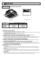
Series PLH Ceiling Cassettes
Indoor unit
[Model names]
PLH-1.6KKHC
PLH-2KKHC
PLH-2.5KKHC
This manual does not cover the
following outdoor units.
When
servicing them, please refer to the
service manual No.OC128 and
this manual in a set.
[Service Ref.]
PUH-1.6VKA2
PUH-2VKA2
PUH-2.5VKA2
[Service Ref.]
PLH-1.6KKHC
PLH-2KKHC
PLH-2.5KKHC
CONTENTS
INDOOR UNIT
FILTER
CHECK MODE
TEST RUN
REMOTE CONTROLLER
1. FEATURES ···········································2
2. PART NAMES AND FUNCTIONS ········3
3. SPECIFICATIONS·································6
4. DATA ·····················································9
5. OUTLINES AND DIMENSIONS··········13
6. WIRING DIAGRAM·····························15
7. REFRIGERANT SYSTEM DIAGRAM ······16
8. OPERATION FLOW-CHART ··············17
9. MICROPROCESSOR CONTROL·······21
10. TROUBLESHOOTING ························43
11. 4-WAY AIR FLOW SYSTEM ···············51
12. SYSTEM CONTROL ···························52
13. DISASSEMBLY PROCEDURE ···········57
14. PARTS LIST········································60
15. OPTIONAL PARTS ·····························64
The Slim Line.
From Mitsubishi Electric.
1
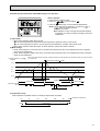
FEATURES
Series PLH Ceiling Cassettes
FILTER
CHECK MODE
TEST RUN
Indoor unit
Service Ref.
PLH-1.6KKHC
PLH-2KKHC
PLH-2.5KKHC
Remote controller
Cooling capacity/Heating capacity
W
Btu/h
4,400/4,650
5,400/5,800
6,300/7,200
15,000/15,900
18,400/19,800
21,500/24,600
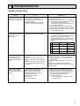
1.PURSUING CONPACTNESS
(1)Panel size and body volume reduced to 64% of previous models
The width and depth of the panel have been reduced by 19cm respectively,resulting in a compact model which fits smaller environments (like shops) perfectly.
(2)Multi-application panels flexibly adapt to installation conditions.
Space panel and Wide panel may be installed on ceilings with shallow depth using the exiting opening .
2."SMUDGE-FREE", PRECISELY TARGETED AIRFLOW SYSTEM
The new control system regulates airflow to prevent smudging. A projection inside the air passage distributes air evenly
over the top and bottom of the vane. Two projections on the air outlet work to prevent cooled air from rising to the
celling, and also to stop outside air being dragged into the cooled air stream.
3.AIRFLOW ADJUSTABLE TO ANY INDOOR ENVIRONMENT
Airflow can be adjusted according to celling height and the number of air outlets. "Wide Zoming Flow" creates anoptimum airflow for any indoor environment.
4.A FURTHER REFINEMENT OF COMFORT WITH NOISE SUPPRESION
The celling 4-way airflow cassette has a special "silent-design". The "2-Tap"system allows a choice between silent and
standard modes according to the height of the cellig. For ordinary residenced which have a low celling, selection of the
silent mode will result in remarkable noise reductions.
5.ECONOMICAL AND EASY MAINTENANCE
(1)Push-open grill
Filter clogging is widely recognized as a cause of reduced perfomance, but up until now it has been troublesome to
clean filters. With the "push-open grill" the fillter can be smoothly opened out at the push of a button, enabling speedy
cleaning.
(2)An unprecedented level of vane-cleaning
The unique airflow system prevents the intake of indoor air. Dewing therefore does not occur, and the vane is flockless.
The resulting level of dirt on the vane due to tobacco smoke, dust, etc. is very light,and can be wiped off easily with a
neutral detergent
(3)Long-life fillter
This new celling 4-way airflow cassette employs a long life fillter which requires no maintenance for up to 2,500 hours of
operation in general office environments. It adds uo to an ideal blend of comfort and low maintenance.
2
6.COMPACT DIMENSIONS MEAN EASY INSTALLATION
(1)Carefree suspension work with lightweight unit
The new unit weighs in at 20kg (9kg lighter than the previous model) and is easy to handle and install. What's more, suspension work is facillitated by compact dimensions ensuring a snug fit.
(2)Smooth installation with "one-direction"bolts
Suspension bolts can be fixes consistently from one direction easing suspension work.
(3)Trouble-free fitting work with slender refrigerant piping
Refrigerant piping has been reduced in size, and pipe-curving work at the installation site can now be completed quickly
and economically. In addition, refrigerant and drain piping are set at different corners, which means that flare connections
and drain piping heat insulation work can be smoothly and reliably implemented.
(4)Easy-access terminal and control panels for efficient wiring
When performing wiring work, progress can be checked on the power source terminal and control panels simply by
removing the electrical parts cover. Adress setting can also be done easily from beneath at a convenient angle.
(5)"One-push"to provisionally position front panel
Panel weight has been redused from 7kg to 3.7kg. The previous 3-step process for provisionally positioning the panel
has been streamlined, and now a simple "one-push" action at the diagonal corners fixed it into place, resulting in major
time-saving.
2
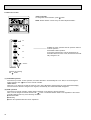
PART NAMES AND FUNCTIONS
● Indoor (Main) Unit
PLH-1.6KKHC
PLH-2KKHC
PLH-2.5KKHC
Filters
Remove dust and pollutants
from inhaled air
Horizontal Air Outlet
Sets airflow horizontal automatically
during cooling or dehumidifying.
Grill
Auto Air Swing Vane
Disperses airflow up and
down and adjusts the angle
of airflow direction.
Air Intake
Inhales air from room.
3
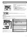
● Remote controller
● Once the controls are set, the
same operation mode can be
repeated by simply pressing the
ON/OFF button.
● Operation buttons
button
button
button
This switches between
continuous operation and
the timer operation.
This sets of switches the
current time. start time
and stop time.
This sets the ventilation
fan speed.
ON/OFF button
This switches between the
operation and stop modes
each time it is pressed.
The lamp on this butoon
lights during operation.
button
Press this button to
switch the cooler electronic dry (dehumidify)
automatic and heater
modes.
FILTER
CHECK MODE
TEST RUN
button
This adjusts the vertical
angle of the ventilation.
TEMP button
This sets the room temparature The temparature
setting can be performed
in 1°C units
Setting range
Cooler 19°C to 30°C
Heater 17°C to 28°C
This model name of the
remote controller is indicated.
FILTER button
This resets the filter service indication display.
240KA
button
This switches the horizontal fan motion ON and
OFF.
(This button does not
operate in this model)
4
CHECK-TEST RUN button
Only press this button to
perform an inspection
check or test operation
Do not use it for nomal
operation.
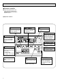
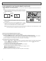
● Display
CENTRALLY
CONTROLLED display
This indicates when the unit is controlled by optional features such as
central control type remote controller.
display
The current time , start time and stop
time can be displayed in tensecond
intervals by pressing the time switch
button. The start time or stop time is
always displayed during the timer
operation.
In this display example on the bottom left, a condition where all display lamps light is shown for
explanation purposes although this differs from
actual operation.
display
This displays the air direction.
display
display
This indicates when the continous
operation and time operation modes
are set.
It also display the time for the timer
operation at the same time as when
it is set.
The selected fan speed is displayed.
display
FILTER
OPERATION MODE display
CHECK MODE
TEST RUN
This indicates the operation mode.
STANDBY display
This indicates when the standby
mode is set from the time the sleep
operation starts until the heating air
is discharged.
Operation lamp
This lamp lights during operation,
goes off when the unit stops and
flashes when amalfunction occurs.
240KA
FILTER Display
DEFROST display
This lamp lights when the filter need
to be cleaned.
This indicates when the defrost operation is performed.
CHECK display
This indicates when a malfunction
has occurred in the unit which should
be checked.
The temperature of the suction air is
displayed during operation. The display range is 8° to 39°C. The display
flashes 8°C when the actual temperature is less than 8° and flashes
39°C when the actual temperature is
greater than 39°C.
CHECK MODE
display
This displays the selected setting
temperature.
display
This lamp lights when electricity is
supplied to the unit.
TEST RUN
display
This display lights in the check mode
or when a test operation is performed.
Caution
● Only the display lights when the unit is stopped and power supplied to the unit.
● When power is turned ON for the first time the (CENTRAL CTRL) display appears to go off momentarily but this is not a malfunction.
● When the central control remote control unit, which is sold separately, is used the ON-OFF button,
button and
TEMP
button do not operate.
● “NOT AVAILABLE” is displayed when the k button are pressed.This indicates that this room unit is not equipped with the fan
direction adjustment function and the louver function.
5
3
Item
SPECIFICATIONS
Service Ref.
Function
Capacity
Btu/h
W
kW
REFRIGERANT PIPING
OUTDOOR UNIT
INDOOR UNIT
Total input
Service Ref.
Power supply(phase, cycle,voltage)
Input
kW
Running current
A
Starting current
A
External finish
Heat exchanger
Fan(drive) x No.
Fan motor output
kW
Airflow(Low-High)
K/min(CFM)
External static pressure
mmAq,Pa
Booster heater
kW
Operation control & Thermostat
Noise level(Low-High)
dB(A)
Cond. drain conn. O.D.
mm,(in.)
W
mm,(in.)
Dimensions
D
mm,(in.)
H
mm,(in.)
Weight
kg,(lbs)
Service Ref.
Power supply (phase, cycle, voltage)
kW
Input
A
Running current
A
Starting current
External finish
Refrigerant control
Compressor
Model
kW
Motor output
Starter type
Protection devices
Heat exchanger
Fan(drive) x No.
kW
Fan motor output
K/min(CFM)
Airflow
Defrost method
dB(A)
Noise level
W
mm,(in.)
D
mm,(in.)
Dimensions
H
mm,(in.)
kg,(lbs)
Weight
Refrigerant
kg,(lbs)
Charge
Liquid
mm,(in.)
Pipe size O.D.
Gas
mm,(in.)
Indoor
side
Connection method
Outdoor side
Height difference
Between the indoor &
Piping length
outdoor unit
6
PLH-1.6KKHC
Cooling
15,000
4,400
1.59
Heating
15,900[20,600]
4,650[6,050]
1.51[3.20]
PLH-1.6KKHC
Single, 50Hz, 220-240V
0.15
0.10[1.50]
0.64
0.45[6.28]
0.70
0.50[6.91]
Galvanized sheets with gray heat insulation
Plate fin coil
Turbo fan [direct) x 1
0.030
13-16(460-565)
0(direct blow)
[1.4]
Remote controller & built-in
32-37
32(1-1/4)
UNIT : 660(26)
PANEL : 760(30)
UNIT : 660(26)
PANEL : 760(30)
UNIT : 253(10)
PANEL : 30(1-1/8)
UNIT : 19(42)[20(44)]
PANEL : 3.7(8)[3.7(8)]
PUH-1.6VKA2
Single, 50Hz, 220-240V
1.44
1.41
6.74
6.60
33
Munsell 5Y 7/1
Capillary tube
Hermetic
RH247VFC
1.2
Line start
Inner thermostat, High pressure switch
Plate fin coil
Propeller (direct) x 1
0.065
45(1,590)
Reverse cycle
49
870(34-1/4)
295+24 (11-5/8 and 1)
650 (25-5/8)
53(117)
R-22
2.2(4.8)
9.52 (3/8)
15.88 (5/8)
Flared
Flared
Max. 40m
Max. 40m
Item
Service Ref.
Function
Capacity
Btu/h
W
kW
REFRIGERANT PIPING
OUTDOOR UNIT
INDOOR UNIT
Total input
Service Ref.
Power supply(phase, cycle,voltage)
Input
kW
Running current
A
Starting current
A
External finish
Heat exchanger
Fan(drive) x No.
Fan motor output
kW
Airflow(Low-High)
K/min(CFM)
External static pressure
mmAq,Pa
Booster heater
kW
Operation control & Thermostat
Noise level(Low-High)
dB(A)
Cond. drain conn. O.D.
mm,(in.)
W
mm,(in.)
Dimensions
D
mm,(in.)
H
mm,(in.)
Weight
kg,(lbs)
Service Ref.
Power supply (phase, cycle, voltage)
Input
kW
Running current
A
Starting current
A
External finish
Refrigerant control
Compressor
Model
Motor output
kW
Starter type
Protection devices
Heat exchanger
Fan(drive) x No.
Fan motor output
kW
Airflow
K/min(CFM)
Defrost method
Noise level
dB(A)
W
mm,(in.)
D
Dimensions
mm,(in.)
H
mm,(in.)
Weight
kg,(lbs)
Refrigerant
Charge
kg,(lbs)
Liquid
mm,(in.)
Pipe size O.D.
Gas
mm,(in.)
Indoor side
Connection method
Outdoor side
Height difference
Between the indoor &
Piping length
outdoor unit
PLH-2KKHC
Cooling
18,400
5,400
2.34
Heating
19,800[24,600]
5,800[7,200]
2.32[4.09]
PLH-2KKHC
Single, 50Hz, 220-240V
0.14
0.10[1.50]
0.65
0.45[6.28]
0.72
0.50[6.91]
Galvanized sheets with gray heat insulation
Plate fin coil
Turbo fan (direct) x 1
0.030
13-16(460-565)
0(direct blow)
[1.4]
Remote controller & built-in
32-37
32(1-1/4)
UNIT : 660(26)
UNIT : 660(26)
PANEL : 760(30)
UNIT : 253(10)
PANEL : 760(30)
UNIT : 19(42)[20(44)]
PANEL : 30(1-1/8)
PANEL : 3.7(8)[3.7(8)]
PUH-2VKA2
Single, 50Hz, 220-240V
2.20
9.86
2.22
45
9.95
45
Munsell 5Y 7/1
Capillary tube
Hermetic
NH38VMD
1.7
Line start
Inner thermostat, HP switch
Plate fin coil
Propeller (direct) x 1
0.065
45(1590)
Reverse cycle
49
870(34-1/4)
295+24 (11-5/8 add 1)
650 (25-5/8)
64(141)
R-22
2.2(4.8)
9.52 (3/8)
15.88 (5/8)
Flared
Flared
Max. 40m
Max. 40m
7
Item
Service Ref.
Function
Capacity
Btu/h
W
kW
REFRIGERANT
OUTDOOR UNIT
INDOOR UNIT
Total input
Service Ref.
Power supply(phase, cycle,voltage)
Input
kW
Running current
A
Starting current
A
External finish
Heat exchanger
Fan(drive) x No.
Fan motor output
kW
Airflow(Low-High)
K/min(CFM)
External static pressure
mmAq,Pa
Booster heater
kW
Operation control & Thermostat
Noise level(Low-High)
dB(A)
Cond. drain conn. O.D.
mm,(in.)
W
mm,(in.)
Dimensions
D
mm,(in.)
H
mm,(in.)
Weight
kg,(lbs)
8
Service Ref.
Power supply (phase, cycle, voltage)
kW
Input
A
Running current
A
Starting current
External finish
Refrigerant control
Compressor
Model
kW
Motor output
Starter type
Protection devices
Heat exchanger
Fan(drive) x No.
kW
Fan motor output
K/min(CFM)
Airflow
Defrost method
dB(A)
W
Noise level
mm,(in.)
D
mm,(in.)
H
Dimensions
mm,(in.)
Weight
kg,(lbs)
Refrigerant
Charge
kg,(lbs)
Liquid
mm,(in.)
Pipe size O.D.
Gas
mm,(in.)
Indoor side
Connection method
Outdoor side
Height difference
Between the indoor &
Piping length
outdoor unit
PLH-2.5KKHC
Cooling
21,500
6,300
2.60
Heating
24,600[31,700]
7,200[9,300]
2.33[4.87]
PLH-2.5KKHC
Single, 50Hz, 220-240V
0.14
0.10[2.20]
0.61
0.45[9.20]
0.67
0.50[10.12]
Galvanized sheets with gray heat insulation
Plate fin coil
Turbo fan (direct) x 1
0.030
14-17(495-600)
0(direct blow)
[2.1]
Remote controller & built-in
35-39.5
32(1-1/4)
UNIT : 660(26)
PANEL : 760(30)
UNIT : 660(26)
PANEL : 760(30)
UNIT : 253(10)
PANEL : 30(1-1/8)
UNIT : 20(44)[21(46)]
PANEL : 3.7(8)[3.7(8)]
PUH-2.5VKA2
Single, 50Hz, 220-240V
2.46
2.23
10.68
9.78
52
52
Munsell 5Y 7/1
Capillary tube
Hermetic
NH41VMD
2.0
Line start
Inner thermostat, HP switch
Plate fin coil
Propeller (direct) x 1
0.085
50(1764)
Reverse cycle
52
870(34-1/4)
295+24 (11-5/8 add 1)
850(34-1/4)
68(150)
R-22
2.8(6.2)
9.52(3/8)
15.88 (5/8)
Flared
Flared
Max. 50m
Max. 50m
4
DATA
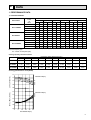
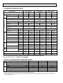
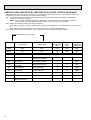
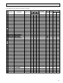
1. PERFORMANCE DATA
1) COOLING CAPACITY
Indoor
intake
air
WB:
Service Ref.
PLH-1.6KKHC
PLH-2KKHC
PLH-2.5KKHC
Outdoor intake air DB:
20
CA
25
P.C.
CA
30
P.C.
CA
35
P.C.
CA
40
P.C.
CA
45
P.C.
CA
P.C.
16
4,347
1.36 4,227
1.42 4,068
1.52 3,900
1.63 3,724 1.74 3,535 1.85
18
4,627
1.39 4,506
1.44 4,339
1.56 4,162
1.67 3,978 1.78 3,788 1.90
20
4,906
1.41 4,790
1.47 4,618
1.59 4,438
1.71 4,253 1.83 4,059 1.96
22
5,177
1.43 5,078
1.50 4,906
1.62 4,730
1.75 4,545 1.89 4,352 2.03
16
5,257
2.14 5,112
2.23 4,919
2.40 4,716
2.57 4,503 2.74 4,274 2.91
18
5,595
2.18 5,450
2.27 5,247
2.45 5,034
2.63 4,810 2.81 4,581 2.98
20
5,933
2.22 5,793
2.31 5,585
2.50 5,366
2.69 5,143 2.89 4,909 3.08
22
6,261
2.25 6,141
2.35 5,933
2.55 5,720
2.76 5,496 2.97 5,262 3.19
16
6,268
2.47 6,095
2.58 5,865
2.78 5,628
2.97 5,369 3.17 5,096 3.37
18
6,671
2.53 6,498
2.63 6,256
2.84 6,002
3.05 5,735 3.25 5,462 3.46
20
7,074
2.57 6,907
2.68 6,659
2.90 6,398
3.12 6,132 3.34 5,853 3.57
22
7,465
2.61 7,322
2.73 7,074
2.96 6,820
3.19 6,553 3.44 6,274 3.70
Note CA:Capacity (W)
P.C. :Power consumption (kW)
Cooling capacity correction factors
5m
10m
15m
Refrigerant piping length (one way)
20m
25m
30m
35m
40m
45m
50m
PLH-1.6KKHC
1.00
0.993
0.984
0.978
0.969
0.961
0.956
0.948
—
—
PLH-2KKHC
1.00
0.992
0.983
0.978
0.966
0.959
0.950
0.945
—
—
PLH-2.5KKHC
1.00
0.989
0.980
0.970
0.960
0.950
0.940
0.930
0.920
0.910
Service Ref.
Cooling performance curve(50Hz)
CAPACITY (RATIO)
1.4
INDOOR WB(°C)
1.2
1.0
22
20
18
16
0.8
0.6
TOTAL INPUT (RATIO)
1.4
22
20
18
16
1.2
INDOOR WB(°C)
1.0
0.8
0.6
0.4
-5
5
15
25 35 46
OUTDOOR DB(°C)
9
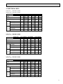
2) HEATING CAPACITY
Service Ref.
PLH-1.6KKHC
PLH-2KKHC
PLH-2.5KKHC
Indoor
intake
air
WB:
Outdoor intake air DB:
-10
CA
15
P.C.
CA
0
P.C.
CA
5
P.C.
CA
10
P.C.
CA
15
P.C.
CA
P.C.
15
3,169
1.12 3,625
1.23 4,126
1.36 4,669
1.49 5,249 1.62 5,874 1.77
20
3,031
1.20 3,482
1.33 3,970
1.46 4,494
1.60 5,055 1.75 5,653 1.90
25
2,916
1.28 3,340
1.42 3,813
1.56 4,329
1.71 4,885 1.87 5,488 2.04
15
3,996
1.77 4,570
1.95 5,203
2.15 5,887
2.35 6,618 2.57 7,407 2.80
20
3,822
1.90 4,391
2.10 5,005
2.31 5,667
2.53 6,374 2.77 7,128 3.01
25
3,677
2.02 4,211
2.24 4,808
2.47 5,458
2.71 6,160 2.97 6,919 3.23
15
4,616
1.82 5,280
2.01 6,010
2.21 6,801
2.43 7,645 2.65 8,556 2.88
20
4,415
1.96 5,072
2.17 5,782
2.38 6,546
2.61 7,363 2.85 8,234 3.10
25
4,248
2.09 4,864
2.31 5,554
2.55 6,305
2.80 7,115 3.06 7,993 3.33
Note CA:Capacity (W)
P.C. :Power consumption (kW)
Heating capacity correction factors
5m
10m
15m
Refrigerant piping length (one way)
20m
25m
30m
35m
40m
45m
50m
PLH-1.6KKHC
1.00
1.00
1.00
1.00
1.00
1.00
0.998
0.995
—
—
PLH-2KKHC
1.00
1.00
1.00
1.00
1.00
1.00
0.998
0.995
—
—
PLH-2.5KKHC
1.00
1.00
1.00
1.00
1.00
1.00
0.998
0.995
0.993
0.990
Service Ref.
Heating performance curve(50Hz)
CAPACITY (RATIO)
1.4
15
20
25 INDOOR DB (°C)
1.2
1.0
0.8
0.6
TOTAL INPUT (RATIO)
1.4
1.0
0.8
0.6
0.4
-12-10
10
25
20
15
1.2
-5
0
5
10 15
OUTDOOR WB(°C)
INDOOR DB (°C)
2. ELECTRICAL DATA
Indoor unit … 220V 50Hz 1phase
Outdoor unit…220V 50Hz 1phase
Indoor unit
PLH-1.6KKHC PLH-2KKHC
Outdoor unit PUH-1.6VKA2 PUH-2VKA2
Heat
Heat
Cool
Cool
Service Ref.
Mode
Input (kW)
0.12
Current (A)
0.60
Starting current (A)
0.66
4,550
[5,720]
1.40
[2.57]
0.08
[1.25]
0.41
[5.75]
0.45
[6.33]
0.67
5,700
[6,870]
2.22
[3.73]
0.08
[1.25]
0.42
[5.76]
0.46
[6.34]
Input (kW)
1.36
1.32
2.12
Current (A)
6.79
6.59
30
30
4,300
Total Input (kW)
1.48
Outdoor unit Indoor unit
Capacity (W)
Starting current (A)
PLH-2.5KKHC
PUH-2.5VKA2
Heat
Cool
0.63
6,900
[8,660]
2.25
[4.41]
0.09
[1.85]
0.46
[9.28]
0.80
[8.79]
2.14
2.41
2.16
9.83
9.93
11.18
10.02
43
43
52
52
5,300
2.24
0.12
0.61
6,200
2.53
0.12
0.57
Indoor unit … 230V 50Hz 1phase
Outdoor unit…230V 50Hz 1phase
Mode
PLH-1.6KKHC PLH-2KKHC
PUH-1.6VKA2 PUH-2VKA2
Heat
Heat
Cool
Cool
Capacity (W)
4,350
Total Input (kW)
1.54
Outdoor unit Indoor unit
Service Ref.
Indoor unit
Outdoor unit
Input (kW)
0.14
Current (A)
0.62
Starting current (A)
0.68
4,600
[5,890]
1.45
[3.01]
0.09
[1.38]
0.43
[6.02]
0.47
[6.62]
Input (kW)
1.40
Current (A)
Starting current (A)
0.69
5,750
[7,040]
2.27
[3.92]
0.09
[1.38]
0.44
[6.03]
0.48
[6.63]
1.36
2.16
6.76
6.57
32
32
PLH-2.5KKHC
PUH-2.5VKA2
Heat
Cool
0.65
7,050
[8,980]
2.29
[4.64]
0.09
[2.02]
0.43
[8.82]
0.47
[9.70]
2.18
2.44
2.20
9.78
9.87
10.94
9.86
44
44
52
52
5,350
2.29
0.13
0.63
6,250
2.57
0.13
0.59
Indoor unit … 240V 50Hz 1phase
Outdoor unit…240V 50Hz 1phase
Mode
PLH-1.6KKHC PLH-2KKHC
PUH-1.6VKA2 PUH-2VKA2
Heat
Heat
Cool
Cool
Capacity (W)
4,400
Total Input (kW)
1.59
Outdoor unit Indoor unit
Service Ref.
Indoor unit
Outdoor unit
Input (kW)
0.15
Current (A)
0.64
Starting current (A)
0.70
4,650
[6,050]
1.51
[3.20]
0.10
[1.50]
0.45
[6.28]
0.50
[6.91]
Input (kW)
1.44
Current (A)
Starting current (A)
0.72
5,800
[7,200]
2.32
[4.09]
0.10
[1.50]
0.45
[6.28]
0.50
[6.91]
1.41
2.20
6.74
6.60
33
33
PLH-2.5KKHC
PUH-2.5VKA2
Heat
Cool
0.67
7,200
[9,300]
2.33
[4.87]
0.10
[2.20]
0.45
[9.20]
0.80
[9.55]
2.22
2.46
2.23
9.86
9.95
10.68
9.78
45
45
52
52
5,400
2.34
0.14
0.65
6,300
2.60
0.14
0.67
11
3. STANDARD OPERATION DATA
Service Ref.
PLH-1.6KKHC
Total
Mode
Cooling
Heating
Cooling
Heating
Cooling
Heating
W
4,400
4,650
5,400
5800
6,300
7,200
Input
kW
1.59
1.51
2.34
2.32
2.60
2.33
PLH-1.6KKHC
PLH-2KKHC
PLH-2.5KKHC
1,50
1,50
1,50
240
240
Electrical circuit
Phase,Hz
Volts
V
Amperes
A
Outdoor unit Service Ref.
0.64
Discharge pressure
A
Mpa•G
0.65
240
0.45
0.45
PUH-2VKA2
PUH-2.5VKA2
1,50
1,50
1,50
240
240
240
V
Amperes
0.45
0.61
PUH-1.6VKA2
Phase,Hz
Volts
Refrigetrant circuit
PLH-2.5KKHC
Capacity
Indoor unit Service Ref.
Outdoor Indoor side
side
PLH-2KKHC
6.74
1.80
6.60
1.70
9.86
1.90
9.95
1.94
10.68
1.95
9.78
1.71
(kgf/G•G)
(18.3)
(17.3)
(19.3)
(19.8)
(19.9)
(17.4)
Mpa•G
(kgf/G•G)
0.54
(5.5)
0.40
0.46
0.34
(3.5)
0.50
(5.1)
0.36
Discahrge temperature
°C
78.7
77.2
84.0
86.4
82.8
76.0
Condensing temperature
°C
48.5
—
50.7
—
51.8
—
Suction temperature
°C
8.5
0.7
4.8
-1.8
6.7
-1.5
Ref. pipe length
m
5
5
5
5
5
5
DB°C
27
20
27
20
27
20
WB°C
19
15
19
15
19
15
DB°C
16.1
35.2
15.0
39.4
13.8
41.2
DB°C
35
7
35
7
35
7
WB°C
24
6
24
6
24
6
SHF
0.83
—
0.76
—
0.75
—
BF
0.21
—
0.21
—
0.14
—
Suction pressure
Intake air temperature
Discharge air temperature
Intake air temperature
(4.1)
(4.7)
(3.7)
The unit of pressure has been changed to Mpa based on international SI system.
f.G)
The conversion factor is : 1(Mpa.G)=10.2(kgf/f
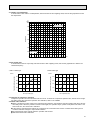
4. OUTLET AIR SPEED AND COVERAGE RANGE
High ceiling Standard
PLH-2.5KKHC
PLH-2KKHC
PLH-1.6KKHC
17.0
16.0
16.0
m3/min
Air flow
5.9
5.6
5.6
Air speed
m/sec.
6.4
6.0
6.0
Coverage range
m
18.0
17.0
17.0
Air flow
m3/min
6.3
5.9
5.9
Air speed
m/sec.
6.8
6.4
6.4
Coverage range
m
0
0
0
Total width of discharge outlets
mm
w The air coverage range is the value up to the position where the air speed is 0.25m/sec.
When air is blown out horizontally from the unit at the Hi notch position.
The coverage range should be used only as a general guideline since it varies according to the size of the room and the
furniture inside the room.
12
A
25~35
154
Wired panel
(Indication area)
75
65
186
A
Refrigerant piping side
Wiring arrangement opening side
Intake grille
(Air intake)
1
760
460
Air outlet
466
Air intake
2
660
42
117
Drain water release hole
117
25~35
Terminal block
for remote controller
Power terminal block
Terminal block
Control wire opening
Power switch wire opening
Suspension bolt lower edge
145
Suspension bolt M10
or W3/8
25~35
507
77
65~80
68
117
117
4-Auto vane
Vane motor
Grill
35
Intake grille opening closing side.
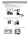
1/6/2/2.5
Optional multifunctional casement
Optional high performance filter
Note 3: For the installation of the optional high efficiency filter or optional
multiple casement, it requires minimum 440mm space between
transom and ceiling for the installation (Optional high
performance filter can be also installed).
Note 2: Electrical box may be removed for the service purpose. Make
sure to slack the electrical wire little bit for control/power wires
connection.
Note 1: For the installation of the optional humidifier(suspended type), it
requires minimum 360mm space between transom and ceiling.
Keep approximately
10 to 15mm space
between unit ceiling and ceilimg slab.
Inspection hole
(Drain up machine)
Ceiling side
66
Connect the attached
flexible pipe or socket.
Drain pipe
Connected to VP-25
13
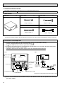
Ceiling hole
690~710
640
Suspension bolt pitch
+3
Ceiling hole
690~710
760
30
Suspension bolt pitch
64
460
Air outlet
66
660
115
466
Air intake
+3
25~35
2 (Gas)
Refrigerant pipe {15.88
Flaredconnection 5/8F
1 (Liquid)
Refrigerant pipe {9.52
Flaredconnection 3/8F
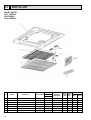
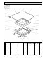
1. INDOOR UNIT
PLH-1.6KKHC/PLH-2KKHC/PLH-2.5KKHC
35
253
298
54 -2
135
435
54 -2
5
OUTLINES AND DIMENSIONS
Unit : mm
13
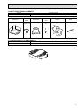
Unit : mm (inch)
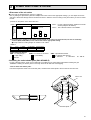
2.REMOTE CONTROLLER
FILTER
FILTER
CHECK
CHECK MODE
CHECK MODE
TEST RUN
TEST RUN
120
CHECK
18
130
83.5
Rear side wiring arrangement opening.
46
CAUTION
SW18
SW17
14
6
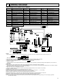
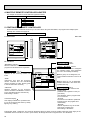
WIRING DIAGRAM
PLH-1.6KKHC/PLH-2KKHC/PLH-2.5KKHC
SYMBOL
NAME
SYMBOL
NAME
SYMBOL
NAME
R.B
REMOTE CONTROLLER BOARD
CN2L<I.B>
LOSSNAY CONNECTOR
X3<I.B>
VANE MOTOR RELAY
SW17<R.B>
ADDRESS SELECTOR
CN51<I.B>
CENTRALLY CONTROL CONNECTOR
X4<I.B>
FAN MOTOR RELAY
SW18<R.B>
FUNCTION SELECTOR
FAN2<I.B>
EMERGENCY OPERATION CONNECTOR
F1<I.B>
CN1<R.B>
PROGRAM TIMER CONNECTOR
F.C<I.B>
FAN PHASE CONTROL
LED1<I.B>
DC 12V POWER LED
CN2<R.B>
REMOTE SWITCH CONNECTOR
SW1<I.B>
MODE SELECTOR
LED2<I.B>
DC 5V POWER LED
MV
VANE MOTOR
SW2<I.B>
ADDRESS SELECTOR
CNP<I.B>
DRAIN PUMP CONNECTOR
LS
LIMIT SWITCH
SW3<I.B>
EMERGENCY OPERATION SWITCH
CN50<I.B>
DRAIN SENSOR CONNECTOR
H2
DEW PREVENTION HEATER
SW5, SW7<I.B> MODEL SELECTOR
DP
DRAIN PUMP
RT1
ROOM TEMP. THERMISTOR(0°C/15KΩ,25°C5.4KΩ)
SW6<I.B>
TWIN, TRIPLE SWITCH
DS
DRAIN SENSOR
RT2
INDOOR COIL THERMISTOR(0°C/15KΩ,25°C5.4KΩ)
SWA<I.B>
HIGH SEILING, NOISE SAVING SELECTOR
H1
HEATER
T
TRANSFORMER
SWB<I.B>
NUMBER OF AIR OUTLETS SELECTOR
FS1,2
THERMAL FUSE
MF
INNER THERMOSTAT FAN MOTOR
SWC<I.B>
OPTION SELECTOR
26H
HEATER THERMAL SWITCH
C1
FAN MOTOR CAPACITOR
ZNR<I.B>
VARISTOR
88H
HEATER CONNECTOR
TB2~6
TERMINAL BLOCK
X1<I.B>
DRAIN PUMP/D.HEATER RELAY
CNV<I.B>
VANE MOTOR CONNECTOR
I.B
INDOOR CONTROLLER BOARD
L
N
GRN / YLW
GRILL
I.B
TB2
10 5
MF
FUSE(6.3A)
POWER SUPPLY
~(1 PHASE)
220-240V 50Hz
220V 60Hz
BRN
H2
1 3
1 3
1 3
FAN1
CNV
CND
CND
FAN
VANE
S.U.M
POWER
T
YLW
ORN
RED
RED
BLU
BRN
BRN
BLU
RED
AC
14.2V
YLW
1 3 5
BRN
BRN
1 6 BLU
YLW
YLW
RED
WHT
BLK
2 7
WHT
DP
MV
1 2 3
C1
BRN
AC
4 3 2 1 11.1V
CN4T
1 3
LED2 5V POWER
TRANS
BRN 3
CNT
ORN 2
TRANS
FI
TRANSMISSION OUTDOOR
WIRE S
UNIT
DC 12V
3
2
YLW 1
X4
1 3 5
FAN2
SW2
SW5
SW6
SW1
3
2
ON
OFF
123456
1234
1234
1 2 3 4 5 6 7 8 9 10
I.B
STD
123
12
Shorting fig *1
SWA SWB
2
3
4
HEATER
CN24
CN51
CNTRALLY
CONTROL
1.6KKHC
2KKHC
PIPE
CN20
1
2
3
4
5
INTAKE
123
PLH-1.6,2,2.5KKHC (with heater)
TB2
POWER SUPPLY
-(1PHASE)
220-240V
50Hz
88H
RED
BLU 3 5
CN41
FS2
1
2
1
2
3
4
CN23
VANE
RT1
RT2
LOSSNAY
YLW
ORN
BRN
1
2
3
1
2
DS
123
BRN
1
2
CN2
1 2 3
1
2
TB5
R.B.
ON
OFF
1
2 SW18
OFF
ON
TB4
4321
SW17
H1
CN1
YLW 3
N
CN2L
1
2
1 2 3 4
HEATER
CN24
RED FS1
1
BLU
3
OUTDDOR
1
2
2.5KKHC
ON
OFF
SW7
TO REMOCON
CN30
CN21
fig: *1
Service Ref.
CN22
BLK
X1
BLK
ZNR
X3
1
2
CN50
3
DRAIN
4
5
ORN
X4
LED1 12V POWER
SW7
SW3 SWC OP
BLU
REMOCON
POWER
X1
TRANSMISSION WIRES DC12V
1
2
3
4
CN40
X3
BLK
F.C
1
TB3
TB4
YLW
1
88H
1
1 2 3 4 5
YLW
OFF
ON
87654321
26H
2
YLW
NOTES :
1. Since the indoor transformer (T)is connected with 240Vpower. If 220, 230v power is used. change the wiring connection showing fig: W2
fig:W2
When power supply is
230V
220V
240V YELLOW
230V ORANGE
220V RED
2.
3.
4.
5.
Since the outdoor side electric wiring may change be sure to check the outdoor unit electric wiring for servicing.
Indoor and outdoor connecting wires are made with polarities. make wiring matching terminal numbers.
: Connector.
Symbols used in wiring diagram above are. / : Terminal block,
Emergency operation
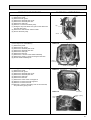
If remote controller or microcomputer fails but there is no other truble,. emergency operation is possible by setting dip switch (SW3<I.B>) on the indoor controller board.
[Check items]
(1)Make sure that no other trouble exists the outdoor unit. Trouble with the outdoor unit prevents emergency operation.
(If any trouble exists the outdoor unit error code “P8”will be displayed on the remote controller and the trouble position will be shown on the outdoor controller
board LED. See electric wiring diagram of the outdoor unit for details.)
(2)Make sure that there is no trouble with the indoor fan.
Emergency operation will be continuous run with the power ON/OFF (ON/OFF with the remote controller is not possible).
[Emergency operation procedure]
(1)Switch the fan connector on the indoor controller board from FAN 1 to FAN 2.
(2)Set the dip switch (SW3<I.B>) on the indoor controller board to 1 on and 2 off for cooling and 1 - 2 on for heating.
(3)Turn on the outdoor unit side circuit breaker, then the indoor unit side circuit breaker.
(4)During emergency operation indoor fan runs at High speed but auto-vane does not work.
(5)Thermostat will not function. Cold air blows out for defrosting during heating thus do not operate defrosting for a long time.
(6)Emergency cooling should be limited to 10 hours maximum. (the indoor unit heat exchanger may freeze).
(7)After every operation, switch the fan connector to FAN1, and set all dip switches (SW3<I.B>) to OFF.
NOTE: If the drain water lift up mechanism is identified to be defective with the microcomputer doctor during cooling, do not use emergency operation
(it causes drain overflow)
15
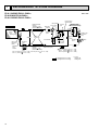
7
REFRIGERANT SYSTEM DIAGRAM
PLH-1.6KKHC/PUH-1.6VKA2
PLH-2KKHC/PUH-2VKA2
PLH-2.5KKHC/PUH-2.5VKA2
Unit : mm
High pressure
control switch
Oil separator
Refrigerant pipe
(option)
15.88mm( 5/8")
(with heat insulator)
Indoor unit
4-way valve
Service
port
Ball valve
Strainer
Outdoor unit
Outdoor heat exchanger
Flexible tube
Indoor
heat
exchanger
Service
port
Strainer
Outdoor coil
thermistor
(TH)
Flared
connection
Bypass
valve
Restrictor
valve
Accumulator
Indoor coil
thermistor
(RT2)
Distributor
with
strainer
Restrictor
valve
Compressor
Refrigerant pipe
(option)
9.52mm( 3.8")
(with heat insulator)
Capillary
tube
PLH-1.6 (O.D.3.2 I.D.1.6-r630) PLH-2.5 (O.D.3.2
PLH-2 (O.D.3.2 I.D.1.8-r630)
Strainer
Ball valve
(with service port)
I.D.1.8-r430)
PLH-1.6 (O.D.3.2
PLH-2 (O.D.4.0
PLH-2.5 (O.D.4.2
I.D.1.8 -r430)
I.D.2.0 -r430)
I.D.2.4-r1550)
Refrigerant flow in cooling
Refrigerant flow in heating
16
R.V.coil
Heating ON
Cooling OFF
Capillary
tube
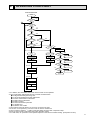
8
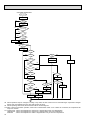
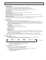
OPERATION FLOW-CHART
MAIN OPERATION
START
Power circuit
breaker
1
NO
YES
YES
Check SW
ON twice
NO
Operation SW
ON
w1
YES
NO
“OFF” timer
YES
NO
NO
Set time
complete
“ON” timer
NO
YES
YES
YES
Set time
complete
w2
NO
NO
Trouble
Remote controller
operation display
YES
STOP
Trouble STOP
PROTECTION DEVICE
SELF HOLD RELEASE
PROTECTION DEVICE
SELF HOLD
Operating mode
(COOL)
NO
Operating mode
(DRY)
w3
Remote controller
indicator lamp OFF
Remote controller
trouble display
NO
Operating mode
(HEAT)
Indoor side
Fan STOP
w4
NO
w6
Operating mode
(FAN)
NO
Auxiliary heater OFF
YES
COOL operation
YES
DRY operation
YES
HEAT operation
YES
w7
FAN operation
Auto COOL/HEAT
operation
Outdoor side
w5
Compressor OFF
Fan STOP
Four-way valve OFF
w1 In addition, the centralized control and remote control can be operated.
w2 The modes which indicate the sources of trouble are listed below.
● EO-Signal transmitting/receiving error
● P1-Room temperature thermistor malfunction
● P2-Indoor coil thermistor malfunction
● P4-Drain sensor malfunction
● P5-Drain overflow
● P6-Coil frost/overheat protection
● P7-System error
● P8-Outdoor unit trouble
w3 The CHECK swich will show if an error has occurred in the past.
w4 Fan runs on low speed for 1 minute in order to remove overheat air.
w5 The 3-minute (6 minutes … heating mode) time-delay functions after compressor stops.
w6 FAN or AUTO mode is selected by the indoor dipswitch setting.
w7 In FAN mode, fan speed and vane operation depend on the remote controller setting. (Compressor is OFF.)
17
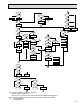
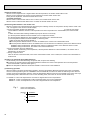
COOLING OPERATION
COOL operation
Four-way valve/OFF
NO
Initial
COOLING
w8
YES
Vane initial
setting
Vane
55 deg downward angle
70 deg downward angle
NO
YES
NO
Fan speed
LOW
YES
NO
Vane setting notch
Downward discharge
1 hour
YES
Vane horizontal
airflow
w9
NO
Compressor
thermostat
ON
YES
NO
Allowance
cancel
NO
YES
3-minute
time delay
YES
6-minute
time delay
NO
3-minute
compressor operation
NO
Allowance
period
NO
6 minute
time delay
NO
YES
Allowance set
w10
Coil frost protection
YES
YES
Coil frost
prevention
NO
w11
NO
Cooling area
YES
NO
10-minute
compressor operation
NO
YES
1 min continue
YES
Allowance cancel
FAN speed
LOW
Coil frost
protection
YES
NO
NO
Indoor coil
tempreature is
10°C or higher
16-minute
compressor operation
YES
Indoor pipe
temperature is
1°C or lower
NO
Compressor ON
YES
YES
Coil frost
prevention
NO
FAN speed
LOW 5 min
elapse
NO
YES
Outdoor unit
trouble
3-minute
time delay
Coil frost
prevention release
Compressor OFF
1
w8 When operation stops or changes to cooling or dry mode, the auto vane tums to a horizontal angle. If operation changes
during auto vane SWING, the auto vane will continue to swing.
w9 When operating TEST RUN, the thermostat will be continuously ON.
w10 After 3 minute compressor operation, if the indoor coil thermistor reads -15°C or below for 3 minutes, the compressor will
stop for 6 minutes.
w11 Cooling area : Indoor coil temperature is more than 5 degrees above the room temperature.
Heating area : Indoor coil temperature is more than 5 degrees below the room temperature.
FAN area
: Indoor coil temperature is within 5 degrees either way of the room temperature.
18
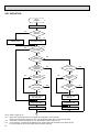
HEATING OPERATION
A
Heat operation
NO
Initial
HEATING
w11
Heating area
w15
PLH KKHC
NO
YES
NO
Vane intial setting
Vane setting notch
NO
YES
Defrost release
Defrost
30 min. elaspe
NO
Outdoor unit trouble
NO
Indoor coil
thermstor is 60°C
or higher
NO
FAN speed
Low notti
NO
Four-way valve ON
1
YES
Hor adjust
in process
YES
Airflow 10% up
NO
YES
NO
10-minute
compressor
operation
YES
NO
YES
Compressor
thermostat ON
3 min.restart
prevention
Allowance cancel
Indoor piping
-15°C or lower
YES
Heating
area
NO
Auxiliary heater
ON
NO
FAN STOP
FAN SPEED very low
w11
NO
YES
Airflow area
20 min.elapse
YES
w11
Compressor OFF
NO
FAN SPEED
Low
NO
Auxiliary heater
thermostat ON
YES
YES
Indoor piping
60°C or higher
Auxiliary heater ON
FAN SPEED
Low 2 min.
elapse
YES
NO
FAN SPEED
setting nitch
Hot adjust
release
YES
Auxiliary heater OFF
Compressor ON
FAN SPEED
Very low airflow
YES
NO
A
Hot adjust start
Outdoor unit
trouble
B
YES
Indoor piping
55°C or lower
6 min. restart
prevention
YES
HOT adjust
6 min. elapse
B
Allowance cancel
NO
2
Indoor piping
35°C or higher
NO
NO
YES
NO
FAN setting notch
YES
Compressor ON
w9
NO
NO
2
YES
YES
Defrosting
3-minute
Auxiliary heater
OFF
Airflow area
Heating area
w10
Outdoor unit
trouble
Overheat remote
START
NO
NO
Airflow area
Cooling area
NO
Indoor unit
70°C or higher
YES
YES
Defrost operation
START
Allowance
period
Four-way valve
OFF
YES
Overload protect
NO
6-minute restart
prevention
Allowance set
1
Compressor OFF
AUTOMATIC COOLING/HEATING OPERATION
Auto COOL/HEAT
operation
NO
1
w16
Initial mode
w17
YES
NO
T1 >
=T0
YES
COOL mode
COOL mode
HEAT mode
NO
YES
NO
NO
T1 < (T0 - 2)
YES
After 15min.
T1<(T0-2)
YES
YES
After 15min.
T1>(T0 + 2)
YES
NO
NO
COOL operation
T1>(T0 + 2)
HEAT operation
1
HEAT operation
Cool mode
set
1
w15 ( i ) Until Low airflow is set while hot adjustment
( ii )While defrosting (FAN STOP)
(iii)When thermostat is OFF
In the case of( i ), (ii) and (iii) above, airflow is horizontal regardless the VANE setting.
w16 When AUTO operation is started, COOL or HEAT mode is selected automatically.
w17 T1 : Room temperature.
To : Set temperature
19
DRY OPERATION
DRY
operation
Four-way valve / OFF
NO
Initial dry
operation
w8
YES
Vane
setting notch
Vane initial setting
YES
Room tempereature is
18°C or lower
w12
NO
NO
During
compressor ON
YES
3-minute
compressor
operation
NO
NO
YES
NO
w9
Compressor &
thermostat ON
YES
Compressor &
thermostat
ON
NO
Compressor ON
time completes
10-minute
compressor
OFF
NO
YES
YES
w13
10-minute compressor
OFF timer start
Compressor ON
time set
Compressor OFF
Compressor ON
w14
w14
Fan speed LOW
1
w8—9 Refer to page 26~27.
w12 When room temperature is 18°C or below, the compressor cannot operate.
When room temperature rises over 18°C, the compressor starts after a 3-minute time delay.
w13 Compressor ON time is decided by room temperature. Refer to page 26~27.
w14 In dry operation, compressor ON makes the fan speed LOW and compressor OFF stops the fan.
It is not possible to set the fan speed with the remote controller
20
w9
NO
YES
Fan STOP
YES
3-minute
time delay
9
MICROPROCESSOR CONTROL
1.OUTLINE OF MICROPROCESSOR CONTROL
INPUT to remore controller
● OFF-ON switching.
● COOL/DRY-AUTO-HEAT selector switching.
● Thermostat setting.
● TIMER mode selector-switching and Timer
setting.
● HIGH-LOW fan speed switching.
● AUTO Vane selector (AIR DISCHARGE)
switching.
● TEST RUN switching.
● CHECK mode switching.
(Self diagnostic trouble shooting)
Remote controller board
● Processes and transmits
orders.orders.
OUTPUT to remote controller
Remote controller
● LCD indicator
FILTER
CHECK MODE
TEST RUN
240KA
Indoor
unit
12VDC
Non-polar, two-wire cable
maxinmum length 500 meters
Signal
INPUT from indoor unit
● Room temperature thermistor (RT1)
● Indoor coil thermistor (RT2)
● Drain sensor
OUTPUT to indoor unit
Indoor controller board
● Receives orders from remote controller and
temperature data from indoor unit.
● Processes orders and data.
● Controls indoor and outdoor operation.
● Self diagnostic function.
w System control operation.
w Emergency operation.
w Set by dipswitch on indoor controller board.
● Transmits the power to remote controller.
● Compressor protectiondevice working
● Defrosting
START-STOP
● Fan speed control.
● Crankcase heater control
ON-OFF.
● Self diagnostic function
Outdoor unit
12VDC
Independent Control of
Outdoor Unit
Polar three-wire cable
1
2
3
OUTPUT to outdoor unit
1 2 3
● Autovane’s angle setting.
● Booster heater ON-OFF Control.
● Drain pump : ON-OFF.
● Emergency stop.
● Compressor and
outdoor fan : ONOFF
● Operation mode
change :COOLHEAT.
21
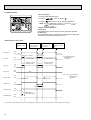
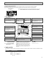
2. INDOOR UNIT CONTROL
2-1COOL operation
<How to operate>
1 Press POWER ON/OFF button.
2Press the
button to display “
”.
3Press the
TEMP button to set the desired temperature.
NOTE: Set temperature changes 1°C when the
or
button is pressed one time.
FILTER
CHECK MODE
TEST RUN
240KA
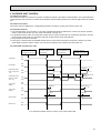
<COOL operation time chart>
Operation starts by
POWER button
ON.
Room temperature
becomes equal to
set temperature.
Room temperature
rises above set
temperature.
Operation stops by
POWER button
OFF.
ON
Thermostat
OFF
ON
Indoor fan
LOW or HIGH
OFF
Initally 30 degrees
(Changeable by remote controller setting)
30
Auto vane
LOW or HIGH
discharge
position
30
discharge
position
3 minutes
Drain pump
ON
OFF
ON
Booster heater
OFF
Compressor
OFF
OFF
ON
Minimum 3 minutes
w1
w1 Even if the room temperature rise above the set temperature during this period, the compressor will not start until this period has ended.
(1) Compressor control
1 3-minute time delay
To prevent overload, the compressor will not start within 3 minutes after stop.
2 The compressor runs when room temperature is higher than set temperature.
The compressor stops when room temperature is equal to or lower than the set temperature.
3 The compressor stops in check mode or during protective functions.
4 Coil frost prevention
To prevent indoor coil frost, the compressor will stop when the indoor coil thermistor (RT2) reads 1°C or below after the
compressor has been continuously operated for at least 16 minutes or more. When the indoor coil temperature rises to
10°C or above, the compressor will start after a 3-minute time delay.
NOTE : By turning OFF the dipswitch SW1-5 on indoor controller board, the start temperature of coil frost prevention
changes from 1°C to -3°C.
22
5 Coil frost protection
When indoor coil temperatuer becomes -15°C or below, coil frost protection will proceed as follows.
<Start condition>
After the compressor has been continuously operated for 3 minutes or more,and the indoor coil temperature has been 15° or below for 3 minutes,the coil frost protection will start.
<Coil frost protection>
Compressor stops for 6 minutes,and then restarts.
lf the start condition is satisfied again during the first 10 minutes of compressor operation, both the indoor and outdoor
units stop, displaying a check code of“P8”on the remote controller.
<Termination conditions>
Coil frost protection is released when the start condition is not satisfied again during the allowance, or when the COOL
mode stops or changes to another mode.
(2) Indoor fan control
Indoor fan speed LOW/HIGH depends on the remote controller setting.
However, if an outdoor unit abnormality is detected, the indoor fan speed will be LOW, regardless of the remote controller
setting.
When the outdoor unit abnormality detection is released and the fan speed returns to the set speed, the quiet cycle control
will work.
(a) Normal control
( i ) Fan speed LOW/HIGH depends on the remote controller setting regardless of the thermostat ON/OFF.
(ii) Fan speed will remain on LOW if an abnormality in outdoor unit is detected. (5 minutes)
When the abnormality detection is released, the fan speed returns to the set speed.
5 minutes
SET
5 minutes
SET
LOW
LOW
OFF
1 Start-up of outdoor unit abnormality detection.
2 Release of outdoor unit abnormality detection.
3 Unit stop due to outdoor unit abnormality
with P8 indication.
NOTE 1 : Fan stops immediately if the unit stops or the check mode is started.
23
(3) Auto vane control
Auto vane position is set to 30degrees airflow at the start-up of COOL operation. It can then be changed by the remote
controller.
(a) Stop mode (fixed operation)
( i ) At start-up of COOL operation, the auto vane is set to 10 degrees airflow direction.
( ii ) Airflow direction can be changed with
botton.
1 Fan speed : LOW
55°
30°
70°
SWING
(SW5-3:OFF/ON)
2 Fan speed : HIGH
30°
45°
55°
70°
SWING
(SW5-3:OFF/ON)
(b) SWING mode
( i ) The vane motor turns ON when the SWING mode is selected.
The vane motor is continuously ON during SWING mode.
<AUTO RETURN>
1 Fan speed : LOW
30
55
AUTO RETURN
70
AUTO RETURN
2Fan speed : HIGH
30
45
55
70
When 55 degrees or 70 degrees airflow discharge is selected with the LOW fan speed in COOL operation, “AUTO
RETURN” will appear below the temperature display. One hour later, the airflow direction returns to 30 degrees automatically and “AUTO RETURN” will disappear. If the airflow direction is set to 30 degrees during “AUTO RETURN” indication,
the time counting for AUTO RETURN is cancelled.
24
<Auto vane drive>
(a) The auto vane is driven by a 2.5 rpm motor.
(b) Airflow direction can be selected between the No.1 and No.2 setting. (Initial setting is No.1)
1
2
3
4
30°
45°
55°
70°
(c) Vane motor drive time
Airflow direction change
Unit : sec
50Hz
Downward C → Horizontal 4→1
Rise
Horizontal → Downward A 1→2
2.4
Downward A → Downward B 2→3
1.3
Downward B → Downward C 3→4
2.3
(d) Airflow direction is based on the horizontal position detected by the vane motor limit switch. When the horizontal position can not be determined, the vane motor will remain ON until it is determined.
1 If the horizontal position still can not be detected, despite the 10minute detection, the vane motor will turn OFF.
Remote controller indication continues.
2 After, if the vane motor receives the “auto vane ON” command again, it will restart detecting the horizontal position.
If the horizontal position still can not be determined, despite the 10-minute detection, the vane motor will turn OFF.
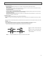
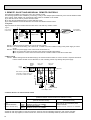
(4) Detecting abnormalities in the outdoor unit
After the compressor has been continuously operated for 3 minutes, if the difference between the indoor coil temperature
and room temperature is out of RANGE C for 1 minute, the indoor fan speed will turn to LOW. Five minutes later, if the difference is still out of RANGE C,the outdoor unit is functioning abnormally. Thus, the compressor stops and check code
“P8” appears on remote controler.
RANGE A : Indoor coil temperature is more than 5 degrees above room temperature.
RANGE B : Indoor coil temperature is within 5 degrees either way of room temperature.
RANGE C : Indoor coil temperature is more than 5 degrees below room tempetature.
Indoor coil temperature
minus room temperature
(degree)
+5
RANGE A
0
RANGE B
-5
RANGE C
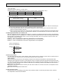
(5) Drain pump control
The drain pump works in COOL or DRY operation. When operation stops or changes to HEAT mode, the drain pump continues to operate for 3 more minutes. The drain pump does not work in check mode.
<Drain sensor>
When both the drain pump and unit are operating, the drain sensor detects the temperature. This temperature tells
whether the drain water level is above or under the drain sensor. If the drain water level rises above the drain sensor due
to a drain pump malfunction, the unit will stop operating in order to prevent drain from overflowing. The check code “P5” on
the remote controller will display this occurrence. When both of the following conditions are satisfied, the drain sensor is
determined to be under water.
● Though the drain sensor has been heated by the drain sensor heater for more than 40 seconds, its temperature rise is
less than 20 degrees.
● The drain sensor temperature is below 63°C.
(6) Dew prevention heater
To prevent dew from accumulating on the grill, the dew prevention heater is continuously ON during COOL operation.
It is independant of the thermostat ON/OFF
25
2-2 DRY operation
<How to operate>
1 Press POWER ON/OFF button.
2 Press the
FILTER
button to display “
”
CHECK MODE
TEST RUN
3 Press the
TEMP button to set the desired temperature.
NOTE: The set temperature changes 1°C when the
button is pressed one time.
Dry 19 to 30°C
240KA
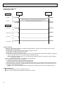
<DRY operation time chart>
Operation starts by
POWER button
ON.
Room temperature
becomes equal to
set temperature.
Room temperature
rises above set
temperature.
Operation stops by
POWER button
OFF.
ON
Thermostat
OFF
LOW speed
LOW speed
ON
Indoor fan
Auto vane
OFF
30
discharge
position
Initally 30 degrees discharge
(Changeable by remote controller setting)
30
discharge
position
3 minutes
Drain pump
ON
OFF
ON
Booster heater OFF
ON
Compressor
OFF
OFF
Minimum 3 minutes w1
w1 Even if the room temperature rise above the set temperature during this period, the compressor will not start until this period has ended.
(1) Compressor control
13-minute time delay
To prevent overload, the compressor will not start within 3 minutes after stop.
2The compressor runs when the room temperature is higher than the set temperature.
The compressor stops when the room temperature is equal to or lower than the set temperature.
3The compressor stops in check mode or during protective functions.
26
or
4The compressor will not start when the room temperature is below 18°C.
The compressor starts intermittent operation when the power is turned ON with room temperature above 18°C. The compressor ON/OFF time depends on the thermostat ON/OFF and the following room temperatures.After 3-minute compressor operation,
● If the room temperature thermistor reads above 28°C with thermostat ON, the compressor will operate for 6 more minutes and then stop for 3 minutes.
● If the room temperature thermistor reads 26°C~28°C with thermostat ON, the compressor will operate for 4 more minutes and then stop for 3 minutes.
● If the room themperature thermistor reads 24°C~26°C with thermostat ON, the compressor will operate for 2 more
minutes and then stop for 3 minutes.
● If the room temperature thermistor reads below 24°C with thermostat ON, the compressor will stop for 3 minutes.
● If the thermostat is OFF regardless of room temperature, the compressor will stop for 10 minutes.
5Coil frost protection
Coil frost protection in DRY operation is the same as in COOL operation.
6Coil frost prevention
Coil frost prevention does not operate in DRY operation.
(2) Indoor fan control
The indoor fan runs on LOW speed during compressor operation. The fan speed cannot be changed with the remote controller. Also, the indoor fan does not run during compressor OFF.
(3) Auto vane & drain pump controls
Same as in COOL operation.
(4) Detecting abnormalities in the outdoor unit
An abnormality in the outdoor unit can not be detected in DRY operation.
27
2-3 HEAT operation
<How to operate>
1 Press POWER ON/OFF button.
2 Press the
FILTER
button to display “
”.
CHECK MODE
3 Press the
TEST RUN
TEMP button to set the desired temperature.
NOTE: The set temperature changes 1°C when the
button is pressed one time.
Heat 17 to 28°C
<Display in HEAT operation>
or
[DEFROST]
240KA
The [DEFROST] symbol is displayed during the defrost operation.
[STAND BY]
The [STAND BY] symbol is displayed from the time the heating operation starts until the heated air begins to blow.
<HEAT operation time chart>
Operation starts by
POWER button
ON.
Room temperature
becomes equal to
set temperature.
Room temperature
rises above set
temperature.
Operation stops by
POWER button
OFF.
ON
Thermostat
OFF
Extra LOW w 1
Extra LOW w 1
LOW
ON
Indoor fan
LOW or HIGH
LOW or HIGH
OFF
Depends on remote
ON
Horizontal controller setting
Horizontal
w1 Changeable by indoor
dipswitch SW1-7
and SW1-8.
Depends on remote
controller setting
Auto vane
OFF
ON
Drain pump
OFF
OFF
OFF---during
ON
Booster heater
OFF
Hot adjustrment
Hot adjustrment
ON
Compressor
OFF
Minimum 3 minutes w 2
ON
Power ON lamp
OFF
From POWER ON until
warm begins to blow
ON
STAND BY lamp
OFF
w2 Even if the room temperature falls below the set temperature during this period, the compressor will not start until this period has ended.
28
thermostat OFF
hot adjustment
defrosting
(1) Compressor control
13-minute time delay
To prevent overload, the compressor will not start within 3 minutes after stop.
2The compressor runs when the room temperature is lower than the set temperature.
The compressor stops when the room temperature is equal to or higher than the set temperature.
3The compressor stops in check mode or during protective functions.
4Overheat protection
<Start condition>
When the indoor coil thermistor reads 70°C or above, the overheat protection will start.
<Overheat protection>
The compressor stops for 6 minutes, and then restarts.
If the start condition is satisfied again within 10 minutes of compressor operation, both the indoor and outdoor units stop,
displaying a check code of “P6” on the remote controller.
<Termination conditions>
Overheat protection is terminated when the start condition is not satisfied again during the allowance (10-minute compressor operation), when operation mode changes to other mode, or when thermostat turns OFF.
(2) Indoor fan control
(a) Normal control
( i )The indoor fan runs on EXTRA-LOW speed during the thermostat OFF.
EXTRA-LOW speed can be changed to LOW or HIGH speed by setting the dipswitch SW1-7 and SW1-8, If the
indoor coil temperature becomes more than 5 degrees below the room temperature during the thermostat OFF, the
indoor fan will stop. After, when the indoor coil temperature becomes within 5 degrees of room temperature, the
indoor fan will run on EXTRA-LOW speed.
( ii )Hot adjustment
Hot adjustment is a warm-up for HEAT operation
<Start conditions>
The hot adjustment works under any of the follwing conditions.
● HEAT operation starts.
● Defrosting ends.
● Thermostat turns ON.
<Hot adjustment>
Initially, the indoor fan runs on EXTRA-LOW speed. When 5 minutes have passed or the indoor coil temperature
exceeds 35°C, the fan speed changes to LOW. Two minutes later, the hot adjustment ends. Then, the fan speed
depends on the remote controller setting.
(iii)The indoor fan stops when the indoor coil temperature is within 5 degrees either way of room temperature.
(iv)To eliminate the remaining heat, the indoor fan runs for the first 1 minute after the booster heater is turned OFF.
(3) Auto vane control
(a) STOP mode (fixed operation)
( i ) The airflow direction at the start-up of HEAT operation is the same as that of the previous operation.
( ii ) The airflow direction can be charged by the remote controller setting.
30°
45°
55°
70°
SWING
(SW5-3 : OFF/ON)
In the following cases, airflow direction becomes 30° regardless of the remote controller setting.
1 During the hot adjustment with fan speed at EXTRA-LOW
2 During defrosting within door fan OFF
3 During the thermostat OFF
(b) SWING mode
( i ) The vane motor turns ON when the SWING mode is selected.
The vane motor is continuously ON during SWING mode.
( ii ) In the following cases, the airflow direction is 30 regardless of the remote controller setting.
1 During the hot adjustment with fan speed at EXTRA-LOW
2 During defrosting with indoor fan OFF
3 During thermostat OFF
29
(4) Booster heater control
When the room temperature is 3 degrees below the set temperature, the booster heater will turn ON.
When the room temperature is equal to the set temperature, booster heater will turn OFF.
During the hot adjustment, the booster heater will not work.
<Overheat prevention>
When the indoor coil thermistor rises to 60°C or above, the booster heater cannot work.
When the indoor coil thermistor falls to 55°C or below, the booster heater can work.
(5) Detecting abnormalities in the outdoor unit
When the outdoor unit is determined to be abnormal by the following causes, the compressor will stop and the check code
“ P8 ” will appear on the remote controller display.
w1 (See the next page.)
1During compressor ON after hot adjustment
1If the difference between the indoor coil temperature and room temperature is in the RANGE B, the indoor fan will
stop.
2 Within 20 minutes after entering RANGE B (except for the first 10 seconds),
a) If the temperature difference enters RANGE A, the hot adjustment stasrts,
b) If the temperature difference is still in RANGE B, the outdoor unit is deemed abnormal.
c) If the temperature difference enters RANGE C, defrosting starts.
Within 20 minutes after entering RANGE C,
●If the temperature difference does not return to RANGE B, the outdoor unit is deemed abnormal.
●If the temperature difference returns to RANGE B, the next 20 minutes is an allowance period. If the difference enter
RANGE A during the allowance, defrosting ends and the hot adjustment starts. If the difference does not enter
RANGE A during the allowance, the outdoor unit is deemed abnormal.
2During compressor ON in hot adjustment
After 30 minutes of defrosting in hot adjustment, if the temperature difference is still in RANGE C, the outdoor unit is
determined to be abnormal.
3 During compressor OFF
After 20 minutes of thermostat OFF, if the indoor coil thermistor reads -25°C or below, the outdoor unit is determined to
be abnormal.
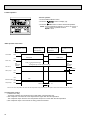
(6) Indoor coil thermistor abnormality detection
An abnormality can be detected during compressor ON, except for the following.
●For the first 30 minutes after the temperature difference between the indoor coil temperature and room temperature
enters the RANGE C.(See the below figure 1.)
●When the temperature difference enters the RANGE C until it moves to the RANGE B.
(7) Defrosting operation
After the outdoor unit starts the defrosting operation, when the temperature difference beetween the indoor coil temperature and room temperature gets out of RANGE A and into RANGE B, the indoor unit starts the defrosting mode. After the
outdoor unit stops the defrosting operation, when the temperature difference returns to the RANGE A, the indoor unit stops
the defrosting mode. While the indoor unit is in the defrosting mode, the indoor fan and the booster heater stop.
w1 RANGE A : Indoor coil temperature is more than 5 degrees above room temperataure.
RANGE B : Indoor coil temperature is within 5 degrees either way of room temperature.
RANGE C : Indoor coil temperature is more than 5 degrees below room temperature
Fig.1
Indoor coil temperature
minus room temperature
(degree)
+5
RANGE A
0
RANGE B
-5
30
RANGE C
2-4 AUTO operation (Automatic COOL/HEAT change over operation)
<How to operate>
1 Press POWER ON/OFF button.
2 Press the
button to display “
”.
FILTER
3 Press the
CHECK MODE
TEST RUN
TEMP button to set the desired temperature.
NOTE: The set temperature changes 1°C when the
or
button is pressed one time.
Automatic 19 to 28°C
●“AUTOMATIC” works to change by itself the operation
mode either to cooling or heating according to the room
temparature.
240KA
(1) Initial mode
1 When AUTO operation starts after unit OFF.
● If the room temperature is higher than the set temperature, operation starts in COOL mode.
● If the room temperature is equal to or lower than the set temperature, operation starts HEAT mode.
2 When AUTO operation starts after COOL or HEAT operation, the previous mode continues.
(2) Mode change
1 HEAT mode changes to cool mode when 15 minutes have passed since the room temperature became 2 degrees
above the set temperature.
2 COOL mode changes to HEAT mode when 15 minutes have passed since the room temperature became 2 degrees
below the set temperature.
To:Set temperature (19
(degree)
28
)
When room temperature becomes 2degrees above the set temperature, the operation mode can not be changed
for 15 minutes.
Mode change (HEAT
COOL)
To + 2
To + 1
To
To - 1
To - 2
15 minutes
Start
Minimum 3 minutes
COOL mode
HEAT mode
Compressor
Mode change
(COOL HEAT)
15 minutes
HEAT mode
ON
OFF
Minimum 3 minutes
(3) Temperature range
AUTO operation is available under the outside air temperatures as follows.
-9
0
10
20
30
40
46
(Outside air temperature)
-5
-8.5
Cooling range
Heating range
31
2-5 Auto vane control
<How to operate>
To change the air flow direction, press
FILTER
CHECK MODE
button.
NOTE: Airflow direction can be set by the indoor dipswitch SW5-1.
TEST RUN
240KA
30˚
45˚
55˚
Available in COOL operation with fan speed on HIGH or
in HEAT operation.
Unavailable in DRY operation.
If fan speed changes from LOW to HIGH during 45°
downward airflow in COOL mode, the direction automatically changes to 30°.
70˚
SWING
Changes by pressing
the
button.
(1) COOL/DRY operation
At the start-up of COOL or DRY operation, the airflow direction in automatically set to 30°. After, it can be changed to
another direction with
button on the remote controller.
<Auto return>
When 55° or 70° airflow is set with fan speed in LOW, “AUTO RETURN” appears below the room temperature display.
One hour later the direction changes to 30° degrees, automatically and “AUTO RETURN” disappears.
(2) HEAT operation
At the start-up of HEAT operation, airflow direction depends on the setting of the last operation.
After, it can be changed to another direction with
button. The airflow direction shifts to 30° regardless of the remote
controller settings under any of the following conditions.
● Thermostat OFF
● Defrosting
● Indoor fan speed EXTRA-LOW in hot adjustment
32
2-6 TIMER operation
<Timer function>
AUTO STOP ·········The air conditioner stops after the set time lapses.
AUTO START ········The air conditioner starts after the set time lapses.
TIMER OFF ··········Timer is not active.
<How to operate>
1. Press POWER ON/OFF button.
FILTER
CHECK MODE
TEST RUN
2. Press “ ” button to select AUTO STOP or AUTO START.
3. Press “
” button to set desired time.
Time setting is in 1 hour units for up to 24 hours.
Each time HOURS button is pressed, set time increases by 1 hour.
When HOURS button is pressed and held, the set time increases
by 1 hour every 0.5 seconds.
4. To cancel the timer operation, press POWER ON/OFF button.
240KA
<Timer setting example>
OFF
This setting will stop the air conditioner in 8 hours.
With the lapse of time, time display changes in 1 hour units, showing remaining time.
2-7 Test run
<Before test run>
● After installing, wiring, and piping the indoor and outdoor units, check for refrigerant leakage, looseness in power supply or
contorol wiring, and mistaken polarity.
● Use a 500-volt megger to check the resistance between the power supply terminal block and ground to make sure that it is
at least 1.0MΩ.
Attention:
Do not use the air conditioner if resistance is less than 1.0MΩ.
Remote controller
FILTER
1
Turn on main switch.12 hours before proceeding to step 2 to allow
for crankcase heater operation.
2
Push the TEST RUN button twice and indication of TEST RUN will
be shown on the liquid crystal display.
3
Press the
button to display
,COOL/DRY(or HEAT)to
confirm that cool (or warm)air is blown out.
(At heating operation,there may be a short delay before warm air
begins to blow out.)
4
Push
properly.
5
Check the operation of outdoor unit fans.This unit controls the rotation speed and performance capacity of fans.ln some cases,it may
rotate at low speed as the condition of outside air requires and the
speed will be kept unless the performance has become deficient.
Therefore,when the condition of outside air demands,there may be
such cases as the fan stops or rotates reversely.
Please note that these symptoms are not mulfunction.
6
After the check is finished leave the test run mode, push the power
ON/OFF button.
It can also be stopped by pushing the timer MODE button.
CHECK MODE
TEST RUN
240KA
TEST RUN button
TEST RUN Display
Indoor coil temperature code Display
*The above figure shows the state of TEST
RUN at cooling operation.
button LOW/HIGH to check that the fan speed changes
●When a TEST RUN is started, the timer shall be set to 2 hours. The unit will automatically turn off after 2 hours.
33
(1) Indoor coil temperature code
During the test run, the indoor coil temperature code from 1 to 15 is displayed on the remote controller instead of room
temperature. The code should fall with the lapse of time in normal COOL operation, and should rise in normal HEAT
operation.
Code
1
2
3
4
5
6
7
8
Indoor coil
temperature
-40~1:
~10:
~15:
~20:
~25:
~30:
~35:
~40:
Code
9
10
11
12
13
14
15
Indoor coil
temperature
~45:
~50:
~55:
~60:
~70:
~90:
Thermistor
abnormality
(2) Trouble during test run
● If the unit malfunctions during the test run, refer to section 10 in this manual entitled “TROUBLESHOOTING.”
● When the optional program timer is connected to the conditioner, refer to its operating instructions.
2-8 Emergency operation
When the remote controller or microprocessor malfunctions but all other parts are normal, emergency operation is started
by setting the dipswitch SW3 on the indoor controller board.
<Before emergency operation>
1. Make sure the compressor and the indoor fan are operating normally.
2. Locate the defect with the self-diagnostic function. When the self-diagnostic function indicates “protective function is
working”, release the protective function before starting the emergency operation.
CAUTION: When the self-diagnostic function indicates a check code of “P5” (drain pump malfunction), DO NOT start
the emergency operation because the drain may overflow.
<How to operate>
1. For emergency cooling, set the dipswitch SW3-1 to ON and SW3-2 to OFF.
For emergency heating, set the dipswitch SW3-1,2 to ON.
Emergency
cooling
1
1 ON
2
Emergency
heating
1
2
1.2 ON
Emergency
operation
1
2
1.2 OFF
Microcessor board
2. Turn ON the outdoor unit breaker and then ON the indoor unit breaker.
Emergency operation will now start.
3. During emergency operation, the indoor fan operates on high speed, but the swing louvers and the auto vanes do not
operate.
4. To stop emergency operation, turn OFF the indoor unit breaker.
NOTE: The remote controller POWER ON/OFF button can not start/stop emergency operations.
CAUTION: Do not use emergency cooling for more than 10 hours, as the indoor coil may freeze.
34
2-9 Interlock with ventilation system (LOSSNAY)
Mr. SLIM/LOSSNAY interlock operation is available by using the optional parts listed below.
(1) System organization
Relay box (PZ-12RB-E)
Relay box
Mr. SLIM
LOSSNAY
LOSSNAY
Power supply
Mr. SLIM
Power
supply
Remote
controller
LOSSNAY control switch (PZ-05SLB2-E)
Remote display
adapter
(PAC-SA88HA-E)
Remote
controller
LOSSNAY control switch
(PZ-05SLB2-E)
(2) LOSSNAY models connectable to Mr. SLIM are: LGH-15RS-E, LGH-50RS-E
LGH-25RS-E, LGH-80RS-E
LGH-35RS-E, LGH-100RS-E
(3) Reqired parts are:
● Relay box (PZ-12RB-E)…Contact capacity 10A
● Remote display adapter (PAC-SA88HA-E)…An optional part for Mr. SLIM
● LOSSNAY control switch (PZ-05SLB2-E)…For LOSSNAY individual operation
(4) Operation
1LOSSNAY turns ON/OFF according to Mr. SLIM ON/OFF.
2While Mr. SLIM is OFF, LOSSNAY individual operation is available by using the LOSSNAY control switch.
When Mr. SLIM turns OFF with the LOSSNAY control switch at ON, LOSSNAY will continue to operate.
(5) Wiring.
2When the LOSSNAY control switch is not used:
1When the LOSSNAY control switch is used
Mr. SLIM
Indoor controller
board
Remote
controller
Power supply
for Mr. SLIM
220 240V AC
Relay box
(PZ-12RB-E)
LOSSNAY
Terminal block
Terminal block
A
Connector
CN51
B
L
N
HIGH
N
GRN
YLW
ORN
RED
BRN
ORN
LOW
RED
10m
Insulation
is needed
Relay box
(PZ-12RB-E)
A
B
Connecting wire
0.13mm 2 or over
Connecting wire
solid wire,
1.6 or 2.0
(field supplied)
YLW
8
ORN
L
RED
N
WHT
HIGH
HIGH
RED
WHT
N
WHT
Mr.SLIM
CN51
12V DC
Circuit
breaker
2
5
RED
DAMPER
7
6
N
4
L
N
Power supply
220 240V AC
ORN
DAMPER
WHT
3
1
Circuit breaker
(field supplied)
L
Power
supply
N
50Hz
220 240V
LOSSNAY
Terminal
block
N
L
ORN
LOW
LOW
PL
HIGH
N HIGH
N
DAMPER
DAMPER
DAMPER
LOSSNAY control switch
(PZ-05SLB 2-E)
RED
WHT
RED
ORN
WHT
NOTE: For further information, refer to the
LOSSNAY technical & service manual.
Junction box
(field supplied)
35
2-10 Dip switch functions
Each figure shows the initial factory setting.
1 On remote controller board
(1) SW17(Address selector)
1 2 3 4 5 6 7 8
ON
OFF
SW17-1~6) For address setting
SW17-7) When two remote controllers are used,this switch sets the controller function.
OFF:The remote controller is set as a main controller.
ON: The remote controller is set as a sub controller.
SW17-8) Switch for system back-up
OFF:Without back-up
ON: With back-up
(1) SW18(Function selector)
1 2 3 4
ON
OFF
SW18-1) Switch for timer
OFF:Single day ON:timer every day
SW18-2) Switch for filter sign
OFF:filter sign adsent
ON: filter sign present
SW18-3) Switch for filter sign time setting.
OFF:100Hr ON:2500Hr
SW18-4) Not yet used.
2 On indoor controller board
(1) SW1 (Mode selector)
1 2 3 4 5 6 7 8 9 0
ON
OFF
SW1-1) Switch that changes between FAN mode and AUTO mode
OFF:Fan mode for models without heat pump
ON: AUTO mode for models with heat pump
SW1-2) Switch for auto vanes
OFF:Unit without auto vanes
ON: Unit with auto vanes
SW1-3) Switch for drain pump
OFF:The drain pump works in only COOL operation.
ON: The drain pump works in both COOL and HEAT operation.
SW1-4) Switch to change the temperature to start coil frost prevention
OFF:–3°C(For previous special models)
ON: 1°C(For all current models)
SW1-5) Switch for set temperature adjustment in HEAT mode
During HEAT operation, warm air collects near the ceiling. When the indoor unit is installed near the ceiling, the
temperature read by room temperature thermistor differs from the actual living-space temperature by about 4
degrees. Therefore, the room temperature read by room temperature thermistor must be lowered by 4 degrees.
OFF:4-degree adjustment
ON: NO adjustment
SW1-6) Switch for fan speed during thermostat OFF in HEAT operation
OFF:EXTRA LOW
ON: LOW
SW1-7) Switch for fan speed during thermostat OFF in HEAT operation
OFF:EXTRA LOW or LOW(set with SW1-6)
ON: LOW or HIGH(set with remote controller)
SW1-8) Switch for detecting abnormalities in the outdoor unit abnoamality detection
OFF:When an abnormality occurs, it is detected.
ON: Even if an abnormality occurs, it can not be detected.
SW1-9) Switch for auto restart function
OFF:This function does not work.
ON: This function works.
36
(2) SW2 (Address selector)
1 2 3 4 5 6
ON
OFF
Used in setting the unit-address for group control.
For further information,refer to page 52.
(3) SW3 (Emergency operation switch)
Normal operation
For emergency cooling
1 2
ON
OFF
For emergency heating
1 2
1 2
ON
OFF
ON
OFF
(4) SW5 (Model selector)
1 2 3 4
ON
OFF
SW5-1) Not for use.
SW5-2) OFF:For models with heat pump
ON: For models without heat pump
SW5-3) Not for use.
SW5-4) This switch is unavailable for PLH-KK(H)C. Keep this switch at OFF.
(5) SW6 (Twin,Triple switch)
1 2 3 4
Single control
ON
OFF
Twin control
Triple control
SW6-1
OFF
ON(Twin NO.1) ON(Triple NO.1)
SW6-2
OFF
ON(Twin NO.2) ON(Triple NO.2)
SW6-3
OFF
OFF
ON(Triple NO.3)
SW6-4
OFF
OFF
ON
(6) SW7 (Model selector)
Switch to set the output of phase-controlled indoor fan motor.
Address setting is available at any time.
The initial factory setting by is based on each capacity.
Service Ref.
SW7
PLH-1.6KKHC
PLH-2KKHC
PLH-2.5KKHC
ON
OFF
ON
OFF
1 2 3
1 2 3
(7) SWA (High ceiling, noise saving selector)
Ceiling height & airflow direction
(Unit : m)
3 : High ceiling
2 : Standard
1 : Silent
(8) SWB (Air outlet number selector)
2 (Not used)
3 3-direction airflow
4 4-direction airflow
(Standard)
SWA Standard High ceiling 1 High ceiling 2
SWB
4-direction airflow
2.4
2.7
3.0
3-direction airflow
2.7
3.0
3.3
(9) SWC (Option selector)
Option
Standard
When mounting the optional high efficiency
filter, set this switch to “option”
37
2-11. INDOOR FAN CONTROL
(1)Fan motor max. rotational frequency for PLH-KKHC
Service Ref.
PLH-1.6KKHC
PLH-2KKHC
PLH-2.5KKHC
Voltage
100% rotational frequency(rpm)
[V]
50Hz
220
586
230
608
240
629
220
586
230
608
240
629
220
611
230
634
240
657
(2)Indoor fan relay output
(a)During fan ON
The indoor fan relay turns ON. One second later, the phase control will start.
(b)During fan OFF
The phase control turns OFF. One second later, the indoor fan relay will turn OFF.
38
3. OUTDOOR UNIT CONTROL
3-1 Outdoor fan control
The rotational frequency of outdoor fan is phase-controlled according to the outdoor coil temperature. This control allows the
cooling operation even with the low outside-air temperature and the heating operation even with the high outside-air temperature.
3-2 Outdoor unit control
The outdoor unit turns ON/OFF the cooling/heating operation according to orders given from the indoor unit.
3-3 Protective functions
1 If an reversed-phase, an open phase, or an indoor controller abnormality is detected, the outdoor unit will stop operation
and the check mode will start. (For the check mode details, see page 45.)
2 If a protective function works, the compressor will stop running. Three minutes later, the compressor will restart. If the protective function works again, the compressor will stop running and the check mode will start.
3 The protective function is memorized.
4 The memory is cleared when the POWER ON/OFF button on the remote controller is turned OFF. However, the check
mode dispaly continues until the outdoor unit receives the “operation ON” command from the indoor unit.
3-4 COOL/HEAT operation time chart
Operation starts by
P O W E R b u t t o n ON.
Room temperature
becomes equal to set
temperature.
Room temperature
becomes different from
set temperature.
Operation stops by
POWER but t on OFF.
ON
Thermostat
OFF
ON
Compressor
OFF
60 minutes
Crankcase heater
(with jumper wire
J3)
Crankcase heater
(without jumper
wire J3)
4-way valve
(COOL)
4-way valve
(HEAT)
60 minutes
ON
OFF
ON
60 minutes 60 minutes 60 minutes 60 minutes 60 minutes Repeats 60-minute
ON/OFF
OFF
ON
OFF
10 minutes
10 minutes 1
3 minutes
3 minutes
ON
OFF
ON
Bypass valve
OFF
ON
Outdoor fan
OFF
w1 If compressor restarts within 10 minutes, 4-way valve remains ON.
39
3-5 Defrosting in HEAT mode
<Defrosting time chart>
Defrosting
starts.
Indoor unit
Defrosting
stops.
ON
Indoor fan
OFF
Auto vane
35degrees (SW5-3 OFF) or 20degrees (SW5-3:ON) airflow direction
ON
OFF
Set direction
(Remote controller still displays set direction.)
Set direction
Outdoor unit
ON
4-way valve
OFF
Bypass valve
ON
OFF
Outdoor fan
ON
OFF
Compressor
ON
OFF
(1) Start conditions
A. When all of the following conditions are satisfied, defrosting will start. However, when the bypass valve turns OFF,
defrosting starts 10 minutes later.
(a) More than seven minutes have passed since the compressor start-up.
(b) The outdoor coil thermistor reads -5°C or below.
(c) The outdoor fan motor output step is 100%
(d) Total time of compressor operation exceeds 30 minutes, and the outdoor coil temperature has fallen by 8 degrees or
more in comparison with that of 10 minutes after the compressor start-up.
NOTE: The outdoor coil temperature of 10 munites after the compressor start-up is memorized until the defrosting
operation has ended.
B. When all of the following conditions are satisfied, defrosting will start.
(a) ~ (c) The same as above (a) ~ (c) in item A
(d) Total time of compressor operation exceeds “defrost interval”.
Further information on the defrost interval is described in (3).
C. After the total time of compressor operation exceeds the defrost interval, the thermostat repeats ON/OFF three times.
Two minutes after the fourth “ON” of the thermostat, if the outdoor coil thermistor reads -5°C or below and the fan output output is 100%, defrosting will start.
NOTE: The count of the thermostat ON/OFF is cleared by the compressor-OFF command or defrosting start-up.
(2) During defrosting
● Even if the thermostat turns OFF, defrosting continues.
● The 4-way valve, bypass valve, outdoor fan, and indoor fan are OFF.
40
(3) Defrost interval
The defrost interval time is determined as follows.
● Initial defrost interval is 50 minutes.
● The defrost interval after defrosting depends on the preceding defrosting time as shown below.
Defrosting operation time
3 minutes or below
Next defrost interval
120 minutes
3 to 7 minutes
80 minutes
7 to 10 minutes
60 minutes
10 to 15 minutes
40 minutes
15 minutes (Maximum)
30 minutes
NOTE1:If the unit stops during defrosting , the next defrost interval will be 50 minutes.
NOTE2:If a protection function works for the first time during defrosting, the compressor will stop.
After a 3-minute time delay, defrosting will restart. In this case, a 3-minute time delay is included with the defrosting
time.
If the protection function works for the second time, the unit stops operation and displays the check code.
The next defrost interval will be 30 mimutes.
NOTE3:When the defrosting has ended, the total time of the compressor operation is cleard.
(4) Termination conditions
Defrosting finishes when any of the following conditions are satisfied.
1Defrosting has continued for 15 munites.
2Outdoor coil thermistor reads 22°C or above for the first 75 seconds after defrosting start-up.
3Outdoor coil thermistor reads 8°C or above after the 75-second defrosting.
4Power ON/OFF button is turned OFF during defrosting.
3-6 Actuators
(1) Bypass valve control
<Cooling mode>
1When the unit stops due to the coil frost prevention, the bypass valve turns ON. When one hour ahs passed since the
compressor stopped, the bypass valve returns to OFF.
2When the compressor operates with the bypass valve at ON for more than 30 minutes, the bypass valve turns OFF.
3When the compressor stops with the bypass valve at OFF, the bypass valve turns ON and remains ON for three minutes.
<Heating mode>
1When the unit starts for the first time after the circuit breaker has been turned ON, or when it starts after the compressor
OFF of 30 minutes or more, if the outdoor coil thermistor reads 12°C or more, the bypass valve turns ON.
2When the high pressure switch (63H1) works, the bypass valve turns ON.
3When the bypass has been ON for 30 minutes:
● If the high pressure switch has already returned, the bypass valve turns to OFF.
● If not, the fan output step keeps 70 for three minutes. Meanwhile, if the high pressure switch returns, the bypass valve
turns OFF. Otherwise the normal fan control starts.
4When the operation mode changes or stops, the bypass valve turns ON and remains ON for three minutes.
<Defrosting operation>
1The bypass valve is OFF.
(2) Crankcase heater control
1With jumper wire J3
The crankcase heater is ON from when the power is turned ON until the compressor starts, and then turns ON one hour
after the compressor stops.
2Without jumper wire J3
The crankcase heater is ON from when the power is turned ON until the compressor starts, and repeats 1-hour ON and
1-hour OFF.
41
3-7 Service functions
(1) Compulsory defrositng
1When all of the following conditions are satisfied, pressing SW2 starts the compulsory defrosting.
● During HEAT mode
● The compressor is ON.
● The outdoor coil temperature is being displayed by LED. (Outdoor controller board dip switch SW3-1 : OFF, SW3-2 :
ON)
● The outdoor coil thermistor reads 8°C or below.
2The operation state and the termination conditions of the compulsory defrosting are the same as those of the normal
defrosting. As an exception, the defrost interval after the defrosting completion is 50 minutes.
(2) Fixed fan-output
While the compressor is operating (exept during defrosting) and the fan output step is indicated by LED, pressing SW2
fixes the fan output. The fixed fan-output can be released when any of the following conditions are satisfied.
1SW2 is pressed again.
2SW3 setting is changed.
3The compressor stops.
4Defrosting operation starts.
(3) Function of switches on the outdoor controller board
SW1: Clears the check code memory (push-button switch)
SW2: Switches the output state indication and the check code display (push-button switch)
SW3-1,2: Switches the output state indication items (dip swtich)
For further information, refer to page 50.5
(4) 100% fan output
Fan output is fixed to 100% by shorting the connector CN22. However, the fan stops during compressor OFF or defrosting.
Open-circuit of CN22 restarts the normal fan control.
(5) Time shorterning
Short circuit of the connector CN21 shortens the time as follows
1Fan control period: 30 seconds → 3 seconds
2Three-minutes time delay function : 3 minites → 3 seconds
3Max. time of defrosting : 15 minites → 15 seconds
4Defrost interval : 30 ~ 120 minutes → 3 ~ 12 seconds
5 Compressor ON/OFF time for bypass valve ON/OFF : 30 minutes → 3 seconds
6Compressor ON time to start other functions : x minutes → x seconds
7Crankcase heater operation : 1 hour → 6 seconds
42
10
TROUBLESHOOTING
1.TROUBLE IN TEST RUN
Symptom
Cause
Check points
The display “CENTRALLY
CONTROLLED” on remote
controller dose not disappear.
1) Wrong address setting of remote controller/indoor controller board.
2) Timer adapter is connected to the
remote controller.
3) Singnal transmission error between
indoor unit and remote controller.
1) Check the address setting of remote controller
and indoor controller.
2) Make sure the timer adapter is used correctly.
3) 1 Turn another remote controller’s DIP SW177 ON to make it sub controller.
2 Connect the sub controller to the unit, and
turn circuit breaker ON.
● If the display “centrally controlled” disappears, replace the original remote controller.
● If the display remains the same, replace the
indoor controller board.
When remote controller
POWER button is turned
ON, the check code
“EO”appears.
1) Signal transmission error between
indoor unit and remote controller
1) 1 Connect a sub remote controller.
2 Turn circuit breaker ON.
If the display “centrally controlled” remains,
replace the indoor controller board.
3 If the display disappears, turn the remote
controller POWER button ON and check as
follows.
Remote controller
Sub remote controller
1 Operating Display
EO Display
2 Operating Display
Operating Display
3 No Display
EO Display
4 No Display
Operating Display
Malfunction
Malfunction of
indoor Unit
Malfunction of
Remote controller
Malfunction of
indoor Unit and
Remote Controller
Malfunction of
Remote controller
When remote controller
POWER button is turned
ON, operating display
appears, but disappears
soon.
1) Short circuit of indoor/outdoor connecting wire
2) Short circuit of transmission wire.
3) Short circuit of drain sensor heater circuit.
4) Wrong operation of remote controller
due to noise wave emitted by other
appliances.
1), 2) Check the wire
3) Measure the resistance of the drain sensor
connector CN50 1 ~ 3. Normal resistance
should be 82Ω.
4) Turn the circuit breaker OFF, and then turn
ON.
If the remote controller remains abnormal,
despite the above measures, replace the indoor
controller board.
Despite turning POWER
button ON, the remote
controller display does not
appear.
1) Damaged remote controller.
2) Short circuit of transmission wire.
3) Bad contact of indoor CN40.
4) CN40 is attached to a sub unit.
5) Damaged transformer.
6) Bad contact of CN4T.
7) Blown fuse.
8) Circuit breaker OFF.
1) Measure the voltage between terminals of
remote controller. If no voltage, remove the
terminals and measure the voltage between
wires. If the voltage is between 6VDC and
12V, replace the remote controller.
2) ~ 8) Check each point.
If it is not defective, replace the indoor
controller board.
43
2. SELF DIAGNOSTIC FUNCTION WITH REMOTE CONTROLLER
2-1 When malfunction occurs during operation
When a malfunction occurs, the indoor and outdoor units stop and the malfunction is displayed on the LCD of the remote controller.
(A) ON the set temperature display part, “CHECK” appears, and the unit
address and the check code are diplayed alternately at one-second
intervals. (Check mode)
Example
CHECK
°C
Unit address
Altenately
displayed
FILTER
CHECK MODE
CHECK
TEST RUN
°C
Check code
(2) When one remote controller controls several units in the group control, the LCD shows the unit address and check code of the first malfunctioning unit.
(3) To cancel the check mode, press the [ON/OFF button. In remote
ON/OFF control, press the remote [ ON/OFF switch. In centralized
control, turn OFF the [ ON/OFF button of centralized controller.
240KA
NOTE: The latest check code is memorized, even if the check mode is cancelled by the way mentioned above. It takes
60 seconds maximum to display the memorized check code.
2-2 How to use the self diagnostic function for service
A. For normal control with one unit and one remote controller
(1) Pressing the
CHECK button on the remote controller twice starts the self diagnostic function.
(2) During the self diagnostic function, “CHECK” appears at two positions on the remote controller display. Then, at least
10 seconds later, the unit address and the check code is alternately displayed at one-second intervals.
(3) Check and repair the unit according to the check code. (Refer to the next page.)
2-3 For group control using one remote controller
(1) Press the
TEMP.or
TEMP. button on the remote controller to advance or go back to the unit address.
Each time
TEMP. button is pressed, the unit address advances by one. Each time
TEMP. button is
pressed, the unit address goes back by one.
The check code and the unit address, appear alternately.
(2) The check code “U8” means no malfunction has occurred since installation.
The check code “EO” means the following conditions:
● The unit address displayed on the remote controller does not apply to any unit.
● Power is not supplied to the unit.
● Signal transmitting/receiving circuit is abnormal.
(3) Check and repair the unit according to the check code. (Refer to the next page.)
44
Check
Diagnosis of malfunction
Cause
Check points
code
EO
Signal transmitting/receiving During individual unit control
1) Check the transmission wire.
error
1) Bad contact of transmission
2) Check with another remote controller. If “EO” is
(Indoor controller does not
wire
still indicated, replace the indoor controller
respond to remote controller 2) Signal transmitting/receiving cirboard.
signal.)
cuit is abnormal.
If other check code appears. replace the original remote controller.
P1
Abnormality of room temper- 1) Bad contact of thermistor
ature thermistor (RT1)
2) Damaged thermistor
1) Check the thermistor.
2) Measure the resistance of the thermistor.
Normal resistance should be as follows.
0 C ···15kΩ
30 C·····4.3kΩ
10 C······9.6kΩ 40 C ·····3.0kΩ
20 C······6.3kΩ
If the resistance is normal, replace the indoor
controller board.
P2
Abnormality of indoor coil
thermistor (RT2)
P3
Signal transmission error
(Remote controller does not
respond to indoor controller
signal.)
1) Bad contact of transmission
1) Check the transmission wire.
wire
2) Check with another remote controller.
2) Signal transmitting/receiving cirIf “P3” is still indicated, replace the indoor
cuit is abnormal.
board.
3) Wrong operation due to noise
If other check code appears, replace the origiwave emitted by other applinal remote controller.
ances
3) Short-circuit between 1 and 2 of CN40 and
attach CN40 to the following units.
● Second unit in twin control
● Second and third units in triple control
● Sub units in group control
P4
Abnormality of drain sensor
1) Bad contact of transmission
wire
2) Damaged thermistor
1) Check the connector.
2) Measure the resistance of the thermistor 4 ~
5.
As for the normal resistance, refer to the case
of P1.
If the resistance is normal, replace the indoor controller board.
P5
Malfunction of drain pump
1) Malfunction of drain pump
2) Damaged drain sensor
1) Check the drain pump.
2) ● Check the drain sensor.
● Check the drain sensor heater. Normal resistance should be 82Ω.
If the resistance is normal, replace the indoor controller board.
P6
Coil frost protection is working.
1) Short cycle of air cycle
2) Dirty air filter
3) Damaged fan
4) Abnormal refrigerant
1)
2)
3)
4)
P7
System error
1) Wrong address-setting
1)
2) Signal transmitting/receiving cir- 2)
cuit of remote controller is
abnormal.
3) Wrong SW6-setting
3)
Check the address-setting.
Check with another remote controller. If check
code other than “P7” appears, replace the original remote controller.
Check SW6 setting.
P8
Abnormality in outdoor unit
1) Wrong wiring of indoor/outdoor
connecting wire
2) Reversed phase
3) Protection device is working
4) Damaged outdoor coil thermistor
Check the indoor/outdoor connecting wire.
Change the connection of electric wiring.
Check the protection device.
Measure the resistance of the outdoor coil thermistor. If the resistance is normal, replace the
outdoor controller board.
1)
2)
3)
4)
Clear obstructions from the air cycle.
Clean the air filter
Check the fan.
Check the refrigerant temperature.
45
3.SERVICE DATA INDICATION BY SWITCHES ON OUTDOOR CONTROLLER BOARD
Setting dip switchs SW2 and SW3 on the outdoor controller board enables LED to show the output state and check code.
Output state is shown by LED lighting, and check code by blinking.
SW1 : Turning SW1 ON clears the check code. If SW1 is turned ON while the check code is blinking , the indication
changes to output state indication.
NOTE : SW1 is usually available independant of SW3 setting. As an exception, when the check code shows a
reversed phase or an open phase during the power-on-reset state, SW1 is not available.
SW2 : SW2 is turned ON by pressing, and OFF by releasing.
When SW3-1 and SW3-2 are OFF, pressing SW2 changes indication between output state and check code alternately.
When SW2 is turned On with SW3-1 OFF and SW3-2 ON, the compulsory defrosting starts.
SW3 : Output state indication items depend on the combination of SW3-1 ON/OFF and SW3-2 ON/OFF.
Changed alternately by pressing SW2.
46
Check code
Output state
Outdoor coil
temperature
(bit)
Fan outpuit
step
(bit)
Total time of
compressor
operation(Hr)
SW3-1
OFF
OFF
OFF
ON
ON
SW3-2
OFF
OFF
ON
OFF
ON
1
1
256
2
2
512
LED
Blinking
LD1
Reversed phase
LD2
Open phase
LD3
Outdoor coil thermistor is During 63H1 function
abnormal.
4
4
1024
LD4
63H2 function
Compressor ON
8
8
2048
LD5
51C function
Outdoor fan ON
16
16
4096
LD6
26C function
4-way valve ON
32
32
8192
LD7
Overheat protection
Bypass valve ON
64
64
16384
LD8
Input circuit on controller
board is abnormal
Crankcase heater ON
128
128
32768
Lighting
Compressor ON command
from indoor controller
Heating operation command
from indoor controller
3-1 Outdoor coil temperature
To obtain data on the outdoor coil temperature, add the number of bits of lighting LEDs, and see the graph below to find
the temperature.
C
100
(Short 238 bits)
80
60
Temperature
40
20
0
-20
-40 (Open 8 bits)
0
50
100
150
200
255
Number of bits
3-2 Fan output step
To obtain data on the fan output step, add the number of bits of lighting LEDs, and see the graph below to find the fan
rotational frequency.
1PUH-1.6/2KA type
2PUH-2.5KA type
<50Hz>
Fan rotational frequency (rpm)
Fan rotational frequency (rpm)
<50Hz>
800
600
400
200
0
50
100
150
200
Fan output step (bit)
250
800
600
400
200
0
50
100
150
200
250
Fan output step (bit)
3-3 Total time of compressor operation
Compressor operation time is indecated in 256 hour units. To obtain the compressor operation time, add the hours of lighting LEDs. During the compressor operation time indication, SW2 is not available.
3-4 Check code indication
● When a protection function works for the first time during operation, the operation stops and restarts after the 3-minutes
time delay mode. When the protection function works again, the operation stops. (Check mode) When both SW3-1 and
SW3-2 are OFF, the check code is indicated.
● If the outdoor controller board receives the compressor ON command from the indoor controller board during check
mode the indication changes to output state indication.
● By pressing SW2 duirng normal operation. operation will continue.
● The latest check code is indicated.
47
4. TROUBLESHOOTING ACCORDING TO CHECK CODE
Blinking
Diagnosis of malfunction
LED
LD1 Reversed phase
Cause
Check point
Phases A1, A2, and A3 are con- Check the power supply connection.
nected improperly.
LD2
Open phase
LD3
Outdoor coil thermistor is
● Outdoor coil thermistor is
abnormal. (Open circuit or short
broken.
circuit)
● Thermistor was connected
incorrectly.
LD4
High pressure switch (63H2)
function
● 62H2 was badly connected.
● 63H2 was working.
● Check 63H2 and the outdoor fan motor.
● Check if refrigerant supply is low.
● Check if air cycle is short-cycled.
LD5
Thermal relay (51C) function
● 51C was connected incorrectly.
● 51C was working.
● Check 51C, the compressor, and power supply.
LD6
Thermal switch (26C) function.
● 26C was connected incorrectly.
● 26C is working.
● Check 26C.
● Check if refrigerant supply is low.
● Check if the capillary tube is clogged.
LD7
Over heat protection
● The thermistor is broken.
● Coil temperature is over
67°C.
● Measure the resistance of the thermistor.
● Check the outdoor fan motor.
● Check if air cycle is short-cycled.
LD8
Input circuit of outdoor controller board is abnormal.
● Pulse input is abnormal.
● Replace the outdoor controller board.
● Phase A2 is open.
● Check the power supply.
● Contact of protector, such as ● Check each protector.
thermal switch, opened when
power was turned on.
● Measure the resistance of the thermistor.
● Check the thermistor. If normal, replace the outdoor controller board.
5. WHEN OUTDOOR UNIT DOES NOT WORK
1)
2)
3)
4)
48
Cause
Indoor/outdoor connecting wires are poorly connected.
(Refer to next page.)
Power supply is poorly connected.
Connector or transformer is broken.
Fuse (6A) in the outdoor controller board is blown.
Check points
1) Check the connecting wires.
2) Check the power supply.
3) Check connectors and transformers.
4) Check the fuse.
6. WRONG WIRING ON SITE
6-1 Between remote controller and indoor unit
If the wire is disconnected between the remote controller and the indoor unit, nothing is displayed on the remote controller
when the POWER button is pressed. The beep sound will also not be heard.
6-2 Phenomenon due to wrong wiring between indoor and outdoor units
Wrong wiring
Mode
Thermostat
OFF
Indoor
Outdoor
1
1
2
2
3
3
COOL
ON
OFF
HEAT
Indoor
Outdoor
1
1
2
2
3
3
Outdoor
1
1
2
2
3
3
Outdoor
1
1
2
2
3
3
OFF
Outdoor unit stops.
ON
Operation stops. 9 minutes later, check code “P8” appears on
remote controller display.
OFF
Operation stops.
ON
Operation stops. 27 minutes later, check code “P8” appears on
remote controller display.
OFF
Outdoor unit stops.
ON
Operation stops. 9 minutes later, check code “P8” appears on
remote controller display.
OFF
Operation stops.
ON
Operation stops. 27 minutes later, check code “P8” appears on
remote controller display.
OFF
Outdoor unit stops.
ON
Operation stops. 9 minutes later, check code “P8” appears on
remote controller display.
OFF
Operation stops.
ON
Operation stops, 27 minutes later, check code “P8” appears on
remote controller display.
OFF
Outdoor unit stops.
ON
Operation stops. 9 minutes later, check code “P8” appears on
remote controller display.
OFF
Operation stops.
ON
Operation stops. 27 minutes later, check “P8” appears on remote
controller display.
OFF
Operation stops.
ON
Operation stops. 9 minutes later, check code “P8” appears on
remote controller display.
OFF
Operation stops. 4-way valve turns OFF.
ON
27 minutes later, check code “P8” appears on remote controller
display.
—
Normal operation.
COOL
COOL
COOL
HEAT
Indoor
Outdoor
1
1
2
2
3
3
COOL
HEAT
Disconnection between 1 and 1 or 2
and 2.
COOL
HEAT
Disconnection between 3 and 3.
COOL
4-Way valve turns ON. 9 minutes later, check code “P8” appears
on remote controller display.
Cooling operation. Several minutes later, check code “P8” appears
on remote controller display.
Normal operation.
HEAT
Indoor
Operation stops.
ON
HEAT
Indoor
Phenomenon
OFF
Operation stops. 4-way valve turns ON.
ON
Operation stops. 27 minutes later check code “P8” appears on
remote controller display.
HEAT
49
7. OTHER TROUBLES AND CAUSES
Vanes do not work.
Unit stops after 5 to
20 seconds operation
Air discharge display
is OFF and
button does not operate.
In this case, remote
controller is normal.
Power ON/OFF button
is not available.
Vane motor does not work.
Limit swtich does not work.
Connector is poorly connected.
Vane motor is poorly assembled.
Indoor controller board is damaged.
Beep sound is heard,
but display is turned
OFF.
Beep sound is not
heard, and display
remains OFF.
Limit switch is damaged.
The size of the cam is wrong.
Refer to check code on remote controller display.
See page 45.
Protection function is working.
Indoor controller board
deems the auto vanes
are not attached to the
unit.
Horizontal anlgle can
not be detected.
Vane motor is damaged.
Vane motor relay is damaged.
Indoor controller is
damaged.
Dip switch setting is
wrong.
Indoor controller is
damaged.
Vane motor is damaged.
Vane motor limit switch
is poorly connected.
Auto vane is wired after
power is turned to ON.
Vane motor limit switch
is damaged.
Vane motor is damaged.
Poorly connected
Disconnected
Indoor/outdoor connecting wire is connected
incorrectly.
Indoor/outdoor connecting wire shorts.
Compressor protector is
damaged.
Deicer is broken.
Remote controller is
damaged.
Transmission wire is
poorly connected
“CENTRALLY CONTROLLED” is displayed.
Transmission wire is
damaged.
Connector is poorly
connected.
Indoor terminal block is
poorly connected.
Remote controller terminal block is poorly
connected.
8.MR. SLIM/LOSSNAY INTERLOCK OPERATION
<Symptoms that are not malfunctions>
If any of the following symptoms occur, they are not malfunctions.
Symptom
Cause
LOSSNAY control switch does not work.
LOSSNAY control switch can not work during interlock operation.
LOSSNAY control switch is effective only while Mr. SLIM is not
operating.
LOSSNAY air speed can not be controlled in interlock operation.
LOSSNAY fan speed is fixed to HIGH during interlock operation.
LOSSNAY fan speed LOW/HIGH can be switched only during
LOSSNAY individual operation with the LOSSNAY contorl
switch.
For LOSSNAY, troubleshooting refer to the LOSSNAY technical & service manual.
50
4-WAY AIR FLOW SYSTEM
11
1.Placement of the air outlets
●For this grill, the airflow direction comes in 5 patterns.
Also, by setting the dipswitches (SWA and SWB)on the indoor board to the appropriate settings, you can adjust the air flow
and speed. Select the settings that are needed from those in Tables 2 and 3 according to the place where you want to install
the unit.
1) Decide on the pattern of the airflow direction.
4-direction
Airflow direction
pattern
<Table 1>
Pattern 1
3-direction
Factory setting
Pattern 4
One air outlet
fully closed
Note 1. For the 3-direction airflow, install the air outlet
shutter plate(PAC-SF38SP-E)
Note 2. The 2-direction airflow is unavailable.
2) According to the number of air outlets and the height of the ceiling to install the unit, be sure to set the dip
switches (SWA, SWB, SWC) on the indoor board to the appropriate setting.
●Correspondence of ceiling heights to numbers of air outlets.
<Table 2>
SWB
SWA
4-directional
3-directional
1 Silent
2.4m
2.7m
<Initial setting by factory>
SWA : for ceiling height
3···High ceiling
2 Standard
2.7m
3.0m
3 High ceiling
3.0m
3.3m
SWB : for number of air outlets
2···(Unavailable)
SWC : optional filter element
STD···Without filter element
2···Standard
3···3 directions
OP···With fil-
ter element
2.Installing the outlet shutter plate (PAC-SF38SP-E)
For the 3-direction airflow, close one air outlet fully by installing the air outlet shutter plate before installing the grill.
<Caution> Installing the shutter plate not securely will cause air leak and water dripping.
<How to attach the shutter plate>
Peel off the separation sheet from the shutter plate, and attach the shutter plate to the air outlet of the indoor unit.
Indoor unit
Shutter plate
51
12
SYSTEM CONTROL
1. VARIETY OF SYSTEM CONTROL FUNCTIONS
1Group control with
a single remote
controller
(See page 53.)
Unit
Unit
Unit
Remote
controller
2Both remote
ON/OFF and individual controls
(See page 54.)
w Timer adapter
(PAC-SA89TA-E) is
needed.
Optional
adapter
Relay box
Unit
Remote
ON/OFF
switch
3Individual control by
grouping remote
controllers
(See page 55.)
Remote
controller
Unit
Unit
Unit
Remote
controller
4Multiple remote
control display
(See page 55.)
w Multiple display
adapter
(PAC-SA88HA-E)
is needed.
5Auto restart function
(See page 56.)
Unit
Remote controll
isplay board
Unit
Unit
All units can be turned on or off simultaneously using a
remote ON-OFF switch. Also, each unit can be controlled
individually by each remote controller. Duning remote
ON-OFF control, a message of “CENTRALLY CONTROLLED” is displayed on the LCD of the remote controller.
This is available for both one unit control and several units
control.
By grouping the remote controllers in one place, several
units installed at different locations can be controlled individually, and operation conditions of all units are visible
without a special control board. The control method is the
same as that of the single unit with a single remote controller.
Several units can be controlled with a remote control display board. Operation conditions of all the units are visible with the remote control display board.
Individual control by each remote controller is also possible.
Remote
controller
Circuit breaker
Remote
controller
52
Many units, installed at different locations, can be started
and controlled with a aingle remote controller. The remote
controller can be mounted in a different location using a
non-polar two-wire cable, which can be extended up to
500m. A maximum of 50 units can be controlled with a
single remote controller. All units operate in the same
mode.
A unit can be started or stopped with the circuit breaker
on or off.
Remote controller is also available.
With this function, when the power is restored aftar power
failure, the unit will restart automatically. (However, when
the remote controller POWER ON/OFF button is OFF, the
unit will not start.)
2. GROUP CONTROL WITH A SINGLE REMOTE CONTROLLER
A maximum of 50 units can be started in order according to the dip switch settings.
2-1 How to wire
(1) Connect the remote controller to the double terminal block
on the indoor controller board of the master unit (No.0 unit).
(See Figure 1.)
(2) Connect the double terminal block of the master unit to the
double terminal block of No.1 unit.
(3) Connect the double terminal block of No.1 unit to the double terminal block of No.2 unit.
(4) Continue the process until all the units are connected with
two-wire cables. (See Figure 2.)
(5) Remove the connector CN40 from the indoor controller
board of each unit except the master unit. (See Figure 3.)
(6) Set the unit-address of esch unit with SW2 on the indoor
controller board following the instructions below.
2-2 How to set unit-address
The unit-address also serves as a successive-start timer which
starts each unit at intervals of 1 second. If two or more units
have the same unit-address in a group control, operation stops
due to system error. Be sure to set SW2 correctly following the
instructions below.
(1) Each lever of SW2 shows the number as follows.
SW2-1 : 1
SW2-4 : 8
SW2-2 : 2
SW2-5 : 16
SW2-3 : 4
SW2-6 : 32
(2) Total number of levers turned to ON shows the address of
the unit.
For example, to set No.3 unit, turn ON SW2-1 and SW2-2.
(3) In this way, set from the. master unit to the last unit.
Do not forget to set the master (No. 0) unit.
Figure 1
To remote
controller
To next
unit
To next unit
A NE 1 2 3
A NE 1 2 3
Master unit
electrical box
Next unit
electrical box
The last unit
does not have
this wire.
Figure 2
Master
unit
No.1 unit
No.2 unit
Last unit
Use 2-wire cable
Figure 3
Indoor controller board ▼
Should be removed
from all units other
than unit 0:
(Master Unit)
Setting examples
Master (No. 0) unit
No. 1 unit
No. 2 unit
No. 4 unit
No. 8 unit
No. 16 unit
No. 32 unit
ALL OFF
1 ON
2 ON
3 ON
4 ON
5 ON
6 ON
SW2
1
Unit address & start
delay in seconds.
2
3
4
5
6
1
0
2
3
4
5
6
1
1
2
3
4
5
6
1
2
2
3
4
5
6
1
4
2
3
4
5
6
1
8
2
3
4
5
6
1
16
2
3
4
5
6
32
2-3 Unit control
The remote controller can control all units ON/OFF, temperature,air flow, and swing louver. However, the thermostat in
each unit turns ON or OFF individually to adijust to the room temperature.
53
3. REMOTE ON-OFF AND INDIVIDUAL REMOTE CONTROLS
This method is available to control one unit or any number of units.
The following operations are available by connecting a relay, a timer adapter (PAC-SA89TA-E), and a remote ON/OFF switch
to the system. Timer adapter is an optional part. Other parts are available on the market.
(A) To start all units in order by remote ON-OFF switch
(B) To stop all units simultaneously by remote ON-OFF switch
(C) To switch between the remote ON-OFF control and the individual remote control
3-1 System
Figure 6 shows the case of three units.The same is the case with any number of units.
Figure 6
Timer adapter
PAC-SA89TA-E
power supply of
control circuit
Remote
ON/OFF
switch
Relay box
2-wire
remote
Timer adapter cables
controller
cable
Remote
controller
NOTE1 : Install the relay box where you can be serviced it easily.
NOTE2 : For control circuit wiring, use a wire of No. 14 AWG or a control cable according to the power supply of control
circuit.
NOTE3 : When the power supply of the control circuit is 220/240V AC,
● Do not connect the control circuit wire to the remote controller cable directly.
● Do not place the control circuit wire and the remote controller cable into the same conduit tube.
3-2 Basic wiring
Caution : Before starting all units simultaneously by the remote ON-OFF switch, be sure to connect a sequence-start timer
into the remote ON-OFF circuit. Otherwise, a rush of starting current may damage the power supply.
Remote
ON/OFF
switch
Power
supply
No.1 unit
relay box
No.2 unit
relay box
SW1
Next unit
SW2
Glow switch or pilot lamp can be
combined to easily identify the
on-off mode of SW1 and SW2.
To
No.1
unit
T
T
X2
X2
T
X2
To
No.2
unit
T
X2
Remote controller
Timer adapter cables
3-3 Switch function of remote ON-OFF switch
SW1
(Switches between
remote ON and OFF.)
ON
(Start)
OFF
(Stop)
SW2
(Switches between remote ON-OFF and individual control)
ON
OFF
(Remote ON-OFF control)
(Individual control)
All units start together.
w1
Each unit can be controlled by each
Individual control is not available.
remote controller.
All units start together.
w2
Remote ON-OFF switch is not available.
Individual control is not available.
w1After all units start together, if SW2 is turned OFF, each unit can be individually stopped by each remote controller.
w2After all units stop together, if SW2 is turned OFF, each unit can be individually started by each remote controller.
54
4. INDIVIDUAL CONTROL BY GROUPING THE REMOTE CONTROLLERS
● Grouping the remote controllers allows individual control and centralized monitoring of units installed in different places without a
special control board.
● Remote control cables are extendable up to 500m. When the cable
length exceeds 12m, use the double-insulated two-care cable such
as Belden 9407. Also, the cable thickness must be No. 22 AWG or
above.
● When gathering the power ON/OFF switches of air conditioners
near the remote controllers, you should also install the power
ON/OFF switch near each unit to prevent electric trouble during servicing.
Remote
controller cable (2-core)
Remote controller
Indoor controller board▼
5. MULTIPLE REMOTE CONTROL DISPLAY
You can control serveral units with a multiple remote control display, by
wiring an optional multipe display adapter (PAC-SA88HA-E) with relays
and lamps on the market.
5-1 How to wire
(1) Connect the multipe display adapter to the connector CN51 on the
indoor controller board.
(2) Wire three of the five wires from the multiple display adapter as shown
in the figure below.
<Wiring >
X1
GREEN
5
CN51
YELLOW
X2
ORANGE
RED
Electrical insulation is needed.
BROWN
1
connector(5P)
RL
X1
Optional multiple display
adapter
X2
GL
Power
supply
Wiring at the actual place
The maximum distance between
indoor board and relay is 10m.
[Notes on Signs]
X1:Relay (for check lamp)
X2:Relay (for operation lamp)
RL:Check Lamp
GL:Operation Lamp
[Field supplied parts]
Relays:12V DC with rated coil power consumption below 0.9W.
Lamps:Matching to power supply voltage.
<System>
Power
supply
3wires
3wires
3wires
2wires
No.1 unit
Remote
controller
cable
Muitiple remote control
ON-OFF display
(Field supply)
Remote
controller
No.2 unit
No.3 unit
Relay box
(Field supply)
Remote
controller
Remote
controller
(Operation check)
<Wiring diagram>
Power
supply
RL-1
X1-1
GL-1
X2-1
RL-2
X1-2
GL-2
X2-2
X1
X2
X1
1
Multiple remote
controller adapter
5
No.1 unit
1
No.2 unit
X2
RL-3
X1-3
GL-3
X2-3
X1
X2
Multiple Remote Control Display
5
1
5
No.3 unit
connect to
the connector CN51
Relay box
55
6. AUTO RESTART FUNCTION
By setting the dipswitch SW1-10 to ON, the air conditioner can be
started/stopped by power supply ON/OFF.
If the air conditioner is OFF before the power failure, it will not start operation by
power restore.
<Wiring>
A
A
B
B
Brown
Red
A : an optional timer adapter
B : a single-throw switch
Orange
Remote controller
Brown
Red
Orange
Remote controller
For remote control, connect the optional timer adapter (PAC-SA89TA-E)
56
13
DISASSEMBLY PROCEDURE
1. INDOOR UNIT
OPERATING PROCEDURE
Be careful on removing heavy parts.
PHOTOS&ILLUSTRATIONS
Shaft
1. Removing the air intake grill
(1)
(2)
(3)
(4)
Press the PUSH button.
Open the intake grill 90°.
Remove the chip.
Slide the shaft in the hinge to the left and remove the
intake grill.
Figure 1
PUSH button
2. Removing the fan guard.
(1) Open the intake grill.
(2) Remove the 4 screws of the fan guard.
Intake grill
Photo 1
Fan guard
3. Removing the electrical parts box
(1) Remove the fan grand.
(2) Disconnect the lead wire of the vane motor from the clamp,
and disconnect the red connector (8P).
(3) Remove 2 of 4 screws from the electorical parts cover.
(4) Remove the electorical parts cover.
(5) Disconnect the following connectors from the box.
Red (3P) for the fan motor
White (2P) for the indoor coil trermistor
Blue (2P) for the drain pump
White (4P) for the drain sensor
(6) Disconnect the green anti-falling wire of the electrical parts
box.
(7) Remove 3 of 4 screws from the electrical parts box, and
loosen the other screw.
(8) Pull out the electrical parts box.
Electrical parts inside the box
Terminal block
Transfomer
Indoor fan capacitor
Room temperature thermistor
Indoor controller board
Screws
Photo 2
Box
cover
Clamp
Lead wire for
vane motor
Photo 3
Electrical box
Connerctor
Screws
Transformer
Indoor
controller
board
Room
temperature
thermistor
Capacitor
Radiator
aluminum cap
4. Removing the fan motor
(1) Remove the fan guard.
(2) Remove the turbo-fan nut and radiator aluminum cap.
(3) Pull out the turbo fan.
(4) Disconnect the connector of the fan motor lead wire.
(5) Remove the 3nuts of fan motor.
Fan guard screw
Photo 4
Anti-falling wire Terminal block Nut
Connector
Connector
Fan motor
nut
57
OPERATING PROCEDURE
5. Removing the room temperature thermistor
(1) Remove the fan guard.
(2) Remove the electrical box cover
(3) Remove the holder and the room temperature thermistor
by pulling the catch.
(4) Disconnect the red connector, CN20, on the indoor controller board.
6. Removing the indoor coil thermistor
(1) Remove the fan guard.
(2) Remove the electrical box cover.
(3) Remove the electrical box.
(4) Remove the turbo fan.
(5) Remove the screw of the service panel.
(6) Remove the service panel.
(7) Remove the indoor coil thermistor from the holder
attached to the copper pipe.
(8) Disconnect the 2-pin white connector.
PHOTOS&ILLUSTRATIONS
Photo 5
Indoor controller board
Room
temparature
thermistor
Photo 6
Indoor coil thermistor
Mounting hole
7. Removing the panel
(1) Open the intake grill.
(2) Disconnect the connector the vane motor.
(3) Remove 4 screws of the panel.
(4) Pulling the temporary handing hook, remove the panel.
Photo 7
Temporary hanging hook
screws
screws
Temporary hanging hook
Fan guard
Panel
8. Removing the drain pan
(1) Remove the panel.
(2) Remove the fan guard.
(3) Remove the rubber bushing.
(4) Drain the remaining water in the drain pan.
(5) Remove the electrical box cover.
(6) Remove the electrical box.
(7) Refmove the screw of the V.A. cover, and remove the V.A.
cover.
(8) Remove each screw of the corner supports 1,2, and 3,
and remove the corner supports 1,2 and 3.
(9) Pull out the drain pan.
wPull the left and right of the pan gradually.
Be careful not to crack or damage the pan.
Photo 8
Rubber
bush
Corner
support 2
Corner
support 1
VA cover
Corner
support 3
58
Screws
OPERATING PROCEDURE
9. Removing the drain pump and drain sensor
(1) Remove the panel.
(2) Remove the fan guard.
(3) Remove the electrical parts cover.
(4) Remove the electrical parts box.
(5) Remove the drain pan.
(6) Remove 4 screws of the drain pump.
(7) Pulling the clip of the drain hose, pull out the drain hose
from the drain pump.
(8) Remove the drain senser and the holder.
(9) Pull out the drain pump.
PHOTOS&ILLUSTRATIONS
Photo 9
Drain hose
Drain sensor
holder
Clip
Screws
Drain pump
10. Removing the heater
(for the only PLH-1.6/2/2.5KKHC)
(1) Remove the panel.
(2) Remove the fan guard.
(3) Remove the electrical parts cover.
(4) Remove the electrical parts box.
(5) Remove the drain pan.
(6) Remove the turbo fan.
(7) Remove the 5 screws of the hearter assembly.
(8) Remove the clamp (1 screw) securing the lead wire.
(9) Pull the heater assembly out.
Photo 10
Lead wire clamp
Heater
assembly
Heater screws
11. Removing the heat exchanger
(1) Remove the panel.
(2) Remove the fan guard.
(3) Remove the electrical parts cover.
(4) Remove the electrical parts box.
(5) Remove the drain pan.
(6) Remove the turbo fan.
(7) Remove the screw of the coil support A.
(8) Remove 2 screws of the coil support B.
(9) Remove 2 screws of the coil.
(10) Remove 4 screws of the piping cover of the outer wall,
and pull out the piping cover.
Photo 11
Coil support A
Heat exchanger
Coil support B
Photo 12
Piping
cover
Coil screws
Screws of piping
cover
59
14
PARTS LIST
PANEL PARTS
PLH-1.6KKHC
PLH-2KKHC
PLH-2.5KKHC
6
7
Part Name
Q'ty/set
Price
Wiring RecomRemarks
Specification PLH-1.6/2./2.5 (Drawing No.) Diagram mended
Unit Amount
Symbol Q'ty
KKHC
No.
Part No.
1
T7W 560 003
AIR OUTLET GRILLE
1
2
R01 29H 500
AIR FILTER
1
3
R01 29H 691
INTAKE GRILLE
1
4
R01 29H 061
HINGE
2
5
—
GRILLE HANGER
1
6
T7W 14K 200 REMOTE CONTROLLER
7
T7W 556 305
60
REMOTE CONTROLLER CABLE
1
12m
1
(BG88H096H01)
R.B
PANEL PARTS
PLH-1.6KKHC
PLH-2KKHC
PLH-2.5KKHC
Q'ty/set
No.
Part No.
1
R01 29H 002
AUTO VANE
4
2
R01 29H 085
AIR GUIDE
1
3
R01 29H 223
VANE MOTOR
1
4
R01 29H 063
SPRING JOINT 1
1
5
T7W 33K 063 SPRING JOINT
1
6
R01 29H 056
PUSH BUTTON
1
7
R01 29H 047
VANE SUPPORT
8
8
T7W 560 258
CORD HEATER
9
R01 29H 040
GRILLE GEAR (RIGHT)
1
GRILLE GEAR (LEFT)
1
10 R01 29H 041
Part Name
Price
Wiring RecomRemarks
Specification PLH-1.6/2./2.5 (Drawing No.) Diagram mended
Unit Amount
Symbol Q'ty
KKHC
240V 28.2W
1
MV
<3/SET>
H
61
FUNCTIONAL PARTS
PLH-1.6KKHC
PLH-2KKHC
PLH-2.5KKHC
2
1
7
6
5
3
21
8
4
9
35
11
10
12
13
14
18
15
19
37
16
36
25
23
20
24
26
27
28
29
22
31
33
32
34
62
30
Part numbers that are cicled are not shown in the figure.
Q'ty/set
Part Name
Price
Wiring RecomRemarks
Specification PLH-1.6 PLH-2 PLH-2.5 (Drawing No.) Diagram mended
Unit Amount
Symbol Q'ty
KKHC
No.
Part No.
1
—
BASE
1
1
1
(BG02Y348G06)
2
—
LEG
1
1
1
(BG00T672G08)
3
—
LEG
1
1
1
(BG00T672G09)
4
—
LEG
1
1
1
(BG00T672G10)
5
—
LEG
1
1
1
(BG00T673G02)
6 T7W E00 762 FAN MOTOR
1
1
1
7 R01 29H 105 MOTOR MOUNT
3
3
3
8
1
1
1
1
1
1
3
3
—
PAI-V30F
INNER COVER
9 R01 41N 114 TURBO FAN
10
T7W E00 300 HEATER ELEMENT
467W 240V
T7W E01 300 HEATER ELEMENT
700W 240V
MF1
(BG00T718G06)
H1
3
H1
11 R01 32K 706 THERMAL FUSE
77°C 250V 10A
1
1
1
FS1
12 R01 046 700 THERMAL SWITCH
OFF42°C ON32°C
1
1
1
26H
13 R01 08K 202 INDOOR COIL THERMISTOR
1
1
1
RT2
14 R01 41N 523 DRAIN SOCKET
1
1
1
15 T7W E00 355 DRAIN PUMP
1
1
1
DP
16 R01 W28 266 DRAIN SENSOR
1
1
1
DS
17 R01 W28 527 DRAIN HOSE
1
1
1
T7W E00 480 HEAT EXCHANGER
1
18 R01 E01 480 HEAT EXCHANGER
1
1
R01 E02 480 HEAT EXCHANGER
19 R01 E00 529 DRAIN PAN
1
1
1
20
—
CORNER COVER
1
1
1
(BG00T713G05)
21
—
COVER (DRAM)
1
1
1
(BG00T712G06)
22 T7W 521 716 TERMINAL BLOCK
3P(L,N,;)
1
1
1
TB2
23 T7W 517 716 TERMINAL BLOCK
3P(1,2,3)
1
1
1
TB4
24 T7W 515 716 TERMINAL BLOCK
2P(1,2)
1
1
1
TB5
25 R01 29H 255 CAPACITOR
2.5µF 400V
1
1
1
C1
1
1
1
1
1
1
I.B
1
1
1
F1<I.B>
29 T7W 580 799 TRANSFORMER
1
1
1
T
30 R01 J07 202 ROOM TEMPERATURE THERMISTOR
1
1
1
RT1
31
—
BELL MOUTH
1
1
1
(BG00L601G22)
32
—
ELECTRICAL PARTS COVER
1
1
1
(BG00A662G18)
1
1
1
34 T7W 29H 675 FAN GUARD
1
1
1
35 R01 08K 097 SPL WASHER
1
1
1
36 R01 A48 524 DRAIN PLUG
1
1
1
37 R01 71N 241 SENSOR HOLDER
1
1
1
38 R01 20J 303 INSULATOR
1
1
1
26
—
CONTROLLER CASE
27 T7W 58K 310 INDOOR CONTROLLER BOARD
28 T7W 520 239 FUSE
33 R01 71G 215 RELAY
250V 6.3A
LY2F DC12V
(BG25J542H04)
88H
63
15
OPTIONAL PARTS
1. REFRIGERANT PIPES
Service Ref. : PLH-1.6KKHC/PLH-2KKHC/PLH-2.5KKHC
Part No.
PAC-05FFS
PAC-07FFS
Pipe length
5m
7m
Pipe size O.D.
Liquid:[9.52
Connection methed
Indoor unit:Flared
PAC-10FFS
10m
Gas:[15.88
Outdoor unit:Flared
PAC-15FFS
15m
Note 1. How to connect refrigerant pipes.
Factory supplied optional refrigerant pipings contain refrigerant at the above atmospheric pressures. As long as the
connection takes no more than 5 minutes, no air will enter, and there will be no need for air purging.
Remove the blind caps and make the connections within 5 minutes. After the connections for the indoor and outdoor
units are made, open the stop valve on the outdoor unit to allow refrigerant gas to flow.
If piping length exceeds 5m, an additional charge of refrigerant in needed.
Note 2. The following main parts are cntained in the optional refrigerant piping kit.
Heat insulating cover, vinyl tapes, nipples, sleeve and flange (for wall hole), connecting cables.
2. TIMER
Part No.
PAC-SC32PT (with set back function)
Model Name
Program timer
2-1 Program timer specifications
Part name
Parts No.
Exterior dimensions (inch)
Installation
Type of clock
Clock accuracy
Display-Time
-Week
-Timer setting unit
Program cycle
Timer setting unit
No. of set points
Power rating
Program timer
PAC-SC32PTA
5-4/32✕4-23/32✕23/32 (130✕120✕18mm)
Wall mount
Quartz
+
_ 50 second / month at 25:
Liquid crystal display
Liquid crystal display
Liquid crystal display
24 hours
30 minutes
48 / day
_5% (Supplyed by Remote Controller)
5V DC +
2-2 Feature of program timer
(1) Daily timer function
Daily timer can be set in 30 minutes units for up to 24 hours.
Each unit can be set for unit ON, unit OFF, or setback operation.
(2) Setback operation (PAC-SK65PT)
Set back operation is useful for reducing running costs
e.g. At a hotel with a 24-hour system
8:00~23:00 Cooling operation with set temperature at 26°C
23:00~8:00 Setback operation with 2 degrees of setback
As shown in the chart on the right, the set temperature rises 2 degrees
automatically during the setback operation. When the setback operation
ends, normal operation will begin.
(3) Weekly timer function
Daily timer function can apply to each day of the week.
64
28˚C
26˚C
8:00
Normal
operation
23:00
Setback
operation
8:00
Normal
operation
2-3. How to connect program timer
(1) Install the program timer next to the remote controller the same way as the remote controller is installed.
(2) Connect the program timer and the remote controller with a 6-wire cable as shown in the figure below
Connect to indoor unit
with 2-wire cable.
NOTE:While the program timer is connected to the remote controller, the
24hour ON/OFF timer on the remote controller will not operate.
SET
BACK
S M T W T F S
SET
MONITOR
FILTER
0
3
6
12
12
15
18
21
15
CHECK MODE
24
TEST RUN
SET/MONITOR
TODAY
WEEKLY
SETTING
SET BACK
ON
CLOCK
OFF
ON
DAILY
SETTING
SET BACK
DAILY TIMER
OFF
PROERAN TIMER
PAC-SC32PTA
4
Connect to CN1
Use 6-wire cable
Connect to CN1
2-4. Names and functions
<PAC-SC32PT>
WEEKLY TIMER SETTING DISPLAY
CURRENT TIME DISPLAY
Used for selection of if or not the day operation pattern set by PATTERN SETTING is to
be applied in weekly day unit,
setting.
During MONITOR status,current
time is display.
During Daily timer setting, a
time desire for timer setting is
displayed.
SET BACK DISPLAY
DAILY TIMER SETTING DISPLAY
Indicates the setting set
back range.
24 hours is divided into 48 blocks and each
block express 30 minutes.
The block display consists of 3 pattern.
Set back can be done in the range of 1,2,4,6
and 8°C.
SET BACK SETTING SW
SET
SET/MONITOR DISPLAY
SET
MONITOR
During SET is display, clock adjustment,
change of weekly day, daily and weekly timer
setting can be performed.
During MONITOR is display, all switches
except SET/MONITOR SW are invalidated.
This is normal status.
SET/MONITOR
BACK
S M T W T F S
TODAY
WEEKLY
SETTING
0
3
6
12
15
12
15
18
21
24
SET BACK
ON
ON
DAILY
SETTING
Used for set back setting.
ON/SET BACK/OFF SW
SET BACK
Used to specify the time setting pattern.
CLOCK
OFF
DAILY TIMER
OFF
PROERAN TIMER
PAC-SC32PTA
WEEK DAY SETTING SW
DAILY TIMER SW
Used for week day setting.
Used for timer setting in 30 minutes unit.
MODE SELECTOR SW
CLOCK ADJUSTMENT SW
WEEKLY TIMER SW
Using this switch select “MONITOR” or “SET”
Mode.
Used for adjustment of the current time.
Used for setting timer in day of week unit.
Push
SW to advance the time. Each time the button is
pushed the time advance by 1 minute, pushing continuously
advances by 1 minute at 0.5 second interval, and when the
lower digit of minute decomes 0 indication advances in 10 minutes unit.
SW is used for reversing the time. Each time the button is
pushed the time reverses by 1 minute, pushing continuously
reverses the time by 1 minute at 0.5 second interval, and when
the lower digit of minute decomes 0 indication reverses in 10
minutes unit.
Pushing
SW moves the week day light
display in order of
S→M→T→W…
enabling to set the week day.
“MONITOR” :Indicates the current timer setting. All switch expect MODE
SELECTOR SW are invalidated
then.This is the normal status.
“SET”: Set to “SET” mode for clock adjustment, charge of week day, daily and
weekly timer setting.
3. TIMER ADAPTER
This adapter is needed for system control and for operation via external contacts. Adapter connection is described on page
54.
Part No.
PAC-SA89TA-E
ORN
1
BRN
2
RED
3
65
4. MULTIPLE REMOTE CONTROLLER ADAPTER
This adapter is needed for remote indication (operation/check).
Part No.
PAC-SA88HA-E
BRN
RED
ORN
YLW
GRN
1
2
3
4
5
5. CENTRALIZED REMOTE CONTROLLER
Allows individual or combined control of up to 16 units. When using the PAC-805RC, the program timer adapter (PAC825AD)is also needed. See page 68.
Part No.
PAC-805RC
5-1. Dimensions
Unit : mm
113
56.5
12
23.5
POWER
ON/OFF
ENGAGED
11
POWER
ON/OFF
ENGAGED
GROUP
PROGRAM
TIMER
DUAL CENTRAL
CONTROLLER
OPERATION
AHEAD
ACTIVE
BYPASS
1 2 3 4 5 6 7 8 9 10
DUAL
CENTRAL
GROUP
SELECTION
ACTIVE BYPASS
PROGRAM
TIMER
DUAL CENTRAL
CONTROLLER
OPERATION
BACK
AHEAD
ACTIVE
BYPASS
113
ACTIVE BYPASS
BACK
8
GROUP
SELECTION
117
1 2 3 4 5 6 7 8 9 10
GROUP
DUAL
CENTRAL
MITSUBISHI ELECTRIC
10 9 8 7 6 5 4 3 2 1
117
5-2. Functions
POWER ON/OFF switch
Operation ON/OFF switch.
"ENGAGED" indicator
When this indicator is lit, transmission is in
progress and all switches are inoperative.
DUAL/CENTRAL switch
This change-over switch governing the
operation of the accessory remote controller.
"DUAL"
Instructions from both the accessory
remote controller and the centralized
remote controller are valid. (Priority given
to the last instruction received.)
▲BACK ▼AHEAD buttons
These buttons are used to designate
the attached unit(s). (They designate
the unit to be centrally controlled.)
POWER
ON/OFF
ENGAGED
GROUP
1 2 3 4 5 6 7 8 9 10
GROUP
SELECTION
ACTIVE BYPASS
PROGRAM
TIMER
DUAL CENTRAL
CONTROLLER
OPERATION
BACK
AHEAD
ACTIVE
BYPASS
DUAL
CENTRAL
MITSUBISHI ELECTRIC
"CENTRAL"
ON/OFF switching by the accessory
remote controller is invalidated. Control is
by the centralized remote controller only.
Initial setting is "DUAL".
LCD Matrix Display
This display indicates the operational status of all connected units either by steady
lighting or by flashing.
●When group “00” is designated; collective ON/OFF instruction is sent to all
units.
●When group “01”-“16“ is designated;
ON/OFF instruction is sent to the designated units only.
ACTIVE/BYPASS switch
This is a change-over switch for the
program timer.
(It selects timer operation on the program timer.)
Use “BYPASS” when a program timer
is not connected.
“ACTIVE”
The switch turns ON/OFF operational
instructions from the program timer
automatically.
“BYPASS”
ON/OFF Operation is by the centralized remote controller only.
Initial setting is “BYPASS”.
Independent “DUAL / CENTRAL” and “ACTIVE / BYPASS” setting of all the groups is possible. When the power supply to the
centralized remote controller is cut due to power failure, all settings will return to original “DUAL” and “BYPASS”.
66
5-3 Connection method
(1) Connections in the power supply cord.
1. Connect the power supply cord to the power supply terminal-block and fix it in-place with a tie-wrap.
Connect a single phase 200V AV (220, 230, 240V) to A N .
As E is the GND terminal, be sure to ground the earth wire.
2. Connect the transmission line to the transmission terminal-block and fix it in-place with a tie-wrap.
Use a {1.6 (AWG 14) or above two-wire cable for the transmission line.
CAUTION : Never connect the power supply cord to the transmission terminal-block.
TERMINAL-BLOCK
FOR TRANSMISSION
TERMINAL-BLOCK
OF POWER SUPPLY
Transmission
A
T
N
240
(Y)
(O)
230
220
(R)
200
E
(W) (BR)
Tie-wrap
5A
TRANSFORMER
Fuse(5A)
A
POWER
SUPPLY
N
Tie-wrap
E
Wiring has to be changed when
a 200,230 or 240V power is used.
(2) Connection method of centralized remote controller and power supply board.
1. Connect the centralized remote controller and power supply board with a non-polar, two-wire cable.
Power supply board box
To adaptor's
terminal-block
POWER
ON/OFF
ENGAGED
GROUP
1 2 3 4 5 6 7 8 9 10
GROUP
SELECTION
ACTIVE BYPASS
PROGRAM
TIMER
DUAL CENTRAL
CONTROLLER
OPERATION
BACK
AHEAD
ACTIVE
BYPASS
DUAL
CENTRAL
10 9 8 7 6 5 4 3 2 1
Centralized remote
controller
To adaptor's
terminal-block
Non-polar,
two-wire cable
2. Wiring diagram
3. Be sure to set the maximum address number with the
dipswitch SW17 on the centralized remote controller.
POWER
ON/OFF
ENGAGED
GROUP
1 2 3 4 5 6 7 8 9 10
Centralized
remote controller
GROUP
SELECTION
ACTIVE BYPASS
PROGRAM
TIMER
DUAL CENTRAL
CONTROLLER
OPERATION
BACK
AHEAD
ACTIVE
BYPASS
DUAL
CENTRAL
Power supply
board
Dip switch
SW17
10 9 8 7 6 5 4 3 2 1
67
6. PROGRAM TIMER ADAPTER
This adapter is needed when a centralized remote controller(PAC-805RC)is used.
Part No.
PAC-825AD
6-1 Parts included
1 ADAPTER ·························1P
2 3-core cable···························1P
3 3-core cable···························1P
Length : 2m (6' 7")
Length : 2m (6' 7")
4 4-core cable···························1P
5 5-core cable···························1P
Length : 2m (6' 7")
Length : 2m (6' 7")
6-2 Connection method
Connection and wiring methods differ with the type of the indoor unit used. Confirm the type before carrying out the work.
(1) Connections in the adapter box
1. Connect the power supply cord to the terminal-block and fix it in-place with a tie-wrap.
Connect a single phase 200V (220, 230, 240V) AC to A N .
As E is the GND terminal, be sure to ground the earth wire.
2. Connect the transmission line to the transmission terminal-block and fix it in-place with a tie-wrap (when a
centralized remote controller is being used).
CAUTION : Never connect the power supply cord to the transmission terminal-block
Fig-1
CN22
Dip switch
(AG)
CN1 CN21 CN51 CN30 CN42 CN50 CN40
A
N
Tie-wrap
TERMINAL-BLOCK
(W)
FOR POWER
SUPPLY
Terminal block for
E
Tie-wrap
Transmission cord
SW1
TRANS
Fuse(5A)
TRANSFORMER
tr ans m i s s i on to
program timer or
centralized remote
controller
T
(B)
(Y)
220
240
TRANS
SW1
200
CN22
TERMINAL-BLOCK
FOR
TRANSMISSION
Fig-2
5A
A
POWER
SUPPLY
N
E
POWER SUPPLY CORD
Wiring has to be changed when 200V power supply is used.
(2) When the centralized remote controller is used, set the address number with the dipswitch SW1 of the program timer adapter.
68
(3) Connections from adaptor
Fig.3
To program timer or
centralized remote
controller
Adaptor
200~240V AC
CN30 CN50
3-core cable 2
5-core cable 5
CN51
Remote controller
Indoor unit
Max. length of each cable is 10m.
6-3 Dimensions
(Unit : mm)
3holes
27
22
86
220
22
95
4Fixing screw holes
5.5
35
35
12
120
2 2holes
2.9
7
74
230
65
18
15
40 27
ho 15
le
80
70
40
15
Fig. 4
200
8
30
69
7. SPACE PANEL
Part No.
PAC-SE01AS-E
Applied Service Ref.
PLH-1.6KKHC/PLH-2KKHC/PLH-2.5KKHC
750
6
R2
750
R7.8
Hole
16
R2
6
8
R7.
8. WIDE PANEL
Part No.
PAC-SE06WP-E
Applied Service Ref.
PLH-1.6KKHC/PLH-2KKHC/PLH-2.5KKHC
965
5
R2
7
R31
965
R6
R3
R18047.5
Hole
R18102.5
R6
7
R31
R2
5
R3
9. AIR OUTLET SHUTTER PLATE
Part No.
PAC-SF38SP-E
Applied Service Ref.
PLH-1.6KKHC/PLH-2KKHC/PLH-2.5KKHC
440
99
70
65
13
42
122
10. MULTI-FUNCTIONAL CASEMENT
Part No.
PAC-SE21TM-E
Applied Service Ref.
PLH-1.6KKHC/PLH-2KKHC/PLH-2.5KKHC
Parts included :
Casement
1 pc
Screw with
washer
4 pcs
M5✕0.8✕15
Duct flange
1 pc
Tapping
screw
6 pcs
4✕10
Hook
Band
2 pcs
1 pc
11. HIGH-EFICIENCY FILTER ELEMENT
Part No.
PAC-SE13KF-E
Applied Service Ref.
PLH-1.6KKHC/PLH-2KKHC/PLH-2.5KKHC
71
HEAD OFFICE MITSUBISHI DENKI BLDG.MARUNOUCHI TOKYO100 TELEX J24532 CABLE MELCO TOKYO
cCopyright 1997 MITSUBISHI ELECTRIC ENGINEERING CO., LTD.
Issued in Jun.1997 NO. OC123 440
Printed in Japan
New publication, effective Jun. 1997
Specifications subject to change without notice