1
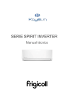
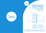
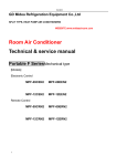
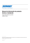
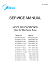
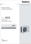
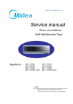
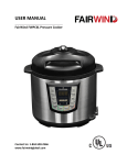
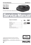
FAIRWIND ON-OFF SERIES Service Manual 2014 12FSEU-A-1405 CONTENTS 1. Precaution .................................................................................................................................................... 3 1.1 Safety Precaution ........................................................................................................................3 1.2 Warning .......................................................................................................................................3 2. Function ........................................................................................................................................................ 7 3. Dimension .................................................................................................................................................... 9 3.1 Indoor Unit ...................................................................................................................................9 3.2 Outdoor Unit ..............................................................................................................................14 4. Refrigerant Cycle Diagram ....................................................................................................................... 16 5. Wiring Diagram .......................................................................................................................................... 18 5.1 Indoor Unit .................................................................................................................................18 5.2 Outdoor Unit ..............................................................................................................................28 6 Installation Details ...................................................................................................................................... 40 6.1 Wrench torque sheet for installation ..........................................................................................40 6.2 Connecting the cables ...............................................................................................................40 6.3 Pipe length and the elevation ....................................................................................................41 6.4 Installation for the first time........................................................................................................44 6.5 Adding the refrigerant after running the system for many years ................................................48 6.6 Re-installation while the indoor unit need to be repaired ...........................................................49 6.7 Re-installation while the outdoor unit need to be repaired .........................................................51 7. Operation Characteristics ......................................................................................................................... 54 8. Electronic function .................................................................................................................................... 55 8.1 Abbreviation ..............................................................................................................................55 8.2 Display function .........................................................................................................................55 8.3 Main Protection .........................................................................................................................56 8.4 Operation Modes and Functions ...............................................................................................57 9. Troubleshooting......................................................................................................................................... 73 9.1 Indoor Unit Error Display ...........................................................................................................73 9.2 Diagnosis and Solution..............................................................................................................74 1. Precaution 1.1 Safety Precaution To prevent injury to the user or other people and property damage, the following instructions must be followed. Incorrect operation due to ignoring instruction will cause harm or damage. Before service the unit, be sure to read this service manual at first. 1.2 Warning Installation Do not use a defective or underrated circuit breaker. Use this appliance on a dedicated circuit. There is risk of fire or electric shock. For electrical work, contact the dealer, seller, a qualified electrician, or an authorized service center. Do not disassemble or repair the product, there is risk of fire or electric shock. Always ground the product. There is risk of fire or electric shock. Install the panel and the cover of control box securely. There is risk of fire of electric shock. Always install a dedicated circuit and breaker. Improper wiring or installation may cause fore or electric shock. Use the correctly rated breaker of fuse. There is risk of fire or electric shock. Do not modify or extend the power cable. There is risk of fire or electric shock. Do not install, remove, or reinstall the unit by yourself (customer). There is risk of fire, electric shock, explosion, or injury. Be caution when unpacking and installing the product. Sharp edges could cause injury, be especially careful of the case edges and the fins on the condenser and evaporator. For installation, always contact the dealer or an authorized service center. Do not install the product on a defective installation stand. Be sure the installation area does not deteriorate with age. If the base collapses, the air conditioner could fall with it, causing property damage, product failure, and personal injury. Do not let the air conditioner run for a long time when the humidity is very high and a door or a window is left open. Take care to ensure that power cable could not be pulled out or damaged during operation. There is risk of fire or electric shock. Do not place anything on the power cable. There is risk of fire or electric shock. Do not plug or unplug the power supply plug during operation. There is risk of fire or electric shock. Do not touch (operation) the product with wet hands. Do not place a heater or other appliance near the power cable. There is risk of fire and electric shock. Do not allow water to run into electrical parts. It may cause fire, failure of the product, or electric shock. Do not store or use flammable gas or combustible near the product. There is risk of fire or failure of product. Do not use the product in a tightly closed space for a long time. Oxygen deficiency could occur. When flammable gas leaks, turn off the gas and open a window for ventilation before turn the product on. If strange sounds or smoke comes from product, turn the breaker off or disconnect the power supply cable. There is risk of electric shock or fire. Stop operation and close the window in storm or hurricane. If possible, remove the product from the window before the hurricane arrives. There is risk of property damage, failure of product, or electric shock. Do not open the inlet grill of the product during operation. (Do not touch the electrostatic filter, if the unit is so equipped.) There is risk of physical injury, electric shock, or product failure. When the product is soaked, contact an authorized service center. There is risk of fire or electric shock. Be caution that water could not enter the product. There is risk of fire, electric shock, or product damage. Ventilate the product from time to time when operating it together with a stove etc. There is risk of fire or electric shock. Turn the main power off when cleaning or maintaining the product. There is risk of electric shock. When the product is not be used for a long time, disconnect the power supply plug or turn off the breaker. There is risk of product damage or failure, or unintended operation. Take care to ensure that nobody could step on or fall onto the outdoor unit. This could result in personal injury and product damage. CAUTION Always check for gas (refrigerant) leakage after installation or repair of product. Low refrigerant levels may cause failure of product. Install the drain hose to ensure that water is drained away properly. A bad connection may cause water leakage. Keep level even when installing the product. It can avoid vibration of water leakage. Do not install the product where the noise or hot air from the outdoor unit could damage the neighborhoods. It may cause a problem for your neighbors. Use two or more people to lift and transport the product. Do not install the product where it will be exposed to sea wind (salt spray) directly. It may cause corrosion on the product. Corrosion, particularly on the condenser and evaporator fins, could cause product malfunction or inefficient operation. Operational Do not expose the skin directly to cool air for long time. (Do not sit in the draft). Do not use the product for special purposes, such as preserving foods, works of art etc. It is a consumer air conditioner, not a precision refrigerant system. There is risk of damage or loss of property. Do not block the inlet or outlet of air flow. Use a soft cloth to clean. Do not use harsh detergents, solvents, etc. There is risk of fire, electric shock, or damage to the plastic parts of the product. Do not touch the metal parts of the product when removing the air filter. They are very sharp. Do not step on or put anything on the product. (outdoor units) Always insert the filter securely. Clean the filter every two weeks or more often if necessary. A dirty filter reduces the efficiency of the air conditioner and could cause product malfunction or damage. Do not insert hands or other objects through air inlet or outlet while the product is operated. Do not drink the water drained from the product. Use a firm stool or ladder when cleaning or maintaining the product. Be careful and avoid personal injury. Replace the all batteries in the remote control with new ones of the same type. Do not mix old and new batteries or different types of batteries. There is risk of fire or explosion. Do not recharge or disassemble the batteries. Do not dispose of batteries in a fire. They may burn of explode. If the liquid from the batteries gets onto your skin or clothes, wash it well with clean water. Do not use the remote of the batteries have leaked. 3. Function Model Indoor Outdoor Power supply Cooling Heating Capacity Input Rated current EER Capacity Input Rated current COP Moisture Removal Max. input consumption Max. current Starting current Model Type Brand Capacity Input Compressor Rated current(RLA) Locked rotor Amp(LRA) Thermal protector Thermal protector position Capacitor Refrigerant oil/oil charge Model Brand Indoor fan motor Input Capacitor Speed(Hi/Mi/Lo) a.Number of rows b.Tube pitch(a)x row pitch(b) c.Fin spacing Indoor coil d.Fin type (code) e.Tube outside dia.and type f.Coil length x height x width g.Number of circuits Indoor air flow (Hi/Mi/Lo) Indoor noise level (Hi/Mi/Lo) Dimension(W*D*H) Indoor unit Packing (W*D*H) Net/Gross weight Model Brand Outdoor fan Input motor Capacitor Speed a.Number of rows b.Tube pitch(a)x row pitch(b) c.Fin spacing Outdoor coil d.Fin type (code) e.Tube outside dia.and type f.Coil length x height x width g.Number of circuits Outdoor air flow Outdoor noise level Dimension(W*D*H) Outdoor unit Packing (W*D*H) Net/Gross weight Refrigerant type Design pressure Liquid side/ Gas side Refrigerant piping Max. refrigerant pipe length Max. difference in level Thermostat type Operation temperature Room Indoor(cooling/ heating) temperature Outdoor(cooling/heating) Ph-V-Hz Btu/h W A W/W Btu/h W A W/W L/h W A A Btu/h W A A uF ml W uF r/min mm mm mm mm m3/h dB(A) mm mm Kg W uF r/min mm mm mm mm m3/h dB(A) mm mm Kg g MPa mm(inch) m m ℃ ℃ ℃ MDSF-07HRN1 MDSF-07HRN1 MDOF-07HN1 220-240V~ 50Hz, 1Ph 7500 685 3,2 3,21 8000 640 3.0 3,66 0.8 1050 5.5 16.1 ASN82V1UDZ ROTARY GMCC 6995/7029 702/735 3.21/3.15 16.1 ----EXTERNAL 25 ESTEL OIL VG74/300 RPG13H Welling 34 1.2 1200 / 950 / 800 1/2 20x11.28 1.2/1.3 Hydrophilic aluminium Φ6,innergroove tube 540x80x11.28+540x180x22.56 2 460/360/300 40/33/30 715x188x250 775x260x324 6.5 / 8.5 YDK24-6F(B) Welling 63 2.5 800 / -- / -1 21x13.37 1.4 Hydrophilic aluminium Φ7,innergroove tube 600x504x13.37 2 1800 55 700x240x540 815x325x580 22 / 24 R410A/520g 4.2/1.5 Φ6.35/Φ9.52(1/4"/3/8") 20 8 Remote Control 17~30 17~32/0~30 18~43/-7~24 MDSF-09HRN1 MDSF-09HRN1 MDOF-09HN1 220-240V~ 50Hz, 1Ph 9000 820 3,8 3,21 9500 770 3.6 3,62 1.0 1200 6.0 21.7 PA103M1C-4DZDE2 ROTARY GMCC 8428/8530 830/860 3.85/3.73 21.7 B160-135-241E EXTERNAL 25 ESTER OIL VG74 350cc RPG13H Welling 34 1.2 1250 / 1000 / 800 1/2 20x11.28 1.2/1.3 Hydrophilic aluminium Φ6,innergroove tube 540x80x11.28+540x180x22.56 2 460/360/300 41/33/29 715x188x250 775x260x324 6.5 / 8.5 YDK24-6T(B) Welling 70 3.0 815 / -- / -1 21x13.37 1.4 Hydrophilic aluminium Φ7,innergroove tube 694x504x13.37 1 1650 55 700x240x540 815x325x580 24.5 / 26.5 R410A/590g 4.2/1.5 Φ6.35/Φ9.52(1/4"/3/8") 20 8 Remote Control 17~30 17~32/0~30 18~43/-7~24 Model Indoor Outdoor Power supply Cooling Heating Capacity Input Rated current EER Capacity Input Rated current COP Moisture Removal Max. input consumption Max. current Starting current Model Type Brand Capacity Input Compressor Rated current(RLA) Locked rotor Amp(LRA) Thermal protector Thermal protector position Capacitor Refrigerant oil/oil charge Model Brand Indoor fan motor Input Capacitor Speed(Hi/Mi/Lo) a.Number of rows b.Tube pitch(a)x row pitch(b) c.Fin spacing Indoor coil d.Fin type (code) e.Tube outside dia.and type f.Coil length x height x width g.Number of circuits Indoor air flow (Hi/Mi/Lo) Indoor noise level (Hi/Mi/Lo) Dimension(W*D*H) Indoor unit Packing (W*D*H) Net/Gross weight Model Brand Outdoor fan Input motor Capacitor Speed a.Number of rows b.Tube pitch(a)x row pitch(b) c.Fin spacing Outdoor coil d.Fin type (code) e.Tube outside dia.and type f.Coil length x height x width g.Number of circuits Outdoor air flow Outdoor noise level Dimension(W*D*H) Outdoor unit Packing (W*D*H) Net/Gross weight Refrigerant type Design pressure Liquid side/ Gas side Refrigerant piping Max. refrigerant pipe length Max. difference in level Thermostat type Operation temperature Room Indoor(cooling/ heating) temperature Outdoor(cooling/heating) Ph-V-Hz Btu/h W A W/W Btu/h W A W/W L/h W A A Btu/h W A A uF ml W uF r/min mm mm mm mm m3/h dB(A) mm mm Kg W uF r/min mm mm mm mm m3/h dB(A) mm mm Kg g MPa mm(inch) m m ℃ ℃ ℃ MDSF-12HRN1 MDSF-12HRN1 MDOF-12HN1 220-240V~ 50Hz, 1Ph 11500 1050 4.5 3.21 12000 975 4.2 3.61 1.1 1800 8.0 25.1 PA130G1C-4FTL ROTARY GMCC 12505/12556 885/920 4.10/3.90 25.1 --INTERNAL 35 ESTER OIL VG74 · 400 ml RPG20E Welling 45 1.5 1200 / 1050 / 800 1/2 21x13.37 1.2 Hydrophilic aluminium Φ7,innergroove tube 621x84x13.37+621x210x26.74 3 580/500/400 40/36/30 800x188x275 865x265x350 8 / 10 YDK36-6 Welling 70 2.5 900 / -- / -1 22x19.05 1.4 Hydrophilic aluminium Φ7.94, innergroove tube 740x506x19.05 2 1800 56 780x250x540 910x335x585 28 / 30 R410A/800g 4.2/1.5 Φ6.35/Φ12.7(1/4"/1/2") 20 8 Remote Control 17~30 17~32/0~30 18~43/-7~24 MDSF-18HRN1 MDSF-18HRN1 MDOF-18HN1 220-240V~ 50Hz, 1Ph 18000 1640 7,6 3,21 19000 1540 7.1 3,62 1.8 2200 12.0 31.8 PA200M2CS-4KU2 ROTARY GMCC 16581 1605 7.45 31.8 ---INTERNAL 45 ESTER OIL VG74 750cc RPG28D Welling 58 1.5 1280/1100/800 2 21x13.37 1.2 Hydrophilic aluminium Φ7,innergroove tube 750x294x26.74 3 800/700/500 45/40/33 940x205x275 1015x265x350 10 / 12.5 YDK48-6H(A) Welling 110 3.0 890 / -- / -2 21x13.37 1.4 Hydrophilic aluminium Φ7,innergroove tube 660x546x26.74 3 2300 60 760x285x590 887x355x645 36.5 / 39 R410A/1150g 4.2/1.5 Φ6.35/Φ12.7(1/4"/1/2") 25 10 Remote Control 17~30 17~32/0~30 18~43/-7~24 Model Indoor Outdoor Power supply Cooling Heating Capacity Input Rated current EER Capacity Input Rated current COP Moisture Removal Max. input consumption Max. current Starting current Model Type Brand Capacity Input Compressor Rated current(RLA) Locked rotor Amp(LRA) Thermal protector Thermal protector position Capacitor Refrigerant oil/oil charge Model Brand Indoor fan motor Input Capacitor Speed(Hi/Mi/Lo) a.Number of rows b.Tube pitch(a)x row pitch(b) c.Fin spacing Indoor coil d.Fin type (code) e.Tube outside dia.and type f.Coil length x height x width g.Number of circuits Indoor air flow (Hi/Mi/Lo) Indoor noise level (Hi/Mi/Lo) Dimension(W*D*H) Indoor unit Packing (W*D*H) Net/Gross weight Model Brand Outdoor fan Input motor Capacitor Speed a.Number of rows b.Tube pitch(a)x row pitch(b) c.Fin spacing Outdoor coil d.Fin type (code) e.Tube outside dia.and type f.Coil length x height x width g.Number of circuits Outdoor air flow Outdoor noise level Dimension(W*D*H) Outdoor unit Packing (W*D*H) Net/Gross weight Refrigerant type Design pressure Liquid side/ Gas side Refrigerant piping Max. refrigerant pipe length Max. difference in level Thermostat type Operation temperature Room Indoor(cooling/ heating) temperature Outdoor(cooling/heating) Ph-V-Hz Btu/h W A W/W Btu/h W A W/W L/h W A A Btu/h W A A uF ml W uF r/min mm mm mm mm m3/h dB(A) mm mm Kg W uF r/min mm mm mm mm m3/h dB(A) mm mm Kg g MPa mm(inch) m m ℃ ℃ ℃ MDSF-24HRN1 MDSF-24HRN1 MDOF-24HN1 220-240V~ 50Hz, 1Ph 24000 2330 10,8 3,02 25000 2140 9,9 3,42 2.6 4000 20.0 60 PA270G2CS-4MU1 ROTARY GMCC 23287/23458 2235/2385 10.55/11.15 60 --INTERNAL 60 ESTER OIL VG74/850 CC RPG45C Welling 77 3.0 1180 / 1100 / 900 2 21x13.37 1.3 Hydrophilic aluminium Φ7,innergroove tube 780x315x26.74 5 1150/1050/900 48/45/41 1045x235x315 1135x395x315 12 / 15 YDK53-6C Welling 136 3.0 800 2 21x13.37 1.4 Hydrophilic aluminium Φ7,innergroove tube 785x651x26.74 4 2700 58 845x320x700 965x395x755 49 / 52 R410A/1690g 4.2/1.5 Φ9.52/Φ15.9(3/8"/5/8") 25 10 Remote Control 17~30 17~32/0~30 18~43/-7~24 3. Dimension 3.1 Indoor Unit H D W Model W D H MS12F-07HRN1-QC2 MS12F-09HRN1-QC2 MS12F-12HRN1-QC2 715 715 800 188 188 188 250 250 275 MS12F-18HRN1-QC2 MS12F-24HRN1-QB8W 940 1045 205 235 275 315 Model MS12F-07HRN1-QC2 L(mm) R(mm) H(mm) MS12F-09HRN1-QC2 MS12F-12HRN1-QC2 85 88 45 100 95 45 MS12F-18HRN1-QC2 110 100 45 MS12F-24HRN1-QB8W 293 163 45 Dimension of installation hole(mm) ¢65 3.2 Outdoor Unit More than 30cm More than 60cm ︶ (Service space More than 30cm Fe n ob c e o sta r cle s More than 60cm More than 200cm Model MOA-07HN1-QC2 MOA3-09HN1-QC2 W 700 700 D 240 240 H 540 540 W1 757 757 A 458 458 B 250 250 MOB-12HN1-QC2 780 250 540 843 549 276 MOC2-18HN1-QC2 760 285 590 823 530 290 MOF-24HN1-QB8W 845 320 700 908 560 335 4. Refrigerant Cycle Diagram For heat pump models: INDOOR OUTDOOR CHECK VALVE (Heating Model only) LIQUID SIDE 2-WAY VALVE CAPILIARY TUBE HEAT EXCHANGE (EVAPORATOR) HEAT EXCHANGE (CONDENSER) T1 Room temp. sensor T2 Evaporator temp. sensor GAS SIDE 4-WAY VALVE 3-WAY VALVE ACCUMULATOR COOLING COMPRESSOR T3 temp. sensor is only for 24 and 28k HEATING 5. Wiring Diagram 5.1 Indoor Unit MS12F-07HRN1-QC2, MS12F-09HRN1-QC2, MS12F-24HRN1-QB8W, MS12F-12HRN1-QC2, MS12F-18HRN1-QC2, 5.2 Outdoor Unit MOA-07HN1-QC2, MOA3-09HN1-QC2, MOB-12HN1-QC2, MOF-24HN1-QB8W, MOC2-18HN1-QC2, 6 Installation Details 6.1 Wrench torque sheet for installation Outside diameter Torque Additional tightening torque mm inch N.cm N.cm Ф6.35 1/4 1500(153kgf.cm) 1600(163kgf.cm) Ф9.52 3/8 2500(255kgf.cm) 2600(265kgf.cm) Ф12.7 1/2 3500(357kgf.cm) 3600(367kgf.cm) Ф15.9 5/8 4500(459kgf.cm) 4700(479kgf.cm) Ф19 3/4 6500(663kgf.cm) 6700(683kgf.cm) 6.2 Connecting the cables The power cord of connect should be selected according to the following specifications sheet. Rated current of appliance Nominal cross-sectional area (mm²) >3 and ≤6 0.75 >6 and ≤10 1 >10 and ≤16 1.5 >16 and ≤25 2.5 The cable size and the current of the fuse or switch are determined by the maximum current indicated on the nameplate which located on the side panel of the unit. Please refer to the nameplate before selecting the cable, fuse and switch. 6.3 Pipe length and the elevation The pipe length and refrigerant amount: Pipe size Model MS12F-07HRN1-QC2+MOA-07HN1-QC2 MS12F-09HRN1-QC2+MOA3-09HN1-QC2 MS12F-12HRN1-QC2+MOB-12HN1-QC2 MS12F-18HRN1-QC2+MOC2-18HN1-QC2 MS12F-24HRN1-QB8W+MOF-24HN1-QB8W Gas Liquid 3/8’’ 1/4’’ (Ф9.52) (Ф6.35) 3/8’’ 1/4’’ (Ф9.52) (Ф6.35) 1/2’’ 1/4’’ (Ф12.7) (Ф6.35) 1/2’’ 1/4’’ (Ф12.7) (Ф6.35) 5/8’’ 3/8’’ (Ф15.9) (Ф9.52) Standard Max. Max. Additional length Elevation Length refrigerant (m) B (m) A (m) (g/m) 5 8 20 20 5 8 20 20 5 8 20 20 5 10 25 20 5 10 25 40 Caution: The capacity test is based on the standard length and the maximum permissive length is based on the system reliability. The oil trap should be installed per 5-7 meters. 7. Operation Characteristics 25 CAUTION: 1. If the air conditioner is used beyond the above conditions, certain safety protection features may come into operation and cause the unit to operate abnormally. 2. The room relative humidity should be less than 80%. If the air conditioner operates beyond this figure, the surface of the air conditioner may attract condensation. Please set the vertical air flow louver to its maximum angle (vertically to the floor), and set HIGH fan mode. 3. The optimum performance will be achieved during this operating temperature zone. 8. Electronic function 8.1 Abbreviation T1: Indoor room temperature T2: Coil temperature of evaporator T3: Coil temperature of condenser T4: Outdoor ambient temperature T5: Compressor discharge temperature 8.3 Main Protection 8.3.1 Time Delay at restart for compressor. 8.3.2 Sensor protection at open circuit and breaking disconnection. 8.3.3 Zero crossing detection error protection If AC can not detect zero crossing signal for 4 minutes or the zero crossing signal time interval is not correct, the unit will stop and the LED will display the failure. The correct zero crossing signal time interval should be between 6-13ms. 8.3.4 Fan Speed is out of control When Indoor Fan Speed is too low(lower than 300RPM) lasting 2 minutes, the unit stops and LED displays failure information and can’t returns to normal operation automatically. 8.3.5 Current protection I3SEC A B I5MIN C IFAN IRESTORE Resume A zone : The current exceeds I3SEC for 5 seconds the compressor and outdoor fan will shut off. B zone: The current exceeds I5min for 5 minutes, the compressor and outdoor fan will shut off. C zone: The current exceeds IFAN, the outdoor fan will shut off if AC is in heating mode. If AC is in cooling mode, the indoor fan will run at low speed. 8.4 Operation Modes and Functions 8.4.1 Fan mode (1) Outdoor fan and compressor stop. (2) Temperature setting function is disabled, and no setting temperature is displayed. (3) Indoor fan can be set to high/med/low/auto. (4) The louver operates the same as in cooling mode. (5) Auto fan: 29 High 28 Medium 25 Low 8.4.2 Cooling Mode 8.4.2.1 Compressor running rules Once the compressor starts up, it will run 5.5 minutes. And then it will follow the below rules: When indoor room temp.T1 is lower than Tn, the compressor and outdoor fan will shut off. When T1 is higher than Tm, the compressor and outdoor fan will start up. Tm=Ts, Tn=Ts-2. 8.4.2.2 Outdoor fan running rules The On-off outdoor units have single fan speed. The outdoor fan will run following the compressor except when AC is in evaporator high temp. protection in heating mode ,condenser high temp. protection in cooling mode, defrosting mode and the current protection. 8.4.2.3 Indoor fan running rules In cooling mode, indoor fan runs all the time and the speed can be selected as high, medium, low and auto. The auto fan: 8.4.2.4 Low evaporator coil temperature T2 protection T2 On TE6 TE5 Off When the evaporator coil temp.T2 keeps lower than TE5 for 5 minutes, the compressor and outdoor fan will shut off. When T2 is higher than TE6, the compressor and outdoor fan will restart up. 8.4.3 Heating Mode 8.4.3.1 Compressor running rules: Once the compressor starts up, it will run 7 minutes. And then it will follow the below rules: When indoor room temp.T1 is higher than Tj, the compressor and outdoor fan will shut off. When T1 is lower than Tk, the compressor and outdoor fan will start up. While Tj=Ts+TB; Tk=Ts+TB-2 8.4.3.2 Outdoor fan running rules: The outdoor units have single fan speed. The outdoor fan will run following the compressor except when AC is in evaporator high temp. protection in heating mode , condenser high temp. protection in cooling mode ,defrosting mode and the current protection. 8.4.3.3 Indoor fan running rules: Auto fan action: When T1-Ts>2℃, the indoor fan will run at low speed. When T1-Ts≤0℃, the indoor fan will run at medium speed. 8.4.3.4 Defrosting mode: For 7, 9, 12 and 18k, Condition of defrosting: 1, AC will enter the defrosting mode if all of the following items(1.1,1.2,1.3 or 1.1, 1.2, 1.4) are satisfied. ∆T′=∆T, if the indoor fan=low speed. ∆T′=∆T+3, if the indoor fan=medium speed. ∆T′=∆T+5, if the indoor fan=high speed. ∆T′max is the maximum value of ∆T′. When fan speed changes( including anti-cold wind function), AC will detect ∆T after two minutes. 1.1 AC meets A1 or A2. A1: The cumulative compressor running time is between 45~120 minutes. Meanwhile the value of ∆T meets the below table. ℃ ∆T High speed <THDEFROST Medium speed <TMDEFROST Low speed <TLDEFROST A2: The cumulative compressor running time is over 120 minutes. Meanwhile the value of ∆T meets the below table. ℃ ∆T High speed <THDEFROST+2 Medium speed <TMDEFROST+2 Low speed <TLDEFROST+2 1.2 If the fan speed and the evaporator coil temp.T2 meet the below issues: ℃ T2 High speed <43℃ Medium speed <46℃ Low speed <48℃ 1.3 After the compressor keeps running 8 minutes, ∆T′ max-∆T′ ≥6℃(∆T=T2-T1) 1.4 After the compressor keeps running 8 minutes, if -5℃<T1<45℃ and -5℃<T2<45℃, AC will detect the △T. Mark the time of ∆T′ dropped 1.5 degree as t. When 1min<t< FALL08CTM, this condition is satisfied.(FALL08CTM is controlled by EEPROM chip). About the setting defrosting time: runtime(minute) Defrosting time(minute) Case 1 Runtime=45 10 Case 2 45<runtime≤60 7.5 Case 3 60<runtime≤90 8.5 Case 4 90<runtime≤120 10 Case 5 120<runtime 12 2, AC will enter the defrosting mode if all of the following items are satisfied: 2.1 The compressor cumulative running time is over 45 minutes. 2.2 The compressor continuous running time is over 8 minutes. 2.3 The indoor fan is off. In this case, the defrosting time is ten minutes. 3, AC will enter the defrosting mode if all of the following items are satisfied: 3.1 After AC runs in heating mode, there is no defrosting before. 3.2 The cumulative compressor running time is over 45 minutes. 3.3 The 1.1 and 1.2 are satisfied if AC is in high/Medium/Low speed .Or the fan speed is breeze. In this case, the defrosting time is ten minutes. a) Condition of ending defrosting: If any one of the following items is satisfied, the defrosting will terminate and the machine will turn to normal heating mode. (1) The defrosting time is reached to the setting value. (2) The defrosting has been running for 3 minutes and T2≥2℃. (3) The defrosting has been running for 2 minutes, check the value of T2. If T2-T2min≥2℃ during 4 minutes, the defrosting will terminate. (4) The compressor current has reached to IDEFROST or above lasting 7 seconds, IDEFROST differs in different models Defrosting action: Compressor 4-way valve Outdoor fan Indoor fan on off on off on off on off Indoor fan breeze(10s) DF-5 DF DF-5 F8 DF Setting defrosting time For 24k Condition of defrosting: AC will enter defrosting mode if any of the following items is satisfied. (1) If T3<TC1 and the compressor keeps running over 45 minutes. Meanwhile T3<TC3 for 3minutes (2) After the last defrosting, the time that the outdoor fan is off but the compressor is on in high T2 protection cumulates up to 90 minutes. Condition of ending defrosting: If any one of the following items is satisfied, the defrosting will terminate and the machine will turn to normal heating mode. (1) T3 rises to be higher than TC2. (2) The machine has run for 10 minutes in defrosting. Defrosting action: 8.4.3.5 High evaporator coil temp.T2 protection: 8.4.4 Auto-mode This mode can be chosen with remote controller and the setting temperature can be changed between 17~30℃. In auto mode, the machine will choose cooling, heating or fan-only mode according to ∆T (∆T =T1-Ts). ∆T=T1-Ts Running mode ∆T>2℃ Cooling -3≤∆T≤2℃ Fan-only ∆T<-3℃ Heating(For cooling only models, they will run at fan speed) AC will run in auto mode in the below cases: (1) Pressing the forced auto button. (2) If AC is off, it will run in auto mode when the timer on function is active. (3) After setting the mode, AC will run in auto mode if the compressor keeps not running for 20 minutes. 8.4.5 Drying mode 8.4.5.1 The compressor is cycled running with 10 minutes on and then 5 minutes off. The indoor fan will keep running at low speed. 8.4.5.2 In drying mode, if room temperature is lower than 10℃, the compressor will stop and not resume until room temperature exceeds 13℃. 8.4.5.3 The evaporator anti-freezing protection is the same as that in cooling mode. 8.4.6 Forced operation function Press the touch button continually, the AC will run as below sequence: Forced auto →Forced cooling →Off Forced cooling mode: The compressor and outdoor fan keep running and the indoor fan runs at low speed. After running for 30 minutes, AC will turn to auto mode with 24℃ setting temperature. Forced auto mode: The action of forced auto mode is the same as normal auto mode with 24℃ setting temperature. When AC receives signals, such as switch on, switch off, timer on, timer off, mode setting, fan speed setting, sleeping mode setting, follow me setting, it will quit the forced operation. The forced operation function can not be memorized if power off. 8.4.7 Timer function 8.4.7.1 Timing range is 24 hours. 8.4.7.2 Timer on. The machine will turn on automatically when reaching the setting time. 8.4.7.3 Timer off. The machine will turn off automatically when reaching the setting time. 8.4.7.4 Timer on/off. The machine will turn on automatically when reaching the setting “on” time, and then turn off automatically when reaching the setting “off” time. 8.4.7.5 Timer off/on. The machine will turn off automatically when reaching the setting “off” time, and then turn on automatically when reaching the setting “on” time. 8.4.7.6 The timer function will not change the AC current operation mode. Suppose AC is off now, it will not start up firstly after setting the “timer off” function. And when reaching the setting time, the timer LED will be off and the AC running mode has not been changed. 8.4.7.7 The setting time is relative time. 8.4.7.8 The AC will quit the timer function when it has malfunction. 8.4.8 Sleep function mode 8.4.8.1 Operation time in sleep mode is 7 hours. After 7 hours the AC quits this mode and turns off. 8.4.8.2. Operation process in sleep mode is as follow: When cooling, the setting temperature rises 1℃ (be lower than 30℃) every one hour, 2 hours later the setting temperature stops rising and indoor fan is fixed as low speed. When heating, the setting temperature decreases 1℃ (be higher than 17℃) every one hour, 2 hours later the setting temperature stops rising and indoor fan is fixed as low speed. (Anti-cold wind function has the priority) 8.4.8.3 Timer setting is available 8.4.8.4 When user uses timer off function in sleep mode (or sleep function in timer off mode), if the timing is less than 7 hours, sleep function will be cancelled when reaching the setting time. If the timing is more than 7 hours, the machine will not stop until reaches the setting time in sleep mode. 8.4.9 Auto-Restart function The indoor unit is equipped with auto-restart function, which is carried out through an auto-restart module. In case of a sudden power failure, the module memorizes the setting conditions before the power failure. The unit will resume the previous operation setting (not including swing function) automatically after 3 minutes when power returns. If the memorization condition is forced cooling mode, the unit will run in cooling mode for 30 minutes and turn to auto mode as 24℃ setting temp. If AC is off before power off and AC is required to start up now, the compressor will have 1 minute delay when power on. Other conditions, the compressor will have 3 minutes delay when restarts. 8.4.10 Refrigerant Leakage Detection With this new technology, the display area will show “EC” when the outdoor unit detects refrigerant leakage. 8.4.11 Louver Position Memory Function When starting the unit again after shutting down, its louver will restore to the angle originally set by the user, but the precondition is that the angle must be within the allowable range, if it exceeds, it will memorize the maximum angle of the louver. During operation, if the power fails or the end user shuts down the unit in the turbo mode, the louver will restore to the default angle. 8.4.12 8℃ Heating(optional) In heating operation, the preset temperature of the air conditioner can be as lower as 8℃, which keeps the room temperature steady at 8℃ and prevents household things freezing when the house is unoccupied for a long time in severe cold weather. 9. Troubleshooting 9.1 Indoor Unit Error Display Operation lamp Timer lamp Display ☆ 1 time X E1 LED STATUS EEPROM parameter error Zero-crossing signal detection error(except ☆ 2 times X E2 ☆ 3 times X E3 Indoor fan speed has been out of control ☆ 5 times X E5 Indoor room temperature sensor T1 open circuit or short circuit ☆ 6 times X E6 Evaporator coil temperature sensor T2 open circuit or short circuit ☆ 7 times X E7 ☆ 2 times O EC ☆ 8 times X E8 Condenser coil temperature sensor T3 open circuit or short circuit(only for 24/28k) Refrigerant Leakage Detection Indoor / outdoor units communication error(only for 24/28k) ☆ 9 times X E9 O(light) X(off) ☆(flash) 9.2 Diagnosis and Solution 9.2.1 EEPROM parameter error diagnosis and solution EEPROM: a read-only memory whose contents can be erased and reprogrammed using a pulsed voltage. 9.2.2 Zero crossing detection error diagnosis and solution 9.2.3 Indoor fan speed has been out of control diagnosis and solution Index 1: 1:Indoor AC Fan Motor Measure the resistance value of each winding by using the tester. For the resistance value of the motor, please contact the technical engineer. Index2: 1: Indoor AC Fan Motor Power on and set the unit running in fan mode at high fan speed. After running for 15 seconds, measure the voltage of pin1 and pin2. If the value of the voltage is less than 100V(208~240V power supply)or 50V(115V power supply), the PCB must has problems and need to be replaced. 9.2.4 Open circuit or short circuit of temperature sensors diagnosis and solution 9.2.5 Refrigerant Leakage Detection diagnosis and solution Shut off the power supply and turn it on 5 seconds later. Is it still displaying the error code? Yes Is there cool air blowing out from indoor air outlet? Yes No Yes Is there any leakage? Especially the connection parts, such as the gas valve and the liquid valve. No Replace indoor PCB. Yes Is there any block i n g ? (Such as the capillary or the welded points of the pipes.) Yes Clear the blocking. Check if T2 sensor is well fixed. Correct the installation or replace T2 sensor. Does the problem remain again? Repair the leakage and recharge the refrigerant. 9.2.6 Indoor / outdoor units communication error diagnosis and solution Main parts check 1.Temperature sensor checking Disconnect the temperature sensor from PCB, measure the resistance value with a tester. Temperature Sensors. Room temp.(T1) sensor, Indoor coil temp.(T2) sensor, Outdoor coil temp.(T3) sensor, Outdoor ambient temp.(T4) sensor, Compressor discharge temp.(T5) sensor. Measure the resistance value of each winding by using the multi-meter. Table1:Some frequently-used R-T data for T1,T2,T3 and T4 sensor: Temperature (℃) 5 10 15 20 25 30 40 50 60 Resistance Value (KΩ) 26.9 20.7 16.1 12.6 10 8 5.2 3.5 2.4 Table2:Some frequently-used R-T data for T5 sensor: Temperature (℃) 5 15 25 35 60 70 80 90 100 Resistance Value (KΩ) 141.6 88 56.1 36.6 13.8 9.7 6.9 5 3.7 Resistance value (KΩ) T5 T1,T2,T3,T4 Temperature (℃)