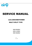
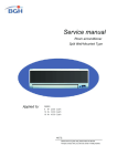
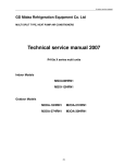
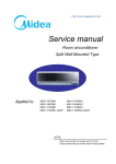
1
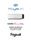
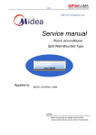
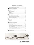
Service Manual Multi Split Type Heat Pump Air Conditioners Applied to: DS-9U2M_DOS-18U2M DS-9U11M_DS-12U11M_DOS-21U11M Content Content Multi SERIES 1. Features 2. Specification 3. Dimensions 4. Refrigeration cycle diagram 5. Operation limits 6. Wiring diagram 7. Troubleshooting 8. Electronic function 9. Exploded view parts 10. Characteristic of temp. sensor Service manual 1.Features 1.1 Compact design 1.2 High efficiency and quiet operation 1.3 Universal outdoor unit and indoor unit design -1- Service manual 2 Specifications 2.1 Indoor unit Glory multi indoor unit DS-9U2M_DOS-18U2M DS-9U11M_DS-12U11M_DOS-21U11M MSGI-09HRN1 MSGI-12HRN1 Model Power supply Indoor motor fan Ph-V-Hz 1Ph,220-240V~,50Hz 1Ph,220-240V~,50Hz Model RPG13H RPG13H Brand Welling Welling Input W 36.5 36.5 Capacitor uF 1.2F/450V 1.2F/450V 1180/1080/1000 1250/1100/950 2 2 mm 21X13.37 21X13.37 mm 1.3 1.3 Hydrophilic aluminum Hydrophilic aluminum Speed(hi/mi/lo) r/min a.Number of rows b.Tube pitch(a)x row pitch(b) Indoor coil c.Fin spacing d.Fin type (code) e.Tube outside dia.and type mm Ï7, Inner groove tube Ï7, Inner groove tube f.Coil length x height x width mm 578X252X26.74 578X252X26.74 2 2 m3/h 510/460/410 660/580/500 dB(A) 36/34/32 39/33/28 g.Number of circuits Indoor air flow (Hi/Mi/Lo) Indoor noise level (Hi/Mi/Lo) Indoor unit Dimension (W*H*D) mm 750×250×188 815×280×195 Packing mm 830X336X280 915X360X275 Kg 8.5/10.5 10.5/13.5 (W*H*D) Net/Gross weight -2- Service manual 2.2 Outdoor unit Model Power supply Ph-V-Hz Capacity M2OA-21HRN1 DS-9U11M_DS-12U11M_DOS-21U11M 1Ph,220-240V~,50Hz 1Ph,220-240V~,50Hz Hz HzHz 18000 20000 W 1861 2150 A 8.3 9.5 Btu/w.h 9.7 9.3 19000 21500 W 1900 2194 A 8.4 9.7 Btu/w.h 10.0 9.8 L/h 1.0x2 +1.2 1.0x2 +1.2 W 2160 2580 Max. current A 9.9 11.7 Starting current A 21.7 Cooling Btu/h M2OA-18HRN1 DS-9U2M_DOS-18U2M Input Rated current EER Capacity Heating Btu/h Input Rated current COP Moisture Removal Max. input consumption Compressor 29.9 PA108X1C-4FT; Model PA108X1C-4FTx2 Type Rotary Rotary Brand GD Toshiba GD Toshiba 8874 8874/12014 W 890 890/1200 A 4.07 4.07/5.6 A 40 40/57 Internal Internal Capacity Btu/h Input Rated current(RLA) Locked rotor Amp(LRA) Thermal protector Capacitor uF 25uF/440-450VACx2 PA145X2C-4FT 25uF/440VAC; 35uF/440VAC -3- Service manual Refrigerant oil Outdoor fan motor ml 350 350/480 Model YDK60-6 YDK60-6 Brand Welling Welling Input W 122 122 Capacitor uF 4uFx2 4uFx2 830/650 830/650 2 2 mm 25.4x24 25.4x24 mm 1.7 1.7 Hydrophilic aluminium Hydrophilic aluminium Speed r/min a.Number of rows b.Tube pitch(a)x row pitch(b) c.Fin spacing d.Fin Outdoor coil type (code) e.Tube mm outside Ï9.53, Innergroove tube dia.and type f.Coil length x height x width mm 810X610X44 810X610X44 2/2 2/2 m3/h 2200 2200 dB(A) 56 56 mm 895X655X345 895X655X345 mm 1050X720X470 1050X720X470 75/81 76/82 R410A/ 980x2 R410A/ 1100+900 4.2/2.5 4.2/2.5 g.Number of circuits Outdoor air flow Outdoor noise level Dimension(W *H*D) Outdoor unit Packing (W*H*D) Net/Gross weight Refrigerant type Kg g Design pressure(Hi/Lo) Liquid MPa side/ Gas side Ï9.53, Innergroove tube mm(inch) Ï6.35/Ï9.53 Ï6.35/Ï9.53; Ï6.35/Ï12.7 Max. Refrigerant refrigerant piping pipe length m 10 (each unit) 10 (each unit) m 10 (each unit) 10 (each unit) Max. difference in level Connection wiring No No Plug type No No Thermostat type Electronic control Electronic control 17~30 17~30 18~45(cooling); 18~45(cooling); -7~30(heating) -7~30(heating) (14-21)x2,16-24 (14-21)x2,16-24 Operation temp ć Ambient temp ć Application area m2 -4- Service manual 3.Dimensions 3.1 Indoor unit a) Indoor unit 9K b) IndoorUnit12K -5- Service manual 3.2 Outdoor unit a) Outdoor unit 18K/21K -6- Service manual 4.Refrigeration cycle diagram “1 drive 3 system” is made up of one “1 drive 1 system” and one “1 drive 2 system”. PMV1 PMV2 SV2 SV1 T2 2ʿ 1ʿ T1 Compressor refrigeration distributor 1 drive 2 system SV1˖Primary four-way valve SV2˖ Secondary four-way valve T1ˈT2˖Indoor pipe temperature sensor PMV1ˈ PMV2˖Electronic expansive valve Condenser Four-way valve Evaporator Compressor 1 drive 1 system Notice˖For 1 drives 2 system, there are two individual refrigerant circuit and two compressors, but for the 1drive 2 system in the 1 drive three system, there is only one refrigerant circuit and only one compressor. -7- Service manual 5.Operation limits 5.1Cooling operation Outdoor unit air temp.ć DB 45 COOLING 17 -7 0 15 Indoor air temp. ć DB 32 Note: 1.The chart is the result from the continuous operation under constant air temperature Condition. However, excludes the initial pull-down stage. 2.The operation range below the dashed is the result added the low ambient kit. 5.2Heating operation Indoor air temp. ć DB 30 25 20 15 10 5 -5 5 15 25 Outdoor unit air temp.ć DB Note : The chart is the result from the continuous operation under constant air temperature conditions. However, excludes the initial pull-down stage. -8- Service manual 6.Wiring diagram Indoor unit˄9k/12k˅ Glory indoor unit -9- Service manual Outdoor unit For 1 drive 2 outdoor unit(18/21k) -10- Service manual 7.Troubleshooting 7.1 Indoor unit Failure phenomenon Operation lamp Timer lamp ƿ X ƿ on EEPROM error on ƿ Over current protection of the compressor occurs 4 times in 1h X ƿ Indoor fan speed has been out of control for over 1 minute Indoor room temp. sensor or evaporator temp. sensor is open circuit or short circuit Extinguish ƿ Flash at 5Hz On Light 7.2 Outdoor unit Failure phenomenon Stand by LED1 LED2 LED3 ƿ ƿ ƿ ƿ ƿ High temp. protect of condenser Temp. sensor in condenser 1 is open circuit or short circuit Temp. sensor in condenser 2 is open circuit or short circuit ƿ ƿ ƿ Flash at 2Hz -11- Service manual 8 Electronic functions 8.1 Electric Control working environment 8.1.1 Input voltage: 165~253V 8.1.2 Input power frequency: 50Hz/60Hz 8.1.3 Ambient temperature: -7qC~+43qC 8.1.4 Indoor fan normal working amp is less than 1A, 8.1.5 Outdoors fan. Normal working amp is less than 1A 8.1.6 Four-way valve normal working amp is less than 0.5A. 8.1.7 Swing motor: DC12V. 8.2 Proper symbols and their meanings TA: Indoor ambient temperature TE: Indoor evaporator temperature TS: Setting temperature through the remote controller TE1: Anti-cold wind, from Fan Off to Breeze temperature TE2: Anti-cold wind, from Breeze to Setting Fan Speed temperature TE3: Anti-cold wind, from Setting Fan Speed to Breeze temperature TE4: Anti-cold wind, from Breeze to Fan Off temperature TE5: Evaporator low temperature protection entering temperature TE6: Evaporator low temperature protection restoring temperature TE7: Evaporator high temperature protection, compressor off temperature TE8: Evaporator high temperature protection, fan off temperature TE9: Evaporator high temperature protection, restoring temperature T3: Outdoor unit pipe sensor T4: Outdoor temperature sensor 8.3 Systematic functions. Remote receiving. Testing and forced run. Position set for indoor unit wind vane. LED displaying and alarm. On or off Timer. Protection for the compressor. High temperature protection of indoor heat exchanger in heating mode. Auto defrosting and heating recovery under heating mode. Anti cold air under heating mode. Anti frozen under cooling mode. -12- Service manual 8.5 8.5.1 8.5.2 8.5.3 8.5.4 8.5.5 Protection The compressor functions protection with a delay of three minutes. High temp. protection of condenser. Sensor protection at open circuit and breaking disconnection Temperature Fuse break protection Fan Speed is out of control. When Indoor Fan Speed is too high(higher than High Fan+300RPM)or too low(lower than 400RPM), the entire unit stops and LED displays failure information and can’t returns to normal operation automatically. 8.6 Fan-only mode Fan speed is high/mid/low/ Auto 8.7 Cooling mode The 4-way valve is closed under cooling mode. The action of the compressor and the outdoor fan: Condition Temp. up Compressor TA> Ts+1 Temp. down Outdoor fan On On TA<Ts+1 Off Off TA> Ts On On TA<Ts Off Off TA: Indoor ambient temperature TS: Setting temperature through the remote controller Auto fan under cooling mode: Condition Indoor fan speed T=Indoor Temp.-Setting Temp. Temp. up Temp. down T<3ć Low 3ć<T<5ć Med. T>5ć High T> 3ć High 1ć<T<3ć Med. T<1ć Low Anti-freezing control to indoor evaporator under cooling mode Condition Temp. Temp. up >5 Minutes T> TE5 T< TE5 Outdoor fan Time T> TE6 T< TE6 Temp. down Compressor >5 Minutes On On Off Off On On Off Off Condenser high-temperature protection under heating mode T3 >65ć, turn off compressor. TE5: Evaporator low temperature protection entering temperature TE6: Evaporator low temperature protection restoring temperature 8.8 Dehumidifying mode 8.8.1 The 4-way valve is off in dehumidifying mode 8.8.2 Compressor and Indoor Fan actions in dehumidifying mode Compressor run 5 minutes , and indoor fan run 5 minutes in low speed, then turn off the -13- Service manual 8.8.3 8.8.4 8.9 8.9.1 8.9.2 8.9.3 compressor, indoor fan run 5 minutes in low speed. And repeat on and off cycle. Low room temperature protection: When room temperature decreases to below 10ć, the compressor and the outdoor fan will stop(indoor fan is Breeze). Dehumidifying operation will be resumed when room temperature restores to over 13ć. Under dehumidifying mode, the anti-freezing function of the indoor heat exchanger is the same as that of cooling mode. Heating mode Generally, the 4-way valve is open in heating mode, but it is closed in defrosting mode. 4-way valve must delay 2 minutes compared with compressor if the compressor changed into non-heating mode or turned off. 4-way valve doesn't delay in dehumidifying mode. Generally, the outdoor fan is turned off with the on-off action of compressor in heating mode, except for the defrosting mode or the end of defrost. Action conditions of compressor under heating mode: compressor must run for 7 minutes after starting and then judge temperature. Meanwhile other protections are still valid. Condition Room temp. up Room temp. down Compressor Outdoor fan TA> Ts+3 Off Off TA<Ts+3 On On TA< Ts+2 On On TA>Ts+2 Off Off TA: Indoor ambient temperature TS: Setting temperature through the remote controller 8.9.4 Indoor Fan actions under heating mode Indoor Fan can be set at HIGH/MID/LOW/AUTO by using a remote controller, but Anti-cold wind function has the priority. Anti-cold wind control function under heating mode Condition Indoor fan speed TE Indoor exchanger temp. up Indoor exchanger temp. down TE<TE1 Off TE1<TE<TE2 Breeze TE>TE2 Setting fan speed TE> TE3 Setting fan speed TE3<TE<TE4 Breeze TE<TE4 Off TE: Indoor evaporator temperature TE1: Anti-cold wind, from Fan Off to Breeze temperature TE2: Anti-cold wind, from Breeze to Setting Fan Speed temperature TE3: Anti-cold wind, from Setting Fan Speed to Breeze temperature TE4: Anti-cold wind, from Breeze to Fan Off temperature -14- Service manual 8.9.5 Auto wind under heating mode Condition Indoor fan speed T=Indoor Temp.-Setting Temp. Room temp. up Room temp. down T<2ć High T>2ć Med. T> 0ć Med. T<0ć High 8.9.6 Indoor evaporator high-temperature protection under heating mode Indoor exchanger temp. up Indoor exchanger temp. down Condition Compressor Outdoor fan TE<TE8 On On TE8<TE<TE7 On Off TE>TE7 Off Off TE>TE9 Off Off TE<TE9 On On TE: Indoor evaporator temperature TE7: Evaporator high temperature protection, compressor off temperature TE8: Evaporator high temperature protection, fan off temperature TE9: Evaporator high temperature protection, restoring temperature 8.10 Defrosting operation (Available for heating only). 8.10.1 Defrosting condition: When T3<0ć and compressor runs 40 minutes. T3: Temp. of condenser. 8.10.2 Ending condition of defrost If one of following conditions is satisfied, end the defrost and turn into heating: A.The defrost time has reached to 10 minutes. B.T3>20. ć 8.10.3 Time sequence of the whole defrosting procedure is as follows Compressor ON 4-way Valve ON OFF Outdoor Fan ON OFF -15- Service manual 8.11 Automatic operation mode 8.11.1 The air conditioner automatically selects one of the following operation modes: cooling, heating or ventilation according to the difference between room temp. (TA) and set temp. (TS). TA—TS Operation mode TA—TS>2ć Cooling -1ć≤TA—TS≤+2ć Fan-only TA—TS<-1ć Heating (Fan-only for cooling only type) 8.11.2 The indoor fan blows automatically in corresponding selected mode. 8.11.3 The motion of indoor fan’s vane should accord with the selected operation mode. 8.11.4 One mode should be carried out for at least 15 minutes once selected. If the compressor cannot start for 15 minutes, reselect the operation mode according to the room temp. and set temp.or reselect when the set temp. varies. 8.12 Forced cooling function 8.12.1 Select forced cooling function with the forced cooling button or the switch. 8.12.2 The compressor is unconditionally turned on, after 30 minutes cooling operation whose fan mode is set as low, the A/C operates under the DRY mode with a set temp. of 24ć. 8.12.3 All protections of remote control cooling are available under forced cooling operation. 8.13 Forced Auto function Select forced auto function with the forced auto button or the switch in the display board. In forced auto status the A/C operates under remote control mode with a set temp. of 24ć. 8.14 Timer Function Requirement The maximum length of timer is 24 hours and the minimum resolving power is 15 minutes. 8.15 Economic Running 8.15.1 The economic running function is available under cooling, heating or auto mode. 8.15.2 Cooling: The set temperature rise 1ć per hour. Two hours later, the set temperature will maintain as a constant and the air circulation is kept at low speed. 8.15.3 Heating: The set temperature decrease 1ć per hour. Two hours later, the set temperature will maintain as a constant and the air circulation is kept at low speed (Cold air proof function takes precedence over all). 8.15.4 Auto: The economic running function operates in accordance with the selected running mode by the auto mode. -16- Service manual 8.16 Outdoor fan motor Outdoor fan motor has only one speed, it acts like this: when any indoor unit send fan start signal and no mode conflict, outdoor fan starts. When mode conflict happens, only indoor unit with 4-way valve start indoor unit gain fan speed. Evaporator high temperature protection in heating mode: regardless A or B system sends fan motor off requirement, outdoor fan must response. When shut down, outdoor fan delays to stop by 30 seconds. T4: Outdoor temp. Cooling mode Heating mode T4 Outdoor fan motor T4>27ć High speed T4<25ć Low speed T4>13ć Low speed T4<11ć High speed 8.17 Models and Parameters (Indoor ) unit) ) ) ) Model ) ) DS-9U11M_DS-12U11M DS-9U2M_DOS-18U2M MSGI-09HRN1 RN1 RN1 RN1 RN1 RN1 RN1 _DOS-21U11M HSPEEDH 1250 HSPEEDM 1100 HSPEEDL 950 CSPEEDH 1250 CSPEEDM 1100 CSPEEDL 950 CSPEEDS TE1 TE2 TE3 32 32 TE4 TE5 TE6 TE7 60 60 TE8 53 53 TE9 50 50 HSPEEDS -17- Service manual 10. Characteristic of temp. sensor Temp.ć Resistance KΩ Temp.ć Resistance KΩ Temp.ć Resistance KΩ -10 62.2756 17 14.6181 44 4.3874 -9 58.7079 18 13.918 45 4.2126 -8 56.3694 19 13.2631 46 4.0459 -7 52.2438 20 12.6431 47 3.8867 -6 49.3161 21 12.0561 48 3.7348 -5 46.5725 22 11.5 49 3.5896 -4 44 23 10.9731 50 3.451 -3 41.5878 24 10.4736 51 3.3185 -2 39.8239 25 10 52 3.1918 -1 37.1988 26 9.5507 53 3.0707 0 35.2024 27 9.1245 54 2.959 1 33.3269 28 8.7198 55 2.8442 2 31.5635 29 8.3357 56 2.7382 3 29.9058 30 7.9708 57 2.6368 4 28.3459 31 7.6241 58 2.5397 5 26.8778 32 7.2946 59 2.4468 6 25.4954 33 6.9814 60 2.3577 7 24.1932 34 6.6835 61 2.2725 8 22.5662 35 6.4002 62 2.1907 9 21.8094 36 6.1306 63 2.1124 10 20.7184 37 5.8736 64 2.0373 11 19.6891 38 5.6296 65 1.9653 12 18.7177 39 5.3969 66 1.8963 13 17.8005 40 5.1752 67 1.830 14 16.9341 41 4.9639 68 1.7665 15 16.1156 42 4.7625 69 1.7055 16 15.3418 43 4.5705 70 1.6469 -18-