1
SERVICE
This section provides procedures for testing and
replacing various major components used in these
stands should service become necessary. Refer to
Troubleshooting for assistance in determining the
cause of any problem.
WARNING - Inspection, testing, and repair of electrical equipment should be performed only by qualified
service personnel. The stands should be unplugged
when servicing, except when electrical tests are required and the test procedure specifically states to
connect the stand to the power source.
COMPONENT ACCESS
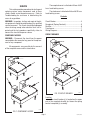
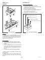
The receptacle cover is attached with four #6-32
truss head locking screws.
The stand cover is attached with four #6-32 truss
head locking screws.
Contents
Circuit Breaker......................................................... 4
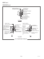
Receptacle (Spring Contacts)................................... 5
Rectifier................................................................... 6
Transformer............................................................. 7
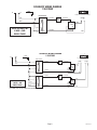
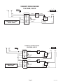
Wiring Diagrams...................................................... 9
CIRCUIT BREAKER
WARNING - Disconnect the stand from the power
source before the removal of any panel or the replacement of any component.
All components are accessible by the removal
of the receptacle cover and the stand cover.
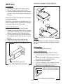
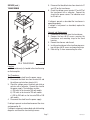
FIG. 2 CIRCUIT BREAKER
P1402
Location
The circuit breaker(s) is located on the upper
part of the receptacle bracket just above the spring
contact receptacle(s) assembly.
FIG. 1 COMPONENT ACCESS
P1402
Page 28342 091597