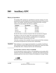
1
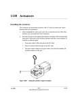
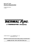
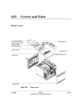
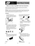
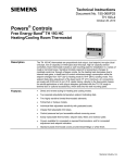
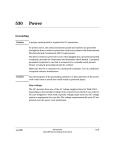
1120 Valve Box
Installing the valve box
The valve box sits on top of the 6890 GC and contains the valves and plumbing,
heated zones and sensors, and the insulation.
1.
WARNING
Use a pair of diagonal cutters to remove the metal cutout on the top of
the GC.
Be careful of sharp edges!
Cut toward the outside edge of the tabs so that the valve box will fit
correctly.
Figure 1120-1
Jun 2001
Removing the sheet metal cutout
Valves
Agilent 6890 Gas Chromatograph Service Manual
1 of 10
1120
Valve Box
Installing the valve box
2.
Screw the aluminum standoffs into the valve box bottom plate using one
Torx T-20 screw for each standoff.
Figure 1120-2
3.
Screw the valve box bottom plate onto the top of the GC using three Torx
T-20 screws.
Figure 1120-3
2 of 10
Attaching the standoffs to the bottom plate
Attaching the bottom plate to the 6890 GC
Valves
Agilent 6890 Gas Chromatograph Service Manual
Jun 2001
Valve Box
Installing the valve box
Note
4.
There are six holes in the plate for up to four valves. The outside holes
on each side of the plate are for valves and the inside holes are for
plumbing into the GC. Punch out the pre-perforated insulation from the
holes you plan to use.
5.
Use two Torx T-20 screws to mount the heater block(s) on the valve box
bottom plate.
6.
Install the heater/sensor into the heater block(s) and secure the leads to
the valve box bottom plate with the U-clamp and two Torx T-10 screws.
Make sure that the sensor is seated all the way in the heater block.
Figure 1120-4
Jun 2001
1120
Attaching heater block to the bottom plate
Valves
Agilent 6890 Gas Chromatograph Service Manual
3 of 10
1120
Valve Box
Installing the valve box
7.
Insert the valve(s) into the appropriate hole(s) in the heater block and
secure each valve with two long Torx T-10 screws.
Figure 1120-5
4 of 10
Installing valves
8.
Plumb the valves in the appropriate configuration. A variety of valve
configurations are diagrammed in the Typical Valve Configurations
section in this chapter.
9.
Orient all of the valves in the OFF (CCW) position.
Valves
Agilent 6890 Gas Chromatograph Service Manual
Jun 2001
Valve Box
Installing the valve box
1120
CCW
Stop
OFF
Figure 1120-6
Valve in the OFF position (top view)
10. Place the valve box insulation in the valve box top. Make sure the
perforations in the insulation line up properly with the valve box top.
11. Insert the insulation retainer plate in the bottom of the valve box top and
secure it to the threaded studs using the two 5.5-mm nuts.
Tighten the nuts until they are flush with the top of the stud. Make sure
the holes in the retainer plate line up with the perforations in the
insulation.
Jun 2001
Valves
Agilent 6890 Gas Chromatograph Service Manual
5 of 10
1120
Valve Box
Installing the valve box
Valve box top
Insulation
Retainer plate
Figure 1120-7
Assembling the valve box top
12. While wearing a pair of protective gloves and holding the valve box top
over a waste receptacle, punch or cut out the insulation from the
appropriate holes.
13. Use two Torx T-20 screws to secure the valve box top over the installed
valves, making sure the heater/sensor leads are routed under the
appropriate cutout(s).
Make sure the valve box top is oriented correctly with holes punched out
over the installed valves.
6 of 10
Valves
Agilent 6890 Gas Chromatograph Service Manual
Jun 2001
Valve Box
Installing the valve box
Figure 1120-8
1120
Installing the valve box top assembly
14. Install the actuators as described in the Actuators section of this chapter.
Jun 2001
Valves
Agilent 6890 Gas Chromatograph Service Manual
7 of 10
1120
Valve Box
Removing the valve box assembly
Removing the valve box assembly
1.
WARNING
Place the main power switch in the off position.
Hazardous voltages are present in the instrument when the power cord is
connected. Avoid a potentially dangerous shock hazard by disconnecting the
power cord before working on the instrument.
2.
Unplug the line power cord from its receptacle.
3.
Allow some time for the oven and heated zones to cool.
4.
When the oven has cooled, turn off all gas supplies.
5.
Switch the solenoid valve off so the actuator is in its fully extended
position (piston rod extended as shown).
90°Max
Piston
Piston Rod
(extended position)
Cylinder
Figure 1120-9
6.
8 of 10
Actuator in the fully extended position
If variable restrictors are present, remove their mounting hardware in
the following order: two Torx T-20 screws, hex nut, and mounting bracket
for each restrictor valve.
Valves
Agilent 6890 Gas Chromatograph Service Manual
Jun 2001
Valve Box
Removing the valve box assembly
7.
Note
1120
Remove the two Torx T-20 screws securing the valve box top assembly to
the standoffs. Lift the valve box top assembly straight off the valve box.
Be careful not to move the valve rotor index pin from its “at rest” position.
If valve/actuator alignment is to be made, see Valve/Actuator Alignment in
this section.
8.
To reassemble: Align the two mounting holes in the valve box top
assembly with the standoffs in the valve box. Lower the box top assembly
until it rests on the standoffs.
9.
Secure the valve box top assembly with two Torx T-20 mounting screws.
Tighten these screws firmly. Reinstall hardware for variable restrictors
if present.
10. Exercise the valve(s) on and off a few times to verify operation.
Jun 2001
Valves
Agilent 6890 Gas Chromatograph Service Manual
9 of 10
1120
10 of 10
Valve Box
Removing the valve box assembly
Valves
Agilent 6890 Gas Chromatograph Service Manual
Jun 2001