1
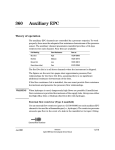
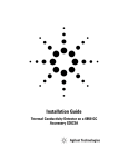
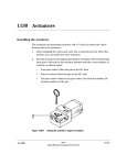
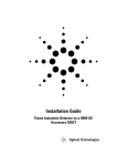
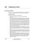
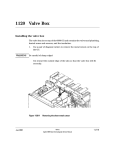
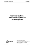
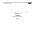
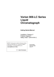
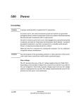
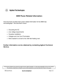
410
Covers and Fans
Plastic covers
ALS tray bracket (replaces
Pneumatics cover
Injection port cover) on GC’s
with S/N < 20,000
Injection port fan cover
Injection port cover
Detector cover
Electronics carrier cover
Left side cover
Right side cover
Figure 410-1
Jun 2001
Plastic covers
Mainframe
Agilent 6890 Gas Chromatograph Service Manual
1 of 20
410
Covers and Fans
Metal covers
Metal covers
Pneumatics RFI shielding
Top rear cover
Bottom rear cover
Oven exhaust deflector
Figure 410-2
2 of 20
Metal covers
Mainframe
Agilent 6890 Gas Chromatograph Service Manual
Jun 2001
Covers and Fans
Removing the electronics cover
410
Removing the electronics cover
The electronics carrier cover is located on the right, top side of the 6890 GC.
WARNING
The electronics carrier cover shields the high voltage components on the main
board. Turn off the main power switch and unplug the power cord before
removing this cover.
Caution
Be sure to wear an ESD strap grounded to the 6890 GC chassis while
performing this procedure.
1.
Remove the GC’s right side cover.
2.
Reach under the electronics carrier cover and depress the rear locking
tab towards the front of the instrument.
Rear locking tab
(not shown)
Electronics cover
Notch
Front locking tab
Figure 410-3
Jun 2001
Removing the electronics cover
3.
While depressing the tab, lift up on the back of the electronics carrier
cover and slide the cover back, up, and out of the instrument.
4.
To reinstall the cover, make sure that notched edge of the cover faces the
front, left side of the instrument and snap it back into place.
Mainframe
Agilent 6890 Gas Chromatograph Service Manual
3 of 20
410
Covers and Fans
Removing the detector cover
Removing the detector cover
The top cover protects the detectors, valve box, and valve assembly.
If your detector cover mounts in a bracket on the GC oven:
1.
Tilt the front cover up.
2.
Squeeze the clip on the right hinge, pull the clip toward you and pivot it up.
Figure 410-4
Removing the detector cover
3.
Push the metal pin behind the clip to the left.
4.
Slide the detector cover to the right and lift it off.
5.
To replace the top cover:
a.
Slide the plastic post on the left side of the cover into the hole on the
injection port fan cover.
b.
Line up the hole in the tab on the right side of the cover with the
metal pin and push the pin to the right, through the hole.
c.
Pivot the clip back down and snap it back over the metal pin.
If your detector cover rests on a post on the electronic cover
4 of 20
Mainframe
Agilent 6890 Gas Chromatograph Service Manual
Jun 2001
Covers and Fans
If your detector cover rests on a post on the electronic cover
1.
Raise the detector cover to the straight-up position.
2.
Tilt the cover to the left to remove it.
410
Top cover
Electronics cover
Figure 410-5
Jun 2001
Removing the detector cover
Mainframe
Agilent 6890 Gas Chromatograph Service Manual
5 of 20
410
Covers and Fans
Replacing the detector top cover
Replacing the detector top cover
If your detector top cover currently mounts on a metal hinge, the hinge must
be removed before a new detector top cover can be installed. Examine the
area behind the detector locations. If there is a metal hinge present, it must
be removed so that the new detector top cover can be installed.
Metal hinge
Figure 410-6
1.
Caution
6 of 20
Locating the metal hinge, if present
The hinge, if present, is held to the oven top by two rivets and to the
bracket behind it by one rivet. Use a 1/4-inch bit in an electric drill to
remove the three rivets. Discard the hinge.
Be careful not to drill too deep. Remove only the rivet heads.
Mainframe
Agilent 6890 Gas Chromatograph Service Manual
Jun 2001
Covers and Fans
Replacing the detector top cover
Figure 410-7
2.
Jun 2001
410
Removing the hinge
Install the new electronic carrier cover. Holding the detector cover
upright, tilt it to the left, and insert the left hand pin of the into the hole
in the inlet fan cover. Rest the right side hinge on the electronics carrier
cover pin. See Removing the detector cover for more details.
Mainframe
Agilent 6890 Gas Chromatograph Service Manual
7 of 20
410
Covers and Fans
Removing the pneumatics top cover
Removing the pneumatics top cover
The large plastic cover over the pneumatics area on the top, rear of the GC
simply lifts off. To replace the cover, line up the holes in the top of the cover
with any pneumatics fittings and regulator dials and snap it back into place.
Removing the pneumatics RFI shielding
An aluminum cover shields the top of the pneumatics area at the top, rear of
the instrument.
1.
Remove the plastic pneumatics cover and remove the one Torx T-20 screw
from the top of the metal RFI shielding.
2.
From the rear of the GC, slide the RFI shielding to the left, out from under
the locking tabs, and lift it off.
Figure 410-8
8 of 20
Removing the RFI shielding
Mainframe
Agilent 6890 Gas Chromatograph Service Manual
Jun 2001
Covers and Fans
Removing the left side cover
410
Removing the left side cover
1.
Fully loosen the two captive screws (Torx T-20) at the top of the cover.
Figure 410-9
2.
Removing the left side cover
Slide the side cover slightly to the rear of the GC and lift the cover out of
the slot in the bottom of the chassis to remove it.
When replacing the cover, be sure any wires or pneumatic lines are properly
routed so that they are not pinched by the cover.
Jun 2001
Mainframe
Agilent 6890 Gas Chromatograph Service Manual
9 of 20
410
Covers and Fans
Removing the right side cover
Removing the right side cover
1.
Fully loosen the two captive screws (Torx T-20) at the top of the cover.
Figure 410-10
2.
10 of 20
Removing the right side cover
Slide the side cover slightly to the rear of the GC and lift the cover out of
the slot in the bottom of the chassis to remove it.
Mainframe
Agilent 6890 Gas Chromatograph Service Manual
Jun 2001
Covers and Fans
Removing the ALS tray bracket
410
Removing the ALS tray bracket
When a 7673 Automatic Liquid Sampler is installed on a 6890 GC (serial
number < 20,000), a large plastic tray bracket replaces the blue inlet carrier
cover. Follow the procedure below to remove this bracket.
1.
Remove the two screws located on the under side of the rounded end of
the tray bracket assembly using a T-20 Torx driver.
2.
Remove the two screws at either end of the tray mounting strap using a
T-20 Torx driver.
3.
Remove six screws attaching the bracket assembly to the inlet chassis
using a T-20 Torx driver. Lift the assembly straight up.
Screws (6)
Tray bracket assembly
Screw (2)
M4 ×10 PH Torx
GC mainframe
Left side cover
Tray mounting strap
Screw (2), M4 ×18 FH Torx
Figure 410-11
Jun 2001
Removing the ALS tray bracket
Mainframe
Agilent 6890 Gas Chromatograph Service Manual
11 of 20
410
Covers and Fans
Removing the inlet carrier cover
Removing the inlet carrier cover
The inlet carrier cover is the blue plastic cover mounted over the two inlet
ports. To remove the cover, fully loosen the six Torx T-20 screws on the top
of the cover and lift off the cover. Some or all the screws are captive in the
cover.
Figure 410-12
Removing the inlet carrier cover
When re-installing the cover, make sure that all plumbing and wires are
properly routed in their channels.
12 of 20
Mainframe
Agilent 6890 Gas Chromatograph Service Manual
Jun 2001
Covers and Fans
Removing the inlet carrier
410
Removing the inlet carrier
The inlet carrier is the black, molded, plastic pallet mounted over the two
inlet ports underneath the blue cover.
1.
Remove the left side cover.
2.
Remove the blue cover from the inlet carrier.
3.
Unclip the four wiring harnesses from the left side of the inlet carrier.
Wiring harnesses
Figure 410-13
Jun 2001
Removing the inlet carrier
4.
Disconnect the fan from the connector to the right of the fan on the oven
top.
5.
Remove any installed inlets.
6.
Remove the four screws (Torx T-20) from the top of the carrier and
remove the carrier.
Mainframe
Agilent 6890 Gas Chromatograph Service Manual
13 of 20
410
Covers and Fans
Removing the rear covers
Removing the rear covers
There are two covers on the rear of the 6890 GC. The top cover shields the
EPC board and any inlet, detector and auxiliary pneumatics modules. The
bottom cover shields the oven fan motor, oven damper, the transformer and
the AC power board.
Removing the top rear cover
1.
Remove the plastic pneumatics top cover and the metal RFI shielding
cover over the auxiliary and detector pneumatic slots as described in this
section.
2.
Loosen the four Torx T-20 screws on the top, rear cover.
Figure 410-14
3.
14 of 20
Loosening the screws on the top rear cover
Slide the cover slightly up until it is free from the screws and then slide
the cover down and away from the GC. Carefully guide any installed inlet
plumbing out of the slots in the top of the cover.
Mainframe
Agilent 6890 Gas Chromatograph Service Manual
Jun 2001
Covers and Fans
Removing the rear covers
410
Removing the bottom rear cover
1.
Remove the top, rear cover (and RFI shielding) as described in the
previous procedure.
2.
Remove the two Torx T-20 screws (and washers) on the bottom of the
cover.
Figure 410-15
Jun 2001
Removing the screws on the bottom rear cover
3.
Slide the cover slightly up until it is free from the top screws. Pull the
cover straight off the GC.
4.
When replacing the bottom rear cover, be sure to reinstall the two lock
washers on the bottom screws.
Mainframe
Agilent 6890 Gas Chromatograph Service Manual
15 of 20
410
Covers and Fans
Removing the injection port fan cover
Removing the injection port fan cover
The injection port fan cover encloses the fan that draws air through the 6890
GC injection ports.
1.
Loosen the Torx T-20 screw on the right side of the fan cover.
2.
Slide the cover slightly to the right to disengage it from the left mounting
post and lift the cover up and off.
3.
Reassembly is the reverse of removal.
Removing the injection port fan
The injection port fan cools the injection ports by drawing air from under the
inlet carrier, across the installed inlets.
Note
16 of 20
1.
Remove the injection port fan cover as described in this section.
2.
Disconnect the fan’s wiring harness from the main wiring harness, to
right of the fan on top of the oven.
3.
Grasp the fan and snap it up and out of the inlet carrier.
When installing a new fan, be sure to install it so that it draws air from the
front of the GC, through the inlet carrier and out towards the rear of the GC.
The fan has raised arrows on its side indicating the direction of fan rotation
and the direction of air flow. On a correctly installed fan, one arrow should
point up and one to the right (when facing the front of the GC).
Mainframe
Agilent 6890 Gas Chromatograph Service Manual
Jun 2001
Covers and Fans
Removing the keyboard
410
Removing the keyboard
WARNING
High voltage components are exposed when servicing the instrument with
the covers removed. Turn off the main power switch and unplug the power
cord before proceeding.
Caution
Be sure to wear an ESD strap grounded to the 6890 GC chassis while
performing this procedure.
1.
Remove the right side cover from the instrument.
2.
Disconnect the display and keyboard ribbon cables from the main board
(P11, P12, P13).
P11
P12
J8
P13
Figure 410-16
3.
Jun 2001
Screw and keyboard/display connector locations
Remove the three 1/4-inch screws attaching the keyboard to the chassis.
There are two on the side of the GC near the main board and one at the
bottom of the main board carrier.
Mainframe
Agilent 6890 Gas Chromatograph Service Manual
17 of 20
410
Covers and Fans
Removing the pneumatics area fan
4.
Slide the keyboard assembly away from the main board and then pull it
out towards the front of the GC.
5.
Reassembly is the reverse of removal.
Removing the pneumatics area fan
This fan cools the area containing the EPC board and flow manifolds by
drawing air down through the pneumatics area. The fan mounts either directly
into the pneumatics chassis, or into a bracket which mounts into the chassis.
Examine your GC to determine the type of pneumatics fan installed.
Chassis mounted fan
18 of 20
1.
Remove the pneumatics cover, the top rear panel, and the bottom rear
panel. (You may need to remove the RFI cover.)
2.
Disconnect the fan’s connector from the main wiring harness.
3.
Remove the tie-wrap that secures the fan in the chassis.
4.
Slide the fan out and replace. Orient the new fan so that the wiring is on
the right side and the arrow indicator on the side of the fan points down.
Mainframe
Agilent 6890 Gas Chromatograph Service Manual
Jun 2001
Covers and Fans
Removing the pneumatics area fan
410
Air Flow
Figure 410-17
Replacing the pneumatics area fan
Bracket mounted fan
Jun 2001
1.
Remove the pneumatics cover, the top rear panel, and the bottom rear
panel. (You may need to remove the RFI cover.)
2.
Disconnect the fan’s connector from the main wiring harness.
Mainframe
Agilent 6890 Gas Chromatograph Service Manual
19 of 20
410
Covers and Fans
Removing the pneumatics area fan
Air flow
Figure 410-18
20 of 20
Removing the pneumatics area fan
3.
Remove the Torx T-20 screw from the bracket and slide the bracket out
of the back of the instrument
4.
Lift the retaining clip securing the fan in the bracket and slide the fan
out of the two retaining tabs. Remove the old fan.
5.
Lift the retaining tab and insert the new fan. Be sure to orient the fan so
that the arrow points downward when installed and the wires are on the
right side. Slide the fan under the retaining tabs until it snaps into place.
6.
Slide the tabs on the back of the fan bracket into the corresponding slots
underneath the EPC board area and reinstall the screw.
Mainframe
Agilent 6890 Gas Chromatograph Service Manual
Jun 2001