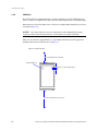
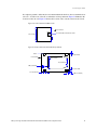
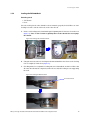
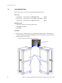
1
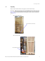
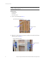
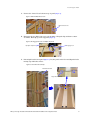
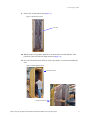
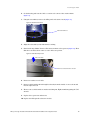
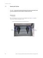
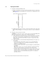
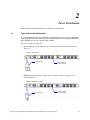
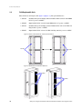
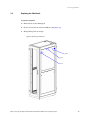
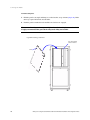
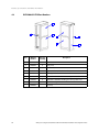
IBM System Storage DCS9550 and DCS9900 42U and 45U Rack Installation and Configuration Guide SC23-6659-02 The following paragraph does not apply to any country (or region) where such provisions are inconsistent with local law. INTERNATIONAL BUSINESS MACHINES CORPORATION PROVIDES THIS PUBLICATION “AS IS” WITHOUT WARRANTY OF ANY KIND, EITHER EXPRESS OR IMPLIED, INCLUDING, BUT NOT LIMITED TO, THE IMPLIED WARRANTIES OF MERCHANTABILITY OR FITNESS FOR A PARTICULAR PURPOSE. Some states (or regions) do not allow disclaimer of express or implied warranties in certain transactions; therefore, this statement may not apply to you. Order publications through your IBM representative or the IBM branch office serving your locality. No part of this document covered by copyright may be reproduced in any form or by any means—graphic, electronic, or mechanical, including photocopying, recording, taping, or storage in an electronic retrieval system—without prior written permission of the copyright owner. © Copyright International Business Machines Corporation 2007, 2008. US Government Users Restricted Rights – Use, duplication or disclosure restricted by GSA ADP Schedule Contract with IBM Corp. Preface Preface What is in this Guide This guide provides installation and maintenance information that is specific to the IBM System Storage DCS9550 and DCS9900 42U/45U racks. Who should use this Guide This guide should be used by service representative to install or repair the DCS9550 and DCS9900 42U/45U racks. Getting information, Help, and Service If you need help, service, or technical assistance or just want more information about IBM products, you will find a wide variety of sources available from IBM to assist you. This section contains information about where to go for additional information about IBM and IBM products, what to do if you experience a problem with your IBM System Storage DCS9550 or DCS9900 product, and whom to call for service, if it is necessary. Support Information For online support information for your IBM System Storage DCS9550 or DCS9900 product, visit the following web site: www.ibm.com/support For telephone support information, in the United States, contact IBM at 1-800-IBM-SERV (426-7378). In other countries, visit the following web site for support telephone numbers: www.ibm.com/planetwide/ Before You Call Before you call, make sure that you have taken these steps to try to solve the problem yourself: • Check all cables on your hardware to make sure that they are connected properly. • Check the power switches to make sure that the system is turned on. • Use the troubleshooting information in your system documentation and use the diagnostic tools that come with your system. Using the Documentation Information about the DCS9550 or DCS9900 products is available on a documentation CD that comes with your product. You can also access documents using the IBM Publications Center: http://www.ibm.com/shop/publications/order IBM System Storage DCS9550 and DCS9900 42U and 45U Rack Installation and Configuration Guide iii Preface International Standards This product complies with the applicable Information Technology (IT) standards set forth by EMC and product safety for world wide shipment. Qualified Personnel The personnel qualified to use this device are referred to within this document as follows: • Service Person: Someone with the appropriate and necessary technical training and experience to be aware of hazards to which they may be exposed in performing a task and of measures to minimize the risks to that person or other persons. • User/Operator: Any person authorized to handle/operate the product other than a Service Person. Delivery and Subsequent Transportation of the Equipment You must prepare your environment to accept the new product based on the installation planning information provided, with assistance from an IBM Installation Planning Representative (IPR) or IBM authorized service provider. In anticipation of the equipment delivery, prepare the final installation site in advance so that professional movers or riggers can transport the equipment to the final installation site within the computer room. If for some reason, this is not possible at the time of delivery, you must make arrangements to have professional movers or riggers return to finish the transportation at a later date. Only professional movers or riggers should transport the equipment. The IBM authorized service provider can only perform minimal frame repositioning within the computer room, as needed, to perform required service actions. You are also responsible for using professional movers or riggers when you relocate or dispose of equipment. When relocating the DCS9900 rack with 1269-3S1 draws installed, the hard drives installed in the drawers must be removed to avoid a side-to-side tip-over hazard. Rack System Precautions Elevated Operating Ambient Temperature The rack design should take into consideration the maximum operating ambient temperature for the unit. If installed in a closed or multi-unit rack assembly, the operating ambient temperature of the rack environment may be greater than room ambient. Therefore, consideration should be given to installing the system in an environment compatible with the system’s maximum rated ambient temperature. iv IBM System Storage DCS9550 and DCS9900 42U and 45U Rack Installation and Configuration Guide Preface Reduced Air Flow Installation of the system in a rack should be such that the amount of air flow required for safe operation of the system is not compromised. Mechanical Loading Mounting of the system in the rack should be such that a hazardous condition does not occur due to uneven mechanical loading. The rack design should incorporate stabilizing features suitable to prevent the rack from tipping during installation. When loading a rack with the enclosures, fill the rack from the bottom up and empty from the top down. The rack design should incorporate stabilizing features suitable to prevent the rack from tipping or being pushed over in normal use. Circuit Overloading Consideration should be given to the connection of the system to the supply circuit and the effect that overloading of circuits might have on overcurrent protection and supply wiring. The rack should have a safe electrical distribution system. It must provide overcurrent protection for the unit and must not be overloaded by the total number of units installed in the rack. Consideration of the units nameplate rating should be used when addressing these concerns. Reliable Earthing Reliable earthing of rack-mounted systems should be maintained. Particular attention should be given to supply connections other than direct connections to the branch circuit (e.g. use of power distribution units). The electrical distribution system must provide a reliable earth for each unit and the rack. The design of the electrical distribution system must take into consideration the total earth leakage current from all the power supplies in all the units. The rack will require labeling with “HIGH LEAKAGE CURRENT. Earth connection essential before connecting supply”. Rack Relocation Observe the following precautions when you need to relocate your rack: • Before you add or remove drawers, always lower the leveling feet and install the antitip plates, or have the rack bolted to the floor. • Always install drawers at the bottom of the rack first. • Always remove drawers from the top of the rack first. • Always install the heaviest drawers on the bottom of the rack. • Never push on the sides of the rack. • When relocating the DCS9900 rack with 1269-3S1 draws installed, the hard drives installed in the drawers must be removed to avoid a side-to-side tip-over hazard. IBM System Storage DCS9550 and DCS9900 42U and 45U Rack Installation and Configuration Guide v Preface Taiwan Contact Information How to Send Your Comments Your feedback is important in helping us to provide the most accurate and high-quality information. If you have comments or suggestions for improving this publication, you can send us comments electronically by using the following address: Internet: [email protected] You can also mail your comments by using the Readers’ Comments Form in the back of this manual or direct your mail to: International Business Machines Corporation Information Development Dept. GZW 9000 South Rita Road Tucson, AZ 85744–0001 U.S.A. vi IBM System Storage DCS9550 and DCS9900 42U and 45U Rack Installation and Configuration Guide Table of Contents Table of Contents Installing the Rack 1.1 1.2 1.3 1.4 1.4.1 1.4.2 1.5 1.5.1 1.5.2 1.6 1.7 1.8 Site Pre-Installation Inspection . . . . . . . . . . . . . . . . . . . . . . . . . . . . . . . . . . . . . . . . . . . . . . . . . . . 1 Handling Verification . . . . . . . . . . . . . . . . . . . . . . . . . . . . . . . . . . . . . . . . . . . . . . . . . . . . . . . . . . . . 2 Unpacking . . . . . . . . . . . . . . . . . . . . . . . . . . . . . . . . . . . . . . . . . . . . . . . . . . . . . . . . . . . . . . . . . . . . . 3 Positioning the Rack . . . . . . . . . . . . . . . . . . . . . . . . . . . . . . . . . . . . . . . . . . . . . . . . . . . . . . . . . . . . 9 42U Racks . . . . . . . . . . . . . . . . . . . . . . . . . . . . . . . . . . . . . . . . . . . . . . . . . . . . . . . . . . . . . . . . . . 9 45U Racks . . . . . . . . . . . . . . . . . . . . . . . . . . . . . . . . . . . . . . . . . . . . . . . . . . . . . . . . . . . . . . . . . 10 Leveling the Rack . . . . . . . . . . . . . . . . . . . . . . . . . . . . . . . . . . . . . . . . . . . . . . . . . . . . . . . . . . . . . . 12 Leveling the DCS9550 Rack . . . . . . . . . . . . . . . . . . . . . . . . . . . . . . . . . . . . . . . . . . . . . . . . . . . 12 Leveling the DCS9900 Rack . . . . . . . . . . . . . . . . . . . . . . . . . . . . . . . . . . . . . . . . . . . . . . . . . . . 13 Joining Multiple Racks. . . . . . . . . . . . . . . . . . . . . . . . . . . . . . . . . . . . . . . . . . . . . . . . . . . . . . . . . . 14 Attaching Anti-Tip Plates. . . . . . . . . . . . . . . . . . . . . . . . . . . . . . . . . . . . . . . . . . . . . . . . . . . . . . . . 16 Powering On the Rack . . . . . . . . . . . . . . . . . . . . . . . . . . . . . . . . . . . . . . . . . . . . . . . . . . . . . . . . . . 17 Power Distribution 2.1 2.2 Types of Power Distribution Units. . . . . . . . . . . . . . . . . . . . . . . . . . . . . . . . . . . . . . . . . . . . . . . . 19 Field Replaceable Units. . . . . . . . . . . . . . . . . . . . . . . . . . . . . . . . . . . . . . . . . . . . . . . . . . . . . . . . . 20 Servicing the Racks 3.1 3.2 3.3 3.4 Replacing the PDU . . . . . . . . . . . . . . . . . . . . . . . . . . . . . . . . . . . . . . . . . . . . . . . . . . . . . . . . . . . . . Replacing the Doors. . . . . . . . . . . . . . . . . . . . . . . . . . . . . . . . . . . . . . . . . . . . . . . . . . . . . . . . . . . . Replacing the Side Panels . . . . . . . . . . . . . . . . . . . . . . . . . . . . . . . . . . . . . . . . . . . . . . . . . . . . . . . Relocating a Rack. . . . . . . . . . . . . . . . . . . . . . . . . . . . . . . . . . . . . . . . . . . . . . . . . . . . . . . . . . . . . . 21 24 25 27 Product Specifications and Parts Information 4.1 4.2 4.3 4.4 4.5 Product Specifications. . . . . . . . . . . . . . . . . . . . . . . . . . . . . . . . . . . . . . . . . . . . . . . . . . . . . . . . . . DCS9550 42U FRU Part Numbers . . . . . . . . . . . . . . . . . . . . . . . . . . . . . . . . . . . . . . . . . . . . . . . . DCS9550 45U FRU Part Numbers . . . . . . . . . . . . . . . . . . . . . . . . . . . . . . . . . . . . . . . . . . . . . . . . DCS9900 45U FRU Part Numbers . . . . . . . . . . . . . . . . . . . . . . . . . . . . . . . . . . . . . . . . . . . . . . . . DCS9900 42U FRU Part Numbers . . . . . . . . . . . . . . . . . . . . . . . . . . . . . . . . . . . . . . . . . . . . . . . . 29 30 31 32 33 Index . . . . . . . . . . . . . . . . . . . . . . . . . . . . . . . . . . . . . . . . . . . . . . . . . . . . . . . . . . . . . . . . . . . . . . . . . . . . . . . 35 IBM System Storage DCS9550 and DCS9900 42U and 45U Rack Installation and Configuration Guide vii This page intentionally left blank. viii 1 Installing the Rack This chapter contains the procedures for installing the rack and preparing it for operation. 1.1 Site Pre-Installation Inspection Given the weight and size of the rack, it is possible that the rack may tip over while moving. ! Warning The rack must be removed from the shipping crate using a minimum of 2 people. The rack may not be tipped more than 10 degrees, either from a level surface or rolling down an incline (ramp). Before a rack can be installed, a site inspection needs to be done and questions need to be answered to assure a successful installation. Questions to answer: 1. Where will the crate be dropped off? 2. Are there obstacles in the way at drop off point, such as steps and slope, complicating rack removal from crate? 3. Can the rack be wheeled to destination without obstacles such as low door hangs and low building components? 4. Is a sufficient power source installed and appropriate for customers desired configuration? 5. Are temperature, BTU cooling, and humidity of the room appropriate? 6. Are the floor tiles rated properly to hold the rack weight? If any of these questions are not fully addressed, precautionary measures might be needed at time of product deployment to create a successful installation. IBM System Storage DCS9550 and DCS9900 42U and 45U Rack Installation and Configuration Guide 1 Installing the Rack 1.2 Handling Verification The procedure described in this section applies to both 42U and 45U racks. 1. Visually inspect the crate for signs of external damage. If you detect any problems, follow the instructions given in the “Physical Transit Damage and TMC Incident Data Sheet” (which is attached to the crate) to report damage. 2. There are two tilt monitor cards (TMC) attached to the left and front of the crate to indicate if the crate has been tipped over in transit (Figure 1). On both TMCs, verify that the silver disks are still visible in the windows (Figure 2). If a tripped TMC is observed (red dot in window), follow the instructions given in the “Physical Transit Damage and TMC Incident Data Sheet” to report damage. Figure 1. Tilt Monitor Cards on Crate Tilt Monitor Card Tilt Monitor Card Figure 2. Views of TMC (Normal & Tripped) Window Clock View of TMC that has not been tripped: Silver Disk falls into window (small hole in disk is visible) Clock shows current time and date GMT 2 View of TMC that has been tripped: FULL red dot visible in window Clock is flashing two different dates & times (tripped time and armed time, GMT) IBM System Storage DCS9550 and DCS9900 42U and 45U Rack Installation and Configuration Guide Installing the Rack 1.3 Unpacking The procedure described in this section applies to both 42U and 45U racks. CAUTION: When transporting the crate, insert forklift from the two sides of crate only (Figure 3). To prevent the pallet jack from breaking the crate base, only insert forklift 3/4 way in (Figure 4). Figure 3. Using Forklift on Crate Insert Forklift from Side of Crate Only Figure 4. Inserting Forklift Insert Forklift 3/4 Way In Only IBM System Storage DCS9550 and DCS9900 42U and 45U Rack Installation and Configuration Guide 3 Installing the Rack NOTE: Make sure you have enough space in front of the crate. The crate door will be used as a ramp for rolling out the rack. Tools Required: • Cutter/scissors • 3/4" Wrench • 3/16" Allen wrench 1. Cut the center fastening strip (Figure 5). Figure 5. Opening the Shipping Crate Do Not Cut Cut Center Strip Only 2. Engage the two ramp supports on front panel—pull the pin out, turn the swivel leg up and release pin to lock (Figure 6). Figure 6. Engage Ramp Supports Engage Ramp Supports 4 IBM System Storage DCS9550 and DCS9900 42U and 45U Rack Installation and Configuration Guide Installing the Rack 3. Remove the 2 metal cleat locks near top of panel (Figure 7). Figure 7. Remove Metal Cleat Locks Remove Cleat Locks 4. Disengage the two link locks at top on both sides—lift up the flap and turn counterclockwise. Then flip open the top panel (Figure 8). Figure 8. Disengage Link Locks and Open Top Panel Disengage Lock Flip Open Top Panel 5. Lift and pull out the front panel (Figure 9). Lay the panel on the floor and align the holes in ramp top with bolts on base. Figure 9. Set Front Panel as Ramp Pull Out Front Panel Align Holes with Bolts IBM System Storage DCS9550 and DCS9900 42U and 45U Rack Installation and Configuration Guide 5 Installing the Rack 6. Remove the ramp extension panel from left side of crate (Figure 10). Place the extension at end of ramp, making sure the two velcro fasteners are secure. Figure 10. Set Up Ramp Extension Fasten Velcro Ramp Extension Panel 7. Remove the 2 metal cleat locks from rear panel (Figure 11). Remove and set panel aside. Figure 11. Remove Metal Cleat Locks Remove Metal Cleat Locks 8. Verify that the 4 leveling nuts/feet at the bottom corners of rack are raised to the maximum height so they will not scratch the floor when the rack is moved (Figure 12). Use the wrench to adjust if necessary. Figure 12. Leveling Nut/Foot Position DCS9550 Rack Leveling Nut 6 DCS9900 Rack Leveling Foot IBM System Storage DCS9550 and DCS9900 42U and 45U Rack Installation and Configuration Guide Installing the Rack 9. Remove the 2 foam pads at front (Figure 13). Figure 13. Remove Foam Pads Foam Pad 10. With the help of your partner, push the rack out from the rear side while the other person steer the rack down the ramp from front (Figure 14). 11. Once the rack is rolled onto the floor, remove the plastic cover. Then reassemble the crate. Figure 14. Pushing Out the Rack Push Out from Rear Steer Down from Front IBM System Storage DCS9550 and DCS9900 42U and 45U Rack Installation and Configuration Guide 7 Installing the Rack 12. Remove the stiffener panels that are attached to the rack during shipment (Figure 15). Figure 15. Remove Stiffener Panels Remove Panels 13. Verify that the locks on the side panels are engaged (Figure 16). CAUTION: The side panels can potentially be a hazard when they become unlatched. It is highly recommended that you lock the side panels if they are installed. Figure 16. Locks on Side Panels Panel Lock 8 IBM System Storage DCS9550 and DCS9900 42U and 45U Rack Installation and Configuration Guide Installing the Rack 1.4 Positioning the Rack 1.4.1 42U Racks For 42U racks populated with 16-bay enclosures, the recommended service clearances are 48" (1219.20mm) from the front and 36" (914.40mm) from the rear of the rack (Figure 17). No service clearance is required on the side of the rack. The height clearance is 84" (2133.6mm). NOTE: The service clearance is only one of the factors used to determine floor layout. Cooling is another major factor that must be considered for your specific site/facility. There are cut-out holes, approximately 3.0" (76.20mm) in diameter, on the top panel for passing cables into the rack from above (Figure 17). Figure 17. Top View of Rack Cable Cut-Out Hole 48" (1219.20mm) Clearance from Front 36" (914.40mm) Clearance from Rear Approx. 3.0" (76.20mm) Diameter If you plan to pass the cables into the rack from underneath the floor, the recommended cutout is 6" × 6" in the rear of the tile on which the rack is positioned. Figure 18 illustrates the location for the cut-out. Figure 19 shows the location of the castors at the bottom of rack. Figure 18. Location of Cable Cut-Out in Floor 9" Rear of Rack 6" x 6" Cut-Out at Rear Center of Tile 24" x 24" Tile 9" Figure 19. Location of Castors (Viewed from Top of Rack) Castor 1.44" (36.58mm) Front of Rack 18" (457.20mm) 12" (304.80mm) 2.44" (61.98mm) 2.37" (60.20mm) 3.37" (85.60mm) IBM System Storage DCS9550 and DCS9900 42U and 45U Rack Installation and Configuration Guide 2.44" (61.98mm) 9 Installing the Rack 1.4.2 45U Racks For 45U racks, the recommended service clearance from the rear is 36" (914.40mm). No service clearance is required on the side of the rack. The height clearance is 89" (2260.6mm). From the front, 54" (1371.60mm) service clearance is required when using 48-bay or 60-bay enclosures (Figure 20). NOTE: The service clearance is only one of the factors used to determine floor layout. Cooling is another major factor that must be considered for your specific site/facility. There are cut-out holes, approximately 3.0" (76.20mm) in diameter, on the top panel for passing cables into the rack from above (Figure 20). Figure 20. Top View of Rack 36" (914.40mm) Clearance from Rear Cable Cut-Out Hole Approx. 3.0" (76.20mm) Diameter 54" (1371.60mm) Clearance from Front 10 IBM System Storage DCS9550 and DCS9900 42U and 45U Rack Installation and Configuration Guide Installing the Rack If you plan to pass the cables into the rack from underneath the floor, the recommended cutout is 6" × 6" in the rear of the tile on which the rack is positioned. Figure 21 illustrates the location for the cut-out. Figure 22 shows the location of the castors at the bottom of rack. Figure 21. Location of Cable Cut-Out in Floor 9" Rear of Rack 6" x 6" Cut-Out at Rear Center of Tile 24" x 24" Tile 9" Figure 22. Location of Castors (Viewed from Top of Rack) Castor 1.44" (36.58mm) Front of Rack 18" (457.20mm) 12" (304.80mm) 2.44" (61.98mm) 2.37" (60.20mm) 3.37" (85.60mm) IBM System Storage DCS9550 and DCS9900 42U and 45U Rack Installation and Configuration Guide 2.44" (61.98mm) 11 Installing the Rack 1.5 Leveling the Rack NOTE: If you are joining multiple racks, skip this section and proceed to Section 1.6. 1.5.1 Leveling the DCS9550 Rack Tools Required: • 3/4" Wrench • Level Once the rack is placed at the desired location, it must be properly leveled. 1. Place the 4 leveling feet, included in the accessory kit, under the leveling nut at the corners of the rack (Figure 23). Figure 23. Leveling the DCS9550 Rack (1) Leveling Nut Stud Leveling Foot 2. Using the 3/4" wrench, turn each leveling nut downward until the stud is fully inserted and the wheel next to the leveling foot is completely off the floor (Figure 24). Figure 24. Leveling the DCS9550 Rack (2) Turn Nut Downward Wheel is Off the Floor Leveling Foot 3. Checking with a level, adjust the leveling nut as needed until the rack is level.Note that all caster wheels must be completely off the floor so only the leveling feet are supporting the rack. 12 IBM System Storage DCS9550 and DCS9900 42U and 45U Rack Installation and Configuration Guide Installing the Rack 1.5.2 Leveling the DCS9900 Rack Tools Required: • 3/4" Wrench • Level Once the rack is placed at the desired location, it must be properly leveled. There are four leveling feet at the corners of the rack, next to the wheels. 1. Rotate each leveling foot by hand with a quick “spinning wheel” motion to lower the foot (Figure 25). Note: A slow rotation or pulling down on the thread does not engage the thread. Figure 25. Leveling Foot on DCS9900 Rack 2. Using the wrench, turn each leveling nut downward until the wheel next to the leveling foot is completely off the floor (Figure 26). 3. Checking with a level, adjust the leveling nut as needed until the rack is level.Note that all caster wheels must be completely off the floor so only the leveling feet are supporting the rack. Figure 26. Leveling the DCS9900 Rack Turn Nut Downward IBM System Storage DCS9550 and DCS9900 42U and 45U Rack Installation and Configuration Guide 13 Installing the Rack 1.6 Joining Multiple Racks Follow these steps to join two or more racks together side-by-side. Parts List: • 11-00154-016 Bolt, 1/4-20× 1.0", HEX, PSZ, RoHS [Qty 4] • 13-R0039-001 Washer, ID.315, OD.74, THK.06, PSZ, RoHS [Qty 8] • 12-R0019-001 Nut, Wing, 1/4-20, HEX, PSZ, RoHS [Qty 4] Tools Required: • 7/16" socket wrench or 7/16" open-end wrench • #2 Phillips screwdriver • Step-ladder Procedure: 1. Remove the two “inside” (sides to be joined) side panels from racks—disengage the locks, then release the latches and pull the panel out and up (Figure 27). Store the side panels for future use if desired. Figure 27. Removing the Side Panels and Hole Covers Pop Out Cover Remove Panels 14 IBM System Storage DCS9550 and DCS9900 42U and 45U Rack Installation and Configuration Guide Installing the Rack 2. On both racks, push out the 8 hole covers in each corner of the exterior frame (Figure 27). 3. Using the screwdriver, remove the filler panel on bottom of rack (Figure 28). Figure 28. Remove Filler Panel Filler Panel Removed 4. Align the racks side by side with frames touching. 5. Stand on the step-ladder. Remove all four screws from each top screen (Figure 29). Then slide the screens back for easier access to holes at top front. Figure 29. Slide Back Top Screen Slide Screen Back Remove Screws at 4 Corners of Screen 6. Insert one washer on each bolt. 7. Insert each bolt with washer through both racks, from the inside of one rack out and into the adjacent rack. 8. Then secure each bolt with one washer and wing nut. Tighten until snug using the 7/16" wrench. 9. Replace the top screens and screws. 10. Replace the filler panels at bottom of racks. IBM System Storage DCS9550 and DCS9900 42U and 45U Rack Installation and Configuration Guide 15 Installing the Rack 1.7 Attaching Anti-Tip Plates CAUTION: Anti-tip plates must be firmly attached to the bottom of the rack to prevent the rack from tipping over when the drawers are pulled out of the rack. Tools Required: • 7/16" wrench Place the anti-tip plate at bottom front of rack, aligning the holes (Figure 30). Using the wrench, attach 2 bolts to fasten plate to rack. Figure 30. Attaching Anti-Tip Plates to Front of DCS9900 Rack Attach Bolt Here 16 Attach Bolt Here IBM System Storage DCS9550 and DCS9900 42U and 45U Rack Installation and Configuration Guide Installing the Rack 1.8 Powering On the Rack 1. Perform the following grounding checks: a) With the external power cord connected to the system unit, check for 0.1 ohm or less resistance between the ground plug on the external power cord plug and the metal frame (Figure 31). Figure 31. Grounding Check on an DCS9550 Rack b) Using the appropriate probe, check for 0.1 ohm or less resistance between the metal frame and the grounding pin on each of the power outlets on each power distribution bus. 2. Verify that your ac power source is ready: CAUTION: Do not touch the receptacle or the receptacle face plate with anything other than your test probes before you have met the requirements in this step. i) Turn off the branch circuit breaker for the ac power outlet that the rack will plug into. Attach a “Do Not Operate” tag (S229-0237) to the circuit breaker switch. Note: All measurements are made with the receptacle face plate in the normal installed position. ii) Some receptacles are enclosed in metal housings. For this type of receptacle, do the following: • Check for less than 1 volt from the receptacle case to any grounded metal structure in the building, such as a raised-floor metal structure, water pipe, building steel, and similar structure. • Check for less than 1 volt from the receptacle ground pin to a grounded point in the building. Note: If the receptacle case or face plate is painted, be sure that the probe tip penetrates the paint and makes good electrical contact with the metal. • Check the resistance from the ground pin of the receptacle to the receptacle case. Check the resistance from the ground pin to the building ground. The readings should be less than 1.0 ohm, which indicates the presence of a continuous grounding conductor. IBM System Storage DCS9550 and DCS9900 42U and 45U Rack Installation and Configuration Guide 17 Installing the Rack iii) If any of the three checks that you made in Step (ii) above are not correct, remove the power from the branch circuit and make the wiring corrections; then check the receptacle again. Note: Do not use a digital multimeter to measure grounding resistance in the following steps. iv) Check for infinite resistance between the ground pin of the receptacle and each of the phase pins. This is a check for a wiring short to ground or a wiring reversal. v) Check for infinite resistance between the phase pins. This is a check for a wiring short. CAUTION: If the reading is other than infinity, do not proceed! Make the necessary wiring corrections before continuing. Do not turn on the branch circuit breaker until all the above steps are satisfactorily completed. vi) Turn on the branch circuit breaker. Measure for the appropriate voltages between phases. If no voltage is present on the receptacle case or the ground pin, the receptacle is safe to touch. vii) With an appropriate meter, verify that the voltage at the ac outlet is correct. viii) Verify that the grounding impedance is correct by using the ECOS 1020, 1023, B7106, C7106, or an appropriately approved ground impedance tester. 3. Plug in all the drawer power cords to the PDUs. 4. Connect the power cord of each PDU to your ac power outlets. For maximum power redundancy, connect the two sets of PDU to two different wall circuits, i.e. connect the left PDU power cords to wall circuit power feed #1 and the right PDU power cords to wall circuit power feed #2. 5. Turn on all switches on each PDU and verify that the 2 power LEDs on each PDU are on. 6. Follow the power on procedures for your drawers. 18 IBM System Storage DCS9550 and DCS9900 42U and 45U Rack Installation and Configuration Guide 2 Power Distribution This chapter provides information on the PDU used with the racks. 2.1 Types of Power Distribution Units Power is distributed to the enclosures and controllers in the rack by the power distribution units (PDU). PDUs must be installed in pairs. Each DCS9550 rack is configured with 4 PDUs. Each DCS9900 45U rack is configured with 8 PDUs. Two types of PDU are supported: • IEC 309 plug type has 8 × IEC 320-C13, 200-240V receptacles and 2 power switches (Figure 32) Figure 32. IEC 309 PDU 30A, 250V Plug 20A Circuit Breaker with Rocket Switch • NEMA L6-30P plug type has 8 × IEC 320-C13, 200-240V receptacles and 2 power switches (Figure 33) Figure 33. NEMA L6-30P PDU 30A, 250V Plug IBM System Storage DCS9550 and DCS9900 42U and 45U Rack Installation and Configuration Guide 20A Circuit Breaker with Rocket Switch 19 Power Distribution 2.2 Field Replaceable Units These PDUs are field replaceable (Figure 34)(Figure 35). The part numbers are: • 95P5362 DCS9900 PDU (left and right) and left DCS9550 PDU 30A 250V with NEMA L6-30 15' power cord FRU • 95P6972 Right DCS9550 PDU 30A 250V with NEMA L6-30 15' power cord FRU • 95P5363 DCS9900 PDU (left and right) and left DCS9550 PDU 30A or 250V IEC 309 Plug and 14-6" power cord FRU • 95P6973 Right DCS9550 PDU 30A or 250V IEC 309 Plug and 14-6" power cord FRU Figure 34. PDUs on DCS9550 Racks and DCS9900 42U Rack Left PDU Front of Rack Right PDU Figure 35. PDU Positions on DCS9900 45U Rack (4) PDUs (4) PDUs 20 IBM System Storage DCS9550 and DCS9900 42U and 45U Rack Installation and Configuration Guide 3 Servicing the Racks This chapter provides information on how to replace the PDUs and doors on the racks. 3.1 Replacing the PDU Tools Required: • 7/16" wrench • 3/8" wrench • #2 Phillips screwdriver There are 4 PDUs installed in the DCS9550 42U/45U racks and DCS9900 42U rack, two on each side attached to a mounting bracket. Figure 36 illustrates the locations of the PDU in the racks. Figure 36. PDU Positions on Rear of DCS9550 45U/42U Racks and DCS9900 42U Rack Top PDUs Bottom PDU Bottom PDU IBM System Storage DCS9550 and DCS9900 42U and 45U Rack Installation and Configuration Guide 21 Servicing the Racks There are 8 PDUs installed in the DCS9900 45U rack, four on each side attached to two mounting brackets. The side panel(s) must be removed when you need to access the PDUs. Figure 37 illustrates the location of the PDUs in the DCS9900 rack. Figure 37. PDU Positions on DCS9900 Rack (4) Right PDUs (4) Left PDUs A PDU can be replaced in the field if it is found to be defective. Follow these steps to replace a PDU: 1. Turn off all power switches on the defective PDU and unplug it from the ac power source. For DCS9900 45U rack, remove the side panel to access the PDU. 2. Determine which power supply modules must be turned off to service the defective PDU. Then turn off those modules and unplug their power cords from the defective PDU. 22 IBM System Storage DCS9550 and DCS9900 42U and 45U Rack Installation and Configuration Guide Servicing the Racks 3. Using the 7/16" wrench, remove the top and bottom bolts from the PDU mounting rail (Figure 38). Be careful to support the mounting rail after you have removed the bolts. Figure 38. Remove Bolts from PDU Mounting Rail Remove Top and Bottom Bolts 4. Flip over the mounting rail. Using the 3/8" wrench and #2 Phillips screwdriver, remove the 2 screws and nuts to detach the defective PDU from mounting rail (Figure 39). Figure 39. Remove Screws from PDU Remove Top and Bottom Screws 5. Attach the replacement PDU to the mounting rail using the 2 screws and nuts. 6. Attach the mounting rail to rack using the 2 bolts. 7. Connect the power supply modules’ power cords to the replacement PDU. 8. Connect the replacement PDU to your ac power outlet. 9. Turn on all switches on the PDU and verify that the 2 power LEDs are on. 10. Turn on the power supply modules. IBM System Storage DCS9550 and DCS9900 42U and 45U Rack Installation and Configuration Guide 23 Servicing the Racks 3.2 Replacing the Doors To remove a door: 1. Make sure the lock is disengaged. Press the lock button to release the door handle (Figure 40). Turn handle to open door. Figure 40. Door Handle Door Handle 2. Lift up to take the door off the hinges (Figure 41). Figure 41. Door Hinge Lift Up Door to Disengage To install a door: Hold the door close to rack, aligning the top and bottom hinges (Figure 42). Then place the hinges on door over hinge pins. Make sure both hinges are completely engaged. Figure 42. Front Door Top Hinge Align Hinges 24 IBM System Storage DCS9550 and DCS9900 42U and 45U Rack Installation and Configuration Guide Servicing the Racks 3.3 Replacing the Side Panels To remove a side panel: 1. Make sure the lock is disengaged. 2. Press to release the two latches simultaneously (Figure 43). 3. Then pull the panel out and up. Figure 43. Removing a Side Panel Latch Lock Latch IBM System Storage DCS9550 and DCS9900 42U and 45U Rack Installation and Configuration Guide 25 Servicing the Racks To install a side panel: 1. Hold the panel at an angle and hang it over the bracket at top of frame (Figure 44). Make sure top of panel is latched on both sides. 2. Push the panel towards the rack until the two latches are engaged. CAUTION: The side panels can potentially be a hazard when they become unlatched. It is highly recommended that you lock the side panels if they are installed. Figure 44. Installing a Side Panel Top of Panel Must Latch on Bracket Latch 26 IBM System Storage DCS9550 and DCS9900 42U and 45U Rack Installation and Configuration Guide Servicing the Racks 3.4 Relocating a Rack CAUTION: Removing components from the upper positions in the rack cabinet improves rack stability during relocation. If needed, reduce the weight of the rack cabinet by removing equipment starting at the top of the rack cabinet. After the rack has been relocated, restore the rack cabinet to its original configuration. NOTE: When relocating the DCS9900 rack with 1269-3S1 drawers installed, the hard drives installed in the drawers must be removed to avoid a side-to-side tip-over hazard. Follow these steps whenever you relocate a populated rack cabinet within a room or building. 1. Turn off all power to the rack and the system that is installed. 2. Disconnect all PDU power cords from the wall outlets and secure the power cords inside the rack. 3. Make sure that all anti-tip plates are installed. 4. Ensure that the heaviest devices are installed in the bottom of the rack cabinet. 5. Ensure that there are no empty U-levels between devices installed in the rack cabinet below the 25U level. 6. Remove all anti-tip plates. 7. If the rack cabinet you are relocating is part of a suite of rack cabinets, detach the rack cabinet from the suite. 8. Ensure that all devices, shelves, drawers, doors, and cables are secure. 9. Ensure that the four leveling feet are raised to their highest position. 10. Inspect the route that you plan to take when moving the rack to eliminate potential hazards: - Note: Do not use a ramp inclined at more than 10 degrees. - Verify that the route that you choose can support the weight of the loaded rack cabinet. Refer to Section 4.1 on page 29 for the weight of a loaded rack cabinet. IBM System Storage DCS9550 and DCS9900 42U and 45U Rack Installation and Configuration Guide 27 Servicing the Racks - Verify that all door openings are bigger than the rack. Refer to Section 4.1 on page 29 for the dimensions of rack cabinet. 11. With the help of your partner, carefully roll the rack to the new location. If a long distance relocation is required, restore the rack cabinet to the configuration as you received it. Pack the rack cabinet in the original packaging material, or equivalent. Once the rack cabinet is in the new location, do the following: 1. Lower the four leveling feet. 2. Level the rack. 3. Attach the anti-tip plates to the rack cabinet. 4. If previously removed, replace all the drawers and devices to their original rack location. 28 IBM System Storage DCS9550 and DCS9900 42U and 45U Rack Installation and Configuration Guide 4 Product Specifications and Parts Information This chapter provides the list of field replaceable unit (FRU) part numbers and product specifications. 4.1 Product Specifications 42U Wide Rack Specifications Height: 84" (2133.6 mm) Depth: With front and rear doors installed Less front and rear doors 44" (1117.6mm) 42" (1066.8mm) Width: With side panels installed 28" (711.2mm) Weight: Empty rack 380 lbs (172.73 kg) Max. weight with ten 16-bay enclosures and controller couplet 1216 lbs (552.73kg) Max. weight with ten 16-bay enclosures only 1108 lbs (503.64 kg) Max. weight with five 48-bay enclosures and controller couplet 1305 lbs (593.18 kg) Max. weight with five 48-bay enclosures only 1197 lbs (544.09 kg) 45U Wide Rack Specifications Height: 89" (2260.6mm) Depth: With front and rear doors installed Less front and rear doors 44" (1117.6mm) 42" (1066.8mm) Width: With side panels installed 28" (711.2mm) Weight: Empty rack 610 lbs (277.27 kg) Max. weight with ten 48-bay enclosures and controller couplet 2418 lbs (1099.09 kg) Max. weight with ten 48-bay enclosures only 2310 lbs (1050.0 kg) Max. weight with ten 60-bay enclosures and controller couplet 3090 lbs (1403.67 kg) Max. weight with ten 60-bay enclosures only 3010 lbs (1367.27 kg) IBM System Storage DCS9550 and DCS9900 42U and 45U Rack Installation and Configuration Guide 29 Product Specifications and Parts Information 4.2 DCS9550 42U FRU Part Numbers 2 1 2 2 4 2 3 5 Front of Rack 5 6 6 Right Side View Item FRU Part Number Units per Assembly 1 45E0992 1 Front door 2 45E1051 4 Side panel 3 45E1052 1 Left rear door 4 45E0993 1 Right rear door (with door handle) 5 95P6972 2 Right PDU 30A 220V with NEMA L6-30 15’ power cord 95P6973 2 Right PDU 30A or 250V IEC 309 Plug and 14-6" power cord 95P5362 2 Left PDU 30A 220V with NEMA L6-30 15’ power cord 95P5363 2 Left PDU 30A or 250V IEC 309 Plug and 14-6" power cord 45E0806 1 Anti-tip plate kit 6 30 Left Side View Description 95P5359 Baying kit 45E0807 Door key 95P6966 3U rack filler plate 95P6967 2U rack filler plate IBM System Storage DCS9550 and DCS9900 42U and 45U Rack Installation and Configuration Guide Product Specifications and Parts Information 4.3 DCS9550 45U FRU Part Numbers 2 1 2 2 4 2 3 5 Front of Rack 5 6 6 Right Side View Left Side View Item FRU Part Number Units per Assembly 1 95P5360 1 Front door 2 45E0803 4 Side panel 3 45E0804 1 Left rear door 4 45E0805 1 Right rear door (with door handle) 5 95P6972 2 Right PDU 30A 220V with NEMA L6-30 15’ power cord 95P6973 2 Right PDU 30A or 250V IEC 309 Plug and 14-6" power cord 95P5362 2 Left PDU 30A 220V with NEMA L6-30 15’ power cord 95P5363 2 Left PDU 30A or 250V IEC 309 Plug and 14-6" power cord 45E0806 1 Anti-tip plate kit 6 Description 95P5359 Baying kit 45E0807 Door key 95P6966 3U rack filler plate 95P6967 2U rack filler plate IBM System Storage DCS9550 and DCS9900 42U and 45U Rack Installation and Configuration Guide 31 Product Specifications and Parts Information 4.4 DCS9900 45U FRU Part Numbers 2 1 2 2 4 2 Item FRU Part Number Units per Assembly 1 46M5895 1 Front door 2 45E0803 4 Side panel 3 45E0804 1 Left rear door 4 45E0805 1 Right rear door (with door handle) 45E0806 1 Anti-tip plate kit 95P5362 8 PDU 30A 220V with NEMA L6-30 15’ power cord 95P5363 8 PDU 30A or 250V IEC 309 Plug and 14-6" power cord 46M5888 4 PDU mounting bracket 45E0807 32 3 Description Door key IBM System Storage DCS9550 and DCS9900 42U and 45U Rack Installation and Configuration Guide Product Specifications and Parts Information 4.5 DCS9900 42U FRU Part Numbers 2 1 2 2 4 2 3 Item FRU Part Number Units per Assembly 1 46M5892 1 Front door (for use with 28-inch wide 42U rack) 2 45E1051 4 Side panel (for use with 28-inch wide 42U rack) 3 45E1052 1 Left rear door (for use with 28-inch wide 42U rack) 4 45E0993 1 Right rear door (with door handle, for use with 28-inch wide 42U rack) 95P5362 4 PDU 30A 220V with NEMA L6-30 15’ power cord 95P5363 4 PDU 30A or 250V IEC 309 Plug and 14-6" power cord 45E0806 1 45U/42U anti-tip plate kit (same as 45U and for use with 28inch wide 42U rack) 95P5359 1 45U/42U rack bolt kit (same as 45U and for use with 28-inch wide 42U rack) 45E0807 1 45U/42U Door key (same as 45U and for use with 28-inch wide 42U rack) 95P6966 Description 3U rack filler plate IBM System Storage DCS9550 and DCS9900 42U and 45U Rack Installation and Configuration Guide 33 This page intentionally left blank. 34 Index anti-tip plate, attach 16 product specifications 42U 29 45U 29 C R cable, passing into rack from bottom 42U 9 45U 11 cable, passing into rack from top 42U 9 45U 10 clearance, service 42U 9 45U 10 rack A joining 14 passing cable from bottom 42U 9 45U 11 passing cable from top 42U 9 45U 10 power on 17 relocate 27 relocate a rack 27 D door, replace 24 S FRU, list of 42U 30, 33 45U 31, 32 service clearance 42U 9 45U 10 specifications, product 42U 29 45U 29 I T installation 1 site inspection 1 tilt monitor 2 F J U unpack rack 3 join rack 14 L level rack 12 P panel, replace 25 part numbers 42U 30, 33 45U 31, 32 PDU part numbers 20 replace 21 types of 19 power on rack 17 I B M S y s t e m S t o ra g e D C S 9 5 5 0 a n d D C S 9 9 0 0 4 2 U a n d 4 5 U R a c k I n s t al l a t i o n a n d C o n f i g u r a t i o n G u id e 35 Notices This information was developed for products and services offered in the U.S.A. IBM may not offer the products, services, or features discussed in this document in other countries. Consult your local IBM representative for information on the products and services currently available in your area. Any reference to an IBM product, program, or service is not intended to state or imply that only that IBM product, program, or service may be used. Any functionally equivalent product, program, or service that does not infringe on any IBM intellectual property right may be used instead. However, it is the user’s responsibility to evaluate and verify the operation of any non-IBM product, program, or service. IBM may have patents or pending patent applications covering subject matter described in this document. The furnishing of this document does not give you any license to these patents. You can send license inquiries, in writing to: IBM Director of Licensing IBM Corporation North Castle Drive Armonk, N.Y. 10504-1785 U.S.A. For additional information, visit the web at: http://www.ibm.com/ibm/licensing/contact/ The following paragraph does not apply to the United Kingdom or any other country where such provisions are inconsistent with local law: INTERNATIONAL BUSINESS MACHINES CORPORATION PROVIDES THIS PUBLICATION “AS IS” WITHOUT WARRANTY OF ANY KIND, EITHER EXPRESS OR IMPLIED, INCLUDING, BUT NOT LIMITED TO, THE IMPLIED WARRANTIES OF NON-INFRINGEMENT, MERCHANTABILITY OR FITNESS FOR A PARTICULAR PURPOSE. Some states do not allow disclaimer of express or implied warranties in certain transactions, therefore, this statement may not apply to you. This information could include technical inaccuracies or typographical errors. Changes are periodically made to the information herein; these changes will be incorporated in new editions of the publication. IBM may make improvements and/or changes in the product(s) and/or the program(s) described in this publication at any time without notice. Any references in this information to non-IBM web sites are provided for convenience only and do not in any manner serve as an endorsement of those web sites. The materials at those web sites are not part of the materials for this IBM product and use of those web sites is at your own risk. IBM may use or distribute any of the information you supply in any way it believes appropriate without incurring any obligation to you. Any performance data contained herein was determined in a controlled environment. Therefore, the results obtained in other operating environments may vary significantly. Some measurements may have been made on development-level systems and there is no guarantee that these measurements will be the same on generally available systems. Furthermore, some measurement may have been © Copyright IBM Corp. 2007, 2008 34 estimated through extrapolation. Actual results may vary. Users of this document should verify the applicable data for their specific environment. Information concerning non-IBM products was obtained from the suppliers of those products, their published announcements or other publicly available sources. IBM has not tested those products and cannot confirm the accuracy of performance, compatibility or any other claims related to non-IBM products. Questions on the capabilities of non-IBM products should be addressed to the suppliers of those products. If you are viewing this information in softcopy, the photographs and color illustrations may not appear. Trademarks IBM®, the IBM logo, and ibm.com are trademarks or registered trademarks of International Business Machines Corporation in the United States, other countries, or both. A complete and current list of other IBM trademarks is available on the Web at http://www.ibm.com/legal/copytrade.shtml All other brands or products are trademarks or registered trademarks of their respective holders and should be treated as such. Other company, product, or service names may be trademarks or service marks of others. IBM’s Commitment to the Environment IBM has been committed to protecting the environment for more than three decades. The company’s first formal environmental and energy conservation corporate policies date back to 1971 and programs supporting them have been embedded within IBM’s global environmental management system since that time. The policy has been a cornerstone of IBM’s energy management and climate protection programs. Highlights of Accomplishments v Between 1990 and 2007, IBM’s energy conservation efforts avoided more than 3.2 million metric tons of CO2 emissions through conserving 4.6 billion kilowatt hours of electricity and the use of 3.6 million MMBTUS of fuel These totals are calculated by adding the annual energy conservation savings reported by IBM. v First in our industry to set a specific PFC emissions reduction goal (1998). From 2000 to 2006, IBM reduced the PFC emissions from its semiconductor manufacturing processes by 55%. v IBM exceeded its the World Wildlife Fund / Center for Energy and Climate Solutions Climate Savers commitment by achieving an average annual reduction or avoidance of 5.7% in CO2 emissions between 1998 and 2004. v IBM exceeded its Climate Leaders goals at year-end 2005, achieving an annual average reduction or avoidance of 6.2% in CO2 emissions from 2000 to 2005 and an absolute reduction in PFC emissions of over 50% over the same time period. v Annual corporate environmental reports released every year since 1990. v U.S. Dept. of Energy’s Voluntary Greenhouse Gas Emissions Reporting for 13 years (since inception) v Reported to the Carbon Disclosure Project for 5 years (since inception) 35 IBM System Storage: DCS9550 and DCS9900 42U and 45U Rack Installation and Configuration Guide v Independent verified greenhouse gas emissions through WWF Climate Savers, Center for Energy & Climate Solutions, U.S. EPA Climate Leaders, and Chicago Climate Exchange v Launched industries’ first Energy Efficiency Certificate (EEC) program with Neuwing Energy Ventures IBM’s Environmental Characteristics of Products IBM has developed processes to ensure that its products and processes meet all applicable regulations including environmental and product legislation. Meeting legislation is a minimum requirement for IBM, and IBM is using requirements which may go even beyond the legislation. How IBM Can Help You Go Green Recently, IT discussions of cost savings have evolved to concerns over energy efficiency. Faced with the issue of an energy efficient data center, businesses are looking for ways to optimize their computing environments to the benefit of their bottom line and our planet. IBM believes the two efforts are complimentary. IBM offers a comprehensive approach to helping businesses develop energy efficient and environmentally responsible green data centers. We can answer your questions on how to get started and we are interested hearing about your own plans for a Green Data Center! Please send a note to [email protected] so we can help provide you with additional information that matches your needs. Additional Weblinks: Corporate Energy and Climate Brochure: http://www.ibm.com/ibm/environment/climate/climatebroch_nov2007.pdf IBM Project Big Green: http://www-03.ibm.com/systems/optimizeit/cost_efficiency/energy_efficiency/ Active Energy Manager: http://www-03.ibm.com/systems/management/director/extensions/actengmrg.html Product recycling and disposal This unit must be recycled or discarded according to applicable local and national regulations. IBM encourages owners of information technology (IT) equipment to responsibly recycle their equipment when it is no longer needed. IBM offers a variety of product return programs and services in several countries to assist equipment owners in recycling their IT products. Information on IBM product recycling offerings can be found on IBM’s Internet sites at http://www.ibm.com/ibm/ recycle/us/index.shtml and http://www.ibm.com/ibm/environment/products/ index.shtml Esta unidad debe reciclarse o desecharse de acuerdo con lo establecido en la normativa nacional o local aplicable. IBM recomienda a los propietarios de equipos de tecnología de la informacion (TI) que reciclen responsablemente sus equipos cuando éstos ya no les sean utiles. IBM dispone de una serie de programas y servicios de devolucion de productos en varios países, a fin de ayudar a los propietarios de equipos a reciclar sus productos de TI. Se puede encontrar Notices 36 informacion sobre las ofertas de reciclado de productos de IBM en el sitios web de IBM http://www.ibm.com/ibm/recycle/us/index.shtml y http://www.ibm.com/ibm/ environment/products/index.shtml Notice: This mark applies only to countries within the European Union (EU) and Norway. Appliances are labelled in accordance with European Directive 2002/96/EC concerning waste electrical and electronic equipment (WEEE). The Directive determines the framework for the return and recycling of used appliances as applicable throughout the European Union. This label is applied to various products to indicate that the product is not to be thrown away, but rather reclaimed upon end of life per this Directive. In accordance with the European WEEE Directive, electrical and electronic equipment (EEE) is to be collected separately and to be reused, recycled, or recovered at end of life. Users of EEE with the WEEE marking per Annex IV of the WEEE Directive, as shown above, must not dispose of end of life EEE as unsorted municipal waste, but use the collection framework available to customers for the return, recycling and recovery of WEEE. Customer participation is important to minimize any potential effects of EEE on the environment and human health due to the potential presence of hazardous substances in EEE. For proper collection and treatment, contact your local IBM representative. Battery return program This product may contain sealed lead acid, nickel cadmium, nickel metal hydride, lithium, or lithium ion battery. Consult your user manual or service manual for specific battery information. The battery must be recycled or disposed of properly. Recycling facilities may not be available in your area. For information on disposal of batteries outside the United States, go to http://www.ibm.com/ibm/environment/ products/index.shtml or contact your local waste disposal facility. 37 IBM System Storage: DCS9550 and DCS9900 42U and 45U Rack Installation and Configuration Guide In the United States, IBM has established a return process for reuse, recycling, or proper disposal of used IBM sealed lead acid, nickel cadmium, nickel metal hydride, and other battery packs from IBM equipment. For information on proper disposal of these batteries, contact IBM at 1-800-426-4333. Please have the IBM part number listed on the battery available prior to your call. For Taiwan: Please recycle batteries. For the European Union: Note: This mark applies only to countries within the European Union (EU). Batteries or packaging for batteries are labeled in accordance with European Directive 2006/66/EC concerning batteries and accumulators and waste batteries and accumulators. The Directive determines the framework for the return and recycling of used batteries and accumulators as applicable throughout the European Union. This label is applied to various batteries to indicate that the battery is not to be thrown away, but rather reclaimed upon end of life per this Directive. Les batteries ou emballages pour batteries sont étiquetés conformément aux directives européennes 2006/66/EC, norme relative aux batteries et accumulateurs en usage et aux batteries et accumulateurs usés. Les directives déterminent la marche à suivre en vigueur dans l’Union Européenne pour le retour et le recyclage des batteries et accumulateurs usés. Cette étiquette est appliquée sur diverses batteries pour indiquer que la batterie ne doit pas être mise au rebut mais plutôt récupérée en fin de cycle de vie selon cette norme. In accordance with the European Directive 2006/66/EC, batteries and accumulators are labeled to indicate that they are to be collected separately and recycled at end of life. The label on the battery may also include a chemical symbol for the metal concerned in the battery (Pb for lead, Hg for mercury and Cd for cadmium). Users Notices 38 of batteries and accumulators must not dispose of batteries and accumulators as unsorted municipal waste, but use the collection framework available to customers for the return, recycling and treatment of batteries and accumulators. Customer participation is important to minimize any potential effects of batteries and accumulators on the environment and human health due to the potential presence of hazardous substances. For proper collection and treatment, contact your local IBM representative. This notice is provided in accordance with Royal Decree 106/2008 of Spain: The retail price of batteries, accumulators and power cells includes the cost of the environmental management of their waste. Este aviso se proporciona de conformidad con, además de otros requisitos, el Real Decreto español 106/2008: El precio de venta al público de las baterías, los acumuladores y las celdas de potencia incluye el coste de la gestión de su desecho. For California: Perchlorate Material - special handling may apply. See www.dtsc.ca.gov/ hazardouswaste/perchlorate. The foregoing notice is provided in accordance with California Code of Regulations Title 22, Division 4.5 Chapter 33. Best Management Practices for Perchlorate Materials. This product, part or both may include a lithium manganese dioxide battery which contains a perchlorate substance. 39 IBM System Storage: DCS9550 and DCS9900 42U and 45U Rack Installation and Configuration Guide Readers’ Comments — We’d Like to Hear from You IBM System Storage DCS9550 and DCS9900 42U and 45U Rack Installation and Configuration Guide Publication No. SC23-6659-02 We appreciate your comments about this publication. Please comment on specific errors or omissions, accuracy, organization, subject matter, or completeness of this book. The comments you send should pertain to only the information in this manual or product and the way in which the information is presented. For technical questions and information about products and prices, please contact your IBM branch office, your IBM business partner, or your authorized remarketer. When you send comments to IBM, you grant IBM a nonexclusive right to use or distribute your comments in any way it believes appropriate without incurring any obligation to you. IBM or any other organizations will only use the personal information that you supply to contact you about the issues that you state on this form. Comments: Thank you for your support. Send your comments to the address on the reverse side of this form. If you would like a response from IBM, please fill in the following information: Name Address Company or Organization Phone No. E-mail address SC23-6659-02 ___________________________________________________________________________________________________ Readers’ Comments — We’d Like to Hear from You Cut or Fold Along Line _ _ _ _ _ _ _Fold _ _ _and _ _ _Tape _ _ _ _ _ _ _ _ _ _ _ _ _ _ _ _ _ _ _ _ _ _ _ _ _ _ _Please _ _ _ _ _do _ _not _ _ staple _ _ _ _ _ _ _ _ _ _ _ _ _ _ _ _ _ _ _ _ _ _ _ _ _ _ _ _ _Fold _ _ _and _ _ Tape ______ NO POSTAGE NECESSARY IF MAILED IN THE UNITED STATES BUSINESS REPLY MAIL FIRST-CLASS MAIL PERMIT NO. 40 ARMONK, NEW YORK POSTAGE WILL BE PAID BY ADDRESSEE International Business Machines Corporation Information Development Dept. GZW 9000 South Rita Road Tuscon, AZ U.S.A. 85744-0001 _________________________________________________________________________________________ Please do not staple Fold and Tape Fold and Tape SC23-6659-02 Cut or Fold Along Line Printed in USA SC23-6659-02


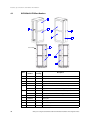
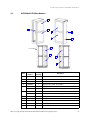


![Identifying Embeded Web Servers - [media.blackhat.com]](http://vs1.manualzilla.com/store/data/005833288_1-dd26f65aacb79f754f7b5aa134b8197a-150x150.png)