1
FILE NO.
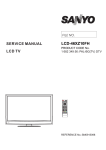
SERVICE MANUAL
LCD-37XR9DA(B)
LCD TV
PRODUCT CODE No.
1 682 348 98: CCIR DVB-T
REFERENCE No.:SM0915082
CONTENTS
Safety precautions………………………………………………………………………..… 1
Alignment instructions and method of software upgrading………………………………3
Working principle analysis of the unit……………………………….………….………….11
Block diagram…………………………………..………………………………….…………12
IC block diagram………………………………………………………………………..……13
Wiring diagram ……………………………………………………………………………. 18
Troubleshooting guide ………………………………………………………………..…… 19
Schematic diagram………………………………………………………………………… 24
APPENDIX-A: Assembly list
APPENDIX-B: Exploded View
Removing or Installing the Stand
Wall mounting instructions
Attention: This service manual is only for service personnel to take reference with. Before
servicing please read the following points carefully.
Safety precautions
1. Instructions
Be sure to switch off the power supply before replacing or welding any components or
inserting/plugging in connection wire Anti static measures to be taken (throughout the entire
production process!):
a) Do not touch here and there by hand at will;
b) Be sure to use anti static electric iron;
c) It’s a must for the welder to wear anti static gloves.
Please refer to the detailed list before replacing components that have special safety requirements.
Do not change the specs and type at will.
2. Points for attention in servicing of LCD
2.1 Screens are different from one model to another and therefore not interchangeable. Be sure to
use the screen of the original model for replacement.
2.2 The operation voltage of LCD screen is 700-825V. Be sure to take proper measures in
protecting yourself and the machine when testing the system in the course of normal operation or
right after the power is switched off. Please do not touch the circuit or the metal part of the module
that is in operation mode. Relevant operation is possible only one minute after the power is
switched off.
2.3 Do not use any adapter that is not identical with the TV set. Otherwise it will cause fire or
damage to the set.
2.4 Never operate the set or do any installation work in bad environment such as wet bathroom,
laundry, kitchen, or nearby fire source, heating equipment and devices or exposure to sunlight etc.
Otherwise bad effect will result.
2.5 If any foreign substance such as water, liquid, metal slices or other matters happens to fall into
the module, be sure to cut the power off immediately and do not move anything on the module lest it
should cause fire or electric shock due to contact with the high voltage or short circuit.
2.6 Should there be smoke, abnormal smell or sound from the module, please shut the power off at
once. Likewise, if the screen is not working after the power is on or in the course of operation, the
power must be cut off immediately and no more operation is allowed under the same condition.
2.7 Do not pull out or plug in the connection wire when the module is in operation or just after the
power is off because in this case relatively high voltage still remains in the capacitor of the driving
circuit. Please wait at least one minute before the pulling out or plugging in the connection wire.
2.8 When operating or installing LCD please don’t subject the LCD components to bending, twisting
or extrusion, collision lest mishap should result.
2.9 As most of the circuitry in LCD TV set is composed of CMOS integrated circuits, it’s necessary
to pay attention to anti statics. Before servicing LCD TV make sure to take anti static measure and
ensure full grounding for all the parts that have to be grounded.
2.10 There are lots of connection wires between parts behind the LCD screen. When servicing or
moving the set please take care not to touch or scratch them. Once they are damaged the screen
1
would be unable to work and no way to get it repaired.
If the connection wires, connections or components fixed by the thermotropic glue need to
disengage when service, please soak the thermotropic glue into the alcohol and then pull them out
in case of dagmage.
2.11 Special care must be taken in transporting or handling it. Exquisite shock vibration may lead to
breakage of screen glass or damage to driving circuit. Therefore it must be packed in a strong case
before the transportation or handling.
2.12 For the storage make sure to put it in a place where the environment can be controlled so as to
prevent the temperature and humidity from exceeding the limits as specified in the manual. For
prolonged storage, it is necessary to house it in an anti-moisture bag and put them altogether in one
place. The ambient conditions are tabulated as follows:
Temperature
Humidity
Scope for operation
0 ~ +50 oC
Scope for storage
-20 ~ +60 oC
Scope for operation
20% ~ 85%
Scope for storage
10% ~ 90%
2.13 Display of a fixed picture for a long time may result in appearance of picture residue on the
screen, as commonly called “ghost shadow”. The extent of the residual picture varies with the
maker of LCD screen. This phenomenon doesn’t represent failure. This “ghost shadow” may remain
in the picture for a period of time (several minutes). But when operating it please avoid displaying
still picture in high brightness for a long time.
3. Points for attention during installation
3.1 The front panel of LCD screen is of glass. When installing it please make sure to put it in place.
3.2 For service or installation it’s necessary to use specified screw lest it should damage the screen.
3.3 Be sure to take anti dust measures. Any foreign substance that happens to fall down between
the screen and the glass will affect the receiving and viewing effect
3.4 When dismantling or mounting the protective partition plate that is used for anti vibration and
insulation please take care to keep it in intactness so as to avoid hidden trouble.
3.5 Be sure to protect the cabinet from damage or scratch during service, dismantling or mounting.
2
Alignment instructions
1. Test equipment
VG-848 (YPbPr,VGA signal generator)
VG-849 (HDMI signal generator)
CA210 (white balancer)
2. Power test
Connect data processing board, power board and IR board according the wiring diagram, connect
the power and press “standby” button to turn on the TV.
a) Test the pin voltage of X808, the data is shown in table1:
Table1 voltage data of X808
X808
Voltage
Pin1
2
5.4~5.6
3.2~3.
V
4V
3
0
4,5
6,7
11.4~12.6
V
0
8
9
31.4~32.
4.85~5.35
6V
V
10
0
b) Test the pin voltage of XV03, the data is shown in table2:
Table2 voltage data of XV03
XV03
Pin1, 2
3, 4, 5
Voltage
23.8~25.2V
0
3. Alignment flow-chart
The alignment flow-chart is shown as fig-1
Check if DDC, HDCP KEY, FLASH are written
Combined test for general assembly
White balance adjustment
Connect to the center signal source and check each
function of TV (station leaking, analog control, etc.)
check the output of earphone and speaker.
3
11
4.85~5.
35V
12
0
13
>2.5V
Input AV/SVIDEO/SCART signal and check the function
Input HD signal and check the function of YPbPr
Input VGA signal and check if the display is normal, check
the function (analog control), horizontal/vertical center, etc.
Input HDMI signal and check if the display is normal, check
the function (analog control), horizontal/vertical center, etc.
Preset ex-factory
Check the accessories and packing
Fig-1 adjustment flow-chart
4. Adjustment instruction
4.1 Unit adjustments
4.1.1Connect all the boards according to wiring diagram, then power on and observe the display.
4.1.2 Method for entering factory menu:
a) Press “SOURCE”, “2”, “5”, ”8” and “0” in turn to enter factory menu;
b) Press “CH+” and “CH-” to move the cursor to the adjustment page of the level one factory menu,
then press ”OK” to enter;
c) Press “CH+” and “CH-” to move the cursor up and down;
d) Press “VOL-” and “VOL+” to adjust the item when the cursor move to a certain adjust item;
e) Press “MENU” to exit to the previous factory menu;
f) Press “EXIT” to exit the factory menu at any situation;
g) Press “OK” to enter the sub factory menu;
h) ADC ADJUST, ADC calibration of VGA, Component channel;
i) W/B ADJUST, white balance adjustment;
j) POWER Mode, set the turn-on modes. Standby---standby when power on; Mem---memory;
ForceOn---power on; ForceOn can be used for aging; set the “power mode” to “Standby” when
preset ex-factory unless the client appointed it;
k) ISP Mode, ON---soft upgrading through VGA port with ISP device, OFF---DDC function of VGA;
the setting will not be memory and will be “OFF” when power on again;
l) REST ALL, initialization of the factory and user data; after this item is confirm, the unit will
restart and display the guiding image.
m) Factory Data Reset, factory data initialization (including white balance adjustment, ADC
calibration and other adjusted data);
n) Factory Channel Preset, preset the factory channel; please connect to the center signal source
when operating; the present digital frequency is CH28 (529.5MHz), CH33 (564.5MHz) for
Australia and CH45 (666MHz) for UK, if the signal changes, perform “DTV manual search” in
4
“Channel” menu and the operation needs 15s or so.
o) MST Debug, the default is OFF. OFF---RS-232 should match the design criterion; ON--- it
should be convenient for using exploitation tool to adjust. The setting will not be memory and will
be “OFF” when power on again;
p) Backlight: adjust the backlight brightness, adjust the data and test the voltage of X804 pin2
(PWM), let the voltage to be the corresponding PWM voltage which the brightness is maximum.
It will be preset and doesn’t need adjust.
q) SSC Adjust, adjust the frequency spectrum expand, it will be preset and doesn’t need adjust.
r) AUDIO Curve, adjust the sound curve, it will be preset and doesn’t need adjust.
s) Picture Mode, set the picture values of each channel. Normally, they are preset and needn’t
adjust.
t) There is data in EEPROM after software upgrade, please perform Reset All before the first
adjustment.
4.2 ADC calibration
4.2.1ADC calibration in VGA channel
a) Switch to VGA channel.
b) Press” SOURCE”, then press “2, 5, 8, 0” in turn to enter the level one factory menu.
c) Move the cursor to “ADC ADJUST” and press OK to enter the sub-menu.
d) Input VGA signal (VG-848 Timing:856(1024x768/60Hz), Pattern:920 Gray 8 step(H)). Move the
cursor to “mode”, press CH+ and CH- to select “RGB”, move the cursor to “AUTO ADC” and
press OK to adjust automatically till complete.
4.2.2 ADC calibration in YPbPr channel
a) Switch to YPbPr channel.
b) Press” SOURCE”, then press “2, 5, 8, 0” in turn to enter the level one factory menu.
c) Move the cursor to “ADC ADJUST” and press OK to enter the sub-menu.
d) Input YPbPr signal (VG-848 Timing:978(483P), Pattern:984 SMPTE Color Bar). Move the
cursor to “mode”, press CH+ and CH- to select “YPbPr(HD)”, move the cursor to “AUTO ADC”
and press ENTER to adjust automatically till complete.
e) Input YPbPr signal (VG-848 Timing:978(483P), Pattern:984 SMPTE Color Bar). Move the
cursor to “mode”, press CH+ and CH- to select “YPbPr(SD)”, move the cursor to “AUTO ADC”
and press ENTER to adjust automatically till complete.
4.3 White balance adjustment
The default of color temperature of COOL is 12000K and the coordinate is (272, 278); color
temperature of NORMAL is 9300K and the coordinate is (285,293), color temperature of WARM is
6500K and the coordinate is (313,329).
4.3.1 Adjustment steps
Before the white balance adjustment, please let the unit working at least 30 minutes and at a
stable situation, use BBY channel of the white balancer CA-210.
a) Switch to HDMI channel;
b) Press” SOURCE”, then press “2, 5, 8, 0” in turn to enter the level one factory menu.
c) Move the cursor to “W/B ADJUST” and press OK to enter the sub-menu.
d) Input DVI/HDMI signal 1024X768/60Hz 16 step Gray (Timing:856, Pattern:921). Move the
cursor to “MODE”, press CH+ and CH- to select “HDMI” or other HDMI channel, move the
cursor to “TEMPERTURE” and press CH+ and CH- to select “COOL”.
e) Fix G GAIN, adjust R GAIN, B GAIN and let the color coordinate of the fourteenth scale be
5
(272,278).
f) Fix G OFFSET, adjust R OFFSET, B OFFSET and let the color coordinate of the third scale be
(272,278).
g) When adjusting, please keep the color temperature of high light to be X=272±5, Y=278±5 and
the low light to be X=272±8, Y=278±8.
h) Move the cursor to “COPY ALL” and copy the data to the other channels.
i) Check if the color temperatures of NORMAL and WARM are up to the mustard (low light
acceptable error:±8, high light acceptable error:±5), if not, adjust R-GAIN/ B-GAIN/ R-OFF/
B-OFF.
j) Check the color temperature of COOL, NORMAL and WARM of other channels (ANALOGTV,
DVB-T, Video, YPbPr,VGA), if they are not up to the mustard then adjust and store the data
separately.
k) The reference of adjustment rule is below:
B gun: lower B gun to increase X, Y coordinate data, while raise B gun to decrease the data.
R gun: raise R gun to increase X coordinate data, while lower R gun to decrease the data; (R
gun adjustment will affect X and Lv slightly).
G gun: raise G gun to increase Y coordinate data, while lower G gun to decrease the data; (G
gun adjustment will affect Y and Lv greatly).
5. Performance check
5.1 TV function
Connect RF to the center signal source, enter Channel menu → auto search, check if there are
channels be skipped, check if the picture and speaker are normal.
5.2 AV/S-Video terminals
Input AV/S-Video signal, check if the picture and sound are normal.
5.3 YPbPr/YcbCr terminal
Input YUV signal (VG848 signal generator), separately input the YUV signals listed in table3 and
check if the display and sound are normal at any situation (power on, channel switch and format
convert, etc.)
Table3 YUV signal format
No.
Resolution
H-frequecny
V-frequecny
Point clock pulse
(kHz)
(kHz)
frequecny (MHz)
Note
1
720X480
15.734
60
13.5
480i(NTSC)
2
720X480
15.734
59.94
13.5
480i(NTSC)
3
720X576
15.625
50
13.5
576i(PAL)
4
720X480
31.469
60
27
480p(NTSC PROG)
5
720X480
31.469
59.94
27
480p(NTSC PROG)
6
720X576
31.25
50
27
576p(PAL PROG)
7
1280X720
45
59.94
74.18
720p(59p)
8
1280X720
45
60
74.25
720p(60p)
9
1280X720
37.5
50
74.25
720p(50p)
10
1920X1080
33.75
59.94
74.25
1080i(59i)
11
1920X1080
33.75
60
74.25
1080i(60i)
12
1920X1080
28.125
50
74.25
1080i(50i)
6
13
1920X1080
67.5
59.94
148.35
1080p(59p)
14
1920X1080
67.5
60
148.5
1080p(60p)
15
1920X1080
56.25
50
148.5
1080p(50p)
16
1920X1080
-
23.94/24
-
-
17
1920X1080
-
25
-
-
18
1920X1080
-
29.97/30
-
-
5.4 VGA terminal
Input VGA signal (VG848 signal generator), separately input the signals listed in table4 and check
the display and sound. If the image is deflection of the Horizontal and vertical, select
Picture->Screen->Auto Adjusting to perform auto-correct.
Table4 VGA signal format
No.
H-frequecny
Resolution
(kHz)
Point clock pulse
V-frequecny (kHz)
Note
frequecny (MHz)
1
640X480
31.469
59.94
25.175
IBM
2
720X400
31.469
70.086
28.322
IBM
3
640X480
37.861
72.809
31.5
VESA
4
640X480
37.5
75
31.5
VESA
5
800X600
35.156
56.25
36
VESA
6
800X600
37.879
60.317
40
VESA
7
800X600
48.077
72.188
50
VESA
8
800X600
46.875
75
49.5
VESA
9
1024X768
48.363
60.004
65
VESA
10
1024X768
56.476
70.069
75
VESA
11
1024X768
60.023
75.029
78.75
VESA
12
1152X864
67.5
75
108
VESA
13
1280X960
60
60
108
VESA
14
1280X1024
63.98
60.02
108
VESA
15
1280X1024
80
75
135
SXGA
16
1440X900
-
60
-
-
17
1680X1050
-
60
-
-
18
1360X768
47.7
60
85.5
-
5.5 HDMI terminal
Input HDMI signal (VG849 signal generator), separately input the signals listed in table4 and table5
and check the display and sound (32KHz, 44.1KHz, 48KHz) at any situation (power on, channel
switch and format convert, etc.)
5.6 other functions check
a) Check the turn on/turn off timer, sleep timer, picture/sound mode, OSD, stereo and digital sound
port, etc.
b) Check the digital program, if Audio Only is normal.
c) Check MHEG function of the digital program for UK unit.
d) Check if “CI: Common Interface” is normal.
e) Check logical channel number (LCN) for Australia.
7
f) Check logical channel number (LCN) for France, UK and Italy.
g) Check OTA function for Australia special custom.
6. Presetting before ex-factory
Enter user menu LOCK page, select “Restore Factory Default” to preset the ex-factory.
a) Clear the program information.
b) Clear VCHIP, parental control, etc.
c) Set the default data of user menu.
d) Set Menu Language to English.
e) Set Power on Mode to Off.
7. Software instruction
Table5 software instruction
No.
Code No.
Type
Function
written before
Method
paste
Yes
N810
5272532003
EN25B32-100HIP
FLASH
N807
5272404002
AT24C04
HDMI KEY
Yes
NA03
5272402002
AT24C02
HDMI EDID
Yes
NA04
5272402002
AT24C02
HDMI EDID
NA08
5272402002
AT24C02
N107
5272421002
AT24LC21A
HDMI
Written with device like ALL11,
write-protect, refer to note1.
Written with device like ALL11
Yes
EDID
Yes
(Australia only)
Yes
VGA EDID
Note1: write-protect setting: enter ALL-100 interface, select Config and press “config setting”, set
Protect to “All Protect”, select “config” when writing. The “write-protect” will be set again when
ALL-100 program restart.
Note2: software writing and upgrade method with ISP writing-device
(1)
Main board upgrade: connect a four-pin wire of the ISP writing-device to Debug port(X806)
on the main board; Unit upgrade: connect VGA ports of the ISP writing-device and the main
board, enter factory menu and set “ISP Mode” to “ON”.
(2)
Using Mstar writing-tool on line, click “Connect” menu, if it displays “Device EN25B32“ as
shown in fig2, the connection is success, if it fails, select “EN25B52” of “Device” manually
and press “Connect” again.
8
Fig2 Device EN25B52 successful connection
(3)
Click “Read” and select the file written (MERGE.bin for example) as shown in fig3.
(4)
Fig3 the written file
Click “Auto”, select “All chip” , “program” and other items as shown if fig4.
Fig4 selected items
(5)
(6)
Press “Run” in fig4 to begin writing and there are two steps: Erase and Program.
If the process of writing succeeds, it will display “Pass” near “Run” as shown in fig5.
9
(7)
Fig5
Repeat step 2) and 5) to write the program to the other units without exit the ISP interface.
Note3: software writing and upgrade method with USB port
(1)
Make sure the USB device is formatted as FAT32.
(2)
Copy the program named Merge.bin to USB device.
(3)
Insert the USB device to USB port of the unit, power on and select RF-ATV channel, begin
USB upgrade after OSD disappear. It will display blue when read the data from USB device,
while display red when write Flash. The flash must be pull out when display red. It will flicker
in red and blue if the process of writing is abnormal.
(4)
The method are not applicable to all the USB devices, try another one if a certain USB device
is inapplicable.
10
Working principle analysis of the unit
1. PAL/SECAM signal flow:
Antenna reception PAL/SECAM signal will be send to tuner TDA1616, which contains frequency
turning, HF and IF amplifier circuit and is controlled by master control IC MSD109 (comprises CPU)
through I2C bus. The analog IF signal via intermediate frequency amplifying, video SAW filter
K3953 and audio SAW filter K9656 to input to analog demodulate IC (IF) R2A10406NP, after
demodulating and output standard video signal TV-CVBS and sound IF signal (SIF).
TV-CVBS will send to the master control IC MSD109 to video decode, deinterlace and scale, then
output LVDS level drive for panel display.
The sound IF (SIF) will be fed into MSD109, after demodulating, pre-amplifying, bass adjusting and
volume control, the sound signal will separate into L/R channels and input to earphone amplifier
BH3547F amplifying, then output two ways. One way will be sent to earphone, another will be sent
to digital sound amplifier R2A15112FP amplifying then sent to speaker.
2. DVB-T signal flow:
Antenna reception DVB-T signal will be sent to tuner TDA1616, after frequency tuning, HF
amplification, IF amplification and SAW FILTER, output IF signal to demodulation chip CE6353, via
QAM demodulation, fed to MSD109 for information source decoding in the format of standard serial
TS stream.
HD video signal via decoding to A/D conversion and OSD superposition, at last output LVDS drive
level for panel display.
HD audio signal via decoder built-in MSD109, resumed to multi- channel sound of Dolby AC-3. The
audio signal will be sent to back end to perform bass adjustment and volume control, then it will
separate into L/R channels and input to earphone amplifier BH3547F amplifying, then output two
ways. One way will be sent to earphone, another way will be sent to digital sound amplifier
R2A15112FP amplifying then sent to speaker.
3. AV/SV signal flow
SV signal and the first path AV signal switch automatically via S-terminal socket, the signal and the
second path AV signal will be fed to MSD109 to perform video decode, deinterlace and scale, then
output LVDS drive level for panel display.
Audio signal from AV/SV via matched resistance is fed to external audio switch HEF4052 to switch,
then it is directly sent to MSD109 to bass adjust and volume control, the sound will separate into L/R
channels and input to earphone amplifier BH3547F amplifying, then output two ways. One way will
be sent to earphone, another way will be sent to digital sound amplifier R2A15112FP amplifying
then sent to speaker.
4. PC/YPrPb signal flow
PC and the second path YPbPr signal are switched via external switcher PI5V330, then the signal
and the first path YPbPr signal will be sent to MSD109 A/D conversion, output R/G/B of 24 bit to
back end module to digital decode, image scale and OSD superposition, then send to LVDS level
drive for panel display.
Sound signal of PC/YPrPb via matched resistance and a-c couple are sent to MSD109 to bass
adjust and volume control, the sound will separate into L/R channels and input to earphone
11
amplifier BH3547F amplifying, then output two ways. One way will be sent to earphone, another
way will be sent to digital sound amplifier R2A15112FP amplifying then sent to speaker.
5. HDMI signal flow
Three HDMI video signals via switcher PS321 are directly fed to the master control IC MSD109 to
digital decode, image scale and OSD superposition, then output LVDS drive level for panel display.
HDMI audio signal via decoder built-in MSD109 is fed to back end to bass adjust and volume
control, the sound will separate into L/R channels and input to earphone amplifier BH3547F
amplifying, then output two ways. One way will be sent to earphone, another way will be sent to
digital sound amplifier R2A15112FP amplifying then sent to speaker.
Block diagram
12
IC block diagram
1. MSD109CL
Twin-turbo 8051 MCU
Supports multi-path TS stream input
Two paths TS stream output, integrated switch selection
Supports both serial and parallel TS stream input
Maximum TS data rate is 104Mbps for serial or 13MB/sec for parallel
MPEG-2 audio decoder
MPEG-1, MPEG-2 (Layer I/II) and Dolby1 Digital(AC-3) audio decoder
MPEG-4 decoder
NTSC/PAL/SECAM video decoder
Supports NTSC-M, NTSC-J, NTSC-4.43, PAL (B,D,G,H,M,N,I,), and SECAM
Multi-standard sound processor
Supports BTSC/A2/EIA-J demodulation in NTSC and A2/NICAM/FM/AM demodulation in PAL
Supports MTS Mode MONO/STEREO/SAP in BTSC/EIA-J and MONO/STEREO/DUAL in
A2/NICAM
Digital Audio Interface
Analog RGB Compliant/YUV input Ports
Two analog ports support up to 1080P
Supports PC RGB input up to SXGA@75Hz
Supports HDTV RGB/YPbPr/YCbCr
Supports Composite Sync and SOG (Sync-on-Green) separator
Automatic color calibration
DVI/HDCP/HDMI input ports
Supports up to 225MHz @ 1080P 60Hz with 12-bit deep-color resolution
High-bandwidth Digital Content Protection (HDCP) 1.1 compliant receiver
High Definition Multimedia Interface (HDMI) 1.3 compliant receiver with CEC (Consumer
Electronics Control) support
Video Processing & Conversion
3-D motion adaptive video de-interlacers with edge-oriented adaptive algorithm for smooth
low-angle edges
Automatic 3:2 pull-down & 2:2 pull-down detection and recovery
10-bit internal data processing
3-D video noise reduction
Output Interface
Supports up to 10-bit dual LVDS full-HD (1920 x 1080) panel interface
Video output port
Supports CVBS/S-video bypass output
Built-in video encoder for encoding digital video into CVBS output
Miscellaneous
Supports DVB-CI port conditional receiver
USB 2.0 port can be connected to the external equipment for software upgrading
13
2. CE6353
The chip comprises 8MHz bandwidth SAW and supports demodulation of 6MHz, 7MHz and 8MHz,
2K/8K carrier and supports both serial and parallel TS stream output.
3. R2A10406NP
*VIF frequency corresponds to 38.9MHz.
*SIF frequency corresponds to M/N,B/G,I,D/K and SECAM L,L'.
*I2CBUS control.
14
4. PS321
The chip supports both I2C control and I/O control mode; supports both internal and external EDIT.
5. R2A15112FP
15
6. TDA1616
16
17
Wiring diagram
18
Trouble shooting
1. Fault clearance
Before servicing please check to find the possible causes of the troubles according to the table
below.
1.1 Antenna (signal):
Picture is out of focus or jumping
Bad status in signal receiving
Poor signal
Check if there are failures with the electrical connector or
the antenna.
Check if the antenna is properly connected.
Fringe in picture
Check if the antenna is correctly oriented.
Maybe there is electric wave reflected from hilltop or
building.
Picture is interfered by stripe
Possibly due to interference from automobile, train, high
shaped bright spots
voltage transmission line, neon lamp etc.
Maybe there is interference between antenna and power
supply line. Please try to separate them in a longer
distance.
Maybe the shielded-layer of signal wire is not connected
properly to the connector.
There appear streaks or light color
Check if interfered by other equipment and if interfered
on the screen
possibly by the equipment like transmitting antenna,
non-professional radio station and cellular phone.
1.2 TV set:
Symptoms
Unable to switch the power on
No picture and sound
Deterioration of color phase or
color tone
Screen position or size is not
proper
Picture is twisted and deformed
Picture color changed or colorless
Possible cause
Check to see if the power plug has been inserted
properly into the socket.
Check to see if the power supply of liquid crystal TV has
been switched on. (As can be indicated by the red LED
at the front of the TV set)
See if it’s receiving the signal that is transmitted from
other source than the station
Check if it’s connected to the wrong terminal or if the
input mode is correct.
Check if the signal cable connection between video
frequency source and the liquid crystal TV set is correct.
Check if all the picture setups have been corrected.
Check is the screen position and size is correctly set up.
Check to see if the picture-frame ratio is properly set up.
Check the “Component” or “RGB” settings of the liquid
19
Picture too bright and there is
distortion in the brightest area
Picture is whitish or too bright in
the darkest area of the picture
No picture or signal produced from
the displayer if “XXX in search”
appears.
There appears an indication “outside the receivable scope)
Remote control cannot work
properly
No picture and sound, but only
hash.
Blur picture
No sound
When playing VHS picture search
tape, there are lines at the top or
bottom of the picture.
crystal TV set and make proper adjustment according to
the signal types.
Check if the contrast setting is too high.
Possibly the output quality of DVD broadcaster is set too
high.
It maybe also due to improper terminal connection of the
video frequency signal in a certain position of the
system.
Check if the setting for the brightness is too high
Possibly the brightness grade of DVD player
(broadcaster) is set too high.
Check if the cable is disconnected.
Check if it’s connected to the proper terminal or if the
input mode is correct.
Check if the TV set can receive input signal. The signal is
not correctly identified and VGA format is beyond the
specified scope.
Check if the batteries are installed in the reverse order.
Check if the battery is effective.
Check the distance or angle from the monitor.
Check if there is any obstruct between the remote control
and the TV set.
Check if the remote control signal- receiving window is
exposed to strong fluorescence.
Check if the antenna cable is correctly connected, or if it
has received the video signal correctly.
Check if the antenna cable is correctly connected.
Of if it has received the right video signal.
Check if the “mute” audio frequency setting is selected.
Check if the sound volume is set to minimum.
Make sure the earphone is not connected.
Check if the cable connection is loose.
When being played or in pause VHS picture search tape
sometimes can’t provide stable picture, which may lead
to incorrect display of the liquid crystal TV, In this case
please press “auto” key on the remote control so as to
enable the liquid crystal TV set to recheck the signal and
then to display correct picture signal
20
2. Troubleshooting guide
2.1. No raster
Turn-on power supply, check
if the red indicator is light in
the STANDBY?
yes
no
Check if 5VSTB of X808 11#
on main board is normal?
Press POWER button on the
unit or sensor control and
check the indicator.
red
blue
no
Check if the PIN1 of X808 on
main board is high-level?
Check STANDBY circuit of
power supply board
yes
no
Check power board and
back light board
Check if the PIN13 of X808 on
main board is high-level?
Check the backlight
control circuit on the
main board
yes
Check power
supply board
21
2.2. Backlight, but no picture
Check if the unit button
and remote control
operation?
no
yes
Does display OSD
menu on screen when
press menu button?
no
yes
yes
Check if all channels
have no signal?
no
no
Enter
factory-menu,
initialization EEPROM,
then turn off the TV,
turn on again, display
picture?
Replace main
board
yes
Replace
main board
Adjust main board
again
22
2.3 Picture, but no sound
Check if NV02 pin4,
5, 32, 33 are 24V?
no
Check 24V power
supply of power
board and the path
between XV03 and
NV02 on main board
yes
Check if NV02
pin10, 27 are high
voltage?
yes
no
Is there sound in
earphone?
yes
Replace
NV02
no
If NS01 pin126, 148
are low voltage?
Is there sound when
touch CV04, CV05
with probe?
no
Check the path
between NS01 pin
126,148
and
NV02 pin10, 27
Check earphone
amplify circuit
Replace NS01
23
yes
Check
the
audio output
circuit of the
main IC
L104
STBL2012-501
+32V
+5V
R128
7
GND-A
R101
0
R102
100
TV_IF_AGC
IF-gain
9
TV_FAT_IFN
IF-out10
10
V101
2SC2216
C109
10n
R105
1K
IF-out11
C110
10n
R109
6.8K
R110
10K
R108
6.8K
D101
MA859
V102
BC847AW
R112
3.3K
R111
22K
R113
100K
GND-A
C101
10n
24
23
R107
56
GND-A
TV_FAT_IFP
+5V
22
29
6
5
4
7
IFAGC1
VCOF/B
SIFIN2
SIFIN1
PORT1
C112
10n
GND-A
RFAGCOUT
REFINPUT
100
10n
11 C124
220n
2
3
4
5
C113
10n
Z101
K9656
R114
6.8K
L102
STBL2012-501
R115
330
GND-A
+5V
22uH
GND-D
GND-D
TV_SIFM
002:C4
+5V_TUNER
N100
FSA4159
13
G101
14
C127
1
20p
B1
S
2
GND
GND-A
RF_AGC_SCL#
Vcc
4
B0
R121
6.8K
R123
82K
C131
100n
5
3
GND-A
R130
1K
6
RF_AGC
+5V_TUNER
A
T_RF_AGC GND-A
R122
10K
RF_AGC
GND-A
0
R127
C128
10u
16V
C129
100n
GND-A
R116
R117
C116
220u
10V
TV_CVBS
003:E2
R133
75
12 C12550V 100n
4MHz
C122
10n
L108
L103
STBL2012-501
GND-A
100
100
SDA 007:A4
SCL 007:A4
C121
10n
GND-A
+3.3V_DE
+1.8V_PDE
21
26
22
62
PLLVdd
PLL1TEST
PLLGnd
BKERR
11
STATUS
8.2K
RJ23 GND-D
RJ26
RJ27
100n
CJ27
100n
CJ24
100n
CJ26
100n
CJ22
100n
CJ20
100n
CJ14
100n
CJ21
100n
CJ19
4.7u
CJ12
LJ03
GND-D
100
100
SDA 007:A4
SCL 007:A4
+3.3V_DE
1
3
8
14
20
25
38
40
46
55
60
Vss
Vss
Vss
Vss
Vss
Vss
Vss
Vss
Vss
Vss
Vss
OSCMODE
0
RJ09
27
XTI
RJ22
+1.8V_ADE
6
5
DATA1
4
CLK1
9
RESET
CLK2/GPP0
DATA2/GPP1
XTO
35
36
IRQ
23
RJ02
GPP3
24
RJ01
100
43
RJ20 +3.3V_DE
RJ21
GND-D
+1.8V_DE
GND-D
RJ08
2.2M
RST_6353
002:A5
GND-D
GJ01
20.48MHz
GND-D
33p
CJ07
100
TUNER_SDA
SLEEP
GND-D
33p
CJ06
TUNER_SCL
4.7K
RJ04
10
4.7K
4.7K
0
100n
CJ17
GND-A
33
RJ16
RJ17
RJ18
RJ19
GND-D
+1.8V_CORE
LJ02
100n
CJ18
GND-A
33
33
33
33
33
+1.8V_DE
100n
CJ15
+1.8V_PDE
GND-A
+3.3V_DE
RJ25
TS_SCLK
TS_SDATA
TS_MICLK
TS_MDI[0]
TS_MDI[1]
TS_MDI[2]
TS_MDI[3]
TS_MDI[4]
TS_MDI[5]
TS_MDI[6]
TS_MDI[7]
TS_MIVAL
TS_MISTRT
TS_SVAL
TS_SSTRT
4.7u
CJ13
NJ01
CE6353
RJ24
RJ13
RJ14
RJ15
100n
CJ16
RJ06
1K
MOCLK
MDO0
MDO1
MDO2
MDO3
MDO4
MDO5
MDO6
MDO7
MOVAL
MOSTRT
61
49
50
51
52
53
56
57
58
48
47
33
33
33
RJ29
10K
100n
CJ03
TV_IF_AGC
AGC1
AGC2/GPP2
AVdd
AGnd
AGnd
Vdd33
RFLEV
63
100n
CJ09
42
41
28
29
32
33
34
1K
RJ07
RJ05
10K
VIN
+3.3V_DE +1.8V_ADE
2.2u
CJ11
GND-D
GND-D
31
+5V
10p
CJ35
GND-D
MICLK
10p
CJ37
44
12
15
16
17
18
SADD4
SADD3
SADD2
SADD1
SADD0
VIN
TV_FAT_IFN
RJ12
0
10p
CJ36
30
SMTEST
GND-A
CJ02
100n
CVdd
CVdd
CVdd
CVdd
CVdd
CVdd
Vdd
Vdd
Vdd
Vdd
7
19
37
39
59
64
2
13
45
54
22p
CJ04
330nH
LJ05
22p
CJ05
51P
CJ99
RJ31
220
10p
CJ34
GND-D
TV_FAT_IFP
RJ28
10K
GND-D
15p
CJ10
+1.8V_CORE
15p
CJ08
+3.3V_DE
CJ01
100n
RJ30
220
RJ11
10K
100n
CJ25
+3.3V_DE
LJ01
RJ10
10K
100n
CJ23
+1.8V_DE
4.7K
RJ03
GND-A
C117
220n
C115
100n
R132
75
16V
GND-D
RF_AGC
1
L101
STBL2012-501
R129
220
GND-D
GND-A
C114
1u
50V
R126
5.6K
GND-D
C132
V104
100u
BC847AW
TV_SIFP
002:C4
GND-A
R120
0
10 C123
R125
5.6K
10V
GND
GND
EQF/B
NC
3
2
N101
R2A10406NP
GND
GND-A
12
RFAGCDELAY
VIFIN1
9 R118
IFAGC2
25
8
15
26
SDA
C111 GND-A
10n
C130
100u
GND-A
2.2u R119
10K
16V
C126
SIFOUT
16
R106
390
0
VIFIN2
R124
220
AUDIOOUT
SCL
R104
5.6K
C108
10n
PORT2
17
28
5
VIDEOOUT
4
Vcc
6
+5V
GND12
3
18
C107
1000u
10V
5
4MHz
8
13
2
27
L107
TD1616EF/PHP-5
TUNER_SDA
SDA
IF-out8
GND13
1
1.2uH
APCFILTER
R103
75
TUNER_SCL
4
19
3
SCL
AUDIOF/B
Z102
K3953
ANT-pwr
AFCFILTER
2
11
SIFMIXF/B
+9V
0.56uH
L106
53822B56K3
TUNER1
GND-A
T_RF_AGC
20
T_RF_AGC
21
1
+5V
100n
10n
470n
V103
BC847AW
Vtune
RF-gain
100n
C229
C118
C119
C120
4.7K
R131
22uH
1
14
C106
470u
10V
DE-EMPHASIS
C105
100n
L116
BG2012D151T
100n
C230
+5V_TUNER
L105
AFTOUT
C103
10n
RF_AGC_SCL#
GND15
15
GND-A
GND14
+9V
C104
22u
50V
C102
82n
GND-D
GND-D
GND-D
TUNER+IF
X106
JY-3541L-01-030
R135
10K
VGA_LIN
VGA_RIN
+3.3V_VD
33
VGA_VSYNC
003:D3
5
GND-D
B1
L111
BG2012D151T
R195
10K
SC2_LOUT
Z107
470MHz
GND-D
C176
2.2u
V107
MMBT3904
GND-D
AV_OUTL
N102
PESD5V0L5UY
GND-D
AV_CVBSOUT
AV_CVBSOUT
R190
GND-D
10K
AV_OUTL
C147
47p
GND-D
R155
10K
GND-D
AV_OUTR
R2
1
4
3
2
C183
2.2u
100K
R218
1n
C190
GND-D
C160
100n
47
R214
C136
47p
4.7u
C180
16V
R213
4.7K
V110
MMBT3904
R206
8.2K
12K
R140
YUV1_RIN
GND-D
GND-D
R205
47K
R198
10K
SC2_ROUT
R137
10K
C186
100n
5
C158
47p
GND-D
12K
R156
AV_OUTR
L114
BG2012D151T
N105
PESD5V0L4UG
+9V
1
R1
C192
47p
12K
R221
C191
47p
B2
VGA_R_IN
003:C4
R223
10K
AV_RIN
AV_RIN
C177
100n
12K
R219
VGA_G_IN
003:C4
1 2 3
R1
2
+9V
VGA_B_IN
003:C4
GND-D
X108
HJR-413/PB-1
GND-D
AV_LIN
6 5 4
GND-D
R222
10K
AV_LIN
VCLK: 0=READ ONLY
R189
75
Z106
470MHz
R149
0
R142 75
BC847AW
V115
12K
R154
1
V114
BC847AW
X107
AV13-06-526
AV_INPUT
AV_INPUT
G1
SDA
GND-D
TXD_UPDATE
007:D5
R181
0
Z104
470MHz
R147
0
R150 75
6
VSS
4
Z105
R148470MHz
0
R139 75
11
R277
33
1n
C187
2
SCL
100K
R215
7
NC3
16V
12
R274
510
R185
4.7K
4.7u
C175
3
R182
4.7K
R207
4.7K
8
R180
4.7K
6
R202
0
Z103
470MHz
C159
100n
7
3
47
R208
13
R161
2.2K
R199
47K
4
VCLK
C145
100n
R276
200
ISP_EN
R200
8.2K
9
VCC
NC2
R273
510
V113
BC847AW
G2
R146
2.2K
R201
0
14
8
NC1
2
GND-D
5
1
+5V
C135
100n
R275
10K
R272
33
5
1 2 3
X105
HC1038-15F-3.08
10
D102
MMBD1204
N107
24LC21A/SN
33
VCC-VGA
N104
PESD5V0L5UY
R163
6 5 4
GND-D
15
RXD_UPDATE
007:D5
+5V VCC-VGA
3
VGA_HSYNC
003:D3
4
33
N103
PESD5V0L4UG
R165
1
R164
C144
47p
R162
C140
47p
12K
R160
12K
R141
G
R153
75
R136
10K
R
33
L
GND-D
3
GND-D
GND-D
1u
C157
100n
GND-D
SPDIF-OUT
Y2_INPUT
0
C164
2.2n
0
G1
GND-D
R179
R183
75
PRIM_AUD_OUT_R
008:C4
C166
2.2n
C161
100p
GND-D
R169
R178
75
GND-D
R188
13K
GND-D
R167
006:G5
PANEL_ON/OFF
PRIM_AUD_OUT_L
008:C4
Pr2_INPUT
0
GND-D
R184
R186
75
5 4 3 1
N108
+5V
GND-D
GND-D
PESD5V0L4UG 2
C171
100n
R171
10K
GND-D
200
GND-D
120
R271
R170
100n
C231
D103
PWR_ON/OFF
005:B2
I2C0_DATA
006:F2
I2C0_CLK
006:F2
0
R168
75
Pb2_INPUT
B
BLK_ON
005:C5
RST_6353
001:F6
GND-D
003:C2
Pr1_INPUT
SPDIFI
SPDIFO
GND-D
GND-D
R159
R166
75
B1
GND-D
+3.3V_VD
0
ISP_EN
EEP_W_EN
007:A1
I2S_IN_BCK
I2S_IN_WS
I2S_IN_SD
224
232
C170
2.2n
003:C2
Pb1_INPUT
AUVRM
AUVRP
AUVAG
AUCOM
222
221
223
C169
2.2n
R1
67
68
69
65
225
230
226
231
233
R158
75
100
100
X109
HJR-613/PB-1
R157
G2
63
64
4.7u
C152
C151
4.7u
C146
100n
C148
L109
SGMI2012M1R0KT
3
2
1
GND-D
I2S_OUT_MCK
AUL2
I2S_OUT_BCK
AUR2
I2S_OUT_WS
I2S_OUT_SD
AUL3 I2S_OUT_MUTE/CEC
AUR3
003:C2
Y1_INPUT
0
B2
1u
1u
AUL1
AUR1
61
62
SC2_LOUT
SC2_ROUT
R2
1u
1u
100
100
C162
100p
59
60
R174
R175
100
R172
100
R173
R176
R177
C163
100p
C142
C143
AUL0
AUR0
71
72
73
74
75
76
C165
100p
1u
1u
C155
C156
AV_LIN
AV_RIN
57
58
N109
PESD5V0L5UY
C141
100n
PESD5V0L4UG
N106
AUOUTL2
AUOUTR2
AUOUTL1
AUOUTR1
AUOUTL0
AUOUTR0
R194
13K
1u
1u
SIF1P
SIF1M
1 3 4 5
C167
100p
C139
47p
VGA_LIN
VGA_RIN
GND-D
GND-D
C178
C179
C149
C150
YUV2_LIN
100n
C154
TV_SIFM
001:F2
YUV2_LIN
YUV2_RIN
YUV1_LIN
YUV1_RIN
GND-D
12K
R152
4
5
6
YUV2_RIN
C138
47p
53
54
R193
13K
12K
R145
GND-D
C173
2.2u
C174
2.2u
100n
C168
100p
C153
R191
1K
12K
R143
4
2
R2
6
L2
5
R151
10K
2
C137
47p
TV_SIFP
001:F2
R144
10K
C172
GND-D 100n
NS01
MSD109CL-H
YUV1_LIN
R187
13K
L1
GND-D
R138
10K
HJR-03A-OR
X110
GND-D
AUDIO IN/OUT
NS01
MSD109CL-H
Pb1_INPUT
003:B3
Y1_INPUT
002:B3
Pr1_INPUT
003:B3
C204
C205
C206
C207
47n
1n
47n
47n
24
25
26
27
R231
R232
R233
R234
47
470
47
47
C208
C209
C210
C211
47n
1n
47n
47n
29
32
31
34
R235
R236
R237
47
47
47
C212
C213
C214
47n
47n
47n
28
30
33
BIN1P
SOGIN1
GIN1P
RIN1P
BIN0P
SOGIN0
GIN0P
RIN0P
BINM
GINM
RINM
CVBS0
CVBS1
CVBS2
CVBS3
CVBS4
CVBS5
CVBS6
CVBS7
CVBSOUT
VCOM0
VCOM1
47
45
44
43
42
40
41
39
50
48
46
100n
100n
100n
100n
100n
C220
C221
C222
C223
C224
100n
C225
47n
47n
C218
TV_CVBS
001:H2
AV_INPUT
C226 47
R260
21
22
23
16
100n
19
20
37
38
002:C1 VGA_HSYNC
002:C1 VGA_VSYNC
HSYNC1
VSYNC1
HSYNC0
VSYNC0
GND-D
GND-D
MMBT3906LT1
V112
V111
MMBT3904
R262
75 AV_CVBSOUT
A
R250
390 1%
R259
390
AV_CVBSOUT
R258
120
R256
15K
+3.3V_DVI
VCLAMP
REFP
REFM
REXT
C227
2.2u
C215
R257
470
100n
100n
100n
C216
2.2u
C201
C202
C203
R255
30K
+5V
GND-D
R261
47
100n
C228
RGB1_BIN
RGB1_SOGIN
RGB1_GIN
RGB1_RIN
AV_CVBSOUT
GND-D
+5V_PI
+5V
+5V_PI
VGA_G_IN
002:B2
Y2_INPUT
VGA_B_IN
002:B2
Pb2_INPUT
C195
2.2u
3
C196
2.2u
2
C197
2.2u
6
C198
2.2u
5
GND-D
16
S2A
VCC
S1A
DA
4
100n
C219
33K
33K
33K
33K
33K
33K
100u
C217
R238
R240
R242
R244
R246
R248
L115
STPB2012-201PT
RGB1_GIN
RGB1_SOGIN
R251
47
R252
470
7
R253
47
RGB1_BIN
9
R254
47
RGB1_RIN
S2B
S1B
DB
N110
C199
2.2u
10
C200
2.2u
11
S2C
S1C
PI5V330
DC
14
R239
R241
R243
R245
R247
R249
S1D
13
12
S2D
DD
15
EN
33K
33K
33K
33K
33K
33K
VGA_R_IN
002:B2
Pr2_INPUT
8
1
GND
IN
4052_SEL
007:C4
GND-D
GND-D
VIDEO IN/OUT
+2.5V_DDR
+2.5V_ADDR
RS02
1K
235
MADR0
MADR1
MADR2
MADR3
MADR4
MADR5
MADR6
MADR7
MADR8
MADR9
MADR10
MADR11
MADR12
MCLKZ
MCLK
MCLKE
BADR1
BADA0
WEZ
RASZ
CASZ
MVREF
C
240
241
242
243
244
245
246
248
249
250
251
252
253
254
255
256
257
258
MADR0
MADR1
MADR2
MADR3
MADR4
MADR5
MADR6
MADR7
MADR8
MADR9
MADR10
MADR11
MCLKMCLK+
CKE
BA1
BA0
WEZ
RASZ
CASZ
1%
45
46
44
MCLK+
MCLKCKE
23
22
21
24
RASZM0
CASZM0
M1_WEZ
56
56
22
22
DQM1
DQM0
DQS1
DQS0
CK
CK
CKE
RS10
RS11
RS12
RS13
GND-D
RAS
CAS
WE
CS
20
LDM
47
UDM
16
LDQS
51
UDQS
56
MADR8
MADR9
MADR10
MADR11
MADR4
MADR5
MADR6
MADR7
MADR3
MADR2
MADR1
MADR0
RS05
M1_MADR8
M1_MADR0
M1_MADR1
M1_MADR2
M1_MADR3
M1_MADR4
M1_MADR5
M1_MADR6
M1_MADR7
M1_MADR8
M1_MADR9
M1_MADR10
M1_MADR11
M1_MADR9
M1_MADR10
M1_MADR11
M1_MADR4
M1_MADR5
M1_MADR6
M1_MADR7
M1_MADR3
M1_MADR2
M1_MADR1
M1_MADR0
RS06
56
56
RS03
MADR12
56
WEZ
CASZ
RASZ
BA0
1%
BA1
RS07
RS04
56
56
M1_WEZ
CASZM0
RASZM0
M1-BA0
RS15
M1-BA0
M1-BA1
29
30
31
32
35
36
37
38
39
40
28
41
42
17
26
27
A0
A1
A2
A3
A4
A5
A6
A7
A8
A9
A10/AP
A11
A12
NC17
BA0
BA1
RS34
1K
CS25
100n
2
DQ0
4
DQ1
5
DQ2
7
DQ3
8
DQ4 10
RS18
DQ5
11
DQ6
13
DQ7
54
DQ8
56
DQ9 57
RS19
DQ10
59
DQ11
60
DQ12
62
DQ13
63
DQ14
65
DQ15
VSS34
VSS48
VSS66
VSSQ6
VSSQ12
VSSQ52
VSSQ58
VSSQ64
RS17
22
CKE
MDATA15
MDATA14
MDATA13
MDATA12
MDATA11
MDATA10
MDATA9
MDATA8
MDATA7
MDATA6
MDATA5
MDATA4
MDATA3
MDATA2
MDATA1
MDATA0
22
22
DQM3
DQM2
DQS3
DQS2
GND-D
1%
23
22
21
24
RS25
56
56
RS21
RS22
MADR12
GND-D
M1-BA1
56
RS26
WEZ
CASZ
RASZ
BA0
RS23
BA1
RS29
RS30
RS31
RS32
56
56
22
22
56
56
M0_MADR0
M0_MADR1
M0_MADR2
M0_MADR3
M0_MADR4
M0_MADR5
M0_MADR6
M0_MADR7
M0_MADR8
M0_MADR9
M0_MADR10
M0_MADR11
M0_MADR12
M0_MADR12
M0_WEZ
M0_CASZ
RASZD
BA0D
VREF
CK
CK
CKE
1
18
33
3
9
15
55
61
56
56
M0_MADR11
M0_MADR10
M0_MADR9
M0_MADR8
M0_MADR7
M0_MADR6
M0_MADR5
M0_MADR4
M0_MADR0
M0_MADR1
M0_MADR2
M0_MADR3
45
46
44
VDD1
VDD18
VDD33
VDDQ3
VDDQ9
VDDQ15
VDDQ55
VDDQ61
BA0D
BA1D
GND-D
20
47
16
51
29
30
31
32
35
36
37
38
39
40
28
41
42
17
26
27
RAS
CAS
WE
CS
LDM
UDM
LDQS
UDQS
A0
A1
A2
A3
A4
A5
A6
A7
A8
A9
A10/AP
A11
A12
NC17
BA0
BA1
2
DQ0
4
DQ1
5
DQ2
7
DQ3
8
DQ4
10
DQ5
11 RS37
DQ6
13
DQ7
54
DQ8
56
DQ9
57 RS38
DQ10
59
DQ11
60
DQ12
62
DQ13
63
DQ14
65
DQ15
VSS34
VSS48
VSS66
VSSQ6
VSSQ12
VSSQ52
VSSQ58
VSSQ64
RS36
22
22
22
RS39
22
34
48
66
6
12
52
58
64
GND-D
BA1D
CS02
100n
GND-D
CS03
100n
+2.5V_DDR
CS05
100n
CS07
100n
CS08
100n
CS10
100n
CS12
100n
CS13
100n
CS14
100n
4.7u
CS16
+2.5V_DDR
4.7u
CS15
RS01
1K
RS24
MADR11
MADR10
MADR9
MADR8
MADR7
MADR6
MADR5
MADR4
MADR0
MADR1
MADR2
MADR3
RS20
22
34
48
66
6
12
52
58
64
RS33
49
RASZD
M0_CASZ
M0_WEZ
1%
CS01
1n
RS27
22
MCLK+
MCLK-
+2.5V_DDR
CS27
1n
RS28
1K
GND-D
CS26
100n
VDD1
VDD18
VDD33
VDDQ3
VDDQ9
VDDQ15
VDDQ55
VDDQ61
NS03
HYB25DC256163CE-4.0
RS35
300
GND-D
VREF
1
18
33
3
9
15
55
61
GND-D
49
RS08
22
DQS3
DQS2
DQS1
DQS0
MADR12
236
237
238
GND-D
RS16
300
195
220
259
285
CS06
100n
CS04
100n
DQS3
DQS2
DQS1
DQS0
+2.5V_DDR
1%
DQM3
DQM2
DQM1
DQM0
CS11
100n
MDATA31
MDATA30
MDATA29
MDATA28
MDATA27
MDATA26
MDATA25
MDATA24
MDATA23
MDATA22
MDATA21
MDATA20
MDATA19
MDATA18
MDATA17
MDATA16
MDATA15
MDATA14
MDATA13
MDATA12
MDATA11
MDATA10
MDATA9
MDATA8
MDATA7
MDATA6
MDATA5
MDATA4
MDATA3
MDATA2
MDATA1
MDATA0
204
216
269
281
RS09
1K
MDATA31
MDATA30
MDATA29
MDATA28
MDATA27
MDATA26
MDATA25
MDATA24
MDATA23
MDATA22
MDATA21
MDATA20
MDATA19
MDATA18
MDATA17
MDATA16
MDATA15
MDATA14
MDATA13
MDATA12
MDATA11
MDATA10
MDATA9
MDATA8
MDATA7
MDATA6
MDATA5
MDATA4
MDATA3
MDATA2
MDATA1
MDATA0
DQM3
DQM2
DQM1
DQM0
NS02
HYB25DC256163CE-4.0
1%
CS09
1n
197
198
200
201
202
203
205
206
208
209
210
211
213
214
217
218
261
262
264
265
266
267
270
271
273
274
275
276
278
279
282
283
RS14
1K
+2.5V_DDR
NS01
MSD109CL-H
CS17
100n
CS18
100n
CS19
100n
CS20
100n
CS21
100n
CS22
100n
CS23
100n
CS24
100n
GND-D
GND-D
DDR MEMORY
MDATA31
MDATA30
MDATA29
MDATA28
MDATA27
MDATA26
MDATA25
MDATA24
MDATA23
MDATA22
MDATA21
MDATA20
MDATA19
MDATA18
MDATA17
MDATA16
X808
TJC3-13A
N802
MP1410-C019
D802
SS14
L804
GND-D
SLF7032T-100M1R4-PF
1
GND-D
+3.3V_VD
13
R813
4.7K
R807
12
4.7K
GND-D
C802
220u
10V
V803
BC847AW
GND-D
GND-D
C806
82n
C809
220u
25V
NS01
MSD109CL-H
GND-D
GND-D
55
79
92
184
229
268
286
PWR_ON/OFF
002:A5
R811
+5V_STB
GND-D
+12V
R865
0
+32V
L402
STPB3216-380PT
47K
R860
X101
TJC3-02A
GND-D
G
D
S
10M
R859
7
PANEL_ON/OFF#
006:G5
C892
100n
L403
SLF10145T-470M1R4-PF
BS
IN
200K
R858
C891
1u
+2.5V_ADDR
3
EN
C402
470u
25V
C403
100n
1
2
D401
SS24
8
R423
47K
5
FB
N/C
R422
15K
1%
COMP
GND
1%
C406
100n
C407
470u
10V
R421
10K
IR_SYNC
+3.3V_ADC
C404
33n
0
R804
330
1
V801
BC847AW
X803
+3.3V_OTG
+3.3V_VDDP
R808
4.7K
GND-D
AVDD_SIF
AVDD_AU
AVDD_LPLL
AVDD_MPLL
AVDD_MEMPLL
9
35
49
GND-D
R809
4.7K
R801
2
AVDD_DDR
AVDD_DDR
AVDD_DDR
AVDD_DDR
AVDD_DDR
AVDD_DDR
AVDD_DDR
AVDD_DDR
AVDD_DDR
52
70
181
295
239
+3.3V_MEMPLL
007:C3
+3.3V_VD
4
3
AVDDL_DVI
AVDD_33
AVDD_33
AVDD_33
289
LED1
007:A3
AVDD_USB
77
108
136
155
168
227
GND-D
GND-D
VDDP_1
VDDP_2
VDDP_3
VDDP_4
VDDP_5
VDDP_6
G
+3.3V_VD
5271117010
N812
L1117DG-2.5
IN
OUT
+3.3V_VD
+3.3V_VDDP
L806
STPB2012-201PT
+3.3V_AU
L807
STPB2012-201PT
100u
C890
100n
C889
10V
N801
PESD5V0L4UG
10V
KEY
007:A3
+3.3V_VD
100n
C888
R866
47
2
100u
C887
R802
4.7K
+5V_STB
1
C894
10n
C823
4.7u
C827
1u
C834
100n
C838
100n
C842
100n
C846
100n
C848
100n
C852
100n
C856
100n
C835
100n
C839
100n
C843
100n
C847
100n
C849
100n
C853
100n
C857
100n
GND-D
1
3
4
5
GND-D
+1.2V_VDDC
+3.3V_SIF
L808
STPB2012-201PT
GND-D
X801
12
36
51
56
66
78
91
137
182
183
199
215
228
263
280
292
296
+3.3V_LPLL +3.3V_SIF
+3.3V_MPLL +3.3V_AU
+3.3V_DVI
GND-D
+5V_STB
GND
GND
GND
GND
GND
GND
GND
GND
GND
GND
GND
GND
GND
GND
GND
GND
GND
6
4
D801
LL4148
287
196
207
212
219
247
260
272
277
284
SW
N402
MP1410-C019
GND-D
VDDC
VDDC
VDDC
VDDC
VDDC
VDDC
VDDC
PVDD
1
2
R420
100K
C893
100n
SI2315BDS
V806
V805
BC847AW
R857
10K
C405
10n
+5V
47K
R861
BLK
100K
R871
1
2
C896
220u
25V
+1.2V_VDDC
GND-D
10K
R864
0
C895
82n
1.2V
+5V_STB
+5V_STB
C801
100n
L805
STPB3216-121
GND-D
+9V
N813
KA78090R
IN
OUT
GND
2.5V
2
10
11
1%
+12V
+1.2V_VDDC
+1.25V
3.3V
1
R815
10K
5
FB
D804
SS24
R870
0
6
GND
10V
4
L802
C3B-A0619
3
9
7
4
+12V
8
COMP
GND-D
+32V
7
SW
3
1000u
C817
C3B-A0619
L801
6
EN
1.5n
C818
R867
0
R869
0
N/C
IN
R814
220
1
8
BS
2
L803
16V
2
BG2012D151T
C810
220u
5
D803
SS14
C808
470u
10V
C805
100n
10u
C812
3
4
100n
C811
4
+5V
3
1
100p
C820
C813
10n
100n
C819
+12V
+5V_STB
15K 4.7n
R816 C816
R868
0
2
2
BLK
PWM
+5V
1
+3.3V_ADC
L809
STPB2012-201PT
GND-D
GND-D
+2.5V
+5V
2
C803
100n
+3.3V
X809
1
CS28
470u
10V
GND-D
2
LS02
STPB2012-201PT
RS40
10K
1%
CS29
100n
SCL
R415
33
4
CS31
470u
10V
CS30
100n
+3.3V_DVI
L810
STPB2012-201PT
+2.5V_ADDR
+3.3V_OTG
L811
STPB2012-201PT
+2.5V_ADDR
LS03
STPB2012-201PT
+3.3V_LPLL
L812
STPB2012-201PT
+3.3V_MEMPLL
L813
STPB2012-201PT
RS41
10K
1%
R413
33
3
+2.5V_DDR
NS04
AS1117-2V5
IN
OUT
LS01
STPB2012-201PT
C824
4.7u
C860
100n
C861
100n
GND-D
+3.3V_VDDP
+3.3V_AU
+3.3V_SIF
SDA
+5V
5
C825
4.7u
GND-D
R854
0
C836
100n
C840
100n
C844
100n
C850
4.7u
C826
4.7u
100u
CJ33
100u
CJ31
100n
CJ30
10V
ADJ_PWM
007:A3
C854
100n
C858
4.7u
+3.3V_OTG
+3.3V_DVI
+3.3V_LPLL
+3.3V_MPLL
GND-D
C829
100n
C831
100n
C833
4.7u
GND-D
C837
100n
C841
100n
C845
100n
GND-D
C851
4.7u
C855
100n
GND-D
+5V
GND-D
GND-D
+3.3V_HDMI
+5V_STB
+3.3V_MPLL
100u
C822
100n
C821
10V
100n
C815
100u
C814
10V
N803
AS1117-3V3
IN
OUT
6.8K
RA43
GND-D
3.9K
RA42
NA06
AP1117-ADJ
IN
OUT
BLK_ON
002:A5
100n
CA16
R806
4.7K
10V
GND-D
V802
BC847AW
100u
CA15
20K
R856
1
X804
C804
100n
+5V
100u
CA18
BLK
2
100n
CA17
10V
10K
R805
GND-D
3
GND-D
MCU+POWER
GND-D
GND-D
C862
100n
GND-D
+3.3V_MEMPLL
+1.8V_DE
NJ03
AS1117-1V8
IN
OUT
LJ04
STPB2012-201PT
100n
CJ32
10V
NJ02
AS1117-3V3
IN
OUT
100n
CJ28
10V
C807
10u
0
R855
PWM
R812
4.7K
+3.3V_DE
+3.3V
+5V
R803
100
BLK
C832
100n
GND-D
+3.3V_ADC
PWM
V804
BC847AW
C830
100n
GND-D
100u
CJ29
R810
1K
GND-D
C828
100n
C859
4.7u
GND-D
C863
100n
C864
4.7u
GND-D
C865
100n
DA02
MMBD1204
HDMI2_RX0HDMI2_CLK+
HDMI2_RX0HDMI2_CLK+
RA04
6
HDMI2_CLK-
WP
A1
SCL
A2
SDA
GND
3
4
WP: H=READ ONLY
HDMI1_RX1HDMI1_RX1+
HDMI1_RX0HDMI1_RX0+
HDMI1_RX2HDMI1_RX2+
VA02
BC847AW
2
5
3
4
1
HDMI3_RX1HDMI3_RX0+
8
HDMI3_RX0HDMI3_CLK+
NA08
24C02N-10SI27
11
CA19
100n
RA66
10K
RA67100
10K
RA37
RA36
10n
CA14
10n
CA13
10n
CA12
10n
CA10
100n
CA09
RA26
10n
CA11
HDMI_SINK_RX1HDMI_SINK_RX1+
10
11
HDMI_SINK_RX2HDMI_SINK_RX2+
13
14
HDMI_SINK_CLKHDMI_SINK_CLK+
5
6
WP
A1
SCL
A2
13
16
15
18
17
20
19
22
21
24
23
26
25
28
27
30
29
32
31
34
33
36
35
38
37
40
39
13
15
18
17
33
R405
33
21
24
25
28
27
30
33
LVB0M
LVB0P
LVB1M
LVB1P
LVB2M
LVB2P
LVB3M
LVB3P
LVB4M
LVB4P
4
5
SDA
GND
RA68
100
GND-D
GND-D
13
18
19
2
RXCKN
RXCKP
SDA
SCL
33
R412
23
26
R406
33
R414
LVDS_SDA
LVDS_SCL
LVDS_IO1
LVDS_IO2
19
29
32
GND-D
31
34
33
35
37
39
GND-D
LVACKM
LVACKP
14
15
RX2N
RX2P
288
290
+5V_HDMI3
RA20
909 1%
R817
RA23
1K
USB_REXT
USB_DM
LVBCKM
LVBCKP
USB_DP
167
166
165
164
163
162
159
158
157
156
TXOUT0ETXOUT0E+
TXOUT1ETXOUT1E+
TXOUT2ETXOUT2E+
TXOUT3ETXOUT3E+
TXOUT4ETXOUT4E+
161 TXCLKOUTE160 TXCLKOUTE+
180
179
178
177
176
175
172
171
170
169
TXOUT0OTXOUT0O+
TXOUT1OTXOUT1O+
TXOUT2OTXOUT2O+
TXOUT3OTXOUT3O+
TXOUT40TXOUT4O+
PANEL_ON/OFF#
005:C2
N401
AO4803A
L401
STPB3216-310
+3.3V_VD
PVDD
+12V
PANEL_ON/OFF
002:E4
174 TXCLKOUTO173 TXCLKOUTO+
R407
10K
R408 R409
4.7K 100
V401
BC847AW
R410
100
R411
47K
C401
47u
25V
V402
BC847AW
GND-D
+5V_USB
RA19
100K
R821
51K
002:D4
USB_OC
5
+5V
GND-D
GND-D
X807
FU801
SMD1206P075TF
1
22
2
3
1
R819
4
USBA_N
3
22
5
R818
C867
100u
16V
C868
100n
4
5
GND-D
2
USBA_P
N804
C866
100n
GND-D
1
8
S2
D2_8
2
7
G2
D2_7
S1
D1_6
G1
D1_5
3
6
4
GND-D
F
HDMI3_HPD
GND-D
3
11
14
16
GND-D
LVA0M
LVA0P
LVA1M
LVA1P
LVA2M
LVA2P
LVA3M
LVA3P
LVA4M
LVA4P
RX1N
RX1P
3
6
VA03
BC847AW
4
12
14
R404
005:C2
PANEL_ON/OFF#
+5V
11
2
7
1K
NA09
RX0N
RX0P
AO
Vcc
GND-D
HDMI_SINK_RX0HDMI_SINK_RX0+
7
8
291
PESD5V0L4UG
R403
33
GND-D
9
12
22
1
8
HDMI3_SCL
HDMI3_SDA
+5V_HDMI3
1
33
38
HDMI3_CLK-
CA20
100n
9
10
R402
36
DA03
MMBD1204
RA69
10K
1
2
5
4
3
HDMI3_RX2HDMI3_RX1+
6
10
5
7
NS01
MSD109CL-H
HDMI3_RX2+
7
7
40
RA40
10K
9
5
8
8
GND-D
RA41
10K
10
33
GND-D
HDMI
XA01
12
R401
HDMI2_HPD
RA08
100K
+5V_HDMI3 +5V
16
6
3
6
TXOUT0OTXOUT0O+
TXOUT1OTXOUT1O+
TXOUT2OTXOUT2O+
TXCLKOUTOTXCLKOUTO+
TXOUT3OTXOUT3O+
TXOUT40TXOUT4O+
TXOUT0ETXOUT0E+
TXOUT1ETXOUT1E+
TXOUT2ETXOUT2E+
TXCLKOUTETXCLKOUTE+
TXOUT3ETXOUT3E+
TXOUT4ETXOUT4E+
GND-D
17
3
100K
R820
PESD5V0L4UG
100n
CA08
19
RA18
1K
1K
NA02
100n
CA05
RA10
GND-D
10K
+5V_HDMI3
+3.3V_HDMI
HDMI2_SCL
HDMI2_SDA
+5V_HDMI2
HDMI2_SDA
+5V_HDMI2
CA02
100n
+3.3V_HDMI
GND-D
100n
CA06
HDMI2_SCL
GND-D
HDMI_SINK_SDA
007:A4
HDMI_SINK_HPD
007:A3
HDMI2_CLK-
CEC
1
4
20
2
5
1
2
4
HDMI_SINK_SCL
007:A4
RA14
100
18
17
16
15
14
13
12
11
10
9
8
100
AO
2
100
100
100
RA31
RA32
RA33
HDMI3_HPD
HDMI2_RX1HDMI2_RX0+
7
Vcc
GND-D
RA27
36K
HDMI3_SCL
HDMI3_SDA
CA04
100n
4
5
6
HDMI2_RX1HDMI2_RX0+
RA06 NC
10K
GND-D
1
8
PVDD
X401
PHB-2x20-2.0
HDMI_SINK_CLK+
HDMI_SINK_CLK-
GND-D
HDMI3_CLK+
HDMI3_CLK-
HDMI2_RX2HDMI2_RX1+
GND-D
HDMI3_RX1+
HDMI3_RX1-
3
HDMI2_RX2HDMI2_RX1+
NA04
24C02N-10SI27
RA16
10K
1
HDMI2_RX2+
2
HDMI2_RX2+
7
GND-D
RA03
10K
HDMI3_RX2+
HDMI
XA02
HDMI3_RX0+
HDMI3_RX0-
RA13
10K
+3.3V_HDMI
HDMI_SINK_RX0+
HDMI_SINK_RX0-
10K
R418
+3.3V_HDMI
HDMI_SINK_RX1+
HDMI_SINK_RX1GND-D
10K
R419
HDMI2_HPD
+5V
+5V_HDMI2
HDMI_SINK_RX2-
10K
R416
RA22
36K
GND-D
HDMI2_SCL
HDMI2_SDA
HDMI_SINK_RX2+
10K
R417
+5V_HDMI2
NA05
002:A5
002:A5
GND-D
1
GND-D
PS321TQFP80G
I2C0_DATA
I2C0_CLK
10K
RA30
R499
100
HDMI1_HPD
HDMI2_CLK+
HDMI2_CLK-
5
4
3
2
PESD5V0L4UG
RA07
100K
HDMI2_RX0+
HDMI2_RX0-
RA34 100
100
RA35
21
22
23
24
25
26
27
28
29
30
31
32
33
34
35
36
37
38
39
40
X402
@2.36X14B
VA01
BC847AW
NA01
1
RA17
1K
HDMI3_RX2-
18
19
HDMI2_RX2HDMI2_RX1+
HDMI2_RX1-
1K
SDA_CTL
SCL_CTL
I2C_ADDR
GND24
Y4
Z4
VCC27
Y3
Z3
GND30
Y2
Z2
VCC33
Y1
Z1
GND36
I2C_CTL_EN
SCL_SINK
SDA_SINK
HPD_SINK
47K
RA39
HDMI1_SCL
HDMI1_SDA
+5V_HDMI1
HPD1
POW1
GND78
A24
B24
VCC75
A23
B23
GND72
A22
B22
VCC69
A21
B21
GND66
EDID_BRG_EN
SCL2
SDA2
HPD2
POW2
80
79
78
77
76
75
74
73
72
71
70
69
68
67
66
65
64
63
62
61
47K
RA38
HDMI1_HPD
HDMI2_RX2+
CEXT
GND59
A34
B34
VCC56
A33
B33
GND53
A32
B32
VCC50
A31
B31
GND47
SCL3
SDA3
HPD3
POW3
OE#
POW_SINK
RA21
36K
GND-D
RA09
CA01
100n
+5V_HDMI1
WP: H=READ ONLY
HDMI1_SDA
+5V_HDMI1
GND-D
1
2
3
4
5
6
7
8
9
10
11
12
13
14
15
16
17
18
19
20
4
47K
RA29
GND
+3.3V_HDMI
4.7K
RA28
A2
SDA
CA07
2.2u
25V 60
59
58
57
56
55
54
53
52
51
50
49
48
47
46
45
44
43
42
41
SCL
EDID Shadow: BE/BF
+3.3V_HDMI
I2C_RST
SDA1
SCL1
GND4
B11
A11
VCC7
B12
A12
GND10
B13
A13
VCC13
B14
A14
GND16
VCC17
REXT
NC
POWDN
3
5
HDMI1_SCL
EDID Shadow: 9E/9F
I2C_ADDR=1 -> Control Register: BC/BD,
2
RA12
100
CEC
GND-D
500_1%
A1
GND-D
100
AO
WP
GND-D
6
7
8
9
10
11
12
13
14
15
16
6
Vcc
GND-D
HDMI1_CLK-
7
RA02
0
RA25
HDMI1_CLK-
1
8
RA05 NC
10K
GND-D
GND-D
+3.3V_HDMI
4.7K
RA24
HDMI1_RX0HDMI1_CLK+
RA15
10K
HDMI1_RX0HDMI1_CLK+
CA03
HDMI1_RX1HDMI1_RX0+
100n
1
2
3
4
HDMI1_RX2HDMI1_RX1+
5
HDMI1_RX2HDMI1_RX1+
GND-D
17
GND-D
NA03
24C02N-10SI27
HDMI1_RX2+
HDMI1_RX1HDMI1_RX0+
MODE C
I2C_ADDR=0 -> Control Register: 9C/9D,
RA01
10K
HDMI1_RX2+
HDMI1_SDA
HDMI1_SCL
DA01
MMBD1204
RA11
10K
HDMI
XA03
HDMI1_CLKHDMI1_CLK+
+5V
+5V_HDMI1
HDMI+LVDS
5
+3.3V_VD
+3.3V_VD
100 R823
22p
C883
1
Vcc
GND-D
AO
7
2
WP
A1
SCL
A2
6
5
4
SDA
SDA
GND
2
SO
SCLK
WP#
SI
GND
R853
33K
3
5
100 R824
100K
R850
CS#
HOLD#
6
SPI_CK
SPI_D1
SPI_D0
SPI_CZ1
3
SCL
1
VCC
7
GND-D
FLASH1_WP
1u
C885
10K
R827
C872
100n
8
8
4
R842
33
353.24512-00
GND-D
GND-D
NS01
MSD109CL-H
+3.3V_VD
24C04
+3.3V_VD +3.3V_VD
WP
A1
SCL
A2
6
8
3
5
SDA
SDA
SO
SCLK
WP#
GND
SI
GND
R852
33K
3
5
4
FLASH2_WP
GND-D
353.24040-10
R831
0
80
81
82
83
84
85
86
87
TS_MDI[0]
TS_MDI[1]
TS_MDI[2]
TS_MDI[3]
TS_MDI[4]
TS_MDI[5]
TS_MDI[6]
TS_MDI[7]
2
HOLD#
6
100 R826
100K
R851
CS#
7
GND-D
4
90
TS_MICLK
1
VCC
1u
C886
2
10K
R841
AO
22p
C884
100 R825 GND-D
SCL
10K
1
Vcc
7
R840
C873
100n
8
N811
MX25L1605AM2C-12G
100n
C880
N807
+3.3V_VD
88
89
TS_MIVAL
TS_MISTRT
SPI_CZ2
GND-D
WP: H=READ ONLY
192
189
190
191
TS_SCLK
TS_SDATA
TS_SVAL
TS_SSTRT
GND-D
TS0CLK
TS0DATA0
TS0DATA1
TS0DATA2
TS0DATA3
TS0DATA4
TS0DATA5
TS0DATA6
TS0DATA7
TS0VALID
TS0SYNC
TS1CLK
TS1DATA
TS1VALID
TS1SYNC
+5V_STB
NS01
MSD109CL-H
1K
R828
MUTE_AMP
008:C3
1K
R837
ADJ_PWM
005:C5
125
126
127
128
121
122
123
124
KEY
005:B4
FLASH1_WP
+3.3V_VD
SDA
001:E3,F5
SCL
001:E3,F5
17
18
119
120
131
129
130
294
293
4.7K
R830
4.7K
R829
R833
R834
33
33
C870
20p
PWM0
PWM1
PWM2
PWM3
SDATA0
SDATA1
SDATA2
SDATA3
SAR0
SAR1
SAR2
SAR3
SDWPDZ
SDCMD
SDCLK
DDCD_DA
DDCD_CK
DDCA_DA
DDCA_CK
HWRESET
DDCR_DA
DDCR_CK
XIN
XOUT
MSINS
186
138
139
005:B3
IR_SYNC
148
149
150
151
STANDBY_AMP
008:C1
CARD_5VEN
CARD_3.3VEN
CARD_OC
152
153
154
MUTE_PH 008:C5
PH_DECT 008:F5
4052_SEL
007:C4
RESET
CARD_5VEN
CARD_3.3VEN
1
DEBUG PORT
3
4
C878
100n
R845
15
V+
GND
T1OUT
13
C2+
R1IN
C2-
R1OUT
V-
T1IN
T2OUT
T2IN
R2IN
R2OUT
5
12
6
11
C875
100n
7
10
8
9
2
N808
TXD_UPDATE
002:E2
R847
1n
C874
C1-
GND-D
RXD_UPDATE
002:E1
C882
100n
14
4
GND-D
+3.3V_VD
16
Vcc
2
3
C877
100n
33
R846
C876
100n
RM11
100
CARD_OC
GND-D
N809
MAX3232CSE
5
4
3
C879
100n
1
2
TXD_UPDATE
R863
0
GND
Vcc
RESET
C869
100n
4.7K
RXD_UPDATE
R839
33
R849
R838
33
C1+
N805
LM810M3-3.08
+3.3V
X806
1
GND-D
RM12
100
CI_VS1#
+5V_STB
+3.3V_VD +3.3V_MPLL
R862
0
185
187
188
0
GND-D
140
141
142
143
144
145
146
147
+3.3V
4.7K
R848
12MHz
R832
1M
UART_RX
UART_TX
CI_RST
CI_CD
D
101
102
103
104
105
106
107
109
110
111
112
113
114
115
116
CI_VS1#
E
G801
C871
20p
SDCDZ
SDOCDT
SDPWRCTL
SPI_CK
SPI_D1
SPI_D0
SPI_CZ1
0
HDMI_SINK_SDA
006:F2
HDMI_SINK_SCL
006:F2
SCK
SDI
SDO
SCZ
IRIN
INT
4.7K
RM06
+3.3V_VD
GPIO125
GPIO16
GPIO14
GPIO4
GPIO3
GPIO2
GPIO1
GPIO0
132
133
134
135
193
194
93
94
95
96
97
98
99
100
4.7K
RM08
R836
33
GND-D
SPI_CZ2
005:B3
LED1
FLASH2_WP
007:E6
USB_OC
15
4
234
118
117
3
2
1
CI_A14
CI_A13
CI_A12
CI_A11
CI_A10
CI_A9
CI_A8
CI_A7
CI_A6
CI_A5
CI_A4
CI_A3
CI_A2
CI_A1
CI_A0
CI_RD
CI_WR
PCMOEN
PCMWEN
PCMREG/CI_CLK
PCMCEN/CI_CS
PCMIRQ/CI_INT
PCMWAIT/CI_WACK
R835
10K
HDMI_SINK_HPD
006:F2
CI_DATA7
CI_DATA6
CI_DATA5
CI_DATA4
CI_DATA3
CI_DATA2
CI_DATA1
CI_DATA0
4.7K
RM07
R822
33
EEP_W_EN
002:D4
N810
MX25L1605AM2C-12G
100n
C881
N806
24C512
GND-D
X805
JY-3541L-01-030
G
GND-D
R843
100
R
100
L
R844
GND-D
MISC+PCMCIA
+9V
+5V
RV06
0
RV02
0
RV09
10K
CV01
100n
RV13
0
DV04
LL4148
GND-D
VV03
BC847AW
CV14
1u
2
3
4
5
6
7
8
9
1
OUT1_1
OUT1_2
NC3
VD1_4
VD1_5
NC6
NC7
NC8
IN1
BC857AW
VV02
DV02
LL4148
+24V-AMP
10
CV06
100n
GND-D
NC9
RV10
6.8K
DV03
CD4148WP
11
RV04
4.7K
RV08
10K
STBYL
RV07
2.4K
12
DV01
LL4148
GAIN1
STANDBY_AMP
007:C3
RV03 GND-D
3K
13
48
CBIAS
CV02
470u
16V
NC48
14
47
ROSC
15
46
GND49
AVCC
GND-D
RV11
33K
CV07
10u
CV11
10u
VS1_46
16
45
GND16
44
NC17
NV02
R2A15112FP
NC18
42
NC19
DVDD
NC20
HB2
LV03
A7503AY-150M
NC21
2
3
CV28
1000u
4
CV26 35V
470n
40
NC40
22
LV05
LCL4.5-2HA
39
CLOCK
VS2_39
VREF
VS2_38
PROT
NC37
23
GND-S
38
24
OUT2_36
CV23
100n
+24V-AMP
RV16
100K
36
OUT2_35
35
34
NC34
VD2_33
33
VD2_32
32
NC31
31
NC30
30
NC29
29
NC28
28
27
26
IN2
GAIN2
CV12
1u
MUTEL
37
25
MUTE_AMP
002:A5
CV24
10u
41
21
RV01
10K
1
NC43
20
+5V
XV02
TJC3-04A
LV04
LCL4.5-2HA
CV25 35V
470n
43
19
CV09
10u
CV27
1000u
HB1
18
AMP_R
LV02
A7503AY-150M
NC45
GND-S
17
AMP_L
CV22
100n
VS1_47
GND-D
CV15
1u
RV05
4.7K
+24V-AMP
0
XV03
LV06
LSDL-035 TJC3-05A
CV29
100n
CV30
1000u
35V
GND-S
CV03
100n
4
GND-D
+24V-AMP
GND-D
CV16
100n
CV17
100n
CV18
100n
2
3
RV14
VV01
BC847AW
1
5
RV15
0
CV19
100n
JV01
GND-S
GND-D
GND-S
GND-S
GND-D
GND-S
CV04
1u
GND-D
IN2
6
5
AMP_L
BIAS
7
8
VCC
PRIM_AUD_OUT_L
002:E5
47u
GND-D
OUT2
100n
CV10
16V
100u
CV08
CV13
16V
LV01
+5V
CV20
100u
16V
L
NV01
BH3547F
CV21
100u
G2
R
IN1
GND
G5
PH_DECT
007:C4
GND-D
ST-113
XV01
4
3
2
1
OUT1
MUTE
16V
PRIM_AUD_OUT_R
002:E5
AMP_R
MUTE_PH
007:C4
RV12
100
CV05
1u
GND-D
AUDIO AMP
+3.3V
C902
100n
10V
22uF
C901
1
VDD
SDA
GND
SCL
REXT
PD
2
R901
100K
GND
GND
5
SDA
4
5
3
GND
R906
100
6
2.7K
R909
N901
ISL29001
R908
2.7K
+3.3V
SCL
R907
100
4
3
+3.3V GND
GND
2
X901
VCC
1
1
POWER
SOURCE
MENU
VOL+
VOL-
CH+
CH-
S907
S906
S905
S903
S904
S901
S902
R906
1K
R905
1K
R904
1.5K
X902
GND
GND
R902
3.3K
X901
10V
510
R905
2
R903
2.4K
R902
4.3K
R901
10K
C904
100n
R903
47
3
1
2
N902
HRM538BB5117
Vout
GND
Vcc
22uF
C903
4
GND
LED901
HFT503MPBR-1
GND
V901
BC847AW
B
R
KEY
R904
510
GND
GND
IR
IR, KEY
POWER
APPENDIX-A: Main assembly LCD-37XR9DA(B)
NAME
MAIN COMPONENT AND IT'S NO.
NO.
Data processing board
XI6HE04069D0
IR board
Key board
Power board
Remote control
Panel
XI635HE00300
XI635HE00200
XI6HE0402010
XI6010J017A1
XI5203378307
NS01
N101
NJ01
NA5
NV02
MSD109CL (5270109001)
R2A10406NP (5271040601)
CE6353
(5276353001)
PS321TQF
(5270321001)
R2A15112FP (5271511201)
RC-J17-0A
T370HW03 V5 01
APPENDIX-B: Exploded view LCD-37XR9DA(B)
PART LIST OF EXPLODED VIEW
NO.
1
2
3
4
5
6
7
8
9
10
11
12
DESCRIPTION
Front cabinet
IR board
Panel
Key board
Speaker
Back cabinet
Pedestal base
Power switch
Power board
Data processing board
User manual
Remote Control
PART LIST
LCD-37XR9DA(B) ver.1.0
REF.No. PARTS No.
1
2
3
4
5
6
7
8
9
10
11
12
XI6637421030
XI635HE00300
XI5203378307
XI635HE00200
XI6170816000
XI673742K020
XI6151191000
XI635HE00301
XI6HE0402010
XI6HE04069D0
XI5944035230
XI6010J017A1
DESCRIPION
Front cabinet
IR board
Panel
Key board
Speaker
Back cabinet
Pedestal base
Power switch
Power board
Data processing board
User manual
Remote Control
Only the parts in above list are used for repairing.
Other parts except the above parts can't be supplied.
Q'TY REMARK
1
1
1 T370HW03 V5 01
1
1
1
1
1
1
1
1
1
Assembling the stand and removing the stand column(Option)
If the stand is provided, please read these instructions thoroughly before attempting this installation.
You must install your TV into the stand in order for it to stand upright on a cabinet or other flat surface. If you intend
to mount your TV on a wall or other vertical surface, you must remove the stand column.
Cautions:
Make sure that you handle your TV very carefully when attempting assembly or removal of the stand. If you are not
sure of your ability to do this, or of your ability to use the tools necessary to complete this job, refer to a
professional installer or service personnel. The manufacturer is not responsible for any damages or injuries that
occur due to mishandling or improper assembly.
When using a table or bench as an aid to assembly, make sure that you put down a soft cushion or covering to
prevent accidental scratching or damage to your TV's finish.
The speaker is not intended to support the weight of your TV. Do not move or handle your TV by the speaker.
This can cause damage to your TV that is not covered by the manufacturer's warranty.
Before attempting assembly or removal of the stand, unplug the AC power cord.
To install the stand:
1. Remove the stand from the box and place it on a table or bench.
You must pay attention to the direction of the stand. The wide portion of the stand should go towards
the front of the TV.
2. Lay your TV flat (screen down) on the edge of a table or bench. Make sure that you put down a soft
cushion or cloth so that your TV is not scratched.
3. Insert the stand column into the stand socket, move the column steadily until the Locators on the
column align with the locating grooves on the stand. And align the holes in the stand with the holes in
the stand column, then secure the stand to the column with four M5 screws(provided).
Locators
Locating grooves
Stand
M5 screws
To remove the stand from the TV, perform these steps in reverse order.
To remove the stand column:
1. Lay your TV flat (screen down) on a table or bench. Make sure that you put down a soft cushion or cloth
so that your TV is not scratched.
2. Remove the four screws holding the stand column to your TV, then remove the stand column.
Stand column
Remove four screws
NOTE:
The appearance of this product in these illustrations may differ from your actual product, and is for
comparative purposes only.
WALL MOUNTING INSTRUCTIONS
27
Safety Precautions:
1. Be sure to ask an authorized service personnel to carry out setup.
2. Thoroughly read this instruction before setup and follow the steps below precisely.
3.The wall to be mounted should be made from solid materials. Only use accessories supplied by the manufacturer.
4.Very carefully handle the unit during setup. We are not liable for any damage or injury caused by mishandling or improper installation.
5.Be sure to place the unit on a stable and soft platform which is strong enough to support the unit.
6.Do not uplift the speaker when moving the display. The appearance of the unit may different from the actual ones.
7.Design and specifications are subject to change without notice.
8. Retain these instructions for future reference.
X
Below we will show you how to mount the
Display on the wall using our company’s
wall mounting components.
Wall
Wall
8
Wall Mounting Holder
Wall Mounting Connector
200
Take out these
parts from the
box
(Unit:mm)
Note: All the wall mounting parts are
optional and may be unavailable in
your model.
Expansion Bolt
Wood Screw
Combination Screw
Wall mounting fix-hole center
Fig.1
1. There are three options of wall mounting
holder with different
specifications
:200200,200400,200600. Please check your
wall mounting holder for its specification.
Rear wall mounting hole center
Fig.2
2. Due to the wall mounting fix-groove leaning to the
right side, the whole unit will lean to right side after
installation, please carefully measure the position of
the holes you want to drill, refer to the parameters
on Fig.2 when drilling the holes.
Fig.3a
Fig.3b
3a. Screw 4pcs expansion bolts to fix the
wall mounting holder on the wall.
3b. If your wall is a wooden structure, please
fix the wall mounting holder on the wall
with 16pcs wood screws.
Note: The "X" in Fig.2 represents a data. It may be
200mm or 400mm or 600mm.
Fig.7
Fig.6
Fig.4
4. Use the 4pcs combination screws to fix
the wall mounting connector to the rear
of the display unit.(Caution:the direction
of the connectors should be strictly
confirm to the diagram illustrated above).
Fig.5
5. Put the back of the display unit close to the wall
mounting holder, insert the four wall mounting
connectors into the four calabash-shaped holes on
the wall mounting holder. (Fig.5)
6. Let the display unit slowly slide down to
the end of the calabash-shaped hole.
(Fig.6)
7. Push rightwards carefully until the wall
mounting connectors fully slide into the
right fix-grooves and be sure the mounting
is secure.
8. If you want to dismount the unit do the above steps in reverse order.
Dec/2009