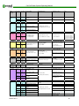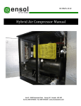
1
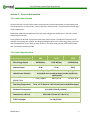
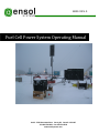
M1012 REV. 0
Fuel Cell Power System Operating Manual
Unit 2 - 5550 Panorama Drive Surrey, BC Canada V3S 1B7
Tel: 604-576-8333 Fax: 604-576-8233
www.ensolsystems.com
Fuel Cell Power System Operating Manual
Forward
Thank you for purchasing Ensol System’s Fuel Cell Power System.
Please read through this reference guide before operating the unit as it contains particular start
up, shut down and disconnection procedures.
If you have any questions or concerns, contact Ensol at:
Ensol Systems Inc.
Unit 2 – 5550 Panorama Drive
Surrey, BC, Canada, V3S 1B7
Tel: 604-576-8333
Fax: 604-576-8233
Email: [email protected]
www.ensolsystems.com
M1012 REV. 0
2
Fuel Cell Power System Operating Manual
Table of Contents
Contents
Section 1 – Quick Startup Procedure........................................................................................................ 4
Section 2 – General Information .............................................................................................................. 5
2.1 Product Introduction...................................................................................................................... 5
2.2 Product Specifications.................................................................................................................... 5
Section 3 System Installation ................................................................................................................... 6
3.1 Installation Overview ..................................................................................................................... 6
3.2 Batteries ........................................................................................................................................ 6
3.3 Methanol Fuel Cell ......................................................................................................................... 7
Section 4 System Operation..................................................................................................................... 7
4.1 General System Operation ............................................................................................................. 7
4.2 Fuel Cell Operation ........................................................................................................................ 8
4.3 UN Certified Methanol Fuel Cartridges......................................................................................... 10
4.4 Operational States ....................................................................................................................... 11
4.5 Default Parameters of cutoff threshold ........................................................................................ 12
4.6 Startup and Shutdown Phases...................................................................................................... 13
4.7 Anti–Freeze Protection Mode ...................................................................................................... 14
4.8 Operation at the Device ............................................................................................................... 15
4.9 Service Fluid................................................................................................................................. 16
4.10 Battery Connection .................................................................................................................... 17
Section 5 Error Messages....................................................................................................................... 18
5.1 Error Classifications Ranges.......................................................................................................... 18
5.2 Error Types .................................................................................................................................. 18
5.3 Most Common Error Messages .................................................................................................... 18
M1012 REV. 0
3
Fuel Cell Power System Operating Manual
Section 1 – Quick Startup Procedure
1.
2.
3.
4.
5.
6.
7.
8.
9.
10.
11.
Ensure all fuses and/or circuit breakers are open or set to ‘Off’
Connect the battery leads to the batteries if required.
Plug the remote into the RJ45 port labeled ‘Remote’ on the fuel cell.
Connect fuel line to methanol cartridge.
Insert the exhaust tube from the fuel cell, to the water collection tank port.
Ensure the 2” exhaust port from the water collection tank is connected.
Plug the power connector into the fuel cell.
Close all fuses and/or circuits breakers.
Turn the system on using the power button the remote, or the button on the fuel cell.
If the display of remote control shows “Automatic“ – device is ready
Functionality check: Switch on device manually – check if charging starts (this is only possible if
battery voltage < 13.2 V)
12. Ensure the thermostat is set at an appropriate temperature (less than 45oC).
13. Remove any tools from the enclosure, store service fluid and user manual.
14. Close the enclosure and ensure that it is properly sealed.
M1012 REV. 0
4
Fuel Cell Power System Operating Manual
Section 2 – General Information
2.1 Product Introduction
The Ensol Systems Fuel Cell Power System can be used to provide reliable power for measurement and
control equipment, air compressors, chemical injection, communications, surveillance and a broad range
of other applications.
Powered by a DMFC (Direct Methanol Fuel Cell), these packages are reliable even in the most remote
and harsh environments.
These systems can be used in conjunction with other power systems. Typically Ensol ties the fuel cell
packages into existing solar systems. The design philosophy then is to use solar energy when you have it,
with a methanol fuel cell as a back-up when you don’t. This will provide you with 100% reliable power
even in the darker months of winter.
2.2 Product Specifications
Max. Energy Output
Nominal Power
Hybrid Power Solutions
Nominal Current
@12 V / 24 V
EFOY Pro
600
EFOY Pro
1600
EFOY Pro
2200
600 Wh/day
1,560 Wh/day
2,160 Wh/day
25 W
65 W
90 W
Cascading multiple EFOY Pro units and integrating them
into hybrid solar or wind packages provide significantly
higher power
2.1 A / 1.05 A
5.4 A / 2.7 A
7.5 A / 3.75 A
Operating Temperature
-20 to +45 °C (Rated to -40C in Ensol Systems Hybrid Packages)
Methanol Consumption
0.9 L/kWh (0.24 US gal/kWh)
Dimensions (L x W x H)
433 x 188 x 278 mm (17 x 8 x 11 in)
EFOY Pro Weight
M1012 REV. 0
ca. 8 kg (18 lbs)
5
Fuel Cell Power System Operating Manual
Section 3 System Installation
3.1 Installation Overview
The Fuel Cell Power System’s electrical rating is General Purpose and shall therefore be installed outside
the Hazardous location. Typically the system will be mounted 3 meters away from any source of gas and
0.6 meters off the ground.
The Fuel Cell Power System also has an exhaust port located on the bottom of the unit. In order for the
unit to operate, this port shall not be blocked and needs at least a 300cm space left open below it.
3.2 Batteries
Sealed Lead-Acid batteries may be provided to store the fuel cell energy. Battery cables provide the link
between the batteries, equipment and charging system. Faulty connections can lead to poor
performance and terminal damage, meltdown or fire.
Batteries Inspection
• Examine the outside appearance of the battery. The tops of the batteries and terminal
connections should be clean, free of dirt and corrosion, and dry.
• If fluid is on the top of a gel or AGM battery this means that the battery is being overcharged
and the performance and life will be reduced
• Check battery cables and connections. Replace any damaged cables with a min. #12 AWG.
Tighten any loose connections.
Changing or Disconnecting Batteries
• Use extreme caution while working on the batteries and ensure appropriate PPE is utilized.
• First isolate the batteries from the electrical system by disconnecting all fuses and/or circuit
breakers.
• Disconnect the leads from the batteries, first beginning with the positive leads, then continue to
disconnect the remaining batteries from one another
• When reconnecting the batteries, please ensure that they are wired appropriately for 12 or
24VDC as your electrical system requires. Wiring the batteries incorrectly can result in an over
voltage condition and damage process equipment wired to the power package.
• Once the battery bank is connected, check that the voltage going to the system is within the
range (dependent upon a 12 or 24VDC electrical system). If the wiring is correct and the voltage
is still not within the correct range test each battery individually to see if any are defective or
damaged.
• If the voltage is within the range reconnect all the loads via the fuses and/or circuit breakers.
M1012 REV. 0
6
Fuel Cell Power System Operating Manual
3.3 Methanol Fuel Cell
The EFOY Pro Fuel Cell will already be mounted, but all its accessories still may need to be connected.
Connect all accessories in the following order:
•
•
•
First, connect the methanol fuel cartridge(s). Screw the M28 cartridge adapter to the
cartridge(s) if not already done so. Then connect the fuel line to the cartridge(s). If there is only
one cartridge in the system, screw the fuel line from the fuel cell to the top of the M28 adapter.
If there are two cartridges, screw the fuel line into the Duo Cart switch, then connect the two
fuel lines coming from the duo cart switch to each cartridge.
Second, connect the exhaust tubing line to the EFOY Pro fuel cell’s exhaust port. This is a small
tube stub protruding just next to the fuel line.
Third, connect the wiring harness and remote to their respective ports. Ensure that the remote
is plugged into the ‘Remote’ RJ45 port and not the ‘Data’ port.
Section 4 System Operation
4.1 General System Operation
The fuel cell power system is a simple package consisting of a methanol fuel cell to charge a bank of
sealed lead-acid batteries. This stored electrical power is then used to run measurement and control
equipment and whatever other loads may be involved. A typical hybrid application where the fuel cell is
connected in parallel with a solar system is illustrated in Figure 1.
Figure 1 – Hybrid System
M1012 REV. 0
7
Fuel Cell Power System Operating Manual
4.2 Fuel Cell Operation
The SFC EFOY Pro fuel cell uses a catalytic process to directly convert methanol into electricity (see
Figure 2). The byproduct of this reaction is water, small amounts of CO2 and heat. To eliminate freezing,
the water must be collected internally. The collected water should be changed out at the point in time
that the fuel cartridge is replaced.
Figure 2
Since the EFOY Pro fuel cell is a ‘smart’ fuel cell, charging and monitoring to the batteries is handled
automatically (example in Figure 3). With the remote which is included, the user can view the charging
mode, battery voltage, charging current, system operating hours and firmware version, and can also
change the charging mode. By pressing the power button on the remote, the user can turn the system
off, put it in automatic or turn the system on for one charge cycle.
M1012 REV. 0
8
Fuel Cell Power System Operating Manual
Figure 3
Ensol Systems has pre-programmed the fuel cell’s parameters for the installation location. If charging
voltage set points need to be altered, please contact Ensol Systems.
For a full description of the EFOY Pro fuel cell’s operation, please see the manual provided by SFC’s
document 101123_UM_EFOY_Pro_GB_v02.
M1012 REV. 0
9
Fuel Cell Power System Operating Manual
4.3 UN Certified Methanol Fuel Cartridges
The EFOY Pro uses special plastic fuel cartridges to facilitate ease of use and transport:
•
•
•
•
•
The methanol fuel cartridges are UN certified containers certified for transport on cargo planes.
The containers are spill resistant and designed to withstand significant impact force.
Ensol Systems will recycle empty plastic cartridges and dispose of any residual methanol if
necessary.
28L cartridges are the largest available size and a cartridge adapter is required to use this
cartridge with the EFOY Pro fuel cell. DO NOT THROW AWAY THE CARTRIDGE ADAPTER!
The fuel cell methanol is ultrapure. Do not puncture the cartridge. To avoid contamination, do
not transfer residual methanol from an old cartridge to a new cartridge. DO NOT USE ANY
OTHER METHANOL SOURCE TO FUEL THE EFOY PRO! Impure/contaminated methanol will
severely degrade the performance and life of the EFOY and will VOID WARRANTY.
M1012 REV. 0
10
Fuel Cell Power System Operating Manual
4.4 Operational States
•
Note that a minimal battery voltage of 9.0V or 18.5 V is required for the EFOY Pro to start.
M1012 REV. 0
11
Fuel Cell Power System Operating Manual
4.5 Default Parameters of cutoff threshold
New charging strategy (firmware 9.20 since mid of August 2010):
•
•
•
•
•
Switch on voltage: 12.3 V (11.0 - 13.0 V)
Switch off voltage: 14.2 V (13.5 - 14.7)
Switch off current: 2 A / 4 A @ EFOY Pro 2200 (0.5 - 10 A)
Switch off time: 3 hours (0 - 5 hours)
This ensures full battery charging and maximizes battery life
M1012 REV. 0
12
Fuel Cell Power System Operating Manual
4.6 Startup and Shutdown Phases
M1012 REV. 0
13
Fuel Cell Power System Operating Manual
4.7 Anti–Freeze Protection Mode
•
•
•
•
•
•
•
•
Note that the standard Ensol Systems Fuel Cell Power Packages are rated to -40C operation.
THE ANTI-FREEZE PROTECTION MODE WILL NOT WORK WITHOUT FUEL! Please ensure that the
fuel cell does not run out of methanol in freezing temperatures. If the fuel cell freezes, 24 hours
will be required for the fuel cell to warm back up and be returned to service.
The Anti-Freeze Mode will keep the EFOY Pro warm while the temperature is below 5oC (This
will work even when the unit is “OFF”).
Anti-Freeze Mode requires the connection to a faultless, adequately charged battery and fuel
cartridge.
Fuel consumption will be dependent upon external temperature differential. Weather,
insufficient insulation, ambient temperature and operating mode can have an impact on fuel
consumption.
The EFOY Pro does not give the produced energy to a fully charged battery in Anti-Freeze Mode.
Rather, the stack “burns” methanol and supplies the peripheries (pumps, etc…) to heat up the
system. The batteries will not be overcharged.
The EFOY Pro can operate in -20 oC temperature. Proper heat management and insulation is
required to ensure reliable operation at -40 oC.
Startup temperature (when the Anti-Freeze Mode has not been activated) is 5 oC.
M1012 REV. 0
14
Fuel Cell Power System Operating Manual
4.8 Operation at the Device
Remote Control:
M1012 REV. 0
15
Fuel Cell Power System Operating Manual
4.9 Service Fluid
•
•
•
•
If service fluid is low the yellow light will turn on at the EFOY Pro and the message “Please refill
service fluid” will appear at the control panel display.
Normally, there is no need to add service fluid prior to the initial start-up.
Note that the fuel cell produces its own service fluid during operation. This is critical to the
function of the device. If the EFOY Pro is operated continuously at temperatures above the
acceptable operating range (45 oC), the service fluid will be expelled faster than it can be
regenerated and cause a failure. For this reason, it is critical that the thermostat and fan
provided with the Fuel Cell Power Package are maintained in working order and set at an
appropriate temperature.
Service fluid can be added by removing the exhaust line as pictured below.
M1012 REV. 0
16
Fuel Cell Power System Operating Manual
4.10 Battery Connection
M1012 REV. 0
17
Fuel Cell Power System Operating Manual
Section 5 Error Messages
5.1 Error Classifications Ranges
•
•
•
•
•
•
•
10
20
30
40
50
70
80
Internal hardware or firmware issue - Contact Ensol Systems.
Fuel - Change the cartridge and reset.
Service Fluid - Add service fluid and reset. Check thermostat and fan function.
Environmental Issue – Temperature too high or too low to maintain function.
Battery - Battery voltage too high or low. Check connections. Check solar charge controller.
Reservoir - Internal fuel problem. Check fuel connections and reset.
System - Internal voltage or system error. Reset.
5.2 Error Types
•
•
•
•
•
•
A = Automatic reset (after error cause is remedied)
M = Manual user intervention required
F = Anti-freeze protection is possible from this error, if the error cause currently no longer exists
P = Permanent error (not resettable)
R = Reset required to restart system
W = Warning
5.3 Most Common Error Messages
•
•
•
•
12, 13, 14 - Failure due to blocking of exhaust or circulation pump defect.
32, 31, 30, 41 - Failure due to high surrounding temperature. Check installation and ensure air
circulation is adequate.
52-54 - Check battery (voltage too low) and/or battery connection problem
72, 76 - Failure in Methanol dosing or internal sensors. Possible issues in Methanol cartridge
because of fuel line.
M1012 REV. 0
18
Fuel Cell Power System Operating Manual
Display
mes sage
Error code
error type
1
P
Please contact
service
Please contact
service
Please check
exhaust hose
Rem edial measur e
Potential error caus es
System configuration
incomplete
Repair by SFC required
Firmw are update failed
Se rious s ys te m error
Repair by SFC required
Stack damaged
10
P
15
P
13
A (1x / 30s )
R
F
Stack pow er output too low
14
A (1x / 30s )
R
F
Fluid le ve l se ns or de fect
17
R
F
11
A (1x /30s)
R
F
18
Please change
fuel cartridge
Error des cription
20
Empty fuel cartridge dete cted
(internal fuel sensor)
22
M
R
F
30
M
R
F
31
M
R
F
Interruption:
Surroundings too
w arm
32
A
F
Se rvice fluid le vel be low 40%
41
A
F
Te mparature to high (internal
se ns or)
Interruption:
Please defrost
device slow ly
40
A
M
Te mpe rature too low
(stack temperature sensor < 3 °C)
Please check
battery voltage
50
A
F
T
Batte ry voltage too low
(se nse line )
51
A
Batte ry voltage too high
(se nse line )
Please refill
service fluid
Please contact
service
Press RESET (max. 3 attempts),
re pair required if error re occurs
Low s ervice fluid level
(error 30: <20%, error 31: <5%)
Solve potential error caus e,
then press RESET (max. 3 attempts)
Exhaust hose blocked,
not sufficient fres h air
Change fuel cartridge
(solve error cause)
then press RESET
Error caus es if fuel cartridge not
e mpty:
- Bad connection of fuel cartridge
connector (air leak)
- Dirty fuel cartridge connector
Add service fluid
(solve potential error causes)
then press RESET
Test: disconnect exhaust
hose and press "Reset", if
fuel cell is now running the
exhaust hose is blocked
- Operation at high ambient
temperatures or insufficient cooling
air
- Fluid level measurement defect
Wait
(until temperature has dropped)
-Ambient temperature to high (avoid
direct sunlight)
- Poor air ventilation in installation
space
Defrost unit
(ca. 24 h at room temperature)
- Anti-freeze protection did not w ork
(due to an error)
Batte ry voltage < 10,5 / 21 V ->
charge w ith battery charger
Solve e rror cause
(check battery and connections)
Batte ry voltage > 16,5 / 33 V ->
check external battery charger and
disconnect if necessary
Che ck connection to battery:
- Check battery cables
- Check battery fuses
52
A
Battter y voltage too low
(pow er line )
53
A
Batte ry voltage too high
(pow er line )
54
A
Batte ry voltage meas ure me nt
de fect
70
R
Error fuel re se rvoir se ns ors
73
R
75
R
80
R
83
R
Internal fue l s ensor defect
Re se rvoir error (e mptying time
too long)
Press RESET (max. 3 attempts),
Internal voltage re fe rence out of
re pair required if error re occurs
tolerance
DC/DC-Transfor mer de fect
84
R
A
P
76
M1012 REV. 0
Hardw are de fe ct
Abnormal pow er difference
be tw ee n stack and output
Stack voltage too low
(error 11: during operation,
A (3x / 300s) error 18: during start-up)
R
F
M
R
F
Note s
If the error pers is ts a repair is
re quire d
Circuit Board defe ct
Se lf tes t equipm ent
Se rious re se rvoir error
Perm ane nt error - repair re quire d
- Error 70 or error 72
re occurre d 3 time s
19
Fuel Cell Power System Operating Manual
Please check fuel
cartridge
connector
72
A
M
F
R
Re se rvoir error (re filling time
too long)
Solve potential error caus e,
then press RESET (max. 3 attempts)
Please install
Filter XT
Please contact
service
38
W
Filte r EFOY XT is rem ove d
ins tall Filte r
only EFOY 2200 XT
85
R
Filte r-Circuit-Board EFOY XT not
de tecte d
Pres s RESET (max. 3 attem pts),
re pair required if error re occurs
only EFOY 2200 XT
137
A
Filte r change confirme d
no action re quire d
only EFOY 2200 XT
139
M
Filte r change is displayed
change Filter EFOY XT
only EFOY 2200 XT
no display
information
90
A
Antifre eze mode s uccess fully
no action re quire d
Update: DO NOT
UNPLUG
BATTERY
99
A
Firmw are update is pe rforme d
not interrupt firmw are update
no display
information
140
A
Antifre eze mode not pos sible
fix othe r error
no display
information
172
A
no display
information
184
A
Firmw are corrupt
update required
w ithout
A
No connect or
Check battery
w ithout
no display
information
Please change
Filter XT
Error 72 w as once ignore d
- Firmw are problem (FW <9.11)
- Bad connection of fuel cartridge
connector (pumps air)
- Dirty fuel cartridge connector
Firmw are update
recommended (fixed w ith
FW 9.11 or higher)
another error is blocking the
antifre eze mode
no action re quire d
Se lf tes t equipm ent
succe ss fully
no action re quire d
trans fer de fective fir mw are
re pe ate firm w are -update
Re mote control has no
conne ction to fue l ce ll
Che ck connection, load battery if
necess ary
- Remote control is connected to
w rong port (Data Interface)
- Batter voltage < 8,5 V
- No communication (defect)
M1012 REV. 0
20