1
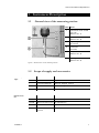
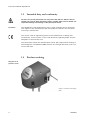
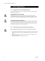
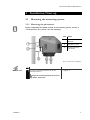
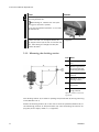
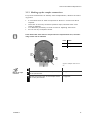
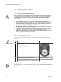
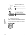
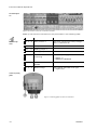
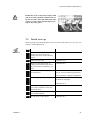
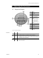
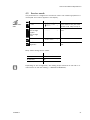
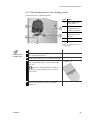
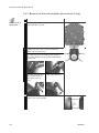
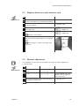
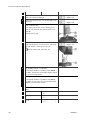
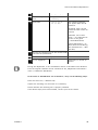
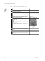
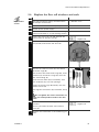
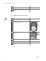
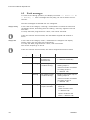
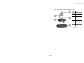
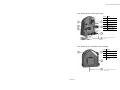
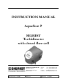
INSTRUCTION MANUAL AquaScat P SIGRIST Turbidimeter with closed flow cell Document No.: 10236E SIGRIST-PHOTOMETER AG Hofurlistrasse 1 CH-6373 Ennetbürgen Switzerland Phone: Fax: E-mail: Internet: Version: 1 Valid from: 1.4.2006 +41 (0)41 624 54 54 +41 (0)41 624 54 55 [email protected] www.photometer.com © SIGRIST-PHOTOMETER AG, Technical details subject to change 04/06 Instruction Manual AquaScat P Contents 1 Instrument Description.........................................................................1 1.1 General view of the measuring station.............................................1 1.2 Scope of supply and accessories ....................................................1 1.3 Intended duty and conformity.........................................................2 1.4 Product marking ...........................................................................2 1.5 Technical data ..............................................................................4 2 Safety Regulations ..............................................................................6 2.1 Symbols used on the photometer....................................................6 2.2 Precautions for ensuring safe operation ...........................................6 3 Installation/Start-up .............................................................................7 3.1 Mounting the measuring system .....................................................7 3.1.1 Mounting the photometer ......................................................7 3.1.2 Mounting the docking station ................................................8 3.1.3 Making up the sample connections .........................................9 3.2 Electrical installation....................................................................10 3.2.1 General installation points ...................................................10 3.2.2 Installation procedure..........................................................10 3.2.3 Making up the user connections...........................................11 3.3 Initial start-up .............................................................................13 4 Operating the Instrument ...................................................................15 4.1 Keypad and display .....................................................................15 4.2 Normal operation ........................................................................16 4.3 Service mode .............................................................................17 4.4 Set the national language.............................................................18 4.5 Select the measuring range ..........................................................18 4.6 Set the relay functions ................................................................20 4.7 Set the limits..............................................................................21 4.8 Set the access code ....................................................................23 4.9 Further possibilities .....................................................................23 5 Servicing..........................................................................................24 5.1 Servicing schedule ......................................................................24 5.2 General Instructions ....................................................................24 5.2.1 Fasten photometer to the docking station .............................25 5.2.2 Remove the flow cell assembly (for section 5.3 only) .............26 5.3 Replace desiccant and enclosure seal ............................................27 5.4 Manual adjustment......................................................................27 5.5 Clean the closed flow cell ............................................................30 5.6 Replace the flow cell windows and seals .......................................31 5.7 Replace the fine-wire fuses ..........................................................32 6 Troubleshooting ................................................................................33 6.1 Narrowing down the malfunction ..................................................33 6.2 Fault messages...........................................................................34 6.3 Customer service information .......................................................36 7 Taking Out of Service/Storage ............................................................38 8 Packing/Transport .............................................................................39 9 Disposal ...........................................................................................40 10 Spare Parts.......................................................................................41 10236E/1 i Instruction Manual AquaScat P 11 Appendix ......................................................................................... 42 11.1 General view of the closed flow cell ......................................... 43 11.2 General view of the optics unit ................................................ 45 11.3 General view of the flow cell assembly ..................................... 45 11.4 Service log ............................................................................ 47 12 Index............................................................................................... 49 ii 10236E/1 Instruction Manual AquaScat P Foreword This Instruction Manual describes the basic functions for operating the AquaScat P. It is addressed to all persons who are responsible for operation of the instrument. Operate the instrument only after having familiarized yourself with the contents of this Instruction Manual. In particular, be sure to study the section on safety rules before starting operation. Further documentation Symbols used in this Manual Doc. No. Title Contents 10237E Brief Instructions Most important functions and complete menu structure 10220E Reference Handbook More sophisticated menu functions and worksteps for advanced users 10221E Service Manual Repair and modification instructions for service technicians 10239E Data Sheet Technical data and duty ranges Important information Action Supplementary information Extremely dangerous voltage Fold-out help Fold-out help on the current topic in the Appendix 10236E/1 iii Instruction Manual AquaScat P iv 10236E/1 Instruction Manual AquaScat P 1 Instrument Description 1.1 General view of the measuring station Item Name 1 Photometer with closed flow cell (Section 3.1.1) 2 Sample outlet (Section 3.1.3) 3 Regulating valve (by others) 4. Flowmeter (optional) 5 Sample inlet (Section 3.1.3) 6 Docking station (Section 3.1.2) Figure 1: General view of the measuring station 1.2 Standard scope of supply: Optional accessories: 10236E/1 Scope of supply and accessories Units Name Versions/Remarks 1 Photometer AquaScat P 1 Instruction Manual German, English, French 1 Brief Instructions German, English, French 1 Reference Handbook German, English Art. No. Name Versions/Remarks diverse Flowmeter with/ without limit monitor 116706 Manual checking unit for AquaScat P 116694 Field bus interface Profibus DP diverse External SIREL control unit 85..264 VAC or 24 VDC 1 Instruction Manual AquaScat P 1.3 Intended duty and conformity Incorrect use of the photometer for duty other than that for which it was intended can result in false measuring results, possibly with process-related consequential damage and damage to the photometer itself! Intended duty The AquaScat P was developed for use in water treatment and is optimized with regard to the measurement span and ambient conditions for the values occurring in waterworks. The current rules of engineering practice were observed in its design and manufacture, which conform to the usual directives regarding safety and the obligation to exercise due care. The photometer meets the valid European Union (EU) requirements relating to electromagnetic compatibility (EMC) and the low-voltage directives, and it carries the CE mark. 1.4 Product marking Rating plate on the photometer (arrow) Figure 2: Location of the rating plate 2 10236E/1 Instruction Manual AquaScat P The photometer’s rating plate carries the following information: Item Data 1 Manufacturer 2 Product name 3 Date of manufacture 4 Frequency range 5 Disposal information (→ Section 9) 6 Observe the Instruction Manual! 7 CE mark 8 Power input 9 Service voltage 10 Serial No. 11 Country of manufacture Figure 3: AquaScat P rating plate The photometer’s Serial No. is also given in the * SYSTEM * menu (→ Reference Handbook). 10236E/1 3 Instruction Manual AquaScat P 1.5 Turbidity measurement AquaScat P Technical data Measuring principle scattered light measurement Measurement span 0 .. 100 FNU Sample medium water Wavelength 880 nm, to DIN EN ISO 7027 Radiation class LED device of Class 1 to EN 60825-1: 2002 Measurement angle 90 ° Resolution 0.001 FNU Power supply 85 .. 264 V / 47 .. 63 Hz or 24 VDC Back-up fuse max. 16 A Power input 11 W Current outputs 2 x 0/4 .. 20 mA, electrically isolated against earth to max. 50 V Burden max. 600 Ω Relay contacts 2 relay contacts 250 V, 4 A Control unit integrated control unit Measuring ranges 8 ranges from 0 .. 0.1 to 0 .. 100 FNU, freely configurable Enclosure plastics (ABS) Dimensions see Section 11 for detailed dimension drawing Weight about 3.6 kg Protection degree IP65 Maximum service altitude 2,000 m above sea level Ambient tempera- 0 .. 50 °C ture Ambient humidity 0 .. 95 % rel. humidity Interface 4 Modbus, optionally Profibus DP 10236E/1 Instruction Manual AquaScat P Flow cell 10236E/1 Material POM/ PVC Medium pressure max. 600 kPa = 6 bar Medium temperature 0 .. 40° C Sample flow 0.2 .. 2 l/min Connections hose connections: ∅ 16 mm GF system: G3/4“ threads 5 Instruction Manual AquaScat P 2 Safety Regulations 2.1 Symbols used on the photometer The symbols used on the instrument draw attention to the following safety measures or precautions: DANGER (BLACK ON YELLOW) Warning about a general source of danger. This symbol marks areas or manipulations that call for the observation of special safety rules. In these cases consult the Instruction Manual, which specifies the applicable rules. VOLTAGE (BLACK ON YELLOW) Warning about a dangerous electric voltage. This symbol marks energized areas with voltages higher than 48 VAC or 65 VDC where an electric shock hazard exists. In these cases be sure to observe the safety precautions and procedures prescribed in the Instruction Manual. 2.2 Precautions for ensuring safe operation Before starting up the instrument, be sure to observe these instructions. 6 To maintain the effectiveness of the type of protection, refrain from making any mechanical or electrical modifications to the instrument or parts thereof. Be sure to perform the operating steps prescribed in this Manual in the precise order stated. Remove covers in the deenergized state only. 10236E/1 Instruction Manual AquaScat P 3 Installation/Start-up 3.1 Mounting the measuring system 3.1.1 Mounting the photometer Before establishing the optimal position of the measuring system, be sure to consult Sections 3.1.2 and 3.1.3 in the following! Item Name 1 Bracket on photometer 2 Bracket on wall 3 Photometer support brace Figure 4: Photometer installation Mount photometer 1. Action Remarks Screw on mounting bracket (2) at the planned location. → Figure 4 Align the mounting bracket (2) horizontally with a spirit level! 10236E/1 7 Instruction Manual AquaScat P 2. Action Remarks Position the photometer (bracket 1) on mounting bracket (2). → Figure 4 When doing so, observe the two positioning pins (arrows in photo). Screw the photometer (bracket 1) to mounting bracket (2). 3. Loosen the lock nut of support brace (3). → Figure 4 Set support brace (3) so that it contacts the wall, thus taking the weight off the photometer bracket. 3.1.2 Mounting the docking station Item Name 1 Mains plug location 2 Measuring position of the photometer (mounting bracket) 3 Docking station position 4. AquaScat P on the docking station X Distance to docking station Y Distance to measuring position Figure 5: Position of the docking station The docking station (3) is used for parking the photometer (4) during servicing work (Section 5.2.1). Fasten the docking station (3) to the wall as close as possible (distance X) to the measuring position of the photometer (4), thus eliminating the need to unplug the power supply cable (1) (→ Figure 5). 8 10236E/1 Instruction Manual AquaScat P 3.1.3 Making up the sample connections For precise measurement of turbidity with the AquaScat P, observe the following points: A continuous flow of water as specified in Section 1.5 Technical data is required. Take care to avoid any excessive pressure drops, because these could cause air bubbles. It is absolutely necessary to install a valve for adjusting water flow. Do not use any transparent hoses. If the water flow rises above or drops below the required flow rate, the measuring results can be falsified! Item Name 1 Sample inlet 2 Sample outlet Figure 6: Sample inlet and outlet Action Make up the sample connections 10236E/1 Remarks 1. Attach the inlet hose to the sample inlet (1) of the photometer. → Figure 6 2. Attach the outlet hose to the sample outlet (2) of the photometer. → Figure 6 9 Instruction Manual AquaScat P 3.2 Electrical installation 3.2.1 General installation points The connection of live conductors can result in fatal injuries, and parts of the installation can also suffer damage. Only qualified personnel should perform the installation work. Be sure to observe the local codes when installation work is done. It is absolutely necessary to connect the protective earth conductor! Because the instrument possesses no mains switch, provide a suitable disconnection device (switch, plug) close to the mains connection. This device must be easily accessible and well marked! Do not apply voltage to the instrument until the installation work has been completed and the front cover is in place. The power supply must include a back-up fuse with a maximum tripping current of 16A. The cables must be able to withstand this load. Whenever malfunctions cannot be rectified, switch the instrument off and secure it against inadvertent restarting! 3.2.2 Installation procedure To access the connection terminals, remove the front cover. Proceed as follows: Action Remove front cover 1. Remarks Loosen the five screws (circled) on the front cover. Take off the front cover. 2. Make up the electrical connections. 3. When installation has been completed, reassemble the photometer in the reverse order. → Section 3.2.3 For information on use of the control signals, refer to the Reference Handbook, Section 2. 10 10236E/1 Instruction Manual AquaScat P The large terminals are dimensioned for mains voltage and can accommodate wires up to 2.5 mm2 cross-section (without ferrule). Terminal principle To open the terminals, use a size 1 screwdriver! 1. Force screwdriver (1) into opening. 2. Insert wire (2) into terminal. 3. Withdraw screwdriver (1) from opening. Figure 7: Large terminals The small terminals are dimensioned for low voltage and can accommodate wires up to 1.5 mm2 cross-section (without ferrule). 1. Press screwdriver against the actuator (1). 2. Insert wire (2) into terminal. Figure 8: Small terminals 3. Withdraw screwdriver. 3.2.3 Making up the user connections Remember: The photometer has no mains switch and becomes energized as soon as the connections are made! Be sure to select cables long enough to enable the instrument to be placed on the docking station (Section 3.1.2). Location of user terminals Figure 9: Location of the user terminals 10236E/1 11 Instruction Manual AquaScat P Terminal designations Figure 10: Location of the user connection terminals Make up the electrical connections to the photometer in the following order: Terminals Duty Terminal assignments Remarks 1. 4 - 5 - 6 Relay contact 1 2. 7 - 8 - 9 Relay contact 2 3. 10 .. 11 Reading output 1 4. 12 .. 13 Reading output 2 5. 14 - 15 Connection for flow monitoring The relay contacts are freely configurable (→ Section 4.6). Use small packing gland (A). → Figure 11 → Reference Handbook 6. 16 .. 18 Connection for Modbus → Reference Handbook RS 485 7. 1 - 2 - 3 Mains voltage Use packing gland (B) at far right (→ Figure 11). Location of packing glands Figure 11: Packing glands on back of instrument 12 10236E/1 Instruction Manual AquaScat P Bundle the cores of the power supply cable and of the relay terminals together with cable ties in such a way that inadvertent loosening of a core cannot possibly apply voltage to any other parts! 3.3 Initial start-up Work through the following table to carry out the initial start-up. If you run into trouble, consult Section 6. Action Initial start-up Remarks 1. Check the sampletaking system to → Section 3.1.3 make sure it is properly connected, then turn on the sample supply. 2. Check the flow rate. → Section 1.5 3. Make sure the photometer is properly mounted and the electrical connections are made up correctly. → Section 3.2 4. Switch on the power supply to the instrument. The instrument switches automatically to normal measuring operation. The momentary reading is displayed. 5. Set the language of your region. Now the menu texts are shown in the desired language. → Section 4.4 10236E/1 6. Set the measuring range for the two current outputs to suit your measuring duty. → Section 4.5 7. Set the relay functions to suit your measuring duty. → Section 4.6 8. Set the limits of the relays. → Section 4.7 13 Instruction Manual AquaScat P Action 9. 10. 14 Remarks Protect your settings against tam- → Section 4.8 pering with an access code. If you don’t need an access code, skip this step. Now the instrument is ready to start measuring. 10236E/1 Instruction Manual AquaScat P 4 Operating the Instrument 4.1 Keypad and display Item Name 1 Reading 2 Unit 3 Measuring range of reading output 1 4 Display for spike filter (dot appears whenever the spike filter detects an invalid reading) → Reference Handbook 5 Right key 6 Left key 7 Enter key 8 Down key 9 Up key Figure 12: Keypad and display. Key functions 10236E/1 Item Symbol Function 8/ 9 o/n 5/ 6 q/p 5+6 q+p Change from one menu line to another Change numbers in the editing mode (see below) Change from one function to another on a menu line Change function values or shift a number’s decimal point in the editing mode (see below) Press both keys together to return to normal operation 7 2 Activate editing mode (display shows > <) Enter the setting 15 Instruction Manual AquaScat P 4.2 Normal operation Upon being switched on, the instrument is in normal operation. The current reading/measuring range is shown continuously. The following displays may also occur (examples): The display... means... then you should... Reading (flashing) ... that following a restart or a switch from service mode to normal operation no valid readings are available yet, so the last readings are still being shown. - ...wait until the display stops flashing ...that the reading lies outside the valid measurement span (overrange). - ...make sure the maximum admissible value is not exceeded **** Fault **** ... ...that a serious malfunction has occurred. (measurement is interrupted) - ...troubleshoot the fault (→ Section 6). ** ...that a malfunction has occurred. (measurement continues) - ...troubleshoot the warning (→ Section 6). ***** FNU Warning ... 1 ** - ...just ignore the display if your process is going through an irregular phase. Table 1: Typical displays and what they mean. Press one of the keys q or p to consult the lower and upper limits of the currently set measuring range. q or p The range of reading output 1 is shown on the first line (example at left: measuring range 8). The range of reading output 2 is shown on the second line (example at left: measuring range 2). 16 10236E/1 Instruction Manual AquaScat P 4.3 Service mode The photometer is configured in the service mode. The measuring operation is interrupted and a menu appears in the display. Activate service mode Action Display (example) 1. 1xn Access code > ▓00000 < If you haven’t set your own access code, skip to step 3. 2. Enter code: o/n change number q/p change place Access code > ...... < Enter your own access code here. 3. 2 * ADJUSTMENT * SOLID REF. * * Instrument in service mode. 4. q+p (together) 5 Instrument in normal operation. 0.120 FNU Remarks Relay states during service mode: AL (alarm) deactivated (no alarm) LI (limit) deactivated SE (service) set AD (check) deactivated Depending on the configuration, the reading output switches to 0/4 mA or remains frozen at the last reading (→ Reference Handbook). 10236E/1 17 Instruction Manual AquaScat P 4.4 Set the national language Set the language of the menus and messages to your regional language as follows: Language Action Display (example) 1. Activate service mode * Access code > ▓00000 * < If you haven’t set your own access code, skip to Step 3 2. Enter code: o/n change number q/p change place * Access code > ...... * < Enter your own access code here 3. Service mode ac- * ADJUSTMENT * SOLID REF. tivated 4. 3xn * CONFIGURATION * 5. 1xp > Language English 6. Activate editing mode with 2 Language > English < 7. Select language: q/p Language > ... < 8. 2 > Language ... 9. q+p (together) 4.5 0.120 FNU Remarks * * < < 5 Confirm selection. Instrument in normal operation. Select the measuring range This is where you can select the desired range (→ Reference Handbook). Measuring range Action Display (example) 1. Activate service mode * ADJUSTMENT * SOLID REF. * * 2. 1xn * MEAS. RANGE * LIMITS * * 3. 1x q > Meas. range 2 < Activate editing mode with 2 3 Meas. range 2 > X < 4. 18 Remarks → Section 4.3 Measuring range of reading output 2. Here you can select one of the eight ranges (→ Table 2). 10236E/1 Instruction Manual AquaScat P Action 5. 6. 7. 8. Display (example) Meas. range 2 Select range with > 1 < q/p > Meas. range 2< 2 1 > Meas. range 1< 1x q Activate editing mode with 2 3 Meas. range 1 > X < Meas. range 1 Select range with > 8 < q/p > Meas. range 1< 10. 2 8 0.120 FNU 5 11. q+p (together) 9. Ranges set at the factory Remarks (e.g. measuring range 1) Confirm selection. Measuring range of reading output 1. Here you can select one of the eight ranges (→ Table 2). (e.g. measuring range 8) Confirm selection. Instrument in normal operation. During the standard calibration procedure, the following measuring ranges are set at the factory: Range Measurement span (FNU) Standard P User-specific 1 0 .. 100 2 0 .. 50 3 0 .. 30 4 0 .. 10 5 0 .. 3 6 0 .. 1 7 0 .. 0.3 8 0 .. 0.1 Table 2: Measuring ranges 10236E/1 19 Instruction Manual AquaScat P 4.6 Set the relay functions The photometer possesses two relay outputs (→ Section 3.2), whose functions are freely configurable. Several functions can be assigned to a given relay. The relay in question is activated whenever one of the configured functions becomes active (OR link). Relay functions Action Display (example) Remarks 1. Activate service mode * ADJUSTMENT * SOLID REF. 2. 3xn * CONFIGURATION* 3. 6xp > Relay 1 < li al se ad in Configure relay 1 4. 2 Relay 1 >li al se ad in< Activate editing mode. 5. Assign functions: o/n function on/off q/p change function Relay 1 >LI al se ab in< li= limit 1 exceeded al = alarm and warning (malfunction occurred) se = instrument in service mode ad = adjustment running in = relay inverted * * → Section 4.3 Functions written in CAPITAL LETTERS are activated (e.g. LI). 20 6. 2 > Relay 1 < LI al se ad in Confirm selection. 7. 1xp > Relay 2 < li AL se ad in Configure relay 2 8. 2 Relay 2 >li AL se ad in< Activate editing mode. 10236E/1 Instruction Manual AquaScat P 9. Action Display (example) Remarks Assign functions: o/n function on/off q/p change function Relay 2 >LI AL se ad in< li= limit 2 exceeded AL = alarm and warning (malfunction occurred) se = instrument in service mode ad = adjustment running in = relay inverted Functions written in CAPITAL LETTERS are activated (e.g. AL). 10. 2 > Relay 2 < LI AL se ad in 11. q+p (together) 0.120 FNU 5 Confirm selection. Instrument in normal operation. If you have configured one or two relays as limits, you also have to set the threshold values (→ Section 4.7). 4.7 Set the limits To render the limits usable, the relay outputs must be configured accordingly (→ Section 4.6). For each measuring range, up to two limits with upper and lower threshold values can be programmed. Whenever the reading reaches the upper threshold value, the limit becomes active and remains active until the reading drops back below the lower threshold value. Figure 13: Upper and lower threshold values of a limit The limits are available only if the relays are programmed accordingly (→ Section 4.6). 10236E/1 21 Instruction Manual AquaScat P Limits Action Display (example) 1. Activate service mode * ADJUSTMENT * SOLID REF. * * 2. 1xn * MEAS. RANGE * LIMITS * * 3. 1xp > Upper limit1 10.00 FNU < 4. 2 Upper limit1 > 10.00 FNU < 5. o/n change number q/p change place Upper limit1 > 11.00 FNU < 6. 2 > Upper limit1 11.00 FNU < 7. 1x p > Lower limit1 9.00 FNU < 8. 2 Lower limit1 > 9.00 FNU < 9. o/n change number q/p change place Lower limit1 > 8.50 FNU < → Section 4.3 Activate editing mode. Activate editing mode. Set upper threshold value. Confirm entry. Activate editing mode. Set lower threshold value. 10. 2 > Lower limit1 8.50 FNU < Confirm entry. 11. 1x p > Upper limit2 12.00 FNU < Follow same procedure for 2nd limit → steps 4 to 10. 12. q+p (together) 22 Remarks 0.120 FNU 5 Instrument in normal operation. 10236E/1 Instruction Manual AquaScat P 4.8 Set the access code You can use a self-defined access code to protect the photometer settings against tampering. Access code Action Display (example) 1. Activate service mode * ADJUSTMENT * SOLID REF. 2. 3xn * CONFIGURATION * 3. 3xq > Access code 000000 4. 2 Access code > 000000 < 5. o/n change number q/p change place Access code > ...... < Enter the new code in the spaces below so it won’t be forgotten! 6. 2 > Access code ... < Confirm selection. 7. q+p (together) 0.120 FNU Remarks * * → Section 4.3 < 5 Activate editing mode. Instrument in normal operation. New access code: If you ever forget the access code, only a SIGRIST service technician can delete it! 4.9 Further possibilities This documentation only describes the options that are necessary for the initial start-up and normal operation of the instrument. Other parameters enable you to adapt the AquaScat optimally to your specific measuring duty. For example, you can alter the behavior of the reading outputs or test the instrument in the manual mode. For information on these other possibilities, consult the Reference Handbook supplied with your instrument. 10236E/1 23 Instruction Manual AquaScat P 5 Servicing 5.1 Servicing schedule Recommended servicing work: When Who What Where as needed User Replace desiccant and enclosure seal (→ Section 5.3) four times a year or as needed User Manual adjustment (→ Section 5.4) as needed User Clean the closed flow cell (→ Section 5.5) as needed User Replace the flow cell’s windows and seals (→ Section 5.6) Table 3: Servicing schedule. 5.2 General Instructions Observe the safety instructions before starting servicing work. Perform the worksteps precisely in the order stated. When replacing parts, use only the genuine spares specified in the spare parts list (→ Section 10). For returns to the factory, observed the directions in the Instruction Manual regarding packing and transport. Never use aggressive cleaning agents or solvents to remove lime residues from the instrument. 24 10236E/1 Instruction Manual AquaScat P 5.2.1 Fasten photometer to the docking station (for Sections 5.3, 5.5 and 5.6 only) Item Name 1 Mains cable with mains outlet 2 Mounting bracket for photometer in measuring position 3 Knurled screw for fastening the photometer 4 Docking station 5 Photometer Figure 14: Photometer on the docking station Action Fasten photometer to docking station 1. Shut off the sample supply and disconnect the sample connections. 2. Wait until the flow cell is completely drained. 3. Remove the photometer (5) from the measuring position and place it on the docking station (3). → Figure 14 Make sure the photometer’s fastener is aligned with the docking station’s recess (grey area). 4. 10236E/1 Fasten photometer (5) with the knurled screw (3). 25 Instruction Manual AquaScat P 5.2.2 Remove the flow cell assembly (for section 5.3 only) Action Fasten optics unit to docking station 1. Loosen the five fastening screws of the flow cell assembly (circled). 2. Loosen the four clips on the photometer. Open the clips this way: 1. Press red catch in the direction of the arrow (this requires force) and simultaneously lift the clip. 2. Press the clip over 3. Flip open the clip. the closure plate of the optics unit (arrow). 3. 26 Now take out the flow cell assembly and place it on a firm surface. 10236E/1 Instruction Manual AquaScat P 5.3 Replace desiccant and enclosure seal Action Replace desiccant 1. Remove the photometer from the measuring position and fasten it on the docking station. → Section 5.2.1 2. Take out the flow cell assembly and place it on a firm surface. → Section 5.2.2 3. Remove the desiccant (1) and replace it with new desiccant. → Figure 17 4. Check the enclosure seal (7). → Figure 16 Replace it if necessary. 5. Put the flow cell assembly back on the optics unit and close the photometer in the reverse order. When doing so, observe the guide pins (arrows)! 5.4 Manual adjustment It is advisable to clean the flow cell before starting the manual adjustment (→ Section 5.5). Manual adjustment 10236E/1 Action Display (example) 1. Activate the service mode * ADJUSTMENT * SOLID REF. * * → Section 4.3 2. 1xp > Check value 23.75 FNU < Check whether the value agrees with the figure on the control unit. 3. Turn off the sample supply and disconnect the sample connections. 4. Wait until the flow cell is completely drained. → Section 3.1.3 27 Instruction Manual AquaScat P Action 5. 6. Display (example) Loosen the screw cap (3) and remove the flow cell’s bottom plate (4). → Figure 15 Insert the checking unit (1) as directed in the following. → Figure 15 Press in button (A). Now align groove (D) of the checking unit with pin (C) and slip the checking unit onto post (B). Release button (A). 7. Reinsert the flow cell’s bottom plate (4) (now with checking unit 1) into the flow cell housing and fasten it with screw cap (3). → Figure 15 Pin (E) must mate with hole (F)! 8. For turbidity levels < 0.5 FNU If the water exhibits a turbidity level below 0.5 FNU, reconnect the sample supply and fill the flow cell with water. For turbidity levels > 0.5 FNU If the water exhibits a turbidity level above 0.5 FNU, fill the flow cell with filtered water instead of the process water. Now the instrument is ready for the adjustment. 9. 28 1xp > Adjust no < 10. 2 Adjust > no < 11. 1 x p Adjust > yes < 10236E/1 Instruction Manual AquaScat P Action Display (example) 12. 2 Confirm adjustment Adjustment running … 13. Read value Check value 28.35 FNU The following displays can appear after the adjustment: Checking value: the adjustment could not be carried out “Recalibr. out of tolerance” = the required correction is too great (→ described below) „Fault Adjustment“= A fault has occurred during the measurement (→ Section 6.2) 14. Remove the checking unit in the reverse order and close the photometer. 15. Reconnect the sample supply. 16. q+p (together) 0.120 FNU 5 Instrument in normal operation. During the adjustment, a new recalibration factor is calculated. The deviation from the original condition can be consulted in the „Adjustment Information“ menu (→ Reference Handbook). In the event of “Recalibration out of tolerance“, carry out the following steps: Clean the flow cell (→ Section 5.5). Inspect the checking unit and clean it if necessary. Check whether the checking unit is properly installed. If the above steps prove unsuccessful, contact your service office. 10236E/1 29 Instruction Manual AquaScat P 5.5 Clean the closed flow cell Action Clean flow cell windows 1. Shut off the sample supply and disconnect the sample connections. 2. Wait until the flow cell is completely drained. 3. Remove the photometer from the measuring position and fasten it on the docking station. 4. Loosen the screw cap (3) and take off the flow cell’s bottom plate (4). 5. → Section 3.1.3 → Section 5.2.1 → Figure 15 Clean the interior of the flow cell (arrow) with a cotton rag. Clean the flow cell windows with cottontipped swabs! Admissible cleaning agents → Section 5.2 30 6. Refasten the instrument in the measuring position. 7. Carry out a manual adjustment. 8. Reassemble the instrument in the reverse order. 9. Reconnect the sample supply. → Section 5.4 → Section 3.1.3 10236E/1 Instruction Manual AquaScat P 5.6 Replace the flow cell windows and seals Action Replace windows and seals 1. Shut off the sample supply and disconnect the sample connections. 2. Wait until the flow cell is completely drained. 3. Switch off the power supply. 4. Remove the instrument from the measuring position and fasten it on the docking station. 5. Loosen the screw cap (3) and take off the bottom plate of the flow cell (4). 6. Loosen the four screws fastening the flow cell (circled) and remove the flow cell. 7. Remove the twelve screws (A) that fasten the thrust rings (B). → Section 3.1.3 → Section 5.2.1 → Figure 15 Now remove the three thrust rings (B), three windows (C) and three o-rings (D) from the flow cell housing (E). Place the new seals (D) (if necessary with new windows (C)) into the openings. Fasten the thrust rings (B) loosely with the twelve screws (A). Now tighten the screws (A) clockwise, bit by bit. Do not tighten the screws crosswise, because this could produce cracks in the windows! 8. Reinstall the flow cell housing (E) in the instrument. → Figure 15 (Do not yet install the flow cell’s bottom plate (3)) 9. 10236E/1 Refasten the instrument in the measuring position. 31 Instruction Manual AquaScat P Action 10. Carry out a manual adjustment. → Section 5.4 11. Restart the photometer in normal measuring operation. 5.7 Replace the fine-wire fuses Action Replace fine-wire fuses 32 1. Switch off the power supply to the photometer. 2. Loosen the five screws (circled) on the front cover and remove them. 3. Remove the old fine-wire fuses (A) from the motherboard. 4. Insert the new fine-wire fuses on the motherboard. 5. Fasten the front cover with the five screws. 6. Switch the power supply to the photometer back on. Remarks → Point 2 10236E/1 Instruction Manual AquaScat P 6 Troubleshooting 6.1 Narrowing down the malfunction To narrow down the malfunction, work through the following table step by step. If the listed action fails to produce the desired result, please consult Customer Service (→ Section 6.3). Perceived malfunction Action No display - Make sure the supply voltage is applied (→ Section 3.2). - Check the fine-wire fuses on the motherboard (→ Section 5.7). Display shows a fault message - Analyze the fault message (→ Section 6.2). The reading appears to be faulty - Make sure the medium in the product pipe is in accordance with the operating conditions (→ Section 1.5). - Check whether the photometer is properly mounted (→ Section 3.1.1) - Check whether the sample connections are properly made up (→ Section 3.1.1) - Check whether the right measuring range is set (→ Section 4.5) - Make sure the servicing work has been done in accordance with the servicing schedule (→ Section 5.1) - Check the flow rate. - Carry out an adjustment (→ Section 5.4) 10236E/1 33 Instruction Manual AquaScat P 6.2 Fault messages If a fault occurs during operation, the display will show **** Fault **** or ** Warning ** with a message that may help you narrow down the malfunction. The fault messages are divided into two categories. Category warning In the case of the category "warning", measurement continues as usual and the display shows, alternating with the reading, “warning“ together with the fault text. If a relay has been programmed to "fault", this will be activated. If the limit monitor was activated, this will not be stopped and remains in force! Category fault In the case of the category "fault", measurement is stopped. The display shows “fault” with the fault text continuously. If a relay has been programmed to "fault", this is activated. The current outputs go to 0 mA. If the limit monitor was activated, this will be stopped and must be reset! Message Category Measurement Fault Current 1 Warning Means Possible causes A fault has occurred during measurement. - defective electronics (→ Service technician) The reading output is malfunctioning. - break in the current loop of reading output 1 - maximum burden exceeded at reading output 1 (→ Section 1.5) Current 2 Warning The reading output is malfunctioning. - break in the current loop of reading output 2 - maximum burden exceeded at reading output 2 (→ Section 1.5) Moisture 34 Warning Moisture too high in optics chamber - replace desiccant (→ Section 5.3) - check enclosure seal (→ Section 5.3) - replace windows and seals (→ Section 5.6) 10236E/1 Instruction Manual AquaScat P Message Category Means Possible causes Flow rate Fault The minimum sample flow is not being reached. On instruments with a flowmeter with limit contact: - sample supply interrupted - simple inlet clogged Without a flowmeter with limit contact: - jumper between terminals 14 and 15 is open LED Fault The reference photocell is not receiving any light. - defective light source (→ Service technician) - defective photocell or electronics (→ Service technician) - flow cell badly fouled (→ Section 5.5) - sample medium exhibiting excessively high turbidity 10236E/1 35 Instruction Manual AquaScat P 6.3 Customer service information Whenever you have questions about SIGRIST products, please start by reading the documentation supplied with the equipment. Also check the Errata accompanying the documentation. These contain information that became available subsequently. If you do not find the answer, please contact the Service Office responsible for your country or your region. If you don’t know where to find it, Customer Service of SIGRIST-PHOTOMETER AG in Switzerland will gladly give you the relevant contact address. You will also find the current list of all SIGRIST country representatives in the Internet at www.photometer.com. Whenever you contact a SIGRIST Service Office or Customer Service, please make sure you have the following information at hand: 36 A description of the instrument behavior and the worksteps being performed as the problem arose. A description of how you proceeded when trying to solve the problem yourself. Documentation on any non-SIGRIST product operated together with the photometer or its peripheral devices. 10236E/1 Instruction Manual AquaScat P Instrument data If you have problems with the reading, please have the following additional information at hand; you can find it in the “info” section of the menu structure: Name Option Value Remarks Serial No. Fault messages F01 F02 F03 F04 F05 F06 F07 F08 F09 F10 System faults S01 S02 S03 S04 S05 10236E/1 Recalibration value Recalibr. 1 Calibration factor Moni/meas.1 Checking value Ref. Value 37 Instruction Manual AquaScat P 7 Taking Out of Service/Storage The goal of the taking-out-of-service procedure is to prepare the photometer properly for storage and to keep it in good condition during the storage period. Action Taking out of service 1. Switch off the power supply to the photometer and disconnect all electrical connections. 2. Turn off the sample supply and disconnect the inlet and outlet tubes from the photometer. 3. Thoroughly clean all surfaces that have come into contact with the medium. No toxic, corrosive or loose deposits may remain inside the instrument (→ Section 5.2). 4. Remove the photometer from the measuring station. 5. Make sure that all openings on the photometer are closed off. No special conditions are required for storage of the equipment, but be sure to observe the following: 38 The photometer contains electronic components. The storage conditions must satisfy the normal requirements for such components. In particular, the storage temperature should remain within the –20 … +50°C range. All components that come into contact with the medium during operation must be kept dry and clean for an extended period of time before being put into storage. During storage, the photometer and accessories must be protected against weathering, condensing moisture and aggressive gases. 10236E/1 Instruction Manual AquaScat P 8 Packing/Transport Whenever possible, use the original packing materials when packing the photometer and its peripherals for shipment. If the materials are no longer available, observe these instructions: 10236E/1 Prior to packing, close all openings of the photometer with pressuresensitive tape or plugs to prevent any packing materials from penetrating them. The photometer contains optical and electronic components. Pack the instrument in such a way that it is protected against impact and blows during shipment. Pack all of the peripheral devices and accessories separately, and mark each part with the serial number (→ Section 1.4). This will prevent mixups later on and facilitate identification of the parts. 39 Instruction Manual AquaScat P 9 Disposal This product is covered by the European Directive RL 2002/95/EG (RoHS) in Category 9 "Monitoring and Control Instruments". The photometer and its peripherals must be disposed of in accordance with the regional statutory regulations! The photometer does not contain any environmentally polluting sources of radiation. Its material should be disposed of or recycled in accordance with the following table: Category Materials Disposal possibilities Packing Cardboard, wood, paper Reuse as packing material, local waste disposal points, incinerators Protective films, polystyrene shells Reuse as packing material, recycle Elektronics Printed circuit boards, electromechanical components Disposal as electronics scrap Optics Glass, aluminium Recycle via used-glass and scrap metal collection points Flow cell POM/PVC Local collection point Enclosure Plastics ABS Local collection point Table 4: Materials and their disposal 40 10236E/1 Instruction Manual AquaScat P 10 Spare Parts The parts mentioned in this documentation and their article numbers are listed in the following table: Art. No. Article name 111391 Desiccant 116758 Enclosure seal 116517 Flow cell window 115681 Seal for flow cell window 115513 Fuse 1AT Table 5: Spare parts and article numbers 10236E/1 41 Instruction Manual AquaScat P 11 Appendix You can fold out the following pages so they lie next to the text. Following them are all of the required drawings and dimension sheets. 42 10236E/1 Instruction Manual AquaScat P 11.1 General view of the closed flow cell Item Name 1 Checking unit 2 Post for fastening the checking unit 3 Screw cap for fastening the bottom plate of the flow cell 4 Bottom plate of flow cell with inlet and outlet tubes 5 Outlet tube extension Figure 15: General view of the closed flow cell 10236E/1 43 Instruction Manual AquaScat P 44 10236E/1 Instruction Manual AquaScat P 11.2 General view of the optics unit Item Name 1 Beam diverter 2 Receiver 3 Mains connection 4 Docking station 5 Transmitter 6 Moisture sensor 7 Enclosure seal Figure 16: General view of optics unit 11.3 General view of the flow cell assembly Item Name 1 Desiccant 2 Flow cell 3 Support 4 Bottom plate of flow cell Figure 17: General view of flow cell assembly 10236E/1 45 Instruction Manual AquaScat P 46 10236E/1 Instruction Manual AquaScat P 11.4 Service log Service log Serial No.: Initial start-up: Remarks: Adj. value Recal1 before 10236E/1 after Servicing work carried out Date Initials 47 Instruction Manual AquaScat P 48 10236E/1 Instruction Manual AquaScat P 12 Index * ***** .................................... 16 A access code, setting ................ 23 accessories ............................... 1 adjustment, manual ................. 27 article numbers ....................... 41 B back-up fuse ........................... 10 Brief Instructions ....................... iii C cable length ............................ 11 cable ties................................ 13 CE ........................................... 2 clips, open .............................. 26 connection terminals ................ 10 cross-section .......................... 11 Current x............................. 34 Customer Service .................... 36 D danger ..................................... 6 Data Sheet ............................... iii disconnection device................ 10 display ..............................15, 16 disposal.................................. 40 docking station ................1, 8, 11 duty......................................... 2 E EMC ........................................ 2 environmental pollution ............ 40 Errata..................................... 36 EU ........................................... 2 F falsification of results................. 9 Fault .................................... 16 fault message ....................33, 34 fine-wire fuses, replacement ..... 32 flow cell ................................. 43 flow cell assembly ................... 45 flow monitoring ....................... 12 Flow rate............................. 35 flowmeter................................. 1 fuses, replacement .................. 32 G glands .................................... 12 H hoses ....................................... 9 10236E/1 I initial start-up ..........................13 installation.................................7 installation, electrical ................10 Internet ...................................36 K keypad....................................15 L language, setting......................18 LED ........................................35 limits, definition .......................21 limits, setting...........................22 M mains switch ...........................11 malfunctions............................10 malfunctions, narrowing down...33 marking.....................................2 Measurement..........................34 measuring ranges ............... 18, 19 measuring station.......................1 menus ....................................18 messages ................................18 Modbus ..................................12 motherboard ............................32 N no display ...............................33 normal operation ......................16 O optics unit ...............................45 P packing ...................................39 photometer................................1 power supply cable ..................13 precautions ...............................6 protection .................................6 protection, settings ..................23 protective earth .......................10 R rating plate ............................2, 3 reading outputs........................12 reading, faulty .........................33 reading, flashing.......................16 Reference Handbook.................. iii regional language .....................18 relay contacts ..........................12 relays, configuration .................20 relays, during service mode .......17 RL 2002/95/EG........................40 49 Instruction Manual AquaScat P RoHS...................................... 40 RS 485 ................................... 12 rules .........................................2 S safety .......................................6 sample connections ....................9 scope of supply .........................1 service log............................... 47 Service Manual ..........................iii service mode ........................... 17 Service Office.......................... 36 servicing schedule .................... 24 spare parts .............................. 41 spike filter ............................... 15 storage ................................... 38 symbols ................................iii, 6 50 T taking out of service ................ 38 technical data............................ 4 terminals................................. 11 U user connection terminals ......... 12 user terminals.......................... 11 V valve ........................................ 9 vertical .....................................iii voltage ..................................... 6 W warning .................................... 6 Warning................................. 16 water flow ................................ 9 www ..................................... 36 10236E/1