1
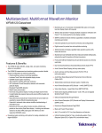
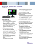
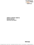
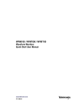
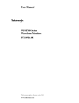
Multi-standard, Multi-format Waveform Monitors
WFM6120 • WFM7020 • WFM7120
Features & Benefits
Simultaneous A/B Input Support
Extends Monitoring Functions
(SIM Option)
Full Dual Link Support for Highend Production, Post Production
and Manufacturing Applications
(DL Option)
Numerical and Graphical Display
of A/V Delay (AVD Option)
FlexVu™ XGA Display Increases
Productivity with the Ability to
Create Hundreds of Custom
Multiple-view Displays Tailored
to Specific Work Practices
CaptureVu® Video Frame Capture
Improves Efficiency in Troubleshooting and Equipment Setup
(WFM6120 & WFM7120)
Exclusive Tektronix Gamut
Displays Help Ensure Compliant
Content
Tektronix’s Patented Timing
Display Simplifies Plant Timing
WFM6120
WFM7020
The SD-capable WFM6120 offers highperformance monitoring and measurement capabilities. It can be configured
to monitor either NTSC/PAL analog
video (Opt. CPS), SD Digital Video
(Standard), or both video formats.
Available audio options offer support for
monitoring digital audio (embedded and
AES/EBU inputs), analog audio and
Dolby audio formats. Available measurement options offer in-depth digital
data analysis and SDI signal measurements, such as Eye diagrams and jitter
as well as in-depth video data and
ancillary data analysis (Opt. DAT). AV
Delay Measurement capability (Opt.
AVD) can also be added to the
WFM6120.
The HD-capable WFM7020 offers
basic monitoring capabilities for applications involving HD digital video. It can
be configured to monitor NTSC/PAL
analog video (Opt. CPS), SD Digital
Video (Standard), HD digital video (Opt.
HD) or any combination of these video
formats. Available audio options offer
support for monitoring digital audio
(embedded or AES/EBU inputs) and
analog audio. Dual Link (Opt. DL) is
also available on the WFM7020.
WFM7120
The HD-capable WFM7120 offers highperformance monitoring and measurement for applications involving HD
digital video. It combines the video and
audio monitoring capabilities available
on the WFM7020 with available
support for Dolby audio (Opt. DDE), indepth data analysis (Opt. DAT), and SDI
signal measurement as well as AV
Delay Measurement (Opt. AVD). The
WFM7120 also supports Simultaneous
A/B Input Monitoring (Opt. SIM) as well
as DUAL Link Monitoring (Opt. DL).
99 Washington Street
Melrose, MA 02176
Fax 781-665-0780
TestEquipmentDepot.com
The Patented Tektronix Lightning
Display is Ideal for Maintaining
Correct Inter-channel Timing
Extensive Fault Monitoring,
Status Reporting, and Error
Logging Simplify Content
Quality Control
Available High-performance SDI
Physical Layer Measurements
(PHY Option) is Available for Eye
and Jitter Displays
In-Depth Digital Data Analysis
Helps Quickly Resolve Difficult
Quality and Reliability Issues.
(DAT Option)
Exceptional Audio Monitoring
Available, (Option AD) including
support for Dolby® Audio Formats
(Option DDE) and a Front-panel
Headphone Connector, Reduces
Time and Effort in Verifying Multichannel Audio Content
Front-panel USB Port For Easy
Storage and Transfer of Instrument
Settings and Video Data
System Upgrades can be done
over the Network or via USB
Applications
Monitoring and Compliance
Checking in Video Distribution
and Broadcasting
Quality Control in the Video
Production and Post-production
Equipment Qualification and
Troubleshooting in the Installation
and Maintenance of Video
Facilities and Systems
Multi-standard, Multi-format Waveform Monitors
WFM6120 • WFM7020 • WFM7120
Flexible Configurations and
Upgrades – Helping You Manage
the Digital Transition
To help address the challenges of
maintaining both legacy analog and
emerging digital video technology
during the digital transition, the
WFM6120 and the WFM7120\7020
offer an exceptionally broad range
of options and upgrades. Video
monitoring, audio monitoring and
measurement options can be added
to a previously purchased instrument
with field-installable upgrades. For
example, you can purchase a
WFM6120 configuration that only
monitors SD digital video and add
physical layer measurement capability
later. If you anticipate a future transition
to HD digital technology, you can
purchase WFM7020 or WFM7120
configurations without HD support
and then add this capability when
your needs change.
CaptureVu™ – Much More
than “Freezing” a Display
The CaptureVu capability on the
WFM7120 and WFM6120 can capture
and store the video data from an entire
video frame and display this data on
waveform, vector, gamut and picture
displays. Unlike “freeze” captures, you
can compare the live signal to capture
data in one kind of display (for example,
a waveform display), and then reconstitute the same data to make the same
live-to-capture comparison in a different
display (such as a vector or picture display).
2
CaptureVu can compare captured data and
live signal on multiple displays.
In addition to user-initiated captures,
the instrument can do a triggered
capture that automatically acquires
data on the occurrence of specific
faults. Triggered captures are particularly useful for finding intermittent errors
and in capturing data about fault conditions at remote sites. CaptureVu then
let’s you use a variety of displays and
settings to investigate the problem.
With CaptureVu, you can store a video
frame generated by one piece of equipment (for example, a camera) and use
this as a reference to configure other
equipment to have matching video
characteristics. The data can also be
stored on a USB memory device and
transferred to another instrument or
saved to a PC and provide further
detailed analysis using the CaptureVu
Utility available from the Tektronix Website.
Use FlexVu to create the multi-view display
that best fits your needs.
FlexVu™ Display Interface –
Four Instruments in One
The WFM6120 and the WFM7120/7020
models have an integrated, XGA-resolution
display with the Tektronix FlexVu user
interface. With FlexVu, you can combine
separate monitoring and measurement
displays four at a time, in almost any
combination. Unlike instruments with
pre-determined view combinations or
more restricted choices, FlexVu lets you
create a multi-view display best suited to
your specific needs and work practices.
Multi-standard, Multi-format Waveform Monitors • www.tektronix.com/video
Multi-standard, Multi-format Waveform Monitors
WFM6120 • WFM7020 • WFM7120
Waveform and Vector displays.
Quickly detect Gamut errors using specialized displays.
Waveform Displays – Quickly
Verify and Adjust Critical Signal
Parameters
Tektronix-exclusive Gamut
Displays – Efficiently Detect and
Correct Gamut Problems
Familiar video waveform displays can
show digital video signals in RGB,
YPbPr, YRGB, or composite formats
with flat or low-pass filtering. Waveform
displays of composite analog video
signals can show NTSC and PAL
signals with luma, chroma and
luma+chroma filtering. Signal components can be displayed in either parade
or overlay mode and in composite
format displays with setup selection.
The waveform display has several
sweep rates and easy control of vertical
gain and horizontal magnification to
help you efficiently monitor and
measure video waveform parameters.
With FlexVu you can see four differently
configured waveform displays of the
same signal. With the Simultaneous
Input Option different signal sources
can be compared side by side.
The patented Tektronix Diamond,
Split Diamond and Arrowhead gamut
displays simplify the process of verifying
gamut compliance. The Split Diamond
display helps easily identify and correct
RGB gamut errors in digital video
signals. The Arrowhead display saves
time in verifying the gamut compliance
of the composite video signal generated from a digital video signal. With
FlexVu, you can simultaneously monitor
both gamut displays to quickly gain
complete confidence in content compliance throughout the delivery chain.
Also, user-selectable gamut thresholds
let you tailor these displays, and the
associated gamut alarms, to your
particular compliance standards.
Vector, Lightning, and SCH Phase
Displays – Accurately Control
Color Parameters
The vector display offers user-selectable graticules, color targets (75% and
100%) and color axis. The patented
Tektronix Lightning display shows luma
and chroma amplitudes and lets you
verify component inter-channel timing
using a color bar signal. The SCH
Phase display helps quickly verify this
critical timing parameter of composite
analog video signals.
The pseudo composite signal while
simply derived from the Serial Digital
signal can help speed things up during
production processes such as camera
set up and has the added advantage of
being familiar to most people.
Timing Display – Simplify Plant Timing
The patented Tektronix Timing display
makes facility timing easy through a simple
graphical representation which shows the
relative timing of the input signal (the circle)
versus the reference signal (the crosshair).
SIM Module allows Digital-to-Digital and
Analog-to-Digital Timing.
Timing Display Showing A and B Link Timing
with DL Opt.
Picture display with Closed Caption, Safe
area graticules and gamut brightups.
For proper timing, the circle is centered
on the crosshair and changes color from
red to green. The display also has numeric
readouts of the timing difference relative
to the reference signal, showing vertical
timing as number of lines and horizontal
time difference in µsec. With the SIM
option Analog to Digital Timing of the input
signals or Digital to Digital Timing is
also possible.
Multi-standard, Multi-format Waveform Monitors • www.tektronix.com/video
Test Equipment Depot - 800.517.8431 - 99 Washington Street Melrose, MA 02176
FAX 781.665.0780 - TestEquipmentDepot.com
3
Multi-standard, Multi-format Waveform Monitors
WFM6120 • WFM7020 • WFM7120
For verifying and documenting
content compliance, the Video
Session display shows key status
information on the signal, plus quality
statistics like errored seconds and
percentage content with errors.
Picture Displays – Quick Visual
Conformation and Precision
Content Adjustment
A full-color picture display shows the
video content of the monitored input.
The instrument can display the picture
on the full-screen, or on up to four
views in a multiple-view display. For
different input formats, the picture
display automatically adjusts to
show the full image content.
The picture display can also show
content advisory codes and decoded
closed caption data (EIA608 formats)
for easy verification of this critical ancillary data.
Editors can choose from several Safe
Area graticules on the picture display
to quickly verify correct placement of
graphics, titles or logos. Graticule
choices include the Safe Action and
Safe Title graticules defined in the
SMPTE, ITU, and ARIB standards,
plus custom, user-definable graticules.
Using FlexVu, editors can see two or
more pictures with different graticules
to verify correct placement for different
formats and standards.
Alarms, status, quality logistics and logging.
Alarms, Quality Statistics and
Logging – Thorough and Fast
Content Verification
All models offer a variety of displays
for status at a glance signal
monitoring and quick, thorough
content verification.
Using the alarm status display, operators and technicians can quickly
detect video faults including gamut,
EDH, and CRC errors, SDI format
problems and many more. The
instrument offers several alarm notification methods, including on-screen
error icons, audible beep, groundclosure output and SNMP traps.
To support unattended monitoring,
and to supply documentation for
maintenance records or service level
agreements, the instrument logs
alarms and other key events (such as
format changes). Log entries can be
time-stamped with date, time-of-day,
and time code reference (VITC, ATC
or LTC). All models also offer extensive ancillary data monitoring. This
includes monitoring the presence of
closed caption content formats
defined by EIA608, EIA708, and
ARIB standards.
With the Simultaneous Input Option
Error Logging from the dual inputs is
combined in a single error alarm
display with the source of the error
indicated in the status bar.
You can also select brightup conditions that show the location of RGB
or composite gamut errors on the
picture display. Line and sample brightups show the location of the currently
selected line or video data sample. The
Blanking mode provides a quick check
as to whether ANC Data is present.
4
Multi-standard, Multi-format Waveform Monitors • www.tektronix.com/video
Multi-standard, Multi-format Waveform Monitors
WFM6120 • WFM7020 • WFM7120
Audio phase displays include phase
correlation meters, a flexible Lissajous
display (for any pair of channels) and a
multiple-channel Surround Sound*
display that shows audio levels (Aweighted or linear), total sound volume,
phantom source locations and the
dominant sound position.
Audio bars and Surround Sound* Displays.
Audio Monitoring – Versatile
Tools Help Confirm and
Adjust Sound Quality
The WFM6120 and the WFM7120/7020
offer several options for monitoring both
analog and digital audio.
Option Availability
Available on all Models – Option AD
monitors AES/EBU and analog audio
formats.
WFM7120 – Option DDE monitors Dolby
Digital (AC-3) plus support for monitoring
and decodes Dolby E as well as all the
audio formats included in Option AD.
Both audio options support the display
of Dolby presence.
Option DDE allows decode of the Dolby
audio formats and places a status
message in the appropriate audio bar,
eliminating confusion about audio input
formats. Dolby status displays offer indepth review of decoded Dolby metadata.
Both audio options have an audio bar
display that can display up to six audio
bars for analog inputs, up to eight audio
bars on AES/EBU inputs and embedded
audio sources. Up to ten audio bars are
displayed when decoding Dolby Digital
and Dolby E formats (DDE Option only).
The audio options provide user-selectable
scales, meter ballistics and audio level
indicators. In-bar messages show
status and fault conditions for each
monitored audio channel, reducing the
likelihood of an undetected audio problem.
The Audio Session display shows audio
error conditions (such as parity errors),
Loudness (Leq) as well as highest true
peak, and the number of detected,
clips, mutes, over-levels and silences.
User-specified threshold values determine over-level and silence conditions
and the duration a potential audio
problem must persist before the instrument generates an alarm.
In addition to monitoring audio inputs,
these options can generate analog or
digital audio outputs from the analog
or AES/EBU audio inputs. They can
also generate audio outputs from
embedded audio in the video input,
or by decoding Dolby audio inputs,
including stereo down-mixes. A
convenient front-panel headphone
connector lets you listen to any stereo
audio output.
The audio options can be used to deembed audio from the SDI signal and
output as digital or analog audio
depending on the option installed within
the instrument. Additionally, the audio
option can be configured to output
digital or analog audio from the selectable inputs or from the decoded Dolby
data stream.
With the available Dual Link (Opt. DL)
a total of eight Audio Channels can be
monitored from the total of up to 32
embedded audio channels. In the
Simultaneous (SIM) option two audio
tiles can be displayed with a flexible
configuration of 8-0, 6-2, 4-4, 2-6 and
0-8, a total of eight audio channels can
be displayed in this option.
Simultaneous Inputs.
Simultaneous A/B Inputs
Simultaneous input capability adds a
new level of power to working in the
multi-format environment. This option
allows two input signals to be monitored simultaneously allowing operation
staff to quickly determine if a video
quality problem existed in the input
signal, or arose within their facility.
Engineering staff can quickly detect,
isolate, diagnose and resolve technical
problems introduced by a piece of
video equipment or a video equipment
chain by quickly comparing the input
and output signals. This is especially
helpful when checking for transparency
during format conversion.
Flexible configuration of displays from two
monitored inputs, including waveform/picture
and waveform/audio
Simultaneous fault detection, status reporting,
alarm generation and error logging
The patented Tektronix Timing Display can be
used for facility timing allowing each source
to be measured, either to an external reference or to the other input signal
Audio and Video Sessions are independent
for each channel
The SIM option also allows Digital-to-Digital
or Analog-to-Digital Timing
By using the Saved Offset you can save the
timing from one signal and then show the
relative timing between the current signal
and the saved offset
CPS
SD
SD
HD
SD/HD
SD
HD
HD
Multi-standard, Multi-format Waveform Monitors • www.tektronix.com/video
Test Equipment Depot - 800.517.8431 - 99 Washington Street Melrose, MA 02176
FAX 781.665.0780 - TestEquipmentDepot.com
5
Multi-standard, Multi-format Waveform Monitors
WFM6120 • WFM7020 • WFM7120
Dual Link
The WFM7120 Dual Link option allows
high end production facilities, post
houses and equipment manufacturers
to seamlessly use all the basic monitoring functionality they are already
comfortable with in SD/HD-SDI when
working with Dual Link signals, thus
allowing users to seamlessly transition
from HD/SD-SDI to Dual Link.
Full Dual Link.
AV Delay Measurement.
SMPTE 372M Compliant
Automatic configuration using SMPTE
352M Video Payload ID
Format
Sample Structure
1920 x 1080
4:2:2 YCbCr 10-bit
60, 60/1.001 and 50 progressive
4:4:4 RGB 4:4:4:4 RGB+A 10-bit
30, 30/1.001, 25, 24 and 24/1.001
Waveform, Vector, Gamut, Picture,Timing,
Status Displays, etc.
Most Monitor Operations are the same as
normal HD/SD-SDI monitoring
Both inputs are automatically combined and
timing differences between the A and B link
are automatically compensated for
Timing Measurement shows Link B to
Link A Timing
Selectable Display of Alpha Channel if
present in picture mode or WFM traces
Embedded Audio in both links can be
monitored for presence but the number of
channels we can display does not change
Frame/Field Rates
4:4:4: RGB 12-bit
progressive, PsF 60, 60/1.001, and 50
4:4:4 YCbCr 4:4:4:4 YCbCr+A 10-bit
fields interlaced
4:4:4 YCbCr 4:4:4:4 YCbCr+A 10-bit
4:4:4 YCbCr 12-bit
4:2:2 YCbCr 12-bit
4:2:2:4 YCbCr+A 12-bit
2048 x 1080
4:4:4 RGB 10-bit
RGB+A 10-bit
30, 30/1.001, 25, 24 and
24/1.001 4:4:4:4progressive, PsF
4:4:4 RGB 12-bit
4:4:4 YCbCr 10-bit
4:4:4:4 YCbCr+A 10-bit
4:4:4 YCbCr 12-bit
4:2:2 YCbCr 12-bit
4:2:2:4 YCbCr+A 12-bit
AV Delay
The Tektronix AV Delay Measurement is
intended for out of service use as part
of a normal installation or maintenance
process. This option gives the installer or
maintainer an added dimension of testing
to insure complete system integrity. The
combined graphic and numeric readout
accommodates a variety of needs for
ease of use, speed and precision.
6
The AV Delay Measurement uses the unique
video and audio sequence available in the
TG700 HDVG7/DVG7 Modules with A/V
Timing Mode enabled
The instrument can measure up to ±150
video fields of variation from the audio
signal’s correct temporal location in the
test signal
The graphical display provides a distinctive
zero reference indicator and the A/V measurement indicator visually aligns with this
reference indicator when the system under
test has neither advanced nor delayed the
test signal’s audio component relative to its
correct temporal position
AV Delay results are displayed in units of
milliseconds and fields
The A/V delay measurement has a resolution
of 1 video field
A/V delay accuracy is ±1 video field
Multi-standard, Multi-format Waveform Monitors • www.tektronix.com/video
Multi-standard, Multi-format Waveform Monitors
WFM6120 • WFM7020 • WFM7120
Signal Inputs and Outputs,
Peripherals, Communication –
Convenient Interfaces for
Video Systems
3-Eye, 20-Eye and Jitter waveform.
USB ports and Headphone connector.
SDI Signal Measurement and
Data Analysis – Resolve the
Most Challenging Problems
The WFM6120 and WFM7120 offer
options for monitoring and measuring
SDI signal parameters:
For basic SDI signal monitoring, Option EYE
has Eye pattern displays, plus readouts of jitter
and cable length measurement parameters
For more complete SDI signal measurement,
Option PHY has all the capabilities of the EYE
option plus a jitter waveform display and
automated Eye parameter measurements
On the WFM6120, Options EYE and PHY
measure SD-SDI signal parameters.
On the WFM7120, these options
measure both SD-SDI and HD-SDI
signal parameters.
Both the EYE and PHY options can
display Eye Patterns in the 3-Eye,
10-Eye (SD-SDI), or 20-Eye (HD-SDI)
mode. These displays include cursors
to manually measure Eye parameters
and user-selectable clock bandwidths
to help isolate jitter components. Option
PHY automatically measures Eye
amplitude, rise-time and fall-time.
An easy-to-interpret jitter gauge
augments the numeric jitter readouts.
The jitter waveform display available
with Option PHY lets engineers
examine signal jitter in greater detail
related to the video line and field rates
with selectable filter bandwidths (10Hz100kHz) for Timing and Alignment jitter.
An SDI signal status display summarizes key signal parameters. This
includes signal strength, cable loss and
cable length based on the userselected cable type. With FlexVu™, you
can simultaneous display timing and
alignment jitter values, cable parameter
measurements and different Eye
Patterns to help quickly diagnose and
resolve problems related to SDI jitter or
cable attenuation.
To help efficiently detect and diagnose
errors in digital video data, the
WFM6120 and WFM7120 offer Option
DAT, containing a color-coded data
word display, logic waveforms of the
video data and a display of data words
in user-specified ancillary data packets.
Both options use a phase demodulation technique with selectable filters to
continuously monitor and measure the
peak-to-peak (p-p) amplitudes of timing
and alignment jitter related to video
field rates.
The digital video options (SD Standard)
and (HD Opt.) have two SDI inputs and
a switched output of the selected input
signal. The analog video option (Opt.
CPS) has two composite analog video
inputs with passive loop-though outputs.
The instrument senses the input format
and automatically configures the required
settings. It will signal a format mismatch
if the applied external reference format
is not compatible with the input signal.
The audio option (Opt. AD) supports
up to 12 analog audio inputs and up
to eight analog audio outputs. The DDE
Option supports up to 16 AES/EBU
input channels and up to eight AES/EBU
output channels. All audio options can
output to the front-panel headphone port.
The front-panel USB port makes it easy
to store captured data or instrument
settings on a USB memory stick and
transfer this information to another
instrument.
All models have a 10/100Base-T
Ethernet connection and offer remote
access and control with a standard
Web-browser. You can use this interface to download presets and error
logs, or print the screen contents for
easy record keeping.
For simple remote control, a groundclosure type remote interface can indicate an alarm condition or execute
instrument presets. An SNMP interface
allows easy integration with network
management software.
Multi-standard, Multi-format Waveform Monitors • www.tektronix.com/video
Test Equipment Depot - 800.517.8431 - 99 Washington Street Melrose, MA 02176
FAX 781.665.0780 - TestEquipmentDepot.com
7
Multi-standard, Multi-format Waveform Monitors
WFM6120 • WFM7020 • WFM7120
Characteristics
Video Input and External
Reference Formats
The monitor will automatically detect the signal
format and establish the appropriate settings for the
various displays.
WFM6120 and the WFM7120/7020 Waveform
Monitors accept a diverse range signal formats and
external references. The following chart shows all
accepted video formats and their compatible
external references.
You can select an expected signal format from the
list of supported formats. If the expected format and
detected format differ, the instrument will report a
format mismatch.
Supported Input Formats
Std
SD
Opt.
CPS
Opt.
HD
External Reference Inputs
Bi-level Sync
NTSC
NTSC 59.94 Hz
x
PAL 50 Hz
x
BT601 576i, 50 Hz (625)
x
59.94
Hz
60
Hz
23.98
Hz
24
Hz
Tri-level
1080i
50
Hz
59.94
Hz
1080
SF
60
Hz
23.98
Hz
24
Hz
x
x
x
x
296M 720p, 23.98 Hz
x
296M 720p, 24 Hz
x
296M 720p, 25 Hz
x
296M 720p, 29.97 Hz
x
296M 720p, 30 Hz
x
296M 720p, 50.00 Hz
x
296M 720p, 59.94 Hz
x
296M 720p, 60.00 Hz
x
240M 1035i, 59.94 Hz
x
240M 1035i, 60 Hz
x
274M, 1080i, 50 Hz
x
274M, 1080i, 59.94 Hz
x
274M, 1080i, 60 Hz
x
274M, 1080p, 23.98 Hz
x
274M, 1080p, 24 Hz
x
274M, 1080p, 25 Hz
x
274M, 1080p, 29.97 Hz
x
274M, 1080p, 30 Hz
x
274M, 1080sf, 23.98 Hz
x
274M, 1080sf, 24 Hz
x
274M, 1080sf, 25 Hz
x
274M, 1080sf, 29.97 Hz
x
274M, 1080sf, 30 Hz
x
Note: /2= 2 Frame Sequence, /5 = Five Frame Sequence
8
50
Hz
Tri-level
1080p
x
x
BT601 483i, 59.94 Hz (525)
PAL
Tri-level
720p
x
x
x(/5)
x
x(/5)
x
x
x
x(/5)
x
x
x
x
x
x
x
x
x
x
x
x
x
x
x
x(/5)
x
x(/5)
x(5)
x
x
x
x(/5)
x
x
x(/5)
x
x
x
x
x
x
x
x
x
x
x(/5)
x
x
x
x
x
x
x
x(/5)
x
x
x
x
x
x
x
x
x
x
x
x
x
x(/5)
x
x(/5)
x(/2)
x(/5)
x
x(/2)
x(/5)
x
x
x
x
x
Multi-standard, Multi-format Waveform Monitors • www.tektronix.com/video
x
x(/2)
x
Multi-standard, Multi-format Waveform Monitors
WFM6120 • WFM7020 • WFM7120
Serial Digital Video Interface
Inputs – Two, only one active at a time. The input
auto detects between HD and SD signals.
Input – Type75 Ω BNC, internally terminated.
Input Level – 800 mVp-p, ±10%.
Return Loss – >15 dB from 1 MHz to 1.5 GHz.
Receiver Equalization Range – Typical
SD: to 250 m of type 8281 cable.
HD: to 100 m of type 8281 cable.
Simultaneous Input (Opt. SIM)
Inputs – Two active channels with auto detect
between HD and SD Input Signals.
Input – 75 Ω BNC, internally terminated.
Input Level – 800 mVp-p, ±10%.
Return Loss – >15 dB from 1 MHz to 1.5 GHz
(typical.)
Receiver Equalization Range – Typical
SD: to 250 m of type 8281 cable.
HD: to 100 m of type 8281 cable.
Composite Video Interface
(Opt. CPS)
Inputs – Two, only one active at a time.
Input Type – Passive loopthrough BNC, 75
Ω compensated.
Input Dynamic Range – ±6 dB.
Maximum Operating Amplitude – –1.8 V to
+2.2 V, DC + peak AC.
Absolute Maximum Input Voltage – –6.0 V to
+6.0 V, DC + peak AC.
DC Input Impedance – 20 kΩ, nominal.
Return Loss –
>40 dB to 6 MHz, power on.
>40 dB to 10 MHz (typical).
>46 dB to 6 MHz (typical).
35 dB, power off (standard amplitude video).
Crosstalk Between Channels – >60 dB to 6 MHz.
Loopthrough Isolation – >70 dB to 6 MHz.
DC Offset with Restore Off – <7 mV. DC Restore
50 Hz and 60 Hz Attenuation to Fast Mode >95%
attenuation. Slow Mode <10% attenuation, <10%
peaking. Slow mode Typ peaking 8% at 50 Hz and
60 Hz. Lock Range to ±50 ppm remains locked.
External Reference
Input Type – Passive loopthrough BNC,
75 Ω compensated.
DC Input Impedance – 20 k Ω, nominal.
Return Loss – >40 dB to 6 MHz,
>35 dB to 30 MHz.
Serial Digital Waveform
Vertical Characteristics
Vertical Measurement Accuracy – At 1X,
±0.5%; at 5X, ±0.2% of 700 mV full scale mode.
Gain – X1, X2 ,X5 and X10.
Frequency Response –
HD: Luminance Channel (Y):
50 kHz to 30 MHz ±0.5%.
Chrominance Channels (Pb,Pr):
50 kHz to 15 MHz ±0.5 %.
SD: Luminance Channel (Y):
50 KHz to 5.75 MHz ±0.5 %.
Chrominance Channels
50 KHz to 2.75 MHz ±0.5%.
Analog Composite Waveform
Vertical Characteristics
(Opt. CPS)
Vertical Measurement Accuracy –
±1% all gain settings.
Gain – X1, X2, X5, and X10.
Frequency Response – Flat to 5.75 MHz, ±1%.
Waveform Horizontal Sweep
Characteristics
Sweep Timing Accuracy – ±0.5%, all rates,
fully digital system.
Sweep Linearity – 0.2% of time displayed on
screen, fully digital system.
Audio Characteristics
(Optional Capability)
Level Meter Resolution – 0.056 dB steps at
30 dB scale, from full scale to –20 dB FS.
User-selectable Scales –
Analog: dBu, Din, Nordic, VU, IEEE PPM, BBC
Scale and user-definable.
Digital: dBFS, Din, Nordic, VU, IEEE PPM, BBC
Scale and user-definable. and user-definable.
Meter Ballistics – Selectable from true peak, PPM
type 1, PPM Type 2 and Extended VU.
Defined/Programmable Level Detection –
Mute, clip user-programmable silence, over.
Level Meter Accuracy Over Frequency –
+0.1dB from 20 Hz to 20 kHz 0 to –40 dBFS sine
wave, Peak Ballistic mode (except for within 5 Hz of
some submultiples of the sampling frequency).
Digital Audio (Options DDE and AD)
AES Inputs – Two sets with eight Channels each,
32 to 192 kHz, 24-bit, Meets Requirements of AES
3-ID and SMPTE 276M-1995.
AES Input Characteristics – BNC, 75 Ω terminated, unbalanced, 0.2 V to 2 V p-p.
AES Input Return Loss – 25 dB Relative to 75
Ω from 0.1 to 6 MHz. Typically better than 30 dB to
24 MHz.
AES Outputs – Up to eight channels, AES3-ID
Output, 48 kHz, 20-bit for embedded, 48 kHz 24-bit
for analog to AES, For AES to AES loopthrough,
output format equals input format. Meets
Requirements of SMPTE 276M-1995 (AES 3-ID).
For decoded Dolby Digital, output is 24 bits at a rate
of 32, 44.1, or 48 kHz for any one decoded pair. For
decoded Dolby E, the output is 24 bits at 48 KHz, or
47.952 kHz for up to four pairs.
AES Output Characteristics – BNC, 75 Ω terminated, unbalanced, 0.9 V to 1.1 V p-p into 75 Ω.
AES Output Return Loss – >25 dB relative to 75
Ω from 0.1 to 6 MHz.
AES Output Jitter – 3.5 ns, peak, typical, with 700
Hz high-pass filter per AES specification.
Analog Audio (Opts DDE,
and AD)
Analog Inputs – Two sets of six channels each.
Analog Input Characteristics – Balanced,
un-terminated via rear panel connector.
Cross Talk – <90 dB.
Input Impedance – 24 kΩ, typical.
Analog Outputs – Eight channels.
Analog Output Characteristics – Balanced:
un-terminated via rear panel connector.
Maximum Output Level – Balanced: +24 dBu
±0.5 dB.
Digital Input to Analog Output Gain Accuracy
Over Frequency – ±0.5 dB, 20 Hz to 20 kHz,
0 to –40 dBFS, 20- or 24-bit inputs.
Analog Input to Analog Output Gain Accuracy
Over Frequency – +0.8 dB, 20 Hz to 20 kHz,
24 dBu to –16 dBu.
Output Impedance – 50 Ω, nominal.
Power
100 to 240 VAC ±10%, 50/60 Hz.
Physical Characteristics
User Interface
1024 (H) x 768 (V) pixels LCD
With FlexVu™ and backlit buttons.
Dimensions
mm
in.
Height
133.4
5.25
Width
215.9
8.5
Depth (front to back
including handles
and BNCs)
460.4
18.125
Weight
kg
lbs.
Net
5.5
12
Multi-standard, Multi-format Waveform Monitors • www.tektronix.com/video
Test Equipment Depot - 800.517.8431 - 99 Washington Street Melrose, MA 02176
FAX 781.665.0780 - TestEquipmentDepot.com
9
Multi-standard, Multi-format Waveform Monitors
WFM6120 • WFM7020 • WFM7120
Ordering Information
Audio Options
WFM Models and Options
Model
WFM7120
SD Std.
WFM7020
SD Std.
HD
x
x
DL
x
x
CPS
x
x
SIM
x
AD
x
DDE
x
AVD
x
x
EYE
x
x
PHY
x
x
DAT
x
x
x
WFM6120
SD Std.
x
x
Video Options
Audio Options
HD – Adds support for monitoring High Definition
digital video formats, two auto-sensing SDI inputs
with switched output of selected input.
DL – Adds Full Dual Link Support.
CPS – Adds support for monitoring NTSC/Pal
composite analog video, two inputs with passive
loop through outputs.
SIM – Simultaneous Input Option (adds support for
simultaneous monitoring up to two SDI inputs or
one SDI input and one CPS Input).
AD – The audio option (Opt. AD) supports up to 12
analog audio inputs and up to eight analog audio
outputs. The DDE Option supports up to 16 AES/EBU
input channels and up to eight AES/EBU output
channels. All audio options can output to the frontpanel headphone port.
DDE – Add capabilities available in Option AD, plus
support for monitoring Dolby Digital (AC-3). plus
support for monitoring Dolby E.
AVD – Adds support for AV Delay Measurements
(Requires signals provided from the TG700 with
either the DVG7 or an HDVG7 module with A/V
Timing Mode enabled.).
EYE – Add support for Eye diagrams, jitter measurement, cable parameter measurements.
PHY – Add capabilities available on Option EYE,
plus jitter waveform and Eye parameter measurements.
DAT – Add in-depth video data and ancillary data
analysis.
If audio test is required, select only one option (the
advanced options include the features of the basic ones).
AD – Available for all models. Adds support for Digital
AES/EBU Audio Monitoring and Analog Audio Monitoring.
DDE – Available for WFM7120. Adds support for
Dolby E decode, Dolby Digital (AC-3) decode, Digital
Audio (embedded and AES/EBU inputs) and for
Analog Audio Monitoring. Supports digital audio
formats with up to eight channels.
Eye/Jitter and Data
Analysis Options
EYE – WFM6120 and WFM7120 – Adds eye pattern
and basic jitter measurement. The EYE option enables
the display of Eye Patterns in 3-Eye, 10-Eye (SD), or
20-Eye (HD) modes and cable length measurements
(including source signal level and cable loss).
DAT – WFM6120 and WFM7120.
PHY – WFM6120 and WFM7120 – Includes the
capabilities of EYE option plus advanced physical
layer measurements; jitter waveform, and automated eye measurements. Adds data analysis
capabilities. Allows for logic-level view of video and
audio digital data stream and ANC data extraction.
Eye/Jitter and Data Analysis
Options
EYE – Eye pattern and basic jitter measurement.
PHY – EYE capabilities plus advanced physical
layer measurements.
DAT – Available for WFM6120 and WFM7120.
WFM7020 (SD-SDI Standard)
Base unit can be equipped with options for HD,
and composite analog video monitoring.
Video Options
CPS – Composite Analog Monitoring.
HD – High Definition Monitoring.
DL – Dual Link.
Audio Options
AD – Digital Audio monitoring (AES/EBU) plus
Analog Audio Monitoring.
WFM6120 (SD-SDI Standard)
Base unit can be equipped with options for SD
and composite analog video advanced monitoring
and measurement.
Video Options
Must choose at least one when ordering.
CPS – Composite Analog Monitoring.
AVD – Audio Video Delay.
Audio Options
AD – DS capabilities plus Analog Audio Monitoring.
Eye/Jitter and Data Analysis Options.
EYE – Eye pattern and basic jitter measurement.
PHY – EYE capabilities plus advanced physical
layer measurements.
DAT – Available for WFM6120 and WFM7120.
WFM7120 – SD Standard
Base unit can be equipped with HD, and
composite analog video advanced monitoring
and measurement.
Video Options
(SD-SDI Standard).
Additional Video Options
HD-SDI – High Definition Module.
SIM – Simultaneous Input Monitoring.
CPS – Composite Analog Monitoring.
DL – Dual Link Monitoring (requires HD Option).
AVD – Audio Video Delay Monitoring.
Note: (Requires signals provided from the TG700
with either the DVG7 or an HDVG7 module with
A/V Timing Mode enabled.
10
AD – Digital Audio Monitoring and Analog
Audio Monitoring.
DDE – Digital Audio Monitoring (AC-3 Decode) ,
Digital Audio (embedded and AES/EBU inputs)
and Analog Audio Monitoring plus Dolby E decode
monitoring Supports Digital Audio Formats for
up to Eight Channels.
Power Options
Opt. A0 – North America power.
Opt. A1 – Universal EURO power.
Opt. A2 – United Kingdom power.
Opt. A3 – Australia power.
Opt. A4 – 240 V, North America power.
Opt. A5 – Switzerland power.
Opt. A6 – Japan power.
Opt. A10 – China power.
Opt. A99 – No power cord or AC adapter.
Multi-standard, Multi-format Waveform Monitors • www.tektronix.com/video
Multi-standard, Multi-format Waveform Monitors
WFM6120 • WFM7020 • WFM7120
Language Options
L0 – English manual.
L5 – Japanese manual.
L7 – Simplified Chinese manual.
Service Options
Opt. CA1 – Single Calibration.
Opt. C3 – Calibration Service Three Years.
Opt. C5 – Calibration Service Five Years.
Opt. D1 – Calibration Data Report.
Opt. D3 – Calibration Data Report Three Years
(with Option C3).
Opt. D5 – Calibration Data Report Five Years
(with Option C5).
Opt. R3 – Repair Service Three Years
(including warranty).
Opt. R5 – Repair Service Five Years
(including warranty).
Other Options
Opt. NRC – No portable or rack cabinet.
Opt. 01 – Portable cabinet.
Opt. 02 – Dual rack cabinet
(same as WFM7F05 option NN).
Opt. 05 – Dual rack cabinet
(same as WFM7F05 option ON).
Opt. 06 – Filler panel for dual rack cabinet.
Opt. 07 – Drawer for dual rack cabinet.
Opt. 62 – Analog audio breakout cable.
Optional Accessories
WFM7F02 – Portable cabinet with handle, feet, tilt
bail, and front panel cover.
WFM7F05 – Dual rackmount for WFM6120,
WFM7020, WFM7120, 1700 Series, WFM601
Series, WFM700 Series, 760A and 764.
071-2227-xx – Service Manual for the WFM6120
and the WFM7020 Series products.
Post-Sale Upgrades
WFM612UP – Upgrade kit for WFM6120. Upgrade
by ordering WFM612UP with appropriate options:
CPS, AD, EYE, PHY, AVD, DAT.
WFM702UP – Upgrade kit for WFM7020 Upgrade
by ordering WFM702UP with appropriate options:
CPS, HD, AD, DL.
WFM712UP – Upgrade kit for WFM7120. Upgrade
by ordering WFM712UP with appropriate options:
CPS, HD, AD, DDE, EYE, PHY, SIM, AVD, DL, DAT.
Multi-standard, Multi-format Waveform Monitors • www.tektronix.com/video
Test Equipment Depot - 800.517.8431 - 99 Washington Street Melrose, MA 02176
FAX 781.665.0780 - TestEquipmentDepot.com
11