1
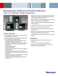
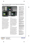
Multiformat, Multistandard Rasterizer
WVR7200 Data Sheet
New Tektronix-patented Spearhead display and Luma Qualified
Vector (LQV™) display facilitate precise color adjustment for
post-production applications (Opt. PROD)
Stereoscopic 3D Video Displays for Camera Alignment and
Production/Post-production Applications (Opt. S3D)
Black Picture and Tektronix-patented Frozen Picture Detection
Advanced ANC Data Monitoring
Simultaneous CEA708/608 Closed Caption monitoring; Teletext and
OP47 subtitle monitoring
Detect and decode ANC data including AFD, WSS, Video Index,
TSID, V-Chip, Broadcast Flag/CGMS-A, VITC, LTC, and ANC TC
ARIB STD-B35/B37/B39, TR-B22, and TR-B23 support
Features & Benefits
Multiformat, Multistandard Video Monitoring
WVR7200 includes standard auto-detection of HD/SD-SDI and
multiple Dual Link video formats
Composite analog (PAL/NTSC) video support (Opt. CPS)
Simultaneous monitoring (Opt. SIM) allows monitoring of 2
HD/SD-SDI inputs or 1 HD/SD-SDI input and 1 CPS input. Option 3G
is required for 3G-SDI format support
Multiple Input Mode allows monitoring of 2 to 4 SDI inputs
simultaneously (4-input mode requires Opt. 2SDI)
Upgradeable to 3G-SDI (Level A and Level B) format support
(Opt. 3G)
Comprehensive Audio Monitoring (Opt. AD or DPE)
Up to 16-channel audio monitoring for embedded audio
Multichannel Surround Sound*1 display and flexible Lissajous display
Audio Loudness monitoring to ITU-R BS.1770-2 (Opt. AD or DPE)
Support for analog, digital, and embedded audio (Opt. AD)
Dolby Digital (AC-3), Dolby Digital Plus, and Dolby E (Opt. DPE)
Comprehensive Dolby metadata decode and display (Opt. DPE)
Dolby E Guard Band meter with user-defined limits (Opt. DPE)
Unmatched Display Versatility
FlexVu™, the most flexible four-tile display, suited for various
application needs to increase productivity
Tektronix-patented Diamond and Arrowhead displays for gamut
monitoring
Tektronix-patented Timing and Lightning displays
In-depth Digital Data Analysis Helps Quickly Resolve Difficult Content
Quality and Reliability Issues (Opt. DAT)
Standard and User-definable Safe Area Graticules Facilitate Editing and
Format Conversion Tasks, Reducing the Need for Reworks
Active Format Description (AFD) Detection, Decode, and Automatically
Adjusted Graticule in Picture Display enable Easy Identification of
Aspect-ratio Related Issues
Superior Physical Layer Signal Measurement
High-performance real-time eye pattern display, jitter measurements,
and patented cable length measurement (Opt. PHY3)
Most comprehensive eye pattern measurements including eye
amplitude, rise/fall time, and overshoot/undershoot measurements as
well as Tektronix jitter waveform display (Opt. PHY3)
Unmatched Usability
CaptureVu® advanced video frame data capture simplifies
troubleshooting and equipment setup
32 instrument presets for quick recall of commonly used
configurations tailored to engineers or operators
Front-panel USB port enables easy transfer of presets, captured video
frame data, screenshots, and error log
Front-panel headphone port enables quick verification of selected
audio pair
Intuitive menu structure and context-sensitive help
Extensive alarms, status reporting, and error logging
SNMP and Ethernet remote interface capabilities and GPI control
facilitate centralized monitoring and control
Data Sheet
Loudness is a critical audio measurement to make for each produced
program and throughout the distribution chain. The WVR7200 includes
a Loudness meter as part of Option AD or DPE, with short and infinite
audio loudness measurements to ITU-R BS.1770-2 standard. Preset
configurations are defined to meet ATSC A/85, EBU R128, and
ARIB TR-B32 to suit the specific requirements of these standards. For
detailed analysis of loudness a graphical plot provides a Loudness Session
that can store up to 30 hours of data and can be downloaded for inclusion in
documentation using a network connection or USB device.
Multiformat support grows with your needs.
Applications
Monitoring and Compliance Checking in Content Distribution and
Broadcast transmission
Quality Control in Content Production and Post-production
Equipment/System Qualification and Troubleshooting for Installation and
Maintenance of Content Creation and Distribution Facilities
Post-production Edit Suite and Color Correction Monitoring
*1 Audio Surround Sound Display licensed from Radio Technische Werksütten GmbH and Co. KG (RTW).
WVR7200
The monitoring and measurement capabilities of the WVR7200 provide
a comprehensive suite of options and configurations to suit a variety of
applications. For monitoring applications Tektronix-patented gamut displays
simplify color adjustments for camera balancing and color correction
applications. Get information about the signal at a glance from the audio
session and video session displays that assist in ensuring quality control
of the image.
Tektronix provides an extensive audio toolset for monitoring analog, digital
AES/EBU, and digital embedded within Option AD. Up to 16 channels
of embedded audio can be monitored for bar levels, which allows the
operator to quickly check audio signal levels. Lissajous, Surround Sound*1,
and correlation meters show the interaction of the audio channels. For
Dolby Digital (AC-3), Dolby Digital Plus, and Dolby E, Option DPE
adds the additional functionality to decode the Dolby stream with a
comprehensive Dolby metadata decode and status display. To ensure
Dolby E synchronization the guard band meter easily shows the start of the
Dolby frame in relation to the video signal with user-defined limits.
2
www.tektronix.com
A variety of ancillary data is now carried within the SDI signal, and the ANC
data toolset of the WVR7200 can help monitor and troubleshoot problems
within the signal chain. The Aux Data Status display provides a summary of
critical ANC data such as closed captioning / subtitling, AFD, and time code.
The ANC Data Inspector allows the user to quickly verify the presence of
ANC data within the signal and the Datalist display allows inspection of the
data line by line, sample by sample.
For measurement of the physical layer the WVR7200 includes
high-precision eye and jitter displays that provide automated measurements
of amplitude, rise/fall times, overshoot/undershoot, and timing or alignment
jitter. The measurement functions of the WVR7200 also include options for
AV Delay and Stereoscopic 3D Monitoring, making the WVR7200 an ideal
choice for monitoring and measurement applications.
Video Monitoring Standards and Formats
Standard Definition SDI – Standard
High Definition SDI – Standard
Dual Link (4:2:2, 4:4:4, alpha channel, 10 bit, 12 bit) – Standard
Composite Analog Video – Option CPS
3G-SDI (Level A and Level B) – Option 3G
Multiple Input Mode, 4 SDI inputs – Option 2SDI
Color Gamut Monitoring
Arrowhead Display – Standard
Diamond and Split Diamond Displays – Standard
Spearhead Display – Option PROD
Luma Qualified Vector (LQV™) – Option PROD
Audio Monitoring Standards and Formats
Analog, Digital AES/EBU, Digital Embedded – Option AD
Analog and Digital including Dolby Digital, Dolby Digital Plus, and
Dolby E – Option DPE
Measurement and Analysis
Automated Eye Pattern and Jitter Measurements – Option PHY3
Color Bar and Pathological Signal Generation – Option GEN
Digital Data Analysis – Option DAT
ANC Data Inspector – Option DAT
Simultaneous Input Monitoring – Option SIM
Stereoscopic 3D Monitoring – Option S3D
Audio/Video Delay Measurement – Option AVD
Multiformat, Multistandard Rasterizer — WVR7200
A variety of Session and Status displays can be viewed at a glance with FlexVu™.
See and Solve™ with Tektronix Displays
Tektronix See and Solve™ displays simplify video monitoring tasks such as
calibration, error detection, and content correction allowing users to detect
errors at a glance and troubleshoot them efficiently.
Specialized Session and Status displays provide summarized yet
comprehensive reports of conditions and measurements of content
parameters.
The powerful Error Log is configurable by a variety of alarm conditions
such as black and frozen frame detection and provides detailed reports
for up to 10,000 events that can be downloaded using a web browser or
saved through a front-panel connection to a USB flash drive. Alarms can
also activate ground closures and SNMP traps, simplifying centralized
monitoring of multiple programs and allowing the operator to be alerted to
problems within the transmission chain.
The FlexVu™ four-tile display provides maximum flexibility to increase your
productivity. Unlike instruments with predetermined view combinations or
limited choices, FlexVu™ lets you create a multi-view display tailored to
your specific needs and work practices. Each tile can be configured to
enable easy signal analysis such as multiple alarm and status screens,
different Safe Area Graticules and cursors on each tile, and more.
Tektronix displays offer the sharpest CRT-like trace quality for clear
waveform and vector monitoring without pixelation distortions. The familiar
video waveform display can show SD, HD, or 3G-SDI (with Opt. 3G) signals
in RGB, YPbPr, YRGB, or composite formats. Signal components can
be displayed in either Parade or Overlay mode. For composite analog
video, NTSC and PAL signals can be displayed with luma, chroma, and
luma+chroma filtering.
Tektronix-patented Diamond, Spearhead, and Arrowhead gamut displays, along with the
Picture Bright-up display.
The Vector display offers user-selectable graticules, color targets (75% or
100%), and color axis.
Color Correction Toolset for Editors and Colorists
The Tektronix-patented Diamond, Split Diamond, and Arrowhead gamut
displays simplify the process of verifying gamut compliance.
The Diamond and Split Diamond displays help easily identify and correct
RGB gamut errors in digital video signals. The Arrowhead display saves
time in verifying composite gamut compliance for digital video signals.
User-selectable gamut thresholds let you tailor these displays and the
associated gamut alarms to your particular compliance standards. You can
also select bright-up conditions to easily see the location of gamut errors in
the picture display. Flexible Safe Area Graticules within the picture display
allow for quick placement of graphics, titles, or logos. Using FlexVu™, users
can see two or more pictures with different graticules.
The WVR7200 also features optional advanced color gamut monitoring
capabilities including the Tektronix-patented Luma Qualified Vector
(LQV™) display and Spearhead display (Opt. PROD) which, when used in
conjunction with Tektronix proprietary Diamond and Split Diamond gamut
displays, provide the most comprehensive color gamut monitoring tools
available for precise color gamut adjustments.
The combination of FlexVu™ and variety of gamut displays allow the
instrument to be customized for your individual application to meet your
needs. Additionally, simple presets can be set up and quickly recalled
allowing the user to rapidly switch from one configuration to another.
www.tektronix.com
3
Data Sheet
Simultaneous decode of CEA708 and CEA608 captions within multiple picture displays.
Content QA and Distribution Chain
The WVR7200 can be configured to alarm on a variety of errors within the
video and audio signal. Errors that occur within the program material can
be logged against time code, allowing an operator to quickly investigate
problems within the material. This can save time in evaluating quality
assurance issues within content and provide documentation of the list of
errors within the material that can be downloaded from the instrument using
a network connection or USB device.
The picture display provides detection and decode of CEA708/608 Closed
Caption. Using multiple picture displays, the instrument can decode
CEA708 and CEA608 simultaneously, allowing verification of the presence
and decoding of this critical metadata within one pass of the material.
Teletext subtitle pages can also be decoded in either 625 formats or
using OP47 ancillary data. Flexible Safe Area Graticules allow for quick
placement of graphics, titles, or logos. Using FlexVu™, users can see two
or more pictures with different graticules.
4
www.tektronix.com
Multiple Input mode display of four SDI inputs with input labels for each signal.
Black and frozen frame detection can provide indication when the signal is
lost during transmission and provide an alert of the alarm visually within the
video session or error log displays. Alternatively, a ground closure or SNMP
trigger can also be used to alert the operator to a problem.
Camera Balance Application
Within a studio or on-location within a truck it is important that all the
cameras are matched to ensure the look of the production from camera to
camera, scene to scene. With the Multiple Input mode of the WVR7200 the
instrument can be used to monitor up to four SDI inputs simultaneously
when in Full Screen mode (4-input mode requires Opt. 2SDI). This type of
display is ideal for camera balance applications where the user wishes to
check the video level across multiple inputs to ensure consistency of the
cameras’ output. This Multiple Input mode is available within Waveform,
Vector, Lightning, Diamond, Arrowhead, and Spearhead (with Opt. PROD)
display modes, allowing for the comparison of video inputs across a wide
variety of these displays.
Multiformat, Multistandard Rasterizer — WVR7200
Audio Monitoring with Lissajous display, Channel Status information, Loudness Session,
and Audio Session.
Complete Monitoring Tool Set for Optimum Sound
Quality
The WVR7200 provides high-quality digital filtering and oversampling to
insure precise, reliable, and repeatable audio measurements. For easy
monitoring, the WVR audio options provide format auto-detection and
flexible mapping of audio inputs to analog or digital audio outputs for
connection to external devices.
The Audio display provides a variety of display configurations for audio level
and phase monitoring. Up to 16 channels of embedded audio levels can be
monitored with a variety of scales and ballistics configured by the user. For
AES and embedded audio, eight audio channels can be monitored for audio
level with phase correlation meters. The Bars display provides indicators
for faults, audio levels, and Dolby format information. A Lissajous display
can be enabled for a selected channel pair and provides an X-Y plot of the
audio signals. The flexible Lissajous display allows the selection of any two
audio channels. The Surround Sound*1 display provides intuitive graphical
representation of channel interaction in a system.
Loudness monitoring is becoming a critical part of audio monitoring of the
program to ensure consistent audio loudness levels between programs and
commercials. Loudness measurements are made to ITU-R BS.1770-2. A
Loudness meter is available within the Audio display that provides Short and
Infinite Loudness measurements. Within the configuration menu there are
simple Loudness presets for the various standards such as ATSC A/85,
EBU R128, and ARIB TR-B32. The Loudness session display graphically
Dolby Audio Monitoring with Surround Sound display, Dolby Status, Audio Session, and
Loudness Session displays.
plots Loudness measurements over time, from 90 seconds to 30 hours.
The Loudness measurements can be downloaded through the network or
saved to USB for further analysis.
Specialized audio displays provide deeper inspection of the signal and
make the WVR7200 instrument the most comprehensive waveform and
audio monitor available. The Audio Session displays summarize levels,
faults, and number of active bits for each channel. These instruments also
feature Audio Control Packet Data and Channel Status displays.
Dolby Audio Monitoring
Option DPE of the WVR7200 supports decoding of Dolby Digital (AC-3),
Dolby Digital Plus, and Dolby E, providing decoding of up to 10 audio bar
level meters along with correlation meters of the Dolby data stream. The
decoded Dolby stream can be flexibly mapped to the analog or digital audio
outputs.
The Dolby Status display (Opt. DPE) gives an in-depth view of integrated
or VANC metadata and comparisons of the Dialnorm value to Loudness
measurements. Dolby E requires frame synchronization to the video signal
and the guard band measurement provides a direct readout in terms of
field and line location of the Dolby frame sequence. User-configurable
thresholds for the Dolby E guard band timing measurement (Opt. DPE) are
available as well as Dolby E guard band timing and trigger alarms based on
their specific guard band parameters.
*1 Audio Surround Sound Display licensed from Radio Technische Werksütten GmbH and Co. KG (RTW).
www.tektronix.com
5
Data Sheet
Simultaneous Input mode of WVR7200 comparing incoming and outgoing signals.
Full-featured Simultaneous Input Monitoring Boost
Versatility
The Simultaneous Input Monitoring (Opt. SIM) capability of the WVR7200
takes multiformat monitoring to a new level. This capability helps
operational staff quickly determine if a video quality problem existed in the
input signal or arose in their facility. It enables engineering staff to quickly
detect, diagnose, and resolve technical problems introduced in a piece of
video equipment by comparing the input and output signals at each point
in the chain. This feature is also especially helpful when checking for
transparency during format conversion.
FlexVu™ enables flexible and intuitive configuration of displays from two
monitored inputs. The user can display simultaneous fault detection, status
reporting, alarm generation, and error logging. SIM is ideal for transmission
monitoring of simultaneous HD and SD programs. It is also ideal for
monitoring stereoscopic 3D content in production and post-production
applications by simultaneously monitoring the Left Eye image and the Right
Eye image.
SyncVu™ is used in conjunction with SIM mode for 3D applications when
input A is used for the Left Eye and input B is used for the Right Eye. When
SyncVu™ is enabled, the Left and Right Tile displays are synchronized,
so that if a picture tile is selected for Tile 1, Tile 2 automatically displays
a picture tile in exactly the same mode as Tile 1. This enables the user
to quickly configure the instrument identically for Left and Right Eye 3D
monitoring.
The CaptureVu® feature on the WVR7200 allows users to capture, store,
and download the data of a video frame to recreate displays and compare
the live signal to captured data for easy troubleshooting of intermittent errors
or for analyzing fault conditions at remote sites.
6
www.tektronix.com
Simultaneous 3D display of Left Eye and Right Eye signals with Difference Map and
Overlay picture displays.
3D Stereoscopic Monitoring
The 3D stereoscopic monitoring and displays are available on WVR7200
with Option S3D. A 3D image is comprised of a Left Eye and Right Eye
image to be fed as two separate HD-SDI signals or combined within a
3G Level B format. Alternatively, the 3D signal can be carried in a single
HD-SDI signal as a Side by Side or Top/Bottom image for the left and right
images. A variety of different 3D monitoring modes are available within
the instrument to assist the user in determining the difference between the
Left Eye and Right Eye views. From this disparity difference between the
two left and right images, the depth of an object within the image can be
determined.
For monitoring purposes a variety of displays can be set up within the
Picture mode:
Difference Map Display – A subtraction of the two luma video signals
L-R or R-L to produce a grayscale difference map image and see the
difference between the left and right images
Red/Cyan Anaglyph Display – The left image is shown in red and the
right image is shown in cyan, with identical left and right objects shown in
monochrome. This allows the user to isolate differences between objects
and gauge the depth of the object within the image
Green/Magenta Anaglyph Display – The left image is shown in green
and the right image is shown in magenta, with identical left and right
objects shown in monochrome
Checkerboard Display – This picture display shows a block of the image
from the left eye and then the next block shows the image from the right
eye in a 16×9 checkerboard pattern. This helps the user compare the
levels and color of the signal between the left and right images
These modes help the user compare the disparity between the left and right
images and can assist in interpreting the depth of the objects within the
image.
Multiformat, Multistandard Rasterizer — WVR7200
3D Left and Right Eye RGB waveform displays with a Checkerboard, and Red/Cyan
Anaglyph picture displays.
3D Stereoscopic Measurement
For measurement of the depth of an object within the image (Opt. S3D) a
Disparity Grid can be overlaid over the picture with a horizontal disparity
between 1 to 15% of screen width and a vertical disparity of 50%, 25%, or
10% that can be selected by the user. The horizontal and vertical position
controls allow the Disparity Grid to be moved around within the picture
display to gauge the depth of objects within the image.
A set of Disparity Cursors are also available for precise measurement of
horizontal disparity of an object between the Left and Right Eye images.
Readout is given of the pixel difference between the cursors and the
percentage of disparity of an object.
Quad Diamond display of Left and Right Eye Disparity for Luma, Red, Green, and Blue
components.
Quad Diamond Display for 3D Alignment
The new Tektronix-patented Quad Diamond display (Opt. S3D) simplifies
stereoscopic camera alignment by viewing a disparity histogram of the left
and right signal from a signal level of 0 to 100% vertically for each of the
components: Luma, Red, Green, and Blue. If the two cameras are well
balanced the trace will form a vertical trace for each of the diamonds. A
deviation in the trace indicates an imbalance between the left and right eye
images that should be corrected using the various camera controls until the
trace becomes vertical. This display can also be used in post-production for
aiding the editor and perform color correction on the left and right images.
www.tektronix.com
7
Data Sheet
ANC Data Inspector and CaptureVu provide detailed content analysis.
Datalist display provides detailed pixel-by-pixel information.
Video Index Aspect Ratio, Wide Screen Signaling (WSS), V-Chip, TSID,
CGMS-A, Broadcast Flag, CEA708/608 Closed Caption, Teletext, and Time
Code information.
Today there is a wide array of metadata that provides information to a
variety of equipment through the processing chain. Monitoring of this
metadata is critical to ensure that the processing equipment correctly
handles the signal. For instance, correct format of the AFD ensures that the
aspect ratio on the display is correctly formatted and the automated AFD
graticule is available for the picture display of the WVR7200 along with the
binary data and text description for easy monitoring.
The WVR7200 can also monitor Dolby metadata embedded in the Vertical
Ancillary (VANC) data space per SMPTE 2020.
Monitoring of ancillary data (Closed Caption, Time Code, and AFD) using Aux Data
Status.
Superior Data Analysis Capabilities for Engineers and
Operators
The ANC Data Inspector (Opt. DAT) provides an industry-leading solution to
help broadcasters easily and accurately ensure that all required VANC data
is present and correctly configured through an intuitive ANC data display.
In contrast to other solutions, the ANC Data Inspector enables operators to
easily and quickly ensure that the VANC data is present and free of errors.
When errors are detected, engineers are quickly guided to a more detailed
view of the data packet content for further analysis.
With FlexVu™, each picture display tile can display different CEA708/608
Closed Caption and individual Teletext subtitles. Teletext subtitle pages can
be decoded in either WST or OP47 format.
The Auxiliary Data Status display (standard on the WVR7200) provides
summary information on Active Format Description (AFD) per SMPTE 2016,
8
www.tektronix.com
The Datalist display (Opt. DAT) provides detailed information on the actual
data values in HD/SD-SDI and 3G-SDI (with Opt. 3G) input signals. Users
can easily use this display to locate protocol errors in the input signals.
The right side of the display shows the data values in hexadecimal, decimal,
or binary format and uses the following color coding for easy identification of
data types and errors:
Green – Active video data
Blue – Data in horizontal or vertical blanking intervals
White – EAV, SAV, and other reserved words
Yellow – Data outside nominally allowed values
Red – Data with illegal values
The left side of the display shows un-interpolated digital values plotted
against sample numbers as a digital waveform. You can configure this
unique display in either Video mode or Data mode.
In Video mode, the display shows the Y, Cb, Cr values aligned temporally,
but offset vertically. Like the waveform display, you can configure the
display to show one, two, or all three components.
Multiformat, Multistandard Rasterizer — WVR7200
Eye and Jitter display along with automated measurements of physical layer parameters.
Physical Layer Measurements
The WVR7200 rasterizer offers comprehensive physical-layer signal
measurements for engineers when Option PHY3 is installed.
The HD/SD-SDI eye pattern display, jitter measurements, and cable
length measurements provide essential analysis of the physical layer. An
easy-to-interpret gauge provides direct readout of jitter measurements
for timing or alignment jitter with various user-selectable jitter filters from
10 Hz to 100 kHz within the eye display. Users can configure timing jitter
and alignment jitter readouts to be displayed simultaneously to effectively
isolate the sources of jitter. The SDI Status display summarizes key signal
parameters such as signal strength, cable loss, and Tektronix-patented
estimated cable length measurements. With Option 3G the WVR7200 is
also capable of displaying 3G physical layer measurements, allowing the
instrument to support your future requirements.
With FlexVu™, users can simultaneously display timing jitter and alignment
jitter values, cable parameter measurements, and display different eye
patterns to help quickly diagnose and resolve problems related to SDI timing
jitter or cable attenuation. The Infinite Persistence mode of the rasterizer
can also be used to more easily view the eye opening of the physical layer
signal.
In addition, the WVR7200 (with Opt. PHY3) can also perform automated
eye amplitude, automated rise/fall time, automated overshoot/undershoot
measurements, and provide a jitter waveform display to view jitter related
to line and field rates. All these capabilities help broadcasters and
network operators detect and diagnose signal quality problems quickly and
efficiently.
Option GEN on the WVR7200 provides a simple test signal generator output
that creates 100% Color Bars, 75% Color Bars, and Pathological Test
signals for a variety of video formats that can be used to verify signal path.
Timing and Lightning displays simplify timing tasks.
Facility Timing Made Easy
Audio/Video synchronization is an important challenge in the processing of
video signals. The WVR7200 with Option AVD displays the A/V delay on a
graphical bar indicator. The measurement readout gives facility engineers
the necessary tools to ensure system integrity and facilitate A/V delay
compliance. This feature provides out-of-service measurement of A/V
delay for analog or digital audio and video formats. A TG700 is required to
generate the SDI signal which contains the audio and video sequence that
can be distributed through the system and measured by the WVR7200.
The Tektronix-patented Timing display makes facility timing easy through a
simple graphical representation which shows the relative timing of the input
signal and the reference signal (or a saved offset reference) on an X-Y axis.
The Lightning display shows luma and chroma amplitudes and helps users
verify component timing using a color bar signal. The Tektronix-patented
Bowtie display (standard on the WVR7200) complements the timing
measurement capability of the Lightning display. Using a special Bowtie test
signal in component format, this display helps make precise and accurate
measurements of inter-channel amplitude and timing. The SCH Phase
display helps quickly verify this critical timing parameter of composite analog
video signals.
Remote Front Panel
The WVR7200 can be controlled by the newly designed remote front panel
(WVR8RFP) which has the same control button and knob configuration
as the front panel on the instrument. The remote front panel (WVR8RFP)
allows operators to access and control the WVR7200 from a distance of up
to 1000 ft. with power supplied from the base instrument through the cable.
Users can also choose to connect the remote front panel with an external
12 V DC power source which can extend the distance of the cable run to
4000 ft.
www.tektronix.com
9
Data Sheet
Video Input and External Reference Formats Supported
Automatic Detection of a Wide Range of Signal Formats
The WVR7200 rasterizer accepts a wide variety of input signal formats and external references. The rasterizer will automatically detect the signal format and establish
the appropriate settings for the various displays.
Setting
NTSC,
59.94 Hz
PAL,
50 Hz
BT601
483i,
59.94 Hz
(525)
BT601
576i,
50 Hz
(625)
296M
720p,
23.98 Hz
296M
720p,
24 Hz
296M
720p,
25 Hz
296M
720p,
29.97 Hz
296M
720p,
30 Hz
296M
720p,
50 Hz
296M
720p,
59.94 Hz
296M
720p,
60 Hz
240M
1035i,
59.94 Hz
240M
1035i,
60 Hz
274M
1080i,
50 Hz
274M
1080i,
59.94 Hz
274M
1080i,
60 Hz
274M
1080p,
23.98 Hz
274M
1080p,
24 Hz
274M
1080p,
25 Hz
10
Opt.
CPS
STD SD STD HD
Bi-level Sync
PAL
NTSC
X
Tri-level 720p
50 Hz
59.94
Hz
External Reference Inputs
Tri-level 1080p
60 Hz
23.98
Hz
24 Hz
Tri-level 1080i
50 Hz
59.94
Hz
60 Hz
1080 SF
23.98
24 Hz
Hz
X
X
X
X
X
X
www.tektronix.com
X
X
X
X
X
X
X
X
X
X
X
X
X
X
X
X
X
X
X
X
X
X
X
X
X
X
X
X
X
X
X
X
X
X
X
X
X
X
X
X
X
X
X
X
X
X
X
X
X
X
X
X
X
X
X
X
X
X
X
X
X
X
X
X
X
X
X
X
X
X
X
X
X
X
X
X
X
X
Multiformat, Multistandard Rasterizer — WVR7200
Setting
274M
1080p,
29.9 Hz
274M
1080p,
30 Hz
274M
1080sf,
23.9 Hz
274M
1080sf,
24 Hz
274M
1080sf,
25 Hz
274M
1080sf,
29.9 Hz
274M
1080sf,
30 Hz
Opt.
CPS
STD SD STD HD
Bi-level Sync
PAL
NTSC
X
Tri-level 720p
50 Hz
59.94
Hz
X
X
24 Hz
Tri-level 1080i
50 Hz
59.94
Hz
X
X
X
X
1080 SF
23.98
24 Hz
Hz
X
X
X
60 Hz
X
X
X
X
X
X
X
X
X
X
X
X
Supported Dual Link Formats
Format
23.98
Hz
X
X
X
60 Hz
X
X
X
External Reference Inputs
Tri-level 1080p
X
Supported 3G Single Link Formats
Sample Structure
Frame/Field Rates
1920 × 1080
4:2:2 YCbCr 10 bit
2048 × 1080
4:4:4 RGB
4:4:4:4 RGB +A 10 bit
4:4:4 RGB 12 bit
4:4:4 YCbCr 10 bit
4:4:4:4 YCbCr +A 10 bit
4:4:4 YCbCr 12 bit
4:2:2 YCbCr 12 bit
4:2:2:4 YCbCr +A 12 bit
4:4:4 RGB
4:4:4:4 RGB +A 10 bit
4:4:4 RGB 12 bit
4:4:4 YCbCr 10 bit
4:4:4:4 YCbCr +A 10 bit
4:4:4 YCbCr 12 bit
4:2:2 YCbCr 12 bit
4:2:2:4 YCbCr +A 12 bit
4:4:4 XYZ 12 bit
60, 60/1.001, and 50
progressive
30, 30/1.001, 25, 24 and
24/1.001 progressive,
PsF 60, 60/1.001, and 50
fields interlaced
Format
Sample Structure
Frame/Field Rates
50, 59.94, 60 progressive
2 × HD
1920 × 1080
4:2:2 YCbCr 10 bit
Level A and Level B
4:2:2 YCbCr 10 bit
Level B
4:4:4 YCbCr 10 bit
4:4:4:4 YCbCrA 10 bit
Level B
4:4:4 RGB 10 bit
4:4:4:4 RGB +A 10 bit
Level B
4:4:4 RGB 12 bit
Level B
4:2:2 YCbCr 12 bit
4:2:2:4 YCbCrA 12 bit
Level B
4:4:4 YCbCr 12 bit
Level B
4:4:4 RGB 12 bit
Level B
4:4:4 XYZ 12 bit
Level B
4:2:2 YCbCr 10 bit
Level B
2 × HD
1280 × 720
4:2:2 YCbCr 10 bit
Level B
3G-SDI Formats
Dual Link
Single Link
1920 × 1080
30, 30/1.001, 25, 24, and
24/1.001 progressive, PsF
2048 × 1080
23.98, 23.98sF, 24, 24sF,
25, 25sF 29.97, 29.97sF,
30, 30sF progressive 50,
59.94, 60 interlaced
23.98, 23.98sF, 24, 24sF,
25, 25sF, 29.97, 29.97sF,
30, 30sF progressive
23.98, 23.98sF, 24, 24sF,
25, 25sF, 29.97, 29.97sF,
30, 30sF progressive 50,
59.94, 60 interlaced
23.98, 24, 25, 29.97, 30,
50, 59.94, 60 progressive
www.tektronix.com
11
Data Sheet
Characteristics
Composite Video Interface (Option CPS)
Characteristic
Description
Formats Supported
Inputs
Input Type
Input Dynamic
Range
Maximum Operating
Amplitude
Absolute Maximum
Input Voltage
DC Input
Impedance
Return Loss
NTSC, NTSC no setup, PAL
2, only 1 active at a time
Passive loopthrough BNC, 75 Ω compensated
±6 dB (typical)
Crosstalk between
Channels
Loopthrough
Isolation
DC Offset with
Restore Off
DC Restore
Attenuation
Slow Mode
Lock Range
–1.8 V to +2.2 V, DC + peak AC (typical)
–6.0 V to +6.0 V, DC + peak AC
20 kΩ, nominal
>40 dB to 6 MHz, power on (typical)
>40 dB to 10 MHz (typical)
>46 dB to 6 MHz (typical)
35 dB, power off (standard amplitude video)
>60 dB to 6 MHz (typical)
>70 dB to 6 MHz (typical)
<20 mV (typical)
50 Hz and 60 Hz
Fast mode >95% attenuation
Slow mode <10% attenuation
<10% peaking
Typical peaking 8% at 50 Hz and 60 Hz
±50 ppm remains locked
External Reference
Characteristic
Description
Input Type
DC Input
Impedance
Return Loss
Passive loopthrough BNC, 75 Ω compensated
15 kΩ, typical
>40 dB to 6 MHz, >35 dB to 30 MHz (typical)
Frequency Response
Characteristic
HD
Luminance
Channel (Y)
Chrominance
Channels
(Pb, Pr)
SD
Luminance
Channel (Y)
Chrominance
Channels
(Pb, Pr)
Description
50 kHz to 30 MHz ±0.5%
50 kHz to 15 MHz ±0.5%
50 kHz to 5.75 MHz ±0.5%
50 kHz to 2.75 MHz ±0.5%
Analog Composite Waveform Vertical Characteristics
(Option CPS)
Characteristic
Description
Vertical
Measurement
Accuracy
Gain
Frequency
Response
±1% all gain settings
X1, X2, X5, and X10
Flat to 5.75 MHz, ±1%
Waveform Horizontal Sweep Characteristics
Characteristic
Description
Sweep Timing
Accuracy
Sweep Linearity
±0.5%, all rates, fully digital system
0.2% of time displayed on-screen, fully digital system
Vector Characteristics
Characteristic
Description
Vector Amplitude
Accuracy
Vector Phase
Accuracy
±2%
±2°
Audio Characteristics (Optional Capability)
Monitor Display Output
Characteristic
Description
1024×768, 60 Hz vertical rate
Signal Format*2
(XGA DVI-I Output)
*2 External display required.
Serial Digital Waveform Vertical Characteristics
Characteristic
Description
Vertical
Measurement
Accuracy
Gain
At 1X, ±0.5%
At 5X, ±0.2% of 700 mV full-scale mode
12
X1, X2, X5, and X10
www.tektronix.com
Characteristic
Description
Level Meter
0.056 dB steps at 30 dB scale, from full scale to –20 dBFS
Resolution
User-selectable Scales
Analog
dBu, Din, Nordic, VU, IEEE PPM, BBC Scale, and user
definable
Digital
dBFS, Din, Nordic, VU, IEEE PPM, BBC Scale, and user
definable
Meter Ballistics
Selectable from true peak, PPM Type 1, PPM Type 2, and
Extended VU
Mute, clip, user-programmable silence, over
Defined/
Programmable
Level Detection
Multiformat, Multistandard Rasterizer — WVR7200
Digital Audio (Option DPE and AD)
Physical Characteristics
Characteristic
Description
Dimension
mm
in.
Inputs
Two sets with 8 channels each, 32-192 kHz, 24 bit. Meets
requirements of AES 3-ID and SMPTE 276M-1995
BNC, 75 Ω terminated, unbalanced, 0.2 Vp-p to 2 Vp-p
Height
Width
Depth
44
483
498
1.725
19
19.625
Input
Characteristics
Input Return Loss
Outputs
>25 dB relative to 75 Ω from 0.1 MHz to 6 MHz (typical)
Up to 8 channels, AES 3-ID output, 48 kHz 20 bit for
SD embedded, 48 kHz 24 bit for HD embedded, 48 kHz
24 bit for analog to AES. For AES to AES loopthrough,
output format equals input format. Meets requirements of
SMPTE 276M-1995 (AES 3-ID). For decoded Dolby Digital,
output is 24 bits at a rate of 32, 44.1, or 48 kHz for any one
decoded pair. For decoded Dolby E, the output is 24 bits at
48 kHz or 47.952 kHz for up to 4 Luminance Channel 50 kHz
to 30 MHz ±0.5% pairs
Output
BNC, 75 Ω terminated, unbalanced, 0.9 Vp-p to 1.1 Vp-p
Characteristics
Chrominance 50 kHz to 15 MHz ±0.5% into 75 Ω
Output Return Loss >25 dB relative to 75 Ω from 0.1 MHz to 6 MHz (typical)
Output Jitter
3.5 ns, peak, typical, with 700 Hz high-pass filter per
Luminance Channel 50 kHz to 5.75 MHz ±0.5% AES
specification (typical)
Level Meter
+0.1 dB from 20 Hz to 20 kHz, 0 dBFS to –40 dBFS, sine
Accuracy over
wave, Peak Ballistic mode (except for within 5 Hz of some
Frequency
submultiples of the sampling frequency)
Analog Audio (Option DPE and AD)
Characteristic
Description
Analog Inputs
2 sets of 6 channels each
Analog Input
Balanced, unterminated through the rear-panel connector
Characteristics
<90 dB
Crosstalk
Input Impedance
24 k, typical
8 channels
Analog Outputs
Analog Output Characteristics
Balanced
Unterminated through the rear-panel connector
Maximum Output Level
Balanced
+24 dBu ±0.5 dB
Digital Input to
±0.5 dB, 20 Hz to 20 kHz, –40 dBFS, 20 bit or 24 bit inputs
Analog Output
Gain Accuracy over
Frequency
+0.8 dB, 20 Hz to 20 kHz, 24 dBu to –16 dBu
Analog Input to
Analog Output
Gain Accuracy over
Frequency
Output Impedance 50 Ω nominal
Power
Characteristic
Description
Weight
kg
lb.
Net
Shipping
4.3
8.5
9.5
18.5
WVR8RFP
Dimension
mm
in.
Height
Width
Depth
44
483
114
1.725
19
4.5
Capabilities by Optional Configuration
WVR7200
Capability
Video Formats and Inputs
HD-SDI / Dual Link /
SD-SDI
3G-SDI (Level A and
Level B)
4 SDI Input Monitoring
Composite PAL/NTSC
Standard
Option 3G
Option 2SDI
Option CPS
Audio Formats and Inputs
Embedded and AES
Digital Audio
Analog Audio
Dolby E / Dolby Digital
Plus / Dolby Digital
Option AD or DPE
Option AD or DPE
Option DPE
Physical Layer Measurement
Jitter Measurements
Eye Pattern Display
Eye Pattern Auto
Measurements
Pathological Signal
Generation
Option PHY3
Option PHY3
Option PHY3
Option GEN
Other Advanced Capabilities
Advanced Color Gamut
(Spearhead / LQV)
Simultaneous Input
Monitoring (SIM)
3D Video Monitoring
ANC Data Inspector
Digital Data Analysis
Out-of-Service AV Delay
Measurement
Option PROD
Option SIM
Option S3D
Option DAT
Option DAT
Option AVD
Power Consumption 110 W maximum
Voltage Range
100 to 240 V AC ±10%; 50/60 Hz
www.tektronix.com
13
Data Sheet
Ordering Information
Note: Please specify power plug when ordering.
Product Nomenclature and Descriptions
Model
Option
WVR7200
Description
SDI Rasterizer, 2 SDI inputs (Auto-detection of SDI format)
Base unit includes HD-SDI, SD-SDI, Dual Link signal formats
CPS*3
3G
SIM
2SDI*3
PROD
DAT
PHY3
GEN
AVD
S3D
AD
DPE
62
Option 3G required for 3G-SDI support
Add support for composite analog video monitoring; 2 composite analog inputs; passive loopthrough
Add support for 3G-SDI signal formats
Add simultaneous monitoring of 2 HD/SD-SDI inputs or 1 HD/SD-SDI input and 1 CPS input
Option 3G required for 3G-SDI formats support
Adds additional SDI module (in Slot 2) to support up to 4 SDI inputs within Multi Mode displays (3G-SDI,
HD-SDI, and SD-SDI support on the same inputs – auto-detect)
Option 3G required for 3G-SDI support
Advanced Gamut Monitoring Package (Spearhead gamut display and Luma Qualified Vector display)
Add Advanced HD/SD-SDI Data Analyzer and Ancillary Data Analyzer
Option 3G required for 3G-SDI formats support
Physical Layer Measurement Package (includes HD-SDI, and SD-SDI eye pattern and jitter waveform displays;
automated measurements of eye pattern parameters, jitter, and cable parameters)
Option 3G required for 3G-SDI support
Add HD/SD-SDI Color Bar and Pathological Signal generation capability
Option 3G required for 3G-SDI signal generation capability
Add support for out-of-service A/V delay measurements; An audio option must also be ordered
Add Monitoring Support for Stereoscopic 3D Video (including Simultaneous Input Monitoring Capability)
Add analog audio monitoring (2 sets of 6-channel analog audio inputs and 8-channel analog audio outputs) plus
16 channels embedded or AES/EBU digital audio support (8 channels at a time) including loudness monitoring
Add Option AD capabilities (analog and digital audio – embedded or external AES) plus support for decoding
and monitoring Dolby E, Dolby D, and Dolby Digital Plus including loudness monitoring
Analog Audio Breakout Cable, 6 feet, male 62-pin connectors to 8 XLR male output connectors
and 12 XLR female input connectors
Additional Options
WVR8RFP
Remote front panel allows control of WVR7200 front panel at up to a distance of 1000 ft. An
external 12 V DC power supply allows control up to 4000 ft.
*3 Option 2SDI and Option CPS cannot be installed on the same instrument.
International Power Plugs
Option
Description
Opt.
Opt.
Opt.
Opt.
Opt.
Opt.
Opt.
Opt.
Opt.
Opt.
A0
A1
A2
A3
A5
A6
A10
A11
A12
A99
North America power
Universal Euro power
United Kingdom power
Australia power
Switzerland power
Japan power
China power
India power
Brazil power
No power cord or AC adapter
14
www.tektronix.com
Multiformat, Multistandard Rasterizer — WVR7200
Post Sale Upgrade Options
Model
WVR720UP
Option
Description
CPS*3
Add support for composite analog video monitoring; 2 composite analog inputs; passive loopthrough
Add support for 3G-SDI signal formats
Add simultaneous monitoring of 2 HD/SD-SDI inputs or 1 HD/SD-SDI input and 1 CPS input
3G
SIM
2SDI*3
PROD
DAT
PHY3
GEN
AVD
S3D
AD
DPE
62
Option 3G required for 3G-SDI formats support
Adds additional SDI module (in Slot 2) to support up to 4 SDI inputs within Multi Mode displays (3G-SDI,
HD-SDI, and SD-SDI support on the same inputs – auto-detect)
Option 3G required for 3G-SDI support
Advanced Gamut Monitoring Package (Spearhead gamut display and Luma Qualified Vector display)
Add Advanced HD/SD-SDI Data Analyzer and Ancillary Data Analyzer
Option 3G required for 3G-SDI formats support
Physical Layer Measurement Package (includes HD-SDI, and SD-SDI eye pattern and jitter waveform displays;
automated measurements of eye pattern parameters, jitter, and cable parameters)
Option 3G required for 3G-SDI support
Add HD/SD-SDI Color Bar and Pathological Signal generation capability
Option 3G required for 3G-SDI signal generation capability
Add support for out-of-service A/V delay measurements; An audio option must also be ordered
Add Monitoring Support for Stereoscopic 3D Video (including Simultaneous Input Monitoring Capability)
Add analog audio monitoring (2 sets of 6-channel analog audio inputs and 8-channel analog audio outputs) plus
16 channels embedded or AES/EBU digital audio support (8 channels at a time) including loudness monitoring
Add Option AD capabilities (analog and digital audio – embedded or external AES) plus support for decoding
and monitoring Dolby E, Dolby D, and Dolby Digital Plus including loudness monitoring
Analog Audio Breakout Cable, 6 feet, male 62-pin connectors to 8 XLR male output connectors
and 12 XLR female input connectors
*3 Option 2SDI and Option CPS cannot be installed on the same instrument.
Service Options
Option
Description
Opt.
Opt.
Opt.
Opt.
Opt.
Opt.
Calibration Service 3 Years
Calibration Service 5 Years
Calibration Data Report
Calibration Data Report 3 Years (with Opt. C3)
Calibration Data Report 5 Years (with Opt. C5)
Complete Care 3 Years (includes loaner, scheduled
calibration and more)
Complete Care 5 Years (includes loaner, scheduled
calibration and more)
Repair Service 3 Years (including warranty)
Repair Service 5 Years (including warranty)
Repair Service Coverage 5 Years (includes product warranty
period). 5-year period starts at time of customer instrument
purchase. This option is available if the instrument is within
product warranty. It is not available once instrument exits
warranty period
Repair Service Coverage 3 Years (includes product warranty
period). 3-year period starts at time of customer instrument
purchase. This option is available if the instrument is within
product warranty. It is not available once instrument exits
warranty period
C3
C5
D1
D3
D5
G3
Opt. G5
Opt. R3
Opt. R5
Opt. R5DW
Opt. R3DW
www.tektronix.com
15
Data Sheet
Contact Tektronix:
ASEAN / Australasia (65) 6356 3900
Austria 00800 2255 4835*
Balkans, Israel, South Africa and other ISE Countries +41 52 675 3777
Belgium 00800 2255 4835*
Brazil +55 (11) 3759 7627
Canada 1 800 833 9200
Central East Europe and the Baltics +41 52 675 3777
Central Europe & Greece +41 52 675 3777
Denmark +45 80 88 1401
Finland +41 52 675 3777
France 00800 2255 4835*
Germany 00800 2255 4835*
Hong Kong 400 820 5835
India 000 800 650 1835
Italy 00800 2255 4835*
Japan 81 (3) 6714 3010
Luxembourg +41 52 675 3777
WVR7200 Front Panel and Remote Panel.
Mexico, Central/South America & Caribbean 52 (55) 56 04 50 90
Middle East, Asia, and North Africa +41 52 675 3777
The Netherlands 00800 2255 4835*
Norway 800 16098
People’s Republic of China 400 820 5835
WVR7200 Rear Panel.
Poland +41 52 675 3777
Portugal 80 08 12370
Republic of Korea 001 800 8255 2835
Tektronix is registered to ISO 9001 and ISO 14001 by SRI Quality System Registrar.
Russia & CIS +7 (495) 7484900
South Africa +41 52 675 3777
Spain 00800 2255 4835*
Sweden 00800 2255 4835*
Switzerland 00800 2255 4835*
Taiwan 886 (2) 2722 9622
United Kingdom & Ireland 00800 2255 4835*
USA 1 800 833 9200
* European toll-free number. If not accessible, call: +41 52 675 3777
Updated 10 February 2011
For Further Information. Tektronix maintains a comprehensive, constantly expanding
collection of application notes, technical briefs and other resources to help engineers working
on the cutting edge of technology. Please visit www.tektronix.com
Copyright © Tektronix, Inc. All rights reserved. Tektronix products are covered by U.S. and foreign patents,
issued and pending. Information in this publication supersedes that in all previously published material.
Specification and price change privileges reserved. TEKTRONIX and TEK are registered trademarks of
Tektronix, Inc. All other trade names referenced are the service marks, trademarks, or registered trademarks
of their respective companies.
13 Dec 2011
www.tektronix.com
2PW-27631-0