1
SENECA
III
PILOT'S
INFORMATION
MANUAL
Seneca lif
Published by
PUBLICATIONS
DEPARTMENT
Piper Aircraft Corporation
Issued: January 8, 1981
REPORT:
ii
VB-1110
APPLICABILITY
of this handbook is limited to the specific Piper PA-34-220T
Application
number on the
designated
by serial number and registration
model airplane
handbook.
of
this
title
of
the
face
page
This handbook cannot
be used for operational
purposes unless kept in
status.
a current
REVISIONS
compiled in the Pilors Operating Handbook, with the
list, will be kept current by revisions distributed
exception of the equipment
equipment list was current at the tinie the airThe
to the airplane owners.
maintained
plane was licensed by the manufacturer and thereafter must be
by the owner.
The information
Revision material will consist of information necessary to update the
handbook and/or to add information to cover added
text of the present
airplane
equipment.
L
Revisions
will be distributed whenever
necessary
as complete page
the handbook in
shall
inserted
and
additions
into
be
or
with the instructions given below:
Revisions
replacernents
accordance
1.
2.
3.
Revision pages will replace only pages with the same page number,
order within each
Insert all additional pages in proper numerical
section.
followed by a small letter shall be inserted in direct
Page numbers
numbered
page.
sequence with the same common
IL Identification
of Revised Material
Revised text and illustrations shall be indicated by a black vertical
revised, added or
margin of the page, opposite
line along the outside
deleted material. A line along the outside margin of the page opposite the
entire page was added.
page number will indicate that an
REPORT: VB-1110
lii
with changes
and
Black lines will indicate only current revisions
additions
Changes in
to or deletions of existing text and ilustrations.
capitalization.
spelling, punctuation or the physical location of material on
wil
not be identified
a page
ORIGINAL
The original
below:
PACES
ISSUED
pages issued for this handbook
prior to
revision
are
given
I-I I, 2-1 through 2-12, 3-1 through
Title, ii through vii. 1-I through
3-23. 4-1 through 4-37, 5-1 through 5-31, 6-1 through 6-68, 7-l through 7-39,
1()-3.
8-1 through 8-19, 9-1 through 9-102, and 10-1 through
REPORT:
iv
VB-Ille
OPERATING
PILOT'S
Current Revisions
book. REPORT:
Revised
Pages
Rev. 1
3-4
3-15
4-9
4-26
5-21
6-40
I
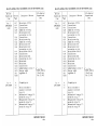
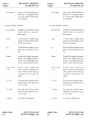
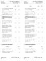
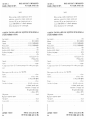
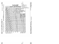
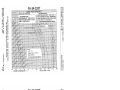
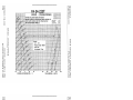
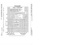
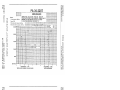
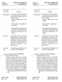
LOG OF REVISIONS
to the PA-34-220T Seneca [11 Pilot's Operating HandVB-1110 issued January 8. 1981.
Number and
Code
(PR8l0421)
HANDBOOK
6-48
6-49
7-14
7-26
9-i
9-19
thru
9-32b
Description
Revised
Revised
Revised
Revised
Revised
of Revision
FAA Approval
Signature and
Date
Warning.
Warning,
procedure.
para. 4.31.
fig. 5-21.
items 221 and 223.
Revised item 285.
Revised item 29 L
Revised para. 7.15.
Revised para. 7.23.
Revised Table of Contents.
Added Supplement 4
(KFC 200 Automatic Flight
Control System with Flight
Added
Director).
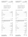
9-33
thru
9-44d
9-68
9-103
thru
9-106
9-107
thru
9-112
9-113
thru
9-124
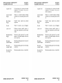
Added
Suplement 5
I (KFC 200 Automatic Flight
Control System without
Flight Director).
Revised sec. 4 (b) (1}.
Added Supplement 16
(Propeller Synchrophaser
Installation),
Added Supplement 17
(Century 21 Autopilot
Installation).
Added Supplement 18
{Century 41 Autopilot
Installation).
g
g
Ward Evans
21, 1981
April
REPORT:
VB-1110
y
OPERATING
PILOTS
Revision
Number and
Code
Revised
Pages
Rev. 2
(PR810817)
3-15
34
4-i
4-ii
4-4
4-5
4-9
4-10
4-12
4-15
4-16
4-16a
4-16b
4-17
4-18
4-19
4-26
4-27
4-32
4-33
REPORT:
vi
VB-1110
HANDBOOK
Description
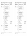
LOG OF REVISIONS
of Revision
Revised para. 3.3.
Revised para. 3.7.
Changed pg. nos.
Changed pg. nos.
Revised para. 4.5.
Revised para. 4.5.
Revised para. 4.5.
Revised para. 4.5.
Revised para, 4.5,
Moved para, 4.11 to pg. 4-16.
Relocated para. 4.11 from
pg. 4-15; moved info. to
pg. 4-16a.
New pg; relocated info.
from pg. 4-16 and 4-17,
New pg; relocated info. and
para. 4.13 from pg. 4-17;
added Note to para. 4.13.
Moved info. to pgs. 4-16a
and 4-16b; relocated info.
from pg, 4-18,
Moved info. to pg. 4-17;
relocated info. from
pg, 4-19.
Moved info, to pg. 4-18.
Revised para. 4.31; added
Note; moved para. 4.33 to
pg. 4-27,
Retocated para. 4.33 from
pg. 4-26.
Added Note; moved info. to
pg. 4-33.
Relocated info. from
pg. 4-32 moved info. to
pg. 4-34
(cont)
FAA Approval
Signature and
Date
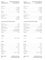
PILOTS
Revision
Number and
Code
Rev. 2
(PR810817)
(cont)
OPERATING
Revised
Pages
4-34
4-35
4-36
4-37
4-38
6-i
6-! I
6-12
6-32
6-33
6-34
6-35
6-40
6-46
HANDBOOK
Description
LOG OF REVISIONS
(cont)
FAA Approval
Signature and
Date
of Revision
Relocated info. from
pg. 4-33; moved para. 4,49
to pg. 4-35.
Relocated para. 4.49 from
pg. 4-34; moved para. 4.55
to pg. 4-36.
Reiocated para. 4.55 from
pg. 4-35; moved info. to
pg. 4-37.
Relocated info. from
pg. 4-36; moved para. 4.59
to pg. 4-38.
New pg; relocated
para
from pg. 4-37.
Changed pg. nos.
Revised fig, 6-9.
Revised fig. 6-i 1.
Relocated items 147 thru
15 i from pg, 6-33.
Moved items 147 thru 151
to pg. 6-32: added new item
154; relocated items 155
thru 159 from pg. 6-34.
Moved items 155 thru 159
to pg. 6-33; relocated item
173 from pg. 6-35.
Moved item 173 to pg. 6-34;
removed previous item 177;
added new items 177 and 178.
Revised item 223.
Added new items 264 and
item 266;
265; renumbered
moved items 271 and 273 to
pg. 6-.47.
REPORT: VB-1110
vi-a
PILOT'S
Mvision
Number and
Code
Rev. 2
(PR810817)
OPERATING
Revised
Pages
6-47
(cont)
6-48
6-49
6-50
6-62
7-14
7-15
7-20
7-21
9-46
9-49
9-50
9-51
9-53
9-105
Rev. 3
(PR820225)
I-4
3-i
J-fi
3-4
3-15
REPORT:
vi-b
VB-Ill0
HANDBOOK
Description
LOG OF REVISIONS
of Revision
Relocated items 271 and 273
from pg. 6-46: added new
item 272: moved items 28 I
and 283 to pg. 6-48.
Relocated items 28 1 and 283
from pg. 6-47: moved item
287 to pg, 6-49,
Relocated item 287 from
pg. 6-48: moved item 291
to pg. 6-50.
Relocated
item 29 l from
6-49.
pg.
Added new item 441.
Revised para. 7.15.
Revised fig. 7-11.
Added info.
Revised fig. 7-15.
Revised Supplement.
Section I.
Added Caution Note; moved
info. to pg. 9-50.
Relocated info. from
pg. 9-49.
Revised Supplement,
Section 3.
Revised Supplement.
Section 3.
Revised Supplement,
Section 4
Corrected para. L9.
Expanded checklist; moved
info. to pg. 3-ii.
Relocated info. from pg. 3-i.
Revised para. 3-3.
Revised para 3.7.
(cont)
FAA Approval
Signature and
Date
er
Ward Evans
Aug. 17 198 I
PILOT'S
on
Number and
Code
3
(PRS20225)
(cont)
OPERATING
HANDBOOK
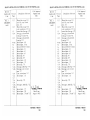
LOG OF REVISIONS
FAA
Revised
Pages
3-23
4-i
4-ii
4-18
4-30
4-37
5-3
5-14
5-20
5-22
5-23
5-26
5-28
5-29
5-30
5-31
Description
of Revision
(cont)
ApprovÃ
Signature and
Date
Amended para. 3.29.
Expanded checklist: moved
info. to pg. 4-ii.
Relocated info. from pg. 4-i.
Revised para. 4.17.
Corrected error.
Removed Note.
Corrected error.
Revised fig. 5-7 heading info.
Corrected error to fig. 5-19
info.
Revised fig, 5-23 heading.
Revised fig. 5-25.
Revised fig. 5-31 pg. base info.
Amended fig. 5-35 notation,
Added grid alignment number
to fig. 5-37.
Amended lettered info. to
fig. 5-39
Corrected error to fig. 5-41
example.
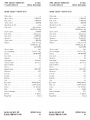
6- I
Revised para. 6. l.
6-6
6-9
6-10
6-! l
6-12
6-19
6-2 I
6-31
6-35
6-37
6-40
6-41
6-44
6-46
Revised fig. 6-5 info.
Corrected para. 6.7 (b).
Revised para. 6.7.
Corrected fig. 6-9.
Corrected fig. 6-11.
Revised para. 6.13,
Revised item i i data.
Revised item 135.
Revised item 177 data.
Revised item 193 data.
Revised item 223 b. data.
Revised item 227 a. data.
Revised item 255 data.
Revised and moved item 269
to pg. 6-47.
REPORT:
VB-1110
vi-c
PILOT'S
OPERATING
HANDBOOK
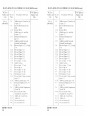
LOG OF REVISIONS
Revision
Number and
Code
Revised
Pages
Rev. 3
(PRS20225)
6-47
(cont)
6-48
6-49
Description
of Revision
6-51
6-52
6-54
6-56
6-68
6-69
7-3. 7-4
7-12
7-18
7-19
7-20
7-26
7-29
7-34
7-37
8-14
REPORT:
vi-d
VB-Il10
FAA Approval
Signature
and
Date
Relocated
item 269 from pg.
6-46: revised item 272 data:
moved item 277 and 279 to
pg. 6-48,
Relocated item 277 and 279
from pg. 6-47; moved item
285 to pg. 6-49.
Relocated item 285 from pg.
6-48; moved item 289 to pg.
6-50.
6-50
(cont)
Relocated item 289 from pg.
6-49; revised item 293 data;
moved item 295 and 297 to
pg. 6-51.
Relocated items 295 and 297
from pg. 6-50: tevised item
301 data.
Added new item 302.
Revised item 315: revised
item 319 data.
Revised item 385 (f) data.
Moved info to new pg 6-69.
New pg.: relocated info
from pg. 6-68; added
caution note.
Revised para. 7.5.
Revised para. 731
Revised voltage info. to para
7.17.
Revised fig. 7-13.
Revised para. 7.17.
Revised para. 7.23.
Corrected info listings 29.
46. 47.
Revised para. 7.27 info.
Amended
para 7.37,
Revised para. 8.23.
PILOT'S
OPERATING
HANDBOOK
Revised
Description
Revision
Number and
Code
Rev. 3
(PR820225)
(cont)
LOG OF REVISIONS
FAA Approval
Signature and
Date
of Revision
Pages
.
8-17
8-19
9-16
9-20
9-22
9-26
9-27
9-34
9-35
9-36
9-37
9-39
9-4 I
9-76
9-l10
9-115
9-120
9-123
9-125
thru
Revised para. 8.31 (b)
Corrected error.
Corrected error.
Added info. to listing.
Revised caution note:
corrected
pg. no. error.
Corrected error.
Revised section 4 (g)
Added info. to listing.
Revised section 2 (f)
Revised caution note;
. corrected
pg. no, error.
Revised section 3 (d) (2).
Corrected error.
Revised section 4 (4).
Corrected pg. no. error.
Revised note.
Revised note.
Corrected error.
Added heading to section 5.
New pgs.; added
supplement 19.
9-130
Res. 4
(PRS20409)
3-i.
3-ii
3-5
3-6
3-7
3-8
(cont)
ww½t
we
Ward Evans
Feb. 25, 1982
Changed pg. nos
Revised and added to
procedure; moved info.
to pg. 3-6.
Relocated info. from pg. 3-5;
moved info. to pg. 3-7.
Relocated info. from pg. 3-6;
moved info. to pg. 3-8.
Relocated info. from pg. 3-7;
moved info. to pg. 3-9.
REPORT:
VB-1110
vi-e
PILOT'S
OPERATING
Revision
Number and
Code
Revised
Pages
Rev, 4
3-9
of Revision
Description
3-10
3-1 I
3-16
3-17
3-18
3-19
3-20
3-21
5-17
6-20
6-29
7,5
7-6
from pg. 3-8:
pg. 3-10.
from pg. 3-9
pg. 3-11.
from pg. 3-10.
Revised and added to
para. 3.7
Added to para. 3.7; moved
info. to pg. 3-18.
Relocated
info- from pg. 3-17:
moved info. to pg. 3-19.
Relocated info, from pg. 3-18;
moved info. to pg, 3-20.
Relocated info, from pg. 3-19:
moved info. to pg. 3-21.
Relocated
info. from pg. 3-20,
Revised fig. 5-13.
Revised items I and 3.
Added item 129.
Revised para. 7.7.
Cont. rev. para. 7.7: moved
para 7.9 to pg. 7-6b.
:
relocated
para. 7.9
from pg. 7-6.
8-10
Revised
para.
8.17.
Title
Revised
Revised
Revised
Revised
Title
Page.
di
I-1
I-5
3-ii
3-9
3-20,
3-21
REPORT:
vi-f
FAA Approval
Signature and
Date
Relocated info.
info. to
Relocated info.
moved info. to
Relocated
info.
6b
Rev. 5
(PRS20809)
(cont)
moved
(PRS204()9)
(cont)
LOG OF REVISIONS
HANDBOOK
VB-1110
para.
para. I l.
para, 1.15.
Revised Table of Contents.
Revised procedure
Revised para. 3.23.
Ward Evans
April 9. 1982
PILOT S OPERATING
Number and
Code
Revised
Pages
Rev. 5
(PRS20809)
3-22
(cont)
3-23
I-5
3-24
3-25
4-l6a
5-3
6-i
6-l
6-2
6-5
6-7
6-1 I
6-15
7- I 8
7-l9
7-19a
7-19b
7-20
26.
7-27
7-28,
HANDBOOK
Description
LOG OF REVISIONS
of Revision
(cont)
FAA Approval
Signature
and
Date
Moved info to pg. 3-23
and 3-24, cont, revised
para, 3.23.
Moved info. to pg. 3-24.
cont revised para. 3.23, relocated info. from pg. 3-22.
info.
New page; relocated
from pg. 3-22 and 3-23,
New page; relocated info.
from pg. 3-23.
Revised para. 4.f l.
Revised para. 5.5 (a)
Revised Table of Contents.
Revised para. 6.\
Revised para. 6 3.
Revised para. 6 5.
Revised fig. 6-7.
Revised fig. 6-9.
Revised para 6.11Revised para. T IT
Revised fig. 7-13.
New page, added fig. 7-14.
New page. cont revised
para. 7.17.
Cont, revised para. 7 IT
Revised para. T23,
Revised fig. 7-2L
7-29
7-29a,
New pages. added
fig. 7-22.
94b
35
7-36
Ilevised para. T27.
Revised para. 7.29.
Revised para. 7.31 and T33.
Ward Evans
August 9, 1982
REPORT:
VB-1110
vi-g
PILOT'S
OPERATING
HANDBOOK
LOG OF REVISIONS
Revision
Number and
Code
FAA
Redsed
Pages
Rev. 6
(PRH30923)
i-4
1-8
|-10
2-4
2-l2
2-13
5-9
5-24
5-25
5-26
5-27
5 28
\6
0
8-2
8 3
84
8 l9
8-20
9-i
9-ii
9-10
9-!i
9-l]
9-28
9-42
REPORT:
vi-h
VB-Ill0
Description
of Redsion
Added items (c) (3) and (c) (4)
to para. l.5
Revised barometric
pressure
(mb).
Deleted MEA.
Added items (i) c. and (i) d.
to para 2.7.
Relocated
fuel placard to
pg 2-l3,
Added pg. (added new and
relocated
fuel placards)
Revised Figures 5-27. 5-29 and
5-31.
Revised Figure 5-27.
Revised Figure 5-29.
Figure 5-3l.
Revised Figure 5-33,
Revised Figure 5-35
Revised para.
.l5 info.
Added Caution.
Redsed parm 7.25 into
Revised pg. no.
Reiised para. 8.3 info.
Re sed para. 8.5 info.
Deleted para. 8.5 info.
Revised item R.3l (gy relocated
para. 8.33
Added pg. (added para 8.33}.
No 19
Relocated Supplement
to pg. 9-u.
Added pg. (added Supplements
19 and 20).
Revised Section I info
relocated
info. to pg. 9-1 E
Resised
Added and relocated
Added info
Redsed item (hi (1)
Retised item (h) (!).
info.
(cont)
Approval
Signature and
Date
PILOT'S
HANDBOOK
OPERATING
LOG OF REVISIONS
FAA Approval
Signature and
Date
Revision
Number and
Code
Revised
Pages
R
6
(PRS30923)
(cont)
9-82
9-131
thru
9- I34
Rev. 7
(PRS402l0)
4-5
4-6
4-7
4-8
4-9
4-10
4-16b
4-25
4-26
4-28
7-i
7 11
7-12
8-6
8-7
84
9-i
9-ii
9-9
5
thru
9-154
!
Description
(cont)
of Revision
Deleted Note.
Supplement No. 20
(Edo-Avionics Command
Elect ric Trim System)
Ward Evans
Sept 23, 1983
Added Warning; moved info.
to pg. 4-á
Relocated info, from pg, 4-5:
moved info. to pg. 4-7.
Relocated info. from pg. 4-6.
Revised procedure.
Revised procedure.
Revised procedure.
Revised para. 4.13.
Revised para. 4.29.
Revised para. +31.
Revised para 4.33.
Revised Table of Contents
Relocated info from pg 7-12
Moved info to pg 7-I I: revised
para. 7. I l.
Revised para 8.9; moved info
to pg. 8-7.
Relocated info. from pg. 8-6:
moved info. to pg. 8-8.
Relocated info. from pg- 8-7
Revised Table of Contents
Added Supplement 2I.
Revised title.
.RAL isedpla
e ; added Supplement 21, Century 31 Autopilot
Installation.
Ward Evans
Feb. 10. 1984
Added
REPORT:
VB-Ill0
vi-i
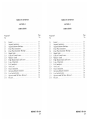
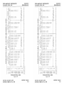
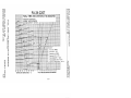
TABLE OF CONTENTS
SECTION 1
GENERAL
SECTION 2
LIMITATIONS
SECTION
3
EMERGENCY
PROCEDURES
PROCEDURES
SECTION 4
NORMAL
SECTION 5
PERFORMANCE
SECTION 6
WEIGHT AND BALANCE
SECTION 7
DESCRIPTION AND OPERATION OF
THE AIRPLANE AND ITS SYSTEMS
SECTION 8
AIRPLANE HANDLING, SERVICING
SECTION 9
SUPPLEMENTS
SECTION 10
SAFETY TIPS
AND MAINTENANCE
REPORT:
VB-1110
vii
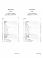
TABLE OF CONTENTS
SECTION
I
GENERAL
Page
Paragraph
No.
No.
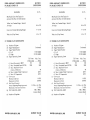
Ll
Introduction
L3
Engine
Propeller
Fuel
Oil............-Maximum Weights
Standard Airplane Weights
Baggage Space
Specific Loadings..............
Symbols, Abbreviations and Terminology.............
L5
1
1.9
1 ll
1.13
1 15
Ll"
l.\9
...........
..
............
............
.
.
.
.........
...........
.
.
.........
.
..
..............
.........
.
.
..............
.
...........
.
..-..........
..............
..........
.........
.............
......
.
.........
REPORT:
1-1
1-3
|-3
1-4
I-4
1-5
1-5
1-5
1-5
1-6
VB-ll10
1-i
PIPER AIRCRAFT CORPORATION
PA-34-220T, SENECA III
SECTION
SECTION
I
GENERAL
1
GENERAL
Ll INTRODUCTION
This Pilot's Operating Handbook is designed for maximum utilization
guide for the pilot. It includes the material required to be
as an operating
supplemental
data
furnished to the pilot by FAR 23. It also contains
supphed by the airplane manufacturer.
This handbook is not designed as a substitute for adequate and competent flight instruction, knowledge of current airworthiness directives and
applicable
federal air regulations or advisory circulars. It is not intended to
be a guide for basic flight instruction or a training manual and should not be
used for operational
purposes unless kept in a current status.
that the airplane is in an airworthy condition is the responsi,
Assurance
bility of the owner. The pilot in command is responsible for determining that
the airplane
is safe for flight. The pilot is also responsible
for remaining
within
limitations as outlined
by instrument markings,
the operating
placards. and this handbook.
of this handbook
Ahhough
the arrangement
is intended to increase its
m-fhght capabilities,
it should not be used solely as an occasional operating
reference.
The pilot should study the entire handbook to become familiar
with the limitations,
performance, procedures
and operational
handling
characteristics
of the airplane before flight,
The handbook has been divided into numbered (arabic) sections, each
provided with a "finger-tip" tab divider for quick reference. The limilations
and emergency procedures have been placed ahead of the normal
procedures,
performance and other sections to provide easier access to
that may be required in flight. The "Emergency Procedures"
míormation
Section has been furnished with a red tab divider to present an instant
of the handbook have
reference to the section. Provisions for expansion
been made by the deliberate omission of certain paragraph numbers, figure
numbers.
item numbers and pages noted as being intentionally left blank.
8. 1981
AUGUST 9, 1982
ISSUED: JANUARY
REVISED:
REPORT: VB-1110
1-1
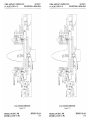
PIPER AIRCRAFT CORPORATION
PA-34-220T, SENECA IH
SECTION 1
GENERAL
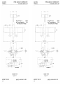
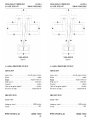
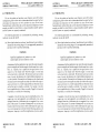
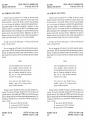
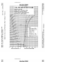
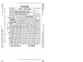
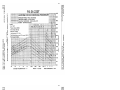
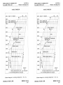
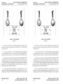
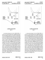
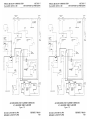
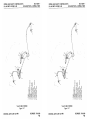
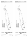
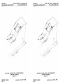
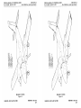
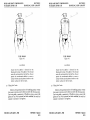
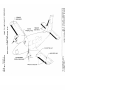
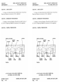
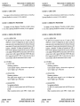
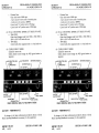
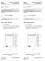
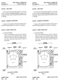
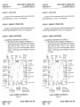
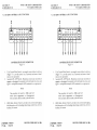
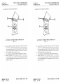
T10.28"
Wing Area (sq. ft.)
208 J
Min. Turning Radius (ft.)
33.2
{frompivot point to wingtip)
6 4 90 -
1914T
8 10.87"
1T 5.4"
414
METER
INEDRAL
4 43
1 84
-
28744
11
CENTER LME1
IN
SPAltSTA 108 825
STATIC
GRTIllNO
LINE
THREE VIEW
Figure I I
REPORT:
1-2
VB-Illo
ISSUED: JANUARY
8, 1981
SECTION 1
GENERAL
PIPER AIRCRAFT CORPORATION
PA-34-220T, SENECA III
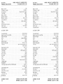
l.3 ENGINE
2
(a) Number of Engines
(b) Engine Manufacturer
(c) Engine Model Number
(1) Left
(2) Right
(d)
(e)
(f)
(g)
(h)
(i)
(j)
Rated Horsepower
Rated Speed (rpm)
Bore
(inches)
Stroke (inches)
Displacement (cubic inches)
Compression Ratio
Engine Type
Continental
TSIO-360K B
LTSlO-360KB
T.O. Power
5 Min. Limit
220 BHP
2800
Max. Cont.
Power
200 BHP
2600
4.438
3.875
360
7.5:1
Six Cylinder, Direct Drive,
Horizontally Opposed,
Air Cooled
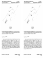
1.5 PROPELLER
STANDARD
ta)
(b)
(c)
of Propellers
Propeller Manufacturer
Propeller Hub & Blade Models*
(1) Left
2
Hartzell
Number
(2) Right
BHC-C2YF-2CKUF|
FC8459-8R
BHC-C2YF-2CLKUF|
FJC8459-8R
Number of Blades
(e) Propeller Diameter (in.)
(1) Maximum
(2) Minimum
(f) Propeller Type
2
(d)
*The propellers
ISSUED:
76
75
Constant Speed.
Hydraulically Activated.
Full Feathering
have the same designation when deicing boots are installed.
JANUARY
8, 1981
REPORT:
VB-1110
I-3
PIPER AIRCRAFT CORPORATION
PA-34-220T, SENECA III
SECTION I
GENERAL
OPTIONAT
(a) Number of Propellers
(b) Propeller Manufacturer
(c) Propeller Hub & Blade Models*
(1) Left
2
McCauley
3AF32CSOS
82NFA-6
3AF32C509
LR2NFA-6
(2) Right
or
32AF32C508-( ) ( )-82NFA-6
32AF32C509-( ) ( )-LS2NFA-6
(3) I eft
(4) Right
(d) Number of Blades
(el Propeller Diameter (in.)
(1) Maximum
(2) Minimum
(f) Propeller Type
3
76
75
Constant Speed,
Hydraulically Activated.
Full Feathering
L7 FUEL
(a) Fuel Capacity (LLS. gal ) (total)
(1) Without optional tanks
(2) With optional tanks
(b) l½able Fuel (LS gat) (total)
Without
(!)
optional
(2) With optional
98
128
93
123
tanks
tanks
(c) Fuel
(I)
Minimum Grade
!00 Green or 100LL
Blue Aviation Grade
Refer to latest revision
of Continental Senice
Bulleún "Fuel and Oil
(2) Alternate FueW
Grades."
L9 OIL
(a) Oil Capacits (I
(b) Oil Specification
S. ytsj (per
engine)
8
Refer
of
to latest revision
Continental
Bulletin
"Fuel
Service
and O
Grades
*The propellers have the
REPORT:
04
VB4110
same
designanon
when deicing
"
boots are installed.
ISSUED: JANUARY 8. 1981
REVlSED: SEPTEMBER
23, 1983
CORPORATION
PIPER AIRCRAFT
PA-34-220T, SENECA III
SECTION I
GENERAL
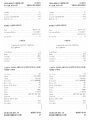
tc) Oil Viscosity
Aviation
S.A.E.
No.
30
(1) Below 40°F
\ 100
50
(2) Above 40°F
When operating
temperatures overlap indicated ranges, use the
lighter grade of oil. Multi-viscosity oils meeting Teledyne Continental Motors' Specification MHS-24A are approved.
Grade
1065
1.11 MAXIMUM WEIGHTS
(a) Max. Ramp Weight (lbs.)
Max. Takeoff Weight (Ibs.)
Max. Landing Weight (lbs.)
Max. Zero Fuel Weight (Ibs.)
le)
Max. Weights in Baggage
Compartment.(Ibs.)
(I) Forward
(2) Aft
(b)
(c)
(d)
1.13 STANDARD
AIRPLANE
4773
4750
4513
-
Std.
4470
100
100
WEIGHTS
Reíer to Figure 6-5 for the Standard
Load.
Empty
Weight and the Useful
L15 BAGGAGE SPACE
Maximum Baggage (Ibs.)
(b) Baggage Space (cu. ft.)
(c)
Baggage Door Size (in.)
ta)
1.17 SPECIFIC
(al
(b)
FORWARD
100
15.3
AFT
100
17.3
24 x 21
LOADINGS
Loading (lbs. per sq. ft.)
Power Loading (lbs. per hp)
22.8
10.8
Wing
ISSCED: JANUARY 8, 1981
REVlSED: AUGUST 9, 1982
REPORT:
VB-Il10
1-5
SECTION 1
GENERAL
L19 SYMBOLS,
PIPER AIRCRAFT CORPORATION
PA-34-220T, SENECA III
ABBREVIATIONS
AND TERMINOLOGY
abbreviations
and
The following definitions
are of symbols,
the handbook and those which may be of
terminology used throughout
significance
added operational
to the pilot.
(a) General Airspeed Terminology
and Symbols
CAS
Calibrated Airspeed means the indicated
speed of an aircraft. corrected for position
and instrument error. Calibrated airspeed
is equal to true airspeed
in standard
atmosphere
at sea leveL
KCAS
Calibrated Airspeed expressed
GS
Ground Speed is the speed
to the ground.
in "Knots."
of an airplane
relative
lAS
Indicated Airspeed
is the speed of an
aircraft as shown on the airspeed indicator
when corrected for instrument error. lAS
values published
in this handbook assume
zero
KIAS
M
mstrument
indicated
error.
Airspeed expressed
Mach Number is the
to the speed
ratio
in "Knots.
of true airspeed
of sound.
TAS
True Airspeed is the airspeed of an airplane
relative to undisturbed
air which is the
CAS corrected for altitude.
temperature
and compressibility.
VA
Maneuvering
Speed is the maximumspeed
application
of full available
at which
aerodynamic
control will not overstress the
airplane,
VFE
Tvlaximum Flap Extended Speed is the
highest speed permissible with wing flaps
in a prescribed extended position.
REPORT:
E6
VB-Il10
ISSUED:
JANUARY
8, 1981
PIPER AIRCRAFT CORPORATION
PA-3&220T, SENECA III
SECTIØN
I
GENERAL
Maximum Landing Gear Extended Speed
is the maximum speed at which an aircraft
can be safely flown with the landing gear
Vu
extended.
VLo
Maximum LandingGearOperating
Speed
is the maximum speed at which the landing
or retracted.
gear can be safely extended
VMcA
Air Minimum Control Speed is the miniflight speed at which the airplane is
directionally controllable
as determined in
accordance with Federal Aviation ReguAirplane
lations.
certification
conditions
include one engine becoming inoperative
and windmilling:
not more than a 5° bank
towards
the operative
engine; takeoff
power on operative engine; landing gear
up; flaps in takeoff position; and most
rearward
C.G.
mum
Never Exceed Speed or Mach Number is
the speed limit that may not be exceeded at
i MNE
VNI
any time.
VNo
Maximum
Structural Cruising Speed is the
speed that should not be exceeded except
in smooth air and then only with caution.
Vs
Stalling Speed or the minimum
flight speed at which the airplane
steady
is con-
trollable,
Vso
steady
Stauing Speed or the minimum
is
flight speed at which the airplane
controllable
in the landing configuration.
VssE
One Engine inoperative Speed
speed selected by the manufacturer for intentionally rendering one
engine
inoperative
in flight for pilot
trammg.
Intentional
is a minimum
ISSUED:
JANUARY
8, 1981
REPORT:
VB-1110
1-7
PIPER AIRCRAFT CORPORATION
PA-34-220T, SENECA III
SECTION I
GENERAL
Best Angle-of-Climb Speed is the airspeed
which delivers the greatest gam of altitude
in the shortest possible horirontal distance.
Vs
Best Rate-of-Climb Speed is the airspeed
delivers the greatest gain in altitude
in the shortest possible time
Vs
which
(h) Meteorological
Terminology
in
Standard
Atmosphere
air is a dry perfect gas: The
at sea level is 15° Celsius (59°
Fahrenheit): The pressure at sea level is
29.92 inches Hg(10\3.2 mb);Thetemperature gradient from sea level to the altitude
the temperature
is -56.5°C
at which
(-69.7°F) is -0.00198°C (-0.003566°F) per
foot and 7ero above that altitude.
international
ISA
which:
The
temperature
OAT
Air Temperature
is the free air
obtained
either from
temperature
inflight temperature
indications or ground
meteorological
adiusted
for ire
sources,
effects,
strument
error and compressibility
Outside
static
Indicated
Pressure Altitude
Pressure Altitude
The
number
altimeter
actuallt
read
from
an
subscale
barometric
has been set to 29 92 inches of mercurv
(1013.2 mllihars).
when
Altitude
the
measured
from standard
sea-level
pressure (29.92 in. H g) by a pressure or
barometric altimeter.
It is the indicated
pressure altitude corrected for position and
In this
instrument
handbook,
error.
altimeter
instrument errors are assumed
to be vero.
Station Pressure
REPORT:
pg
VB-1110
atmospheric
Actual
elevation
pressure
ISSUED: JANUARY
REVISED:
SEPTEMBER
at
field
8. 1981
23, 1983
PIPER
AIRCRAFT
SENECA
PA-3&220T,
SECTION I
GENERAL
CORPORATION
III
recorded
as variables
the
charts
of
this
handbook
are to be
on
understood
or tailwind
as the headwind
winds.
of the reported
components
The wind velocities
Wind
(c) Power Terminology
Takeoff Power
Maximum power permissible for takeoff.
Maximum ConPower
during flight.
tinuous
Maximum
Climb
Maximum
power
permissible
during
power
permissible
during
climb.
Power
Maximum
Power
Maximumpowerpermissiblecontinuously
Cruise
Maximum
cruise,
(d) Engine Instruments
EGT Gauge
(el
Gauge
Airplane Performance
and Flight Planning
Climb Gradient
The demonstrated ratio of the change in
height during a portion of a climb, to the
horizontal distance traversed in the same
time intervaL
Demonstrated
The demonstrated crosswind velocity isthe
of the crosswind
for
component
of the airplane
which adequate
control
during takeoff and landing was actually
Crosswind
Velocity
(DE MO
X-WlND)
Accelerate-Stop
Distance
ISSUED:
Exhaust Gas Temperature
JANUARY 8, 1981
Terminology
velocity
demonstrated
during
certification
tests.
The distance required
to accelerate an airspecified
speed
and. assuming
plane to a
failure of an engine at the instant that speed
is attained, to bring the airplane to a stop.
REPORT: VB-IIIO
1-9
PIPER AIRCRAFT
SECTION 1
GENERAL
CORPORATION
PA-34-220T, SENECA III
Route Segment
A part of a route Each end of that part is
identified by: (1) a geographical location:
or (2) a point at which a definite radio fix
can he established.
and
(f) Weight
Bahmcc Terminology
Reference Datum
An imaginary vertical
distances
balance purposes.
horizontal
plane from which all
for
are measured
Station
fuselage
A location along the airplane
usually given in terms of distance in inches
from the reference datum.
Arm
The horizontal distance from the reference
datum to the center of gravity (C.G.) of an
item.
Moment
Center
(C G.)
of Gravity
The product of the weight ofan item multiplied by its arm- (Moment divided by a
constant is used to simplify balance calculations bv reducing the number of digits )
The point
balance if
at
which
an
airplane
wou!d
Its distance from the
reference datum is found by dividing the
total moment by the total weight of the
airplane.
suspended.
C.G. Arm
by adding the airplane's
The arm obtained
individual moments and dividing the sum
by the total weight.
C G. 1,imits
center of gravity locations
within which the airplane must be operated
at a given weight,
t
REPORT:
1-10
able Fuel
VB-ll10
The extreme
Fuel available
for flight planning
ISSUED: JANUARY 8, 1981
REVISED: SEPTEMBER 23, 1983
SECTION I
GENERAL
CORPORATION
PIPER AIRCRAFT
PA-34-220T, SENECA III
Unusable Fuel
Fuel remaining after a runout test has been
with governcompleted
in accordance
.
mental regulations.
Standard
Weight of a standard
airplane including
unusable fuel, full operating
fluids and full
oil.
Empty
Weight
Basic Empty
Standard
Weight
e4uipment.
Payload
Weight
empty
of occupants,
Difference
Eseful Load
between
Maximum
Ramp
Maximum
Takeoff Weight
Maximum
Landing Weight
Maximum Zero
Fuel Weight
ISSUED: JANUARY
8, 1981
and baggage.
cargo
weight,
or
and basic empty
takeoff
ramp weight if applicable,
weight.
Weight
plus optional
weight
weight approved
for ground
includes weight of start, taxi
(It
maneuver.
and run up fuel.)
Maximum
Maximum weight approved
the takeoff
for the start of
run.
Maximum weight approved
touchdown.
for the landing
Maximum
of usable fuel.
weight exclusive
REPORT:
VB-1110
1-11
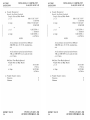
TABLE OF CONTENTS
SECTION
2
LIMITATIONS
Page
No.
Paragraph
No.
2.1
23
2.5
2.7
2.9
2.11
2.13
2.15
2.17
2.19
2.2 I
2,23
2.25
227
229
2 31
233
General
.......
.
..........,
Airspeed Limitations
Airspeed Indicator Markings.........
Power Plant Limitations..........
.........
..
.
.
.......
.
...
Power Plant instrument Markings
Limits.............
Center of Gravity Limits..............
Maneuver Limits
Flight Maneuvering Load Factors
Types of Operation
Fuel Limitations
Noise Level
Heater Limitations..........
Operating Altitude Limitations
Gyro Suction limits
Operation with Aft Doors Removed
Weight
.........
.
.
..
...................
.........
.
............
.......
.
........
..
........
.
.
...................
.....
..........
-
,
.
-
-
-
-
-
.
.
.
.
.
........
...........
.......
...........
.
.........
.............
Placards...--......
.......
.........
.
.
.......
.......
.
.
.
.
.
2-1
2-1
2-2
2-3
2-5
2-6
2-6
2.7
2-7
2-7
2-7
2-8
2-8
2-8
2-8
2-8
2-9
REPORT: VB-1110
2-i
SECTION 2
LIMITATIONS
PIPER AIRCRAFT CORPORATION
PA-34-220T, SENECA III
SECTION
2
LIMITATIONS
2.1 GENERAL
limitations,
section
provides the "FAA Approved" operating
placards
coding
and
basic
color
necessary for the
instrument markings,
and
of
airplane
its
the
systems.
operation
This
airplane in
category
must be operated
as a normal
This airplane
limitations stated in the form of placards
with the operating
compliance
and markings and those given in this section and handbook.
Limitations
which
require
with
associated
handbook
those optional systems and equipment
can be found in Section 9
supplements
(Supplements).
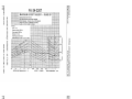
2.3 AIRSPEED
LIMITATIONS
KIAS
SPEED
Design Maneuvering
make full or abrupt
Speed
control
(VA)
-
KCAS
Do not
movements
above this speed.
4750 lbs.
140
l14
3205 lbs.
140
115
CAUTION
Maneuvering
as the effects
speed decreases at lighter weight
of aerodynamic
forces become
may
more pronounced. Linear interpolation
be used for intermediate
gross weights.
Maneuvering speed should not be exceeded
while operating
in rough air.
ISSUED:
JANUARY 8, 1981
REPORT: VB-Il10
2-1
PIPER
2
LIMITATIONS
SECTION
AIRCRAFT CORPORATION
PA-34-220T, SENECA III
KIAS
SPEED
Never Exceed Speed (VNF)
this speed in any operation.
-
KCAS
Do not exceed
205
203
166
165
Il5
113
130
I30
Maximum Landing Gear Extending
Speed (VLo)
Do not extend landing
gear above this speed.
130
130
Maximum Landing Gear Retracting
(VLo)
Do not retract landing
this speed.
above
gear
108
109
66
65
92
91
Maximum Structural Cruising Speed
Do not exceed this speed except
in smooth air and then only with caution.
(VNo)
-
Maximum Flaps Extended Speed (VEE)
Do not exceed this speed with the flaps
-
extended.
Maximum
Gear Extended Speed (VLF)
this speed with landing
exceed
Do not
extended.
gear
-
-
Speed
-
Air Minimum Control Speed (VMcA)
Lowest airspeed at which airplane is controllable with one engine operating
at
takeoff power and no flaps.
One Engine Inoperative
Climb Speed.
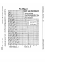
2.5 AIRSPEED
Best Rate of
(VvsE)
INDICATOR
MARKINGS
KlAS
MARKlNG
Red Radial Line (Never Exceed)
205
Red Radial Line (One Engine Inoperative
Air Minimum Control Speed)
REPORT:
2-2
VB-llIO
ISSUED:
66
JANUARY
8, 1981
SECTION 2
LIMITATIONS
PIPER AIRCRAFT CORPORATION
III
PA-34-220T, SENECA
KIAS
MARKING
Blue Radial Line (One Engine inBest Rate of Climb (Speed)
92
operative
Yellow Arc (Caution
Air Only)
Range
-
Green Arc (Normal Operating
Smooth
166 to 205
67 to 166
Range)
64 to I15
White Arc (Flap Down)
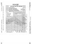
2.7 POWER PLANT
LIMITATIONS
2
(a) Number of Engines
(b) Engine Manufacturer
(c) Engine Model Number
(1) Left
(2)
TSIO-360KB
LTSIO-360K B
Right
(d) Engine Operating Limits
Rated Horsepower (BHP)
Rotational Speed (RPM)
Max.
(2)
(3) Max. Manifold Pressure
(Inches of Mercury)
(4) Max. Cylinder Head Temperature
(5) Max. Oil Temperature
(e) Oil Pressure
Minimum (red line)
Maximum (red line)
(f) Fuel Flow (Pressure)
Normal Operating Range (green arc)
Maximum at Sea Level (red line)
(g) Fuel Grade (min. grade)
(I)
(h) Number
ISSUED:
Continental
of Propellers
JANUARY 8, 1981
T.O. Power
5 Min. Limit
220
Max. Cont.
Power
2800
200
2600
40
460°F
240°F
10 PSI
100 PSI
3.5 PSI to 18.1 PSI
21 PSI
100 or 100LL
Aviation Grade
2
REPORT:
VB-1110
2-3
PIPER AIRCRAFT CORPORATION
PA-34-220T, SENECA III
SECTlON 2
LIMlTATIONS
(i)
Propeller Manufacturer
Hurtiell (Two Blade) (Standard)
Propeller Hub and Blade Models
a. I.cft
b. Right
BHC-C2YF-2CKUF
FCR459-8R
BHC-C2YF-2CLKUF
FJCB459-8R
or
c. l.eft
32AF32C508-(
)
( )-82NFA-6
32AF32C509-( P
( )-LS2NFA-6
d. Right
NOTES
Avoid continuous
operation
2200 RPM above
32 lN
between 2000 and
HG. manifold pres-
sure.
ground operation between
2100 RPM in cross and tail winds
over 10 knots.
continuous
Avoid
1700
and
McCauley (Three Blade) (Optional)
Propeller Hub and Blade Models
a. Left
b. Right
3AF32C508
82NFA-6
3AF32C509
LR2NFA-6
(i)
Propeller Diameter (inches)
Maximum
Minimum
REPORT:
2-4
VB-1110
76
75
ISSUED: JANUARY 8, 1981
REVISED: SEPTEMBER 23. 1983
SECTION 2
LIMITATIONS
CORPORATION
PIPER AIRCRAFT
PA-34.220T, SENECA III
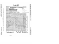
2.9 POWER
PLANT
INSTRUMENT
(a) Tachometer
Green Arc (Normal Operating
5 Min.)
Yellow Arc (Takeoff
Red Line (Maximum)
(b) Fuel Flow (Pressure)
Green Arc (Normal Operating
5 Min.)
Yellow Arc (Takeoff
Red Line (Max. at Sea Level)
(c) Cylinder Head Temperature
Green Arc (Normal Range)
Red Line (Maximum)
(d) Oil Temperature
Green Arc (Normal Operating
Red Line (Maximum)
(e) Oil Pressure
Green Arc (Normal Operating
Ground
Yellow Arc (Caution
Operation Only)
Red Line (Minimum)
Red Line (Maximum)
(f) Manifold Pressure
Green Arc (Normal Operating
Red Line (Maximum)
(g) Exhaust Gas Temperature
Red Line
Green Arc
Yellow Arc (65% to 75%
Leaning Limit)
MARKINGS
Range)
-
Range)
-
8, 1981
3.5 PSl to 18.1 PSI
18.1 PSI to 21.0 PSI
21.0 PSI
240°F to 460°F
460°F
Range)
100°F to 240°F
240°F
Range)
30 PSI to 80 PSI
10 PSI to 30 PSI and
-
ISSUED: JANUARY
500 RPM to 2600 RPM
2600 RPM to 2800 RPM
2800 RPM
80 PSI to 100 PSI
10 PSI
100 PSI
Range)
10 IN. to 40 IN. HG,
40 IN. HG
1650°F
1200°F to 1525°F
1525°F to 1650°F
REPORT:
VB-1110
2-5
PIPER
SECTION 2
LIMITATIONS
2.11 WEIGHT
AIRCRAFT CORPORATION
PA-34-220T, SENECA III
LIMITS
(a) Max. Ramp Weight
(b) Max Takeoff Weight
(c) Max. Landing Weight
(d) Max. Weights in Baggage Compartments
Forward
4773 LBS.
4750 LBS.
4513 LBS.
100 LBS.
100 LBS.
Aft
(e) Max. Zero Fuel Weight Standard
(Refer to Section 6, Weight and
Balance)
-
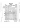
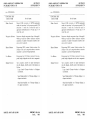
2.13 CENTER
OF GRAVITY
Weight
Pounds
4470 LBS.
LIMITS
Forward Limit
Inches Aft of Datum
Rearward Limit
Inches Aft of Datum
82.0
86.7
90.6
94.6
94.6
3400
4250
4750
94.6
NOTES
Straight
line variation
between points given.
The datum used is 78.4 inches ahead of the
wing leading edge at the inboard edge of the
fuel tank.
It is the
the
properly
Balance)
and
REPORT:
2-6
VB-Ill0
responsibility
of the airplane owner
pilot to ensure
that the airplane
is
loaded. See Section 6 (Weight and
for proper
loading instructions.
ISSUED: JANUARY
8, 1981
PIPER AIRCRAFT CORPORATION
PA-34-220T, SENECA III
2.15 MANEIR
ER LIMITS
All intentional acrobatic
Avoid abrupt maneuvers.
2.17 FLIGHT
SECTION 2
LIMITATIONS
maneuvers
MANEUVERING
(including
spins)
are prohibited.
LOAD FACTORS
(a) Positive Load Factor (Maximum)
(1) Flaps Up
(2) Flaps Down
(b) Negative Load Factor (Maximum)
3.8 G
2.0 G
No inverted
approved.
maneuvers
2,19 TYPES OF OPERATION
The airplane is approved for the following operations
with FAR 91 or FAR 135.
in accordance
when equipped
(a) Day LF.R.
(b)
(c)
(d)
(e)
Night L F.R.
Day LF.R.
Night I.F.R.
Icing conditions
when equipped per Ice Protection
lation Supplement (refer to Section 9).
System Instal-
2.21 FUEL LIMITATIONS
(a) Standard Fuel Tanks
98 U.S.
(1) Total Capacity
5 U.S.
(2) Unusable Fuel
The unusable fuel for this airplane has been determined as
gallons in each wing in critical flight attitudes.
93 U.S.
(3) Usable Fuel
(b) Optional Fuel Tanks
128 U.S.
(1) Total Capacity
5 U.S.
(2) Unusable Fuel
123 U.S.
(3) Usable Fuel
ISSUED: JANUARY
8, 1981
REPORT:
GALS.
GALS.
2.5 U.S.
GALS.
GALS.
GALS.
GALS.
VB-1110
2-7
AIRCRAFT CORPORATION
PA-34-220T, SENECA III
PIPER
SECTION 2
LIMITATIONS
2.23 NOISE LEVEL
The corrected noise level of this aircraft is 7 I.4d B(A) with the two blade
propeller and 74.2d B(A) with the three blade propeller.
No determination has been made by the Federal Aviation Administration that the noise levels of this airplane are or should be acceptable or
unacceptable
for operation at, into, or out of, any airport.
the noise level stated above has
The above statement notwithstanding,
by the Federal Aviation Administration in
been verified by and approved
with
noise level test flights conducted
in accordance
FAR 36. Noise
Airworthiness
Certification.
This aircraft
Aircraft
and
Type
Standards
applicable
with all FAR 36 noise standards
model is in compliance
to this
-
type.
2.25 HEATER
LIMITATIONS
Operation of the combustion
2.27 OPERATING
ALTITUDE
heater above 25.000 feet is not approved.
LIMITATIONS
Flight up to and including
Flight above 25,000 feet is not approved.
with FAR
25,0û0 feet is approved if equipped with oxygen in accordance
with FAR 91 or FAR 135.
23.1441 and avionics in accordance
2.29 GYRO SUCTION
LIMITS
limits for the suction system are 4.8 to 5.1 inches
The operating
as indicated by the gyro suction
for all operations
gauge.
of
mercury
2.31 OPERATION
WITH AFT DOORS
REMOVED
The maximum speed with the aft doors removed is 129 KIAS and the
speed is 67 KIAS. Door off operation
single engine control
minimum
is
conditions
non-icing
only.
approved
for VFR
REPORT:
2-8
VB-1110
ISSUED:
JANUARY
8, 1981
PIPER AIRCRAFT CORPORATION
PA-34-220T, SENECA III
SECTION
2
LIMITATIONS
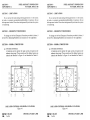
2.33 PLACARDS
In full
view
of the pilot:
THIS AIRPI ANE MUST BE OPERATED ASA NOR
IN COMPLIANCE
AIRPLANE
MAL CATEGORY
LIMlTATIONS
STATED
WlTH THE OPERAT]NG
MARKlNGS. AND
IN THE FORM OF PLACARDS,
(lNMANEUVERS
NO ACROBATIC
MANUALS.
CLUD1NG SPINS) APPROVED.
APPROVED
THIS AIRCRAFT
AND
ICING
NIGHT
DAY,
IN ACCORDANCE
EQUIPPED
FAR 135.
FOR
V.F.R,
l.F.R.,
WHEN
FLIGHT
WETH FAR 9! OR
In full view of the pilot:
TAKEOFF WEIGH T 4750 POUNDS
LANDING WEIGHT 4513 POUNDS
ALL WEIGHT IN EXCESS OF4470 POUNDS MUST
MAXIMUM
MAXIMUM
CONSISTOFFUEl..-(EXCEPTlNCASESSPECIFIED
6 OF P.O.H.).
BY SECTION
SlNGl E ENGINE CONTROL
MINiMUM
panel in full
On instrument
view
SPEED
66 KIAS
of the pilot:
VA
140 AT 4750 LBS.
(SEE A.F.M.)
VI.o
130 DN, 108 UP
VI.E 130 MAX.
DEMO X-WIND 17 KTS
Near emergency
gear release:
EMERGENCY GEAR EXTENSION
PULL TO RELEASE. SEE A.F.M.
BEFORE RE-ENGAGEMENT
ISSUED: JANUARY 8, 1981
REPORT:
VB-1110
2-9
PIPER
SECTION 2
LIMITATIONS
AIRCRAFT CORPORATION
PA-34-220T, SENECA III
switch:
Near gear selector
GEAR UP
DOWN
108 KIAS MAX.
130 KIAS MAX
Adjacent to upper door latch (front and rear doors)
ENGAGE
In full
view
LATCH BEFORE
FLIGHT
of pilot:
TURN OFF STROBE LlGHTS WHEN
WARNING
OR
TAXIING IN VICINITY OF OTHER AlRCRAFT
CLOUD, FOG OR
DURING FLlGHT THROUGH
HAZE.
-
On the inside of forward baggage compartment
door:
100
MAXlMUM BAGGAGE THlS COMPARTMENT
SECTlON OF THE
LBS. SEE THE LIMITATIONS
AIRPLANE FLIGHT MANUAL
On aft baggage closeout:
MAXIMUM
BAGGAGE THIS COMPARTMENT
LBS. NO HEAVY OBJECTS ON HAT SHELF.
In full view
100
of pilot:
SINGLE ENGINE STALLS NOT RECOMMENDED.
CAN CAUSE 400 FT. LOSS OF ALTITUDE AND 15°
PITCH ANGLE.
REPORT:
2-10
VB-1110
ISSUED: JANUARY
8, 1981
SECTION
PIPER AIRCRAFT CORPORATION
III
PA-34-220T, SENECA
On sun
2
LIMITATIONS
visor.
CHECK
TAKEOFF
LANDING
LIST
CHECK LIST
Backs Erect
Easten Belts Harness
Fuel Selectors On
Cowl Flaps Set
Mixtures
Rich
Aux. Fuel Pumps Off
Propellers Set
Gear Down
Flap Set (White Arc)
Air Conditioner Off
Seat
On
Fuel Selectors
Aux. Fuel Pumps Off
Alernators
On
Engine Gages Checked
Mixtures Set
Propellers Set
Alt. Air Off
Cow) FWps Open
Seat Backs Erect
Flaps Set
Trim Set (Stab. & Rudder)
Fasten Belts Harness
Controls Free Full Travel
Cond. Off
Doors Latched/Air
-
-
The "Air Conditioner Off" item in the above takeoff
aircraft only.
for air conditioned
list is mandatorv
On storm
and landing check
window:
DO NOT OPEN
ln full view
ABOVE i29 KiAS
of the pilot for flight with the aft fuselage doors
removed:
WITH AFT DOf)RS
REMOVED.
FLIGHT
T THE I...IMETAT1ONS AND PROCEDURES
SECTIONS OF THE AIRPLANE FLIGHT MANUAL.
FOR
CONSEl
ISSUED: JANUARY
8, 1981
REPORT:
VB-1110
2-11
SECTION
2
PIPER
LIMITATIONS
On the mside
of both
oil fiber acceu
AIRORAFT CORPORATION
PA-34-220T, SENECA III
doors
COOl FR WIN I FRI7ATlON
WHFN
AMBlENT
RFMOVFT)
OIL
EXCFEDS
PI ATF TO BE
TFMPERATURF
MFE.
writing
On the executile
table
THIS
CAUTlON
DDRlNG TAKFOFF
-
On the instrument
TAREF MUST RE STOWED
AND l ANDING.
panel in full
t
iew of the pilot (2-blade propellers
only):
AVOID CONTINUOUSGROUNDOPERATION
2100 RPM IN CROSS TAll. WIND OVER
170010 KT.
OPERATIONS
AVO1D CONTINUOUS
2000
RPM ABOVE 32" MANlFOl D PRESSURE.
Near the magnetic
-
2200
compass:
COMPASS CAl lBRATION MAY BE IN
CAUTlON
FRROR
WFTH EI.ECTRICAI. FOUIPMENT OTHER
ON.
THAN AVIONlCS
-
REPORT:
2-12
VB-1110
ISSUED: JANUARY
8, 1981
REVISED: SEPTEMBER 23, 1983
SECTION
LIMITATIONS
PIPER AIRCRAFT CORPORATION
PA-34-220T, SENECA IH
Ad
cent to fuel tank
EDF1
100OR
to fuel tank
Adiacent
filler
2
caps:
100f I AVIAllON
GRADF
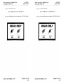
filler caps (serial nurnbers
344333042 and up)
I
AVGAS ONLY
GRADE
100LL
ISSUED: SEPTEMBER 23, 1983
ORADE
100
REPORT:
VB-1110
2-13
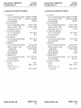
TABLE OF CONTENTS
SECTION
3
PROCEDURES
EMERGENCY
Page
No.
Paragraph
No
3.1
3.3
General
Emergency
........
........
............
Procedures Checklist..........
Airspeeds
for Safe Operations
Engine inoperative Procedures
Fire...-------Fuel Management During One Engine Inoperative
Operation
Engine Driven Fuel Pump Failure
Landing Gear Unsafe Warnings
Manual
Extension of Landing Gear
Gear Up Landing.............
Engine Failure With Rear Cabin and Cargo Doors
Removed
Electrical Failures
Gvro Suction Failures............
Spins
Emergency Descent
Combustion Heater Overheat
Open Door (Entry Door Only)
Propeller Overspeed.................,
Amplified
Emergency Procedures (General)
Engine looperative Procedures
Detecting A Dead Engine.........................
Engine Securing Procedure (Feathering Procedure)...
Engine Failure During Takeoff (Below 85 KIAS)
Engine Failure During Takeoff (85 KlAS or Above)
Engine Failure During Flight (Below 66 KIAS)
One Engine Inoperative Landing...........
One Engine inoperative Go-Around
Air Start (Unfeathering Procedure)
..........
.
.
.
.
.
.
.
.
.
.
.
.
.
.
.
.
.
.
--..................
--
--
..
...
...
.............
.
.............
...
.
.
.
3-6
3-7
3-8
3-8
3-8
.......
.................
...................
................
..................
.
...........
..........
.
.......
...........
..........
,........
-...........
........-..
..
.
.
.
.
.
.
.
,
.
.......
.
..
,
,
.......
...
3.5
33
.
.
...........
......
...........
......................
....
.
.
.
.
.
.
.
.......
.
.
.
.
.
.
.
.
.
.
.
.
.
.
.
.
.
.
.
.
.
.
.
.
.
,
,
,
,
.
,
,
REPORT:
3-I
3-2
3-2
3-2
3-6
3-9
3-9
3-10
3-10
3-f0
3-l I
3-I I
3-!!
3-13
3-13
3-13
3-13
3-14
3-15
3-15
3-16
3-16
3-16
VB-1110
3-i
TABLE OF CONTENTS
SECTION
3
(cont)
(cont)
Paragraph
Page
No.
No.
3.9
Fire........
..
...
Engine.Fire
.....
.....
On The Ground
.
3-17
3-17
3-17
.......
...........
.........
Engine Fire In-Flight...............
During One Engine Inoperative
Fuel Management
Operation
Cruising........
.............
3. I I
...........
Landing
3. I 3
3.15
3.17
3.19
3.21
..
.
..
.............
..
...
.
3.25
3.27
129
3.31
3.33
3,35
REPORT:
3-ii
.
3-17
3-18
3-18
3-18
3-19
3-19
3-20
..........
.
.........
.
.........
Engine Driven Fuel Pump Failure
Landing Gear Unsafe Warnings
Manual Extension Of The Landing Gear
Gear-Up Emergency Landing.............
Engine Failure With Rear Cabin and Cargo Doors
Removed
Electrical Failures
Gyro Suction Failures..........
Spins
Emergency Descent
Combustion Heater Overheat
Open Door
Propeller Overspeed..........
.
.....................
.............
..........
..........
23
.
.
..
........
.
.
.
.....
..........
......,...
.........
..
....,
...........
.....,.
.......
........
VB-Ill0
..
.......
.
,...
.
.
.
3-20
3-20
3-23
3-24
3-24
3-24
3-25
3-25
CORPORATION
PIPER AIRCRAFT
PA-34-220T, SENECA III
SECTION
SECTION
EMERGENCY
3
PROCEDURES
3
EMERGENCY PROCEDURES
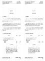
3.1 GENERAL
procedures for coping with various types of emerThe recommended
gencies and critical situations
are provided by this section. Required (FAA
procedures and those necessary for the operation
regulations).
emergency
oí the airplane as determined by the operating and design features of the
airplane are presented.
Emergency
equipment
which
with those optional
procedures associated
systems and
provided
require handbook supplements
by Section 9
are
(Supplementst
of this section consists of an abbreviated
emergency
which supplies an action sequence for critical situations with little
of systems.
on the operation
The first portion
checklist
emphasis
of the section
is devoted to amplified
emergency
The remainder
containing
information
additional
procedures
to provide the pilot with a
of the procedures.
more complete understanding
Pilots should familiarize themselves with the procedures given in this
action should an emergency
and be prepared
to take appropriate
arise.
section
procedures, such as power off landings, are a
Most basic emergency
part of pilot training. Although these emergencies are discussed here,
this information is not intended to replace such training, but only to provide
a source of reference and review, and to provide information on procedures
which are not the same for all aircraft. It is suggested that the pilot review
standard emergency procedures periodically to remain proficient in them.
normal
ISSUED: JANUARY
8, 1981
REPORT:
VB-1110
3-I
AIRCRAFT CORPORATION
PA-34-220T, SENECA
PIPER
SECTlON 3
EMERGENCY
PROCEDURES
PROCEDURES
3.3 EMERGENCY
III
CHECKLIST
FOR SAFE OPERATIONS
AIRSPEEDS
................66
One engine inoperative air minimum control
One engine inoperative best rate of climb
One engine inoperative best angle of climb
Maneuvering
KIAS
KIAS
78 KIAS
KlAS
KlAS
...................92
Never
exceed
.
-
..............
............
.
-
.
.
.
.
.
.
.
.
.
.
.
,
.
.
,
.
............140
.
..
............205
.
..
PROCEDURES
ENGINE INOPERATIVE
NOTE
The power on the operating engine
reduced when safe to do so
DETECTING
Loss of thrust.
Nose of aircraft
should
be
DEAD ENGlNE
will yaw in direction
of dead engine
(with coordinated
(FEATHERING
PROCEDURE)
controls).
PROCEDURE
ENGINE SECURlNG
............66
Minimurn control speed...............
One engine inoperative best rate of climb
Maintain direction and airspeed above 85
Mixture controls........
Propeller controls
Throttle controls............
KIAS
KIAS
.
...................92
KIAS.
...........forward
.
..
.
.
..
.
,
,
..
..
..
.........(40
..
Flaps............
Gear
Identify inoperative engine.
Throttle of inop. engine............
..
forward
in. Hg. Max.) forward
.
VB-1110
.
.
.
.
..
..
.............
...........
.,
retract
retract
............
.
....,.............
REPORT:
3-2
.
retard
ISSUED: JANUARY
to verify
8, 1981
PIPER AIRCRAFT CORPORATION
PA-34-220T, SENECA III
SECTION 3
PROCEDURES
EMERGENCV
to restore
power prior to feathering:
Mixtures...........
Fuel selector
Magnetos
Aux. fuel pump........
To attempt
required
..........as
.,
.
.
Ieft or right only
unlatch. ON HI, if
is not immediately
...........
............
..........
.
ON
..........
.........
power
restored
Alternate
air
..
..........
........
procedure.
feather before RPM
drops below 800
idle cut-off
as required (3° to 5° of bank
toward operative engine
ball I /2 to I out)
OFF
OFF
...........
..............
.
..............
.........
.
OFF
ON
with feathering
li power cannot b iestored continue
Prop control of inop. engine
Mixture of inop, engine...........
Trim
..........
-
-
Aux. fuel pump of inop. engine..........
Magnetos of inop. engine
..
..........
Cowl flaps
Alternator
close on inop, engine, as
required on operative engine
............
..............
of inop
.............
................
.
engine............
.
.
OFF
...........
...........reduce
Electrical load
Fuel selector
..
.
...........
OFF inop engine,
........
...........
consider
Aut fuel pump operative engine........
engine
Power of operative
.
ENGINE FAILURE
.
.
DURING
.
.
.
.
.
.
.
.
TAKEOFF
.
............,
JANUARY
8, 1981
.
.
.
,
OFF
,
.
,
as required
CLOSE both immediately
to stop:
If nadequate
runway remams
Throttles...............................................
Brakes......,.................................
Batterv switch
Fuelselectors..............
Continue straight ahead, turning to avoid obstacles.
ISSUED:
.
(Below 85 K1AS)
............
...
.
and 85 KIAS has not been attained:
li engine failure occurs during takeoff
Throttles..........
Stop straight ahead.
.
crossfeed
.........
....
.,......
..
CLOSED
apply max. braking
OFF
OFF
...........
..........
REPORT:
VB-IIIO
3-3
SECTION
3
EMERGENCY
PIPER AIRCRAFT CORPORATION
PA-34-220T, SENECA IH
PROCEDURES
(85 KIAS or above)
TAKEOFF
ENGINE FAll URE DURlNG
If engine failure occurs during takeoff ground roll or after lift-off with gear
stil down and 85 KlAS has been attained:
CLOSE
both throttles
immediately, land if
If adequate runway remains.
ahead,
airborne and stop straight
is inadequate for stopping, decide whether to abort
If runway remaining
maintain
is made to continue.
heading. After
continue,
decision
if
or
accelerate
establishing
to 92 KIAS, and
a climb. retract landing gear,
feather inoperative engine prop (see Engine Securing Procedure).
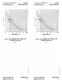
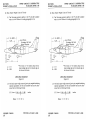
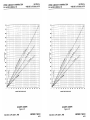
WARNING
of aircraft
combinations
weight,
In certain
ambient conditions
configuration,
and speeds,
negative climb performance may result. Refer
to One Engine Inoperative Climb Performance
Figure 5-21.
chart,
DURING
ENGINE FAILURE
Rudder
Throttles (both).............
Pitch attitude
,
.
.
.
.
.
.
.
.
.
........
.
.
Operative
engme
If altitude
permits. a restart
does not permit
.
.
apply
..........
.
.............
FLIGHT (Below 66 KIAS)
.
.
,
.
.
.
.
.
.
.
.
,
.
.
.
.
.
.
.
.
-
operative engine
retard to stop turn
lower nose to accelerate
above 66 KIAS*
mcrease power as airspeed
mcreases above 66 KlAS*
toward
-
-
fads or if altitude
may be attempted. If restart
Securing
Engine
Procedure.
see
restart,
ONE ENGINE 1NOPERATlVE LANDING
........feather
inop. engine prop
When certain of making field:
Landing gear
Wingflaps(assequired)
Maintain additional altitude and speed during approach.
Final approach speed
..........
.
..........extend
.....--....
..................lower
............
.........
*67
KIAS
with
aft doors
REPORT: VB-III0
3-4
.....
-
-
........90
----
KlAS
removed.
ISSUED: JANUARY
REVISED: FEBRUARY
8. 1981
25.1982
CORPORATION
PIPER AIRCRAFT
PA-34-220T, SENECA III
SECTION 3
PROCEDURES
EMERGENCV
GO-AROUND
ONE ENGINE INOPERATlVE
(SHOELD BE AVOIDED IF AT ALL POSSIBLE)
...........forward
Mixture
Propeller..........
Throttle
.
...........
.............forward
..
.........
(40 in. Hg. Max.) open slowly
...........
..
Flaps..........
landing
Airspeed
Trim
gear
retract
.........
..
retract
..........
.............
...........92
KIAS
,
.
...........
set
.....................................,..................
engine
Coni flap operating
as required
..............................
PROCEDURE)
AlR START (UNFEATHERING
Fuel selector inop. engine
fuel pump inop. engine
Throttle
Mixture
Magneto switches
Prop control
...........
....
.......
.
.
.
...........
Starter...........
Throttle
.................
.
,..........engage
.
.
.
..........
..........
............
............
...........
..........
.
.
.......
ON
LO boost
open 174 inch
RICH
ON
full forward
until propeller windmills
reduce power until engine
.........
.
.........
Aux.
............
is
Aux
luel pump..........
prime as required.
does not start,
(after restart)
Alternator
li engine
.........
..........
AIR ST ART (UNFEATHERlNG
On Airplanes
Fuel selector inop. engme
Aux fuel pump inop engine
Throule
Mixture
Magneto switches
Prop control & latch
Throttle
ON
PROCEDURE)
Unfeathering
With
Equipped
Accumulators
ON
LO boost
open I 4inch
RICH
ON
push full forward
power until engine
..........
.........
..........
......-...
.
..
...........
warm
OFF
...........
.
.........,
...........
..........
...........
...........
..........
...........
...........
..........
reduce
ts warm
Aux.fuel
pump..........
...........
.
ISSUED: JANUARY 8, 1981
REVISED: APRIL 9, 1982
OFF
REPORT: VB-1110
3-5
SECTION
If engine
Alternator
AIRCRAFT CORPORATION
PA-34-220T, SENECA III
PIPER
3
PROCEDURES
EMERGENCY
does not start, prime
(after restart)
as required.
and engage
.......,...
starter.
......
ON
.......,.
NOTE
The
starter
unfeathering
may be used in conjunction
accumulators
if required.
with the
FIRE
ENGINE FlRE ON GROUND:
If engine has not started:
Mixture
Throttle
Starter.............
idle
.............
..........
.
.
............
.
.
.
..
open
engine
crank
............
If engine has already started and is running, continue operating
the fire into the engine
If fire continues, extinguish with best available means.
If external fire extinguishing
is to be applied:
Fuel selector valves...........
Mixture
.......
cLit-off
...........
to try pulling
OFF
idle cut-off
.............
.
..
.
.
..
....
ENGINE FIRE IN FLlGHT
Affected
engine:
Fuel selector
Throttle
Propeller............
Mixture
OFF
...........
...........
close
...........
.........
feather
idle cut-off
OFF
OFF
......
.
.,.....-..
...........
Heater...........
Defroster
If terrain permits
..........
......
..........
..........
...
land immediately.
ONE ENGINE INOPERATIVE
FUEL MANAGEMENT DURING
OPERATION
CRUISING
using fuel from tank on the same side as the operating
operating
engine
selector
Fuel
engine:
When
,
REPORT:
3-6
VB-1110
.
.
.
.
.
.
.
.
.
.
.
..
.
.
.
.
.
ON
8, 1981
ISSUED: JANUARY
REVISED: APRIL 9, 1982
PIPER AIRCRAFT CORPORATION
PA-34-220T, SENECA Ill
Fuel
Aux.
selector
inop.
'uel
pumps
engme
.
.
.
.
.
...........
engine.
the operating
CROSSFEED
OFF
OFF
...........
...........
...........
3
OFF
OFF
.
.'.
..
When using fuel from tank on the side opposite
operating
engine
Fuel selector
inop. engine
Fuel selector
Aut fuel pumps.............
Use crossfeed
SECTION
PROCEDURES
EMERGENCV
..........
in level cruise flight only.
NOTE
Do not crossfeed with full fuel on same side as
return
operating
engine since vapor
fuel flow
will be lost through the vent system
LANDlNG
Fuel selector
Fuel selector
operating
inop, engme
DRIVEN
ENGINE
engine
.
.
.
.
.
.
.
.
.
.
.............
.
,
,
.
...........
.
..
.
.
.
,
ON
OFF
FUEL PUMP FAILURE
Throttle
Aux fuel pump...........
Throttle
retard
on HI
...........
.........
.........unlatch,
.
...........reset
.........
(7596
power or below)
CAUTION
If normal engine operation and fuel flow is not
the auxiliary fuel
immediately re-established,
off. The lack of a fuel
should
turned
be
pump
flow indication while on the Hl auxiliary fuel
pump position could indicate a leak in the
fuel system, or fuel exhaustion.
ISSUED: JANUARY 8, 1981
REVISED: APRIL 9, 1982
REPORT:
VB-Ill0
3-7
SECTION
PIPER AIRCRAFT CORPORATION
PA-34-220T, SENECA Ill
3
PROCEDURES
EMERGENCY
CAUTION
auxiliary
fuel pumps if vapor
is required (LO position) or the
engine driven fuel pump fails (H1 position).
fuel pumps have no standby
The auxiliary
function. Actuation of the Hl switch position
when the engine fuel injection system is functioning normally may cause engine roughness
due to excessively rich fuel air mixture.
the
Actuate
suppression
WARNINGS
GEAR UNSAFE
LANDING
Red light indicates gear in transit.
Recycle gear if indication continues.
Light will illuminate when gear warning
OF LANDING
EXTENSION
MANUAL
Check following before
Circuit breakers
-
Battery switch
Alternators..........
-
-
-
extending
-
-
-
-
-
-
-
settings.
GEAR
gear manually:
-
.
.
.
.
.
.
.
.
.
.
.
.
.
.
.
.
.
.
.
,
..........
..........
check
ON
...........check
.
lights
Navigation
-
-
horn sounds at low throttle
.
.
.
,
To extend. reposition
Airspeed
Gear selector
...........
,
,
.
.
.
.
.
clip downward
OFF
(daytime)
.
.
.
clear of knob and proceed as follows:
reduce (85 KIAS max.)
GEAR DOWN
LOCKED position
..........
.
.........
..........
Emerg. gear extend knob
Indicator lights
Leave emergency gear extension
...........,
...........
..............
.
....
...
..........
pu]\
3 green
knob out.
GEAR UP LANDING
Approach
Flaps...........
Throttles.........
..........
...........
REPORT:
3-8
VB-Il10
..........
...........closed
Normal
as desired
prior to
touchdown
ISSUED: JANUARY 8, 1981
REVISED: APRIL 9, 1982
CORPORATION
PIPER AIRCRAFT
PA-34-220T, SENECA IH
Bauert
Fuel
switch
....
....
selector
.....
.
..
.
Eauch down at minimum
If airspeed
.
.....
speed
.
.....
,......
..
3
OFF
OFE
airspeed.
WITH
ENGINE FAILURE
REMOVED
S.E. min. control
SECTION
PROCEDURES
EMERGENOV
CABIN
REAR
AND
CARGO
DOORS3
of 67 KIAS for this configuration.
is below 67 KlAS reduce power
on operating
engine to maintain
contro!
FAILURES
ELECTRICAL
light illuminated:
ALT warning
Ammeter Ammeters.......
Electrical load
,..........
Ahernators..........
ti
alternator
Batters
Alternator
..............
.................
outputs
switch
...........
.
..
..
check L & R.check
reduce to minimum
OFF. then ON one at a time
are NOT restored:
switches........
........
alternator
outputs
are NOT restored:
switches..........
\\ternator
Baners switch
OFF
..........
....
...........
OFF, then ON one
at a time
li
,
-
..........
li
alternator
pracucal.
........
.....as
...
OFF
required
cannot be restored, reduce electrical load and land as soon as
of electrical power.
source
The battery is the only remaining
WARNING
Compass error
both alternators
may exceed
inoperative.
10 degrees
with
NOTE
If battery is depleted, the landing gear must be
using
the emergency
lowered
gear extension
procedure. Gear position lights will be inoperative.
ISSCED: JANUARY 8. 1981
REVISED: AUGUST 9, 1982
REPORT:
VB-1110
19
AIRCRAFT CORPORATION
PA-34-220T, SENECA III
PIPER
SECTION
3
EMERGENCY
PROCEDURES
Electrical overload
Electrical load
(alt
nators
.......
over 30 amps above
electrical
known
.
.
.
load):
reduce
.........
.
be reduced:
loads cannot
If alternator
Battery switch
...
.........
OFF
............
If alternator loads are not reduced, land as soon as possible.
Anticipate
complete electrical power failure.
F.AILURES
GYRO SUCTION
Pressure below 4.5 in. Hg.
RPM.............
Altitude
............increase
.
.
...........
,
to monitor
Use electric turn indicator
Indicator
performance.
to
.
.
2600
descend to maintain
4.5 in Hg.
Indicator and Attitude
............
Directional
SPINS
Throttles............
Rudder
Ailerons
Rudder
........
.
Control wheel
Control wheel
retard to idle
full opposite to
direction of spin
release
back pressure
full forward if
nose does not drop
neutral
.........,.
..
..........
...........
..........
...........
...........
...........
..........
...........
neutralize
rotation
............
when
stops
..........smooth
Control wheel
........
back pressure
from dive
.
to
recover
DESCENT
EMERGENCY
Throttles..........
Propellers............
Mixture
.
closed
...........
full forward
required for
..........
..........,as
.
..........
smooth
operation
..........extend
Landing gear
Airspeed
REPORT:
3-10
..
........
..
....-,....130
KIAS
.....-...
VB-1110
ISSUED: JANUARY 8. 1981
REVISED: APRIL 9, 1982
PIP£R AIRCRAFT CORPORATION
PA-34-220T, SENECA III
COMBUSTION
HEATER
SECTION
3
PROCEDURES
EMERGENCY
OVERHEAT
cut-off.
l nit will automatically
restart.
Do not attempt
to
DOOR ONLY)
OPEN DOOR (ENTRY
If both upper and side latches are open, the door will trail slightly
airspeeds wil be reduced slightly.
open and
To lose the door in flight:
SÌon airplane
to 90 KIAS.
Cab n tents
window............
Stor
.........
.
..
lf upper laich is open..............
lf side latch is open
if both latches are open...........
Throule
Prop control
........
Airspeed
latch side latch
then top latch
............
..
.
...........
retard
......-...full
DECREASE
.
..........
rpm,
then set if any
control avaËlable
reduce
required
remain
as
to
below 2600 rpm
.............
...........
.
latch
...............
pull on arrnrest while
moving latch handle
to latched position
.
.
open
..........
OVERSPEED
PROPELLER
Throtile
.
.
..........
...........
close
...........
.
.
.
.
.
.
.
.
.
.
ISSUED: JANUARY 8, 1981
REVISED: APRIL 9, 1982
,
,
.
.
-
.
,
,
.
.
.
REPORT: VB-III0
3-11
SECTION 3
EMERGENCY
PROCEDURES
PIPER AIRCRAFT CORPORATION
PA-34-220T, SENECA III
THIS PAGE INTENTIONALLY
REPORT:
3-12
VB-1110
LEFT
ISSUED:
BLANK
JANUARY
8, 1981
PIPER AIRCRAFT CORPORATION
III
PA-34-220T. SENECA
15 AMPLIFIED
EMERGENCY
SECTION 3
PROCEDURES
EMERGENCY
PROCEDURES
(GENERAL)
additional
presented
The following paragraphs
to supply
are
information for the purpose of providing the pilot with a more complete
understanding
of the recommended
course of action and probable cause of
an emergency
situation.
3.7 ENGINE INOPERATIVE
DETECTING
A DEAD
PROCEDURES
ENGINE
controls,
A loss of thrust will be noted and with coordinated
the aircraft will yaw in the direction of the dead engine.
ENGINE SECURING
PROCEDURE
(FEATHERING
the nose of
PROCEDURE)
Keep in mind that the one engine inoperative air minimum control
speed is 66 KIAS and the one engine inoperative best rate of climb speed is
92 KlAS.
direction and an airspeed above 85
To feather a propeller. maintain
Move the mixture and propeller controls forward The throttle
controls should be moved forward to maimain a safe airspeed. Retract the
flaps and landing gear and identify the inoperative engine. The airplane will
yan in the direction of the dead engine. Retard the throttle of the inoperative
engine to serify loss of power
KlAS.
NOTE
If circumstances
permit. in the event of an
actual engine failure, the pilot may elect to
attempt
to restore power prior to feathering.
If circumstances
permit an attempt to restore power prior to feathering,
adjust the mixture control as required, move the fuel selector control to ON,
and select either L (left)or R (right)magneto. Move the ALTERNATE AIR
control to ON and the AUX. fuel pump to the ON-HI position if power is
turn off the AUX. fuel pump.
not immediately restored
ISSUED:
JANUARY
8, 1981
REPORT:
VB-1110
3-13
SECTION
3
PIPER
AIRCRAFT
PROCEDURES
EMERGENCY
CORPORKTION
PA-34-220T, SENECA 111
only while the engine is rotating above
centrifugal
of
force
due
800 RPM. Loss
to slowing RPM will actuate a stop
pin that keeps the propeller from feathering each time the engine is stopped
all
performance
decrease if the
on the ground. One engine inoperative
of the inoperative engine is not feathered.
propeller
The propeHers can be feathered
The propeller
control
of the inoperative engine should
be moved to the
comrol of the inoperative engine to idle
feather position and the mixture
cut-off.
Trim the aircraft as required and maintain a 3° to 5° hank toward the
engine. The ball wil be V to I out for minimum
drag. The AUX.
fueÏ pumps should be off except in the case of an engine driven fuel pump
failure. Turn OFF the magnetos and close the cowl flaps on the inoperative
engine,
Cowl flaps should
be used as necessary on the operative engine.
of the inoperative engine should be turned OFF and the
The alternator
electrical load reduced to prevent depletion of the battery. Move the fuel
selector
control for the inoperative engine to the OFF position. If necessary.
consider the use of crossfeed (refer to Fuel Management During One Engine
lnoperati-ve Operation, paragraph 3. I I). Turn OFF the operative engine's
AUX. fuel pump.
operating
NOTE
an engine is feathered
air.
and oil annunciator
gyro
will remain illuminated.
When
ENGlNE
FA1LURE
DURlNG
TAKEOFF
The one engine inoperative air minimum
is 66 K lAS under standard conditions.
the alternator.
warning
lights
(BELOW
control
85 KIAS)
speed
for this airplane
If engine failure occurs during takeoff ground rol and 85 KlAS has not
been attained. CLOSE both throttles immediately and stop straight ahead.
If inadequate
remains
and apply
to stop, close the throttles
runway
maximum
braking. The battery switch and fuel selectors should be turned
OFF. Continue path straight ahead turning to avoid obstacles as necessary
REPORT:
3-14
VB-Il10
ISSUED:
JANUARY
8, 1981
PIPER AIRCRAFT CORPORATION
PA-34-220T. SENECA III
ENGINE
EAILURE
DURING
SECTION
EMERGENCY
TAKEOFF(85
3
PROCEDURES
KIAS OR ABOVE)
It engine failure occurs during takeoff ground roll or after lift-ofT with
to be
the year still down and 85 KIAS has been attained, the course 01action
will depend on the runway remaining.
If adequate
taken
runway remains.
and stop straight
immediately, land if airborne
C1.OSE both throttles
ahead
If the runway remaining is inadequate for stopping. the pilot must
The decision must be
to abort the takeoff or to continue.
decide whether
loading.densityaltitude.obstruebacd on the pilors judgment considering
If the decision is made to
and the pilot-s competence.
tions. the weather.
When climb is estabcontinue the takeoff. maintain heading and airspeed.
KlAS, and FEATHER
the landinggear.accelerate1092
hshed RETRACT
engine
(refer to Engine Securing Proceduret
the moperative
WARNING
of aircraft
weight,
ln certain combinations
and speeds,
configuration,
ambient conditions
negative climb performance may result. Refer
to One Engine lnoperative
chart, Figure 5-21.
ENGINE
FAILURE
DURING
FLIGHT
Climb Performance
(BELOW 66 KLAS)
Should an engine fail during flight at an airspeed below 66 KIAS.apply
towards
the operative engine to maintain directional controL The
should
throule,
to stop the yaw force produced by the
be retarded
engine. Lower the nose of the aircraft
to accelerate above 66
maperame
engine
operative
the
the
and
as the airspeed
increase
KLAS
power on
exceeds 66 KIAS*.
rudder
Aner an airspeed above 66 KIAS* has been established,
an engine
attempt may be made if altitude permits. If the restart hasfailed,orif
aMtude does noi permit, the engine should be secured, see Engine Securing
restan
Procedure.
*6"
KIAS with aft doors removed.
ISSUED: JANUARY 8, 1981
REVISED: FEBRUARY 25, 1982
REPORT:
VB-1110
3-15
PIPER AIRCRAFT CORPORATION
PA-34-220T, SËNECA IH
SECTION
3
EMERGENCY
PROCEDURES
LANDING
ONE ENGINE INOPERATlVE
Complete the Engine Securing Procedure. The landing gear should not
be extended and the wing flaps should not be lowered until certain of making
the field.
altitude and speed
Maintain additional
mind that landing should
be made right the
should be avoided if at all possible.
speed
Establish a final approach
during approach,
first time
keeping in
and that a go-around
of 90 KlAS and
use wing flaps as
required.
WARNING
Under some conditions of loading and density
altitude a go-around may be impossible. and in
of power
any event the sudden application
during one engine inoperative operation makes
control of the airplane more difficult.
ONE ENGINE lNOPERATlVE
GO-AROUND
NOTE
A one engine inoperative go-around
avoided if at all possible,
should
be
To execute
a one engine inoperative go-around. advance the mixture
and propeller levers forward. The throttle should be advanced slowly to 40
in. Hg. manifold pressure. Retract the flaps and landing gear. Maintain
airspeed at the one engine inoperative best rate of climb speed of92 KIAS.
Set the trim and cowl flaps as required.
AIR START
(UNFEATHERlNG
PROCEDURE)
Move the fuel selector for the inoperative engine to theON position and
check to make sure the AUX fuel pump for that engine is on LO boost. Open
the throttle
1,4 inch and the mixtures should be set RICH. Turn ON the
and push the propeHer control latch and propeller control
switches
magneto
lever full forward. On airplanes equipped with the optional unfeathering
not so equipped,
system the propeller will start to windmilL On airplanes
REPORT:
3-16
VB-1110
ISSUED: JANUARY 8, 1981
REVISED: APRIL 9, 1982
PIPER AIRCRAFT CORPORATION
III
PA-34-220T, SENECA
SECTION
EMERGENOV
3
PROCEDURES
engage the starter until the propeller windmills freely. If the engine does not
start. prime as necessary. After restart turn OFFthe AUX tuel pump, reduce
switch ON.
the power until the engine is warm and turn the alternator
If required
accumulators.
the starter
may be used in conjunction
with
the unfeathering
3.9 FIRE
ENG1NE FIRE ON THE GROUND
the fire is to try to draw the fire back into
The first attempt to extinguish
If the engine has not started move the mixture control to idle
the engine.
cut-off and open the throttle, Begin to crank the engine with the starter in an
attempt to pull the fire into the engine.
lí the engine has already started
the fire into the engine.
and is running,
continue
operating
to
try to pull
if the fire continues longer than a few seconds the
In either case(above),
by the best available external means.
fire should be extinguished
method is to be applied
It an external fire extinguishing
talves
to OFF and the mixture to idle cut-off.
move the fuel
selector
ENGINE FIRE
IN-FLIGHT
The procedure given below is general and pilot judgment should be the
factor for action in such an emergency.
deciding
li an engine fire occurs in flight, place the fuel selector of the affected
engine in the OFF position. Feather the propeller on the faulty engine. Move
the mixture control to idle cut-off. The cowl flap should be open. A landing
should be made if terrain permits.
3.11 FUEL MANAGEMENT DURING ONE ENGINE INOPERATIVE
OPERATION
A crossfeed is provided to increase range during
operation
Use crossfeed in level flight only.
ISSEED: JANUARY 8, 1981
REVISED: APRIL 9, 1982
one engine inoperative
REPORT:
VB-ll10
3-17
SECTION
PIPER
3
EMERGENCV
PROCEDURES
AIRCRAFT CORPORATION
PA-34-220T, SENECA III
CRUISlNG
When using fuel from the fuel tank on the same side as the operating
engine shouki be ON and the fuel
of the operating
engine the fuel selector
should
be OFF. The AUX. fuel pumps
engine
inoperative
selector for the
should be OFF except in the case of an engine driven fuel pump failure. If
an engine driven fuel pump has failed the AUX fuel pump on the operating
engine
side must be ON
H l.
-
lucreased range is available by using fuel from the tank on the opposite
side of the operating engine. For this configuration the fuel selector of the
engine should be on X-FEED icrossfeed)
operating
and the fuel selector of
the inoperative engine should be OFF. The AUX, fuel pumps should be
OFF.
NOTE
A vapor return line from each engine will return
a percentage of fuel back. to the tank on the
same side as that engine. Therefore, a minimum
of 30 minutes of fuelshould be used from this
tank before selecting crossfeed, If the tank
"FULl
gauge approaches
go back to that
for 30 minutes to bring the
tank and operate
fuel level down before returning to crossfeed or
fuel raay be pumped overboard through the
fuel vent.
LANDING
During the landing sequence the fuel selector of the operating engine
must be ON and the fuel selector of the inoperative engine OFF. The AUX.
fuel pump of the operating engine should be OFF.
3.13 ENGINE DRIVEN
FUEL
PUMP FAILURE
of the engine driven fuel pump occur, the
Should a malfunction
fuel pressure for engine
fuel pump system can supply sufficient
of RPM and Manifold
combination
approximately
75
Any
to
up
power
used, but leaning
Table
be
may
Pressure defined on the Power Setting
may
altitudes
above
15,000
operation
at
feet or for R PM's
required
smooth
for
be
procedures should be
below 2300. Normal cruise. descent and approach
auxiliary
used.
REPORT:
3-18
VB-Illo
ISSUED: JANUARY 8, 1981
REVISED: APRIL 9, 1982
PIPER AIRCRAFT CORPORATION
PA-34-220T, SENECA III
EMERGENCY
SECTION
PROCEDURES
3
Loss of fuel pressure and engine power can be an indication of failure
of the engine driven fuel pump Should these occur and engine driven fuel
unlatch the auxiliary
pump failure is suspected, retard thethrottleand
pump
and select the Hl position. The throttle can then be reset at 759 power or
below.
CAUTIONS
If normal engine operation and fuel flow is not
the auxiliary
immediately re-established.
fuel
off.
lack of a fuel
should
turned
The
be
pump
flow indication while on the Hl auxiliarv fuel
pump position could hidicate a leak in the fuel
system. or fuel exhaustion.
fuel pumps if vapor
Actuate the auxiliary
suppression
is required (LO position) or the
engine driven fuel pump fails (HI position).
The auxiliary
fuel pumps have no standby
of the HI switch position
function. Actuation
normally
when the engines are operating
may
and or power loss.
cause engine roughness
3.15 LANDING
GEAR UNSAFE
WARNINGS
when the landing gear is in
The red landing gear light will illuminate
transition
between the full up position and the down and locked position.
illumination of the
The pilot should recycle the landing gear if continued
the light will illuminate when the gear warning
licht occurs. Additionallv,
horn sounds. The gear warning horn will sound at low throttle settings ifthe
gear is not down and locked.
3 17 MANUAL
EXTENSION
OF THE LANDING
GEAR
the landing gear
Several items should be checked prior to extending
manually. Check for popped circuit breakers and ensure the battery switch is
ON. Now check the alternators.
lf it is daytime. turn OFF the navigation
lights.
ISSUED: JANUARY 8, 1981
REVISED: APRIL 9, 1982
REPORT:
VB-1110
3-19
SECTION
PIPER
3
PROCEDURES
EMERGENOV
AIRCRAFT CORPORATION
DI
PA-34-220T, SENECA
of the landing
gear, power should be
a manual extension
85
KlAS.
the landing gear
Place
maintain
airspeed
below
to
selector
switch in the GEAR DOWN position and pull the emergency gear
lights.
exterision knob. Check for 3 green indicator
To execnic
reduced
WARNING
ff the emergency gear extension knob has been
pulled out to lower the gear due to a gear system
malfunction.
lease the control in its extended
until the airplane
has been put on
position
jacks to check the proper function of the
landing gears hydraulic and electrical systems.
3.19 GEAR-UP
LANDING
EMERGENCY
An approach should be made with power at a normal airspeed with the
flap position to be used at the pilot's discretion. Flaps up will reduce wing
Turn OFF the
flap damage. Close the throttles just before touchdown.
valve
selector
controls to
switches
the
and
fuel
and
ignition
battery
move
OFF. Contact to the surface should be made at a minimum airspeed.
3.21
WITH REAR CABIN
ENGINE FAILURE
REMOVED
AND CARGO DOORS
The minimum smgle engine control speed for this configuration
KlAS If engine failure occurs at an airspeed below 67 KIAS. reduce
as necessary on the operating
tional controL
3.23 ELECTRlCAL
SN
engine
and apply
rudder
to maintain
is 67
power
direc-
FAILURES
344 I 3300 I THRU
34-8233205
light illuminates, observe the ammeters to
If both ammeters show zero
is inoperative.
Turn OFF both abernator
output. reduce electrical loads to the minimum.
ON
and
them
switches
momentarily
then turn
one at a time while obsen ing
showing the LEAST (but not Jero) current
the ammeters.
The alternator
should
be left OFF. Electrical
should be turned ON The other alternator
If an ALT annunciator
determine which alternator
REPORT:
3-20
VB-1110
ISSUED: JANUARY
8. 1981
REVISED: AUGUST 4, 1982
PIPER AIRCRAFT CORPORATION
PA-34-220T. SENECA III
SECTION
EMERGENCV
3
PROCEDURES
lí both
of 60 amperes.
loads may be reinstated
as required to a maximum
switches
should be
hoth alternator
outputs
alternator
cannot be restored.
and land as soon as
load to essential
systems
left OFE. Reduce the electrical
of electrical
practical.
1he battery is the only remaining
source
power.
then ON. If
cycle its switch OFFand
If one ammeter shows zero output.
check the circuit breakers. The breakers may be
this faHs to restore output
remains inoperative reduccelectrical
If the alternator
reset once il required.
flight.
leads if necessary and exercise judgment regarding continued
maintenance
Correctite
actions
should
be performed
prior to further
Ilichts.
NOTE
The markings
require
mental
ampere
values
(loadmeters)
interpolations to estimate the
noted. Operating the alternators
on the ammeters
will assure
at less than 60 amperes
battery will not be depleted.
that
the
WARNING
Compass
alternators
error may exceed
moperative.
10° with
both
If abnormally
high alternator
outputs are observed and persists (more
electrical
loads) they may be caused by a low
above
known
30 amps
electrical
abnormal
load. If it is caused bya
other
fault.
battery
or
bauer
a
normal within 5
low baners the indication should begin to decrease towards
with
the
observed
this
following..
condition
proceed
Turn the
is
minutes
R
batters switch OFF and the afternator
output indications should decrease.
output indications not
Turn the battery switch ON. Should the alternator
lease the battery switch OFF and land as soon as practical. All
decrease,
Also anticipate complete
electrical ioad
being supphed by the alternators.
than
electrical
power
failure.
NOTE
ON and the
Operation with the alternator
be made only when
battery switch OFF should
required by electrical failure, due to increased
system voltage and radio frequency noise.
8, 1981
AUGUST 9, 1982
ISSUED: JANUARY
REVISED:
REPORT:
VB-1110
3-21
i
SECTION
3
EMERGENCY
SN
34-N333001
CORPORATION
PA-34-220T. SENECA III
AIRCRAFT
PIPER
PROCEDURES
AND UP
hght illuminates check the output of each
ALT annunciator
using
indisiduallv,
the
alternator
prss to-test buttons located on either side
which
If both
is inoperalive.
of the ammeter
to determine
show zero output. reduccelectricalloads
alternators
to the minimum. Turn
switches and then turn them rnomentarily
ON one at a
OFF both alternator
output.
The alternator showing the LEAST
time while obscr ing alternator
should
be
(but not zero) current should be turned ON. The other alternator
maximumof60
reinstated
required
loads
toa
Electrical
be
as
left OFF.
may
both alternator
be restored,
If both alternator
outputs cannot
amperes.
should
switches
be left OFE, Reduce the electrical load to essential systems
and land as soon as practical. The battery is the only remaining
source of
electrical power.
if
an
..uternator
cycle its switch OFF and then ON.
shows zero-output,
If one alternator
If this fails to restore output check the circui.t breakers. The breakers may be
If the alternator
remains inoperative reduce electrical
reset once if required.
flight.
loads if necessary and exercise judgment regarding continued
When the ammeter needle indicates to the left of center. the battery is
being discharged; when the needle indicates to the right of center, the battery
is being charged. During single alternator operation the feature can be used
be reduced.
to determine how much the electrical load should
Correctne
flights
maintenance
actions
should
be períormed
prior to further
NOTE
The markings
require
mental
ampere
values
at less than
battery
will
an
the
ammeter
(loadmeter)
interpolations to estimate the
noted. Operating thealternators
60 amperes
will
assure
that
the
not be depleted.
WARNING
Compass
alternators
REPORT:
3-22
VB-ll10
error
may
exceed
10° with
both
inoperative.
ISSUED: JANUARY 8. 1981
REVISED: AUGUST 9, 1982
CORPORATION
PIPER AIRCRAFT
Ill
SENECA
PA-34-220T,
SECTION
EMERGENOV
3
PROCEDURES
and persists (more
outputs are observed
high alternator
known electrical loads) they may be caused by a low
electrical load, if it is caused bya
battery. a banery fault, or other abnorrud
low batters the indication should begin to decrease towards normal within 5
proceed with the following. Turn the
is observed
minutes. Il this condition
output indications should decrease.
battery switch OFF and the alternator
alternator
the
switch
Should
output indications not
ON.
Turn the battery
decrease,
lease the battery switch OFF and land as soon as practical. All
Also anticipate complete
by the alternators.
electrical load is being supplied
electrical power failure.
If abnormally
than
10 amps
above
NOTE
ON and the
Operation with the alternator
battery switch OFF should be made only when
required by electrical failure. due to increased
voltage
and radio frequency noise.
system
3.25 GYRO SUCTION
FAILURES
of the instrument suction system will be indicated by a
A maltunction
in the event of a vacuum
of the suction reading on the
reduction
warning
engine,
light on the
vacuum
low
a
tem failure or a feathered
panel will illuminate.
annunciator
.gauge.
(suction lower than 4.5
In the erent of a suction system malfunction.
2600.
Descend
engine
PM
to an altitude at
R
to
of
mercury)
increase
inches
suction can be maintained. if possible. The
of
4.5
inches
hich
mercury
w
of the
electric turn indicator should be used to monitor the performance
attitude
indicators.
and
direedonal
ISSUED: JANUARY 8, 1981
REVISED: AUGUST 9, 1982
REPORT:
VB-1110
3-23
SECTION
3
EMERGENCY
3.27
PROCEDURES
PIPER AIRCRAFT CORPORATION
PA-34-220T. SENECA Ill
SPINS
spins are prohibited in this airplane,
in the event a spin is
unintentionally.
immediate recovery actions must be taken.
Intentional
encountered
spin, immediately retard thethrottles
To recover irom an unintentional
rudder
opposite
Apply
the direction of the spin
full
the
idle position.
to
rotation
Let up all back pressure on the control wheel If the nose does not
drop, immediately push the control wheel full forward. Keep the ailerons
neutral. Maintain the controls in these positions until spin rotation stops,
should be with
then neutralize the rudder. Recovery from the resultant.dive
smooth back pressure on the control wheet No abrupt control movement
should be used during recovery from the di-ve. as the positive limit maneuvering
load factor may be exceeded,
NOTE
Regulations
Federal Aviation Admi-nistration
spin demonstration
of multido not require
engine airplanes, therefore, spin tests have not
technique
conducted.
been
The. recovery
presented
is based on the best available
information.
3.29 EMERGENCY
DESCENT
In the event an emergency descent becomes necessary, CLOSE the
Adjust the
full FORWARD.
throttles and move the propeller controls
operation.
mixture
controls
Extend. the
to attain smooth
as necessary
landing gear at 130 KIAS and mairnain this airspeed.
3.31 COMBUSTION
HEATER
OVERHEAT
the fuel. air and ignition to the
In the event of an overheat condition,
cut off. Do not attempt
heater is automatically
to restart the heater until it
has been determined
has been inspected and the cause of the malfunction
and corrected.
REPORT:
3-24
VB-1110
ISSUED:
AUGUST 9. 1982
PIPER AIRCRAFT CORPORATION
PA-34-220T, SENECA III
OPEN DOOR
3.33
(ENTRY
DOOR
SECTION
EMERGENCY
3
PROCEDURES
ONLY)
The cabin door is double latched, so the chances of its springing
open in
at both the top and side are remote.
However, should you forget the
upper latch. or not fully engage the side latch, the door may spring partially
A partially open
open. This will usually happen at takeoff or soon afterward.
and a normal landing can
door will not affect normal flight characteristics.
be made with door open.
lUght
and
If both upper and side latches are open,
airspeed will be reduced slightly.
the door will
trail
sBglit]y
open,
slow the airplane to 90 K IAS.close the cabin
If the top latch is open. latch it. If theside
window.
the
storm
and
vents
open
latch is open, pull on the armrest while moving the latch handle to the
latched position. If both latches are open, close the side latch then the top
To close the door in flight,
latch,
3.35 PROPELLER
OVERSPEED
in the propeller
Propeller overspeed is usually caused by a malfunction
governor
w hich allows the propeller blades to rotate to full low pitch
If propeller overspeed should occur. retard the throttle. The propeller
rpm" and then set if any
omrol should be moved to full "DECREASE
Airspeed
should
be reduced
and throttle
used to
control
is asailable.
maimain
300 RPM.
ISSUED:
AUGUST 9, 1982
REPORT
VB-Ill0
3-25
TABLE OF CONTENTS
SECTION
NORMAL
4
PROCEDURES
Page
Paragraph
No.
4.1
43
4.5
No.
General
Airspeeds For Safe Operations
Normal Procedures Checklist........................
Preparation.............
Prenight Check............
Before Starting Engines
Starting Engines (Airplane Equipped With
Standard Primer System)
Starting Engines (Airplane Equipped With
Optional
Engine Primer System)
Starting Engines When Flooded
Starting Engines in Cold Weather (Airplane
With Standard Engine Primer System)
Equipped
With External Power
Engines
Starting
Warm-Up
Taxiing.....,.........
Ground Check
Before Takeoff
Takeoff
Climb
Cruising
Descent
and Landing...........
Approach
4-!
...........
..,...............
4-2
4-3
4-3
4-3
........
...-.........
.......
.
............
..............
4-5
.........
.
4-5
.........
...............
.
.
.
.
.
,
,
.
.
.
.
.
.
.
.
.
,
4-6
,
4-7
...................
.
.
.
.
.
.
.
....
.
.
.
.
-
.........
.
.
.......
..........
4-11
4-11
.........
...........
.........
..........
...........
.............
.........
Go-Around
.
...........
After Landing.........
Shutdown
Mooring........................Amplified
Normal Procedures
4.7
..........
..........
.
...........
..........
.........
(General)
.......
4-7
4-8
4-9
4-10
........
.........
.
4-8
4-8
...........
..........
.....
.
......
REPORT:
4-11
4-12
4-12
4-12
4-12
4-13
4-l5
VB-1110
4-i
TABLE OF CONTENTS
SECTION
4
(cont)
(cont)
Page
No.
Paragraph
No.
4,23
Preparation...........
Preflight Check............
Before Starting Engines
Starting
Engines (Standard Primer System)
Starting Engines (Optional Primer System).
Starting Engines When Elooded
Sutrting Engines In Cold Weather (Standard
Primer System)............
Starting Engines With External Power
4.25
Preheating..........
4.27
4.29
4.31
4.33
Warm-Up
4.9
4.fl
4 13
4.15
4.17
4.19
4.21
.
.
4.35
4.37
4.39
4.41
4.43
4.45
4.47
4.49
4.5|
4.53
4.57
4.59
.
.
.
.
.
.
.
.
.
.
.
.
.
.
.
.
.
.
.
.
4-20
.
.
.
.
...
.
.
.
.
.
...,..
..........
Taxiing..........
Before Takeoff
Takeoff
Climb.....
Cruising..........
Descent
...--
....
..
Ground Check
-
..........
.
,
,
.
......
.
..........
.
.....
........
..
..,.
......
.......
..
and I.anding........
Approach
Go-Around
After Landing.......
..
....
..........
.
.
Shutdown
Mooring.........
Turbulent Air Operation,,..
Flight With Rear Cabin and Cargo Doors
......
........
...
....
Remo\ed
Intentional
Minimum
Vms
Stalls
YssE
REPORT:
4-ii
-
-
.........
VB-1110
....,.
....
......
..
.
..
.
......
.
......
.
.........,
Speed
One Engine inoperative
Single Engine Control Speed
.
.
4-16b
4-17
4-18
.
...........
.
.........
..
4.55
.
..........
.....
.
......
..
.
..........
.
4-16
......
................
.
4-l5
.........
.
.....
,
.
.
.
.
.
.
.
.
......
.
.
.
.
.
.
4-20
4-21
4-2]
4-24
4-25
4-25
4-27
429
4 29
4 3)
4 32
4-34
4-34
4-34
4-35
4 35
4-35
4-36
4-36
4-3N
SECTION
PIPER AIRCRAFT CORPORATION
III
PA-34-220T, SENECA
SECTION
NORMAL
4
PROCEDURES
NORMAL
4
PROCEDURES
4.1 GENERAL
procedures for normal
This section describes the recommended
for the Seneca 111.Required (FAA regulations) procedures and
of the airplane
as determined by the
those necessary for the operation
operating
and design features of the airplane are presented.
operations
with those optional systems and equipNormal procedures associated
supplements
require
which
handbook
are provided by Section 9
ment
(Supplements).
These procedures are provided to present a source of reference and
retiew and to supply information on procedures which are not the same for
Pilots should familiarize themselves with the procedures given
all aircraft.
section
this
in order to become proficient in the normal operations of the
in
airplane.
The first portion of this section consists of a short form checklist which
with little emphasis on
suppbes an action sequence for normal operations
of the systems,
the operation
of the section is devoted to amplified normal procedures
The remainder
of the procedures and
which provide detailed information and explanations
of
section
is
portion
the
not intended for use as
how to perform them. This
explanations.
lengthy
The short form checkm-flight
reference
due
the
to
an
list should be used for this purpose.
All data given is for both two and three blade propellers
unless otherwise
noted.
ISSUED: JANUARY
8, 1981
REPORT:
VB-1110
4-1
SECTION
NORMAL
PIPER
4
PROCEDURES
4.3 AIRSPEEDS
AIRCRAFT CORPORATION
PA-34-220T, SENECA III
FOR SAFE OPERATIONS
The following airspeeds are those which are significant
of the airplane.
These figures are for standard airplanes
conditions
weight under standard
at sea level.
to the operation
flown at gross
Performance for a specific airplane may vary from published figures
of the engine,
installed, the condition
depending upon the equipment
conditions
atmospheric
and piloting technique.
and equipment,
airplane
of Climb Speed
Best Angle of Climb Speed
Turbulent Air Operating Speed (See
Subsection 2.3)
Maximum Flap Speed
Landing Final Approach Speed (Flaps 40°)
Short Field Effort
Intentional One Engine lnoperative Speed
Maximum Demonstrated Crosswind Velocity
(a) Best Rate
(b)
(c)
(d)
(e)
(f)
(g)
REPORT:
4-2
VB-1110
ISSUED:
JANUARY
92 KIAS
76 KIAS
140 KIAS
i15 KIAS
82 KIAS
85 KIAS
17 KTS
8, 1981
PIPER AIRCRAFT CORPORATION
PA-34-220T, SENECA III
SECTION 4
PROCEDURES
NORMAL
WALK-AROUND
Figure 4-!
PROCEDURES
4.5 NORMAL
CHECKLIST
PREPARATION
..........airworthy,
Airplane status
Weather
Baggage
Weight and C.G..........
papers on board
.........
............suitable
..........
.
.
.
.
.
.
.
.
.
.
.
.
.
.
.
.
.
.
.
weighed,
.
stowed,
..........within
tied
limits
........planned
Navigation
Charts and
..................
..,
equipment
navigation
Performance
and range
PREFLIGHT
CHECK
.
.
.
.
.
.
.
.
.
.
.
.
.
.
.
.
.
.
.
computed
..........
..........
.
on board
and safe
INSIDE CABIN
Landing
Avionics
gear control
...........
ISSUED: JANUARY
.....-....
...........
.
.
8, 981
.
DOWN position
OFF
..........
REPORT:
VB-Ille
4-3
AIRCRAFT CORPORATION
PA-34-220T, SENECA IH
PIPER
SECTION 4
PROC£DURES
NORMAL
Battery switch
Landing gear Ughts............
Fuel quantity
Cowl flaps
Battery switch
Ignition switches..........
Mixture controls.............
Trim indicators
Flaps
Controls
Pitot and static systems...........
Empty seats
Crossfeed drains
ON
GREEN
..........
..........
...........3
....
-
-....
..........adequate
plus reserve
....
.................
.
.
...........
...........OPEN
.
..
.
.
...........
idle cut-off
...........
...
,
.
...........
neutral
operation
..........
..
............check
.
............
............
OFF
OFF
...........
..........
free
............
.
.
drain
...........
...........fasten
belts
drain
....-........
.............
---------.....
CABIN
OUTSlDE
Crossfeed drains
Right wing, aileron
Right main gear
Strut
Tire
Right wing tip
Right leading edge
Fuel cap
............
.
.
............
and flap............
..........
.
check,
closed
Check,
no ice
no leaks
.............
...............
inflation
..-........proper
..
.
...........
...........check
.
..............
.
..
.
............check
.
............
......,,..
.
.
check. no ice
check quantity and
open,
.........
.
...........
Right engine nacelle
Right propeller
Cowl flaps
Fuel drains............
Nose section.............
Nose gear...........
Strut
Tire
Tow bar
Landing lights
.
..........,
.
color, secure
check oit
..........
............
............check
.-..........
and secure
..........OPEN
.........
drain
...........
..........,check
no leaks
proper inflation
..........
............
...........
..check
........,.
..........
..........removed
...........
and stowed
.
............check
...........
Windshield...............
Left wing. engine
....
......
and landing gear
nacelle
clean
check as
on right side
...........
.
.
.
.
.
.
.
.
.
.
.
.
.
.
.
.
.
.
.
.
.
.
.
.
.
.
.
.
.
.
.
.
.
.
.
..........check
Stall warning vanes
Pitot mast
Dorsal fin air scoop
Rear doors............
Leftstatievent
Empennage
.
.
.
.
.
.
.
.........
.
.
.
.
.
.
,
REPORT:
4-4
.
.
.
.
.
VB-1110
,
.
.
.
.
.
.
clear,
.
.
.
.
checked
.
.
...........
...........
.
.........
,
.
.
.
.
.
.
.
.
.
.
.
.
.
check,
ISSUED: JANUARY
REVISED:
AUGUST
clear
latched
clear
.
no ice
8, 1981
17, 1981
CORPORATION
PIPER AIRCRAFT
PA-34-220T,
SENECA III
Stahilator.........
\nienna,
N igation and
static
...
.........check
lights..........
hinding
sent
.
.
ENGINES
........adiustetL
secure
boten adiust check inertia reel
....
....,....
brake
clear
........
........
Seat belt, and harnem
PaEkmy
frec
...,_
........check
.
.....
BEFORE STARTING
heats
4
PROCEDURES
.
....
....
Rieht
SECTION
NORMAL
.......
.
..
.........
Nel
..........
......
.
WAR/VING
braking will occur
brake appitcation.
\o
if knob is pulled before
..........,.in
Circuit breakers....................
Radios
Con! Dap,
-.
.-.....
..
.
air
Abernate
Alternators....
...
..
OFF
...........
..........OPEN
......
....
.........
..
(AIRPLANE
ON
........
......
.
...
RICH
travel
.........FULI
.
........half
Thmitle
.
Propcontrol
...,
.........
switch
FULL FORWARD
...
.
ON
ON
,,.....
........
swnchos
(mags)
Propeller...
.......,
......
.
......
OFF
ON
WlTH STANDARD
EQUIPPED
selector
Mnture
Bauen
lynmon
..
......
....
STARTING ENGINES
PRIMER SYSTEM)
Euci
..
........,
...
.......
...........
..
..
.
cicar
..........engage
Starter.......,
required
............as
Prirner........
thronie
Oil
-........adjust
when
.......
premure
starts
..........check
..........
.
.
Repeat for opponne
Alternators.........
Girosuction
engine
.........
engine
.........check
.......
........
.
..
.
..
.
.........check
......
.....
ISSUED: JANUARY 8, 1981
REVISED: FEBRUARY 10, 1984
..
..
.....
..
REPORT:
VB-IllO
4-5
PIPER
4
PROCEDURES
SECTION
NORNIAL
AIRCRAFT CORPORATlON
PA-34-220T. SENECA lli
MT1F
+20°F
at ambient temperatures
lirst engine started
with
operate
rate not to
UN (at max chargmg
alternator
exceed 1500 RPM) for 5 minutes minimum
engine.
before initiatine start on second
When starting
and below
EQUIPPED
STARTING ENGINES (AIRPLANE
SYSTEM)
ENGINE PRIMER
Eucl selector
WITH
ON
RICH
.......FULI
FULL FORWARD
FULL FORWARD
ON
ON
OFF
.........
.........
Mixture
Throttle
Prop control
Battervswitch
lynition switches (nuags1
Auxiliary fuelpump...........
Prirner..........
.
..
..
.........
.......
........
.
.........
.
.....
...
...
.
.......,..--
Throttle
Starter.....
At temperatures
OPTIONAL
........
.
....
......
ON
See Figure 4-3 for
............
.
.
.......
.........
.........
.
Priming Time
.Cl.OSE
..
.
..engage
.
.
..
..
below
.
+20
.
E continue
-
..
pnming
..
...
..
while
..
.
cranking
until engine
slaTIN.
When engine
Starter..
ThrotHe
& accelcrates
starts
thru
500 RPM
......-..release
adtanceslowly
......
..
.
10
l000 RPM
abunn
.........release
Primer...
Audhary
.
...
..
....-....low
only
fuel pump......
as necessar>
smooth
engine
to obtain
operation
(1-3 minutes will
when temp
be required
is below +20°F)
......check
Oil pressure
Repeat for opposne
Alternators.........
Gero suction
..........
.....
REPORT:
4-6
VB-1110
.
.
.
engme.
......check
.
......,check
..
ISSUED: JANUARY
REVISED: FEBRUARY
8, 1981
10, 1984
PIPER AIRCRAFT CORPORATION
PA-34-220T, SENECA III
SEC1EION 4
PROCEDURES
NORMAI.
NOTE
below.
exceed
before
Mixturc
Throule
Propeller....
+20°E
tempenttures
first engine
operate
with
started
ON (at nutx charging
rate not to
l500 RPM) for 5 minutes minimum
alternator
initiating
on second
start
engine.
WHEN FLOODED
ENGINES
STARTING
at ambient
starting
When
and
........idlecut-olT
FULL FORWARD
FUL I EORWARD
ON
ON
OFF
.
,.......
.........
.......
..
.
..,......
...
snitch
Bauerv
(mags)
Ignition switche,
Auxiiiary fuel pump...........
-.
.......
...--
....,,
....
Propcuer....-..........
Staner..
,.....
.........
.
.-
.......
.....
.....
..
.........
c1car
.........
........
..........engage
........
fires
R hen engine
Throttle
Mature
retard
.............
........
adtance
.......
...,....
ST ARTlNG ENGINES IN COLD WEATHER (AIRPLANE
ENGINE PRIMER SYSTEM)
RITH STANDARD
snaches.........
Igrünon
.,....
.
selector
Eucl
M
ure
.......
FULL FORWARD
FORWARD
........
.
.
......
FUI,L
.......
..
...
Pr
mer.
.........
.........
ON LO boost
........
.........engage
.
...
..
..
ON
ON
..........
.........
..
RlCH
.........FULL
,,,.....
Pomer..
ON
.........
.
.,....
lhrottic
Propcontrol
Bauers switch
Ign onsnitchestmagd
Au liary fuel pump.........
Startes..
Thronic
OFF
through by
hand (3 times)
.........turn
Props
EQUIPPED
........
.
slowa
...
..
ISSEED: JANUARY 8, 1981
REVISED: FEBRUARY 10, 1984
.
........ON
3sec.
FORWARD
to FUL1 AFF
ON 3 sec.
then OFF 3 sec.
then ON 3 sec
FUI,L
.......
.
......
REPORT:
VB-1110
4.7
SECTION
NORMAL
PIPER
4
PROCEDURES
When engúne fires:
Starter.........
Primer button
CORPORATION
PA-34-220T,
SENECA
AIRCRAFT
III
.........lease
.....
...
..
.
......
engaged
tap until
rhythmic
firing
.........release
Starter.
Throttk
Oil pressure
......-..
.........halftrasel
.
.,.,..,..
......check
...........
..
H engine begins to falter:
Primer button
Throttle
.........
fuel pump
Batiers
switch
........
...........
.
WITH EXTERNAL
ENGINES
STARTING
tap
1000 RPM
after
........OFF
start complete
..........
..
..........
Auxiliary
.
........
POWER
.
.
All ekctricalequipment............
Terminals..........
..
OFE
.........
OFF
..........
...........connect
.
External power plug.......
...
WÍ\b normal
start.
Throttics............
External power plug.......
Batters switch
Oil pressure
..
insert
.........
in fuselage
ŸroCCed
.
.
.
lowest possible RPM
disconnect from fuselage
..........
.........
.
..
.
.
.
..
ON
....
check ammeter
check
.
.
.
.
.
.
.
.
.
WARM-UP
Throilles.....
-.
1000 to |200 RPM
........
TAXIING
Chocks
Parking brak.c
Taxi area
Throttle
Brakes.........
........
......
.
....
........
..
.
........
.
remored
release
clear
.........apply
slowly
........
........check
.check
Steering
......
.
.......
.check
Instrurnen>
.
......
.....
.check
and
Heater
Fuel
detroster
selector
Autopilot
REPORT:
4.8
.
.
.
.
..
....
.
..
.
.
.
.
.
.
.
.
.
.
.
..--.
ON. check crossteed
OEE
...
.......
VB-llI0
.
ISSUED: JANTARY 8. 1981
REVISED: FERRUA.RY 10, 1984
PIPER AIRCRAFT CORPORATION
PA-34-220T, SENECA III
BEFORE TAKEOFF
Parking
brake
GROUND
-
SECTION
NORMAL
CHECK
..........
..
Mixturecontrols..........
.........
Propcontrob...........
.
Throulecontrols...........
Manifold pressure lines
Prop controh,.........
set
........
FORWARD
FORWARD
1000 RPM
drain
feathering,
300 RPM max, drop
2300 RPM
check governor
FORWARD
ON then OFF
2000 RPM
check, max drop
150 RPM, max. diff
drop 50 RPM
.........
..........
.........check
..
.
..........
.
.
Prop controls..............
Alternate air
Throttle controb..........
......
..........
.........
...
..
.......
.........
.
........
.
........
..........
Throttle controb............
Prop controls..........
Magnetos
4
PROCEDURES
...........
..........check
Alternator
output
.....
.
..
.
............4.8
suetion
Gyro
gauge...,..,,
Throttles...........
Fuel selectors............
Alternators...........
Engine gauges
Annunciator panel
Flight instruments..........
to 5.1 in Hg
800-1000 RPM
ON
..
..
.
.......
.............
.
..........
.........
........
Mixtures...........
.
Quadrant friction
air
Alternate
Cord lap,
..........
.........
.
.........
..........
.
.
..........
...........
..........
Trim
Bells harness
Empe seats
Controls
Doors
Auxilary fuel pumps
Pitot heat
Parkmg brake
............
.........
.
.
.
.
.
.
.
.
.
.
.
..
.
.
.
.
.
.
..........free,
............
............
.........
set
erect
set
set
adjusted
fastened
belts fastened
full travel
seat
...........
...........
set
OFF
.........
...
.........
set
ADJUSTED
..........
.......
Seat backs
Wing laps
ON
in the green
press-to-test
...........
..........
...........
.
..........
............
............
latched
OFF
required
..........as
.
............release
............
ISSUED: JANUARY 8, 1981
REVISED: FEBRUARY 10, 1984
REPORT:
VB-Il10
4-9
AIRCRAFT CORPORATION
PA-34-220T, SENECA III
PIPER
SECTION 4
.
NORMAL PROCEDURES
TAKEOFF
CAUTION
prior
Fast taxi turns immediately
run should be avoided.
to takeoff
Adjust mixture prior to takeoff from high elevations.
Adjust mixture only enough to obtain smooth engine
exceed
40 in. Hg. manifold
pressure.
NOR MAI TAKEOFF
(Flaps up)
Brakes..........
Flaps...........
Brakes.............,..
Accelerate to and maintain
Cortrol wheel
.
..
.
.
Flaps
Stabilator
.
.
.
.
.
.
.
.
wheel
........
.......
REPORT:
4-10
to best rate of climb
,............UP
(25° Flaps)
.
.
.
...-
VB-lfl0
back to rotate
to climb attitude
speed of92 KIAS.
ease
......,...,
.
.
..
Gear
..
.
trim..........
Brakes.............
Takeoff power before brake
Brakes........
Accelerate
to 64 KIAS.
Control
...
79 KIAS.
F1ELD TAKEOFF
SHORT
and hold
...........UP
.............release
...
accelerate
clearance,
...........
apply
...........
.
.............
After obstacle
Gear
Do not overheat.
operation
Do not
.
.
.
.
25° (second notch)
.
......
.
..........
set
apply and hold
........
release.
..........
-
........
release
rotate
firmly to attain
66 KIAS through 50 ft.
.........UP
ISSUED: JANEARY 8, 1981
REVISED: FERRUARY 10, 1984
AIRCRAFT CORPORATION
PA-34-220T, SENECA IH
PIPER
SECTION 4
NORMAL PROCEDURES
AND LANDING
APPROACH
.............check
Gear warning horn..............
Seat backs
Belts barness..........
.
.
............
Fuel
..
.
.
selectors...............
....
.
..
..
..............
fasten adjust
ON
required
................as
Cowl flaps
............
.
.
Auxiliary
.
.
fuel pumps
Mixture controls...............
Prop controls................
Landing gear ..............................DOWN,
Flaps...............
.............
...............
OFF
rich
FULL FORWARD
130 KIAS max.
set, I15 KIAS max.
90 KIAS or above
.................
..
..
..............
............
..............
.
speed
Approach
erect
.............
..............
.
.
..............
GO-AROUND
Full takeoff power, both engines.
Establish positive climb.
Flaps...............~
Gear
Cowl flaps
................
.
AFTER
.
.
.............
.
(40 in. Hg.
.
.
..
.
.
.
maximum
....
.
retract
.............
................UP
...
.
manifold pressure)
...
adjust
..............
LANDING
Clear of runway.
Flaps...........
Cowl flaps
retract
.............
.
...........,
fully OPEN
..........
...
SHUTDOWN
Heater (if ON)..........
Radios & electrical
Throttle
Mixture
Magnetos
Battery switch
..........
.............
............
.............full
.............
.
............
REPORT:
4-12
VB-1110
.
..........
.............
.......-....
..........
FAN, 2 min. then OFF
OFF
aft
idle cut-off
OFF
OFF
..
.............
ISSUED: JANUARY 8, 1981
REVISED: AUGUST 17, 1981
PIPER AIRCRAFT CORPORATION
PA-34-220T, SENECA III
SECTION 4
PROCEDURES
NORMAL
CLIMB
TAKEOFF
CLIMB
...........92
up)...........
Best rate(flaps
Best angle (flaps up).........-..
En route.............
Cowlflaps
Power...........
............
KIAS
KlAS
KlAS
............76
.
....,......102
.
required
...........as
.
.
.
..
.
.
.
.
........,..reducetoMCP
.
CRUlSE CLIMB
..........full
Mixture
Power
Climb speed..............
Cowl flaps
.............
.
RICH
....
...........75%
.
...........
.
..............102
KIAS
required
.............as
............
.
CREISING
Power
Mixture controls..............
Cowl tlaps
............
..............set
per power table
adjust
.
.
..
..
.
.
............
required
............as
..........
DESCENT
...........adjust
Mixtures...........
Throilles...........
Cowl flaps
..........
ISSUED: JANUARY
with
............
..
8, 1981
............
descent
set
CLOSED
REPORT: VB-1110
4-11
PIPER AIRCRAFT CORPORATION
PA-34-220T, SENECA III
NORMAL
SECTION 4
PROCEDURES
MOORING
Parking brake
Control wheel
Flaps................
Wheel chocks............
Tie downs.............
...............as
............
............
ISSUED: JANUARY
.
.
.
secured
.,..........
.
required
with belts
...............full
.
..
.
up
..
..............in
.
.
8, 1981
.
place
.
secure
..............
REPORT:
VB-Illo
4-13
SECTION 4
NORMAL PROCEDURES
PIPER
AIRCRAFT CORPORATION
PA-34-220T, SENECA III
TH1S PAGE INTENTIONALLY
REPORT:
4-14
VB-1110
LEFT BLANK
ISSUED: JANUARY
8, 1981
PIPER AIRCRAFT CORPORATION
III
PA-34-220T, SENECA
4.7 AMPLIFIED
NORMAL
PROCEDURES
NORMAL
SECTION 4
PROCEDURES
(GENERAL)
The following paragraphs are provided to supply detailed information
of
of the normal procedures necessary for the operation
and expianations
the
arplane.
4.9 PREPARATION
preflight and walk-around
The airplane should be given a thorough
check. The preflight should include a determination of the airplane's operational status, a check that necessary papers and charts are on board and in
of weight and C.G. limits, takeoff distance and
order. and a cornputation
in-flight performance. Baggage should be weighed, stowed and tied down.
Passengers should be briefed on the use of seat belts and shoulder harnesses,
controls, advised when smoking is prohibited, and
oxygen. and ventilation
equipment,
against handling or interfering with controls,
cautioned
door
handlet etc. A weather briefing for the intended flight path should be
obtained, and any other factors relating to a safe flight should be checked
before takeoff.
ISSUED: JANUARY
REVISED: AUGUST
8, 1981
17, 1981
REPORT:
VB-Il10
4-15
SECTION 4
NORMAL PROCEDURES
4.11 PREFLIGHT
PIPER
AIRCRAFT CORPORATION
PA-34-220T, SENECA III
CHECK
CAUTION
position should be noted before
the airplane. The flaps must be placed
in the "UP" position before they will lock and
support weight on the step.
The flap
boarding
Upon entering the cockpit, check that the landing gear selector is in the
position, turn OFF all avionics equipment
(to save power and
units),
and
the
switch
battery
the
ON. Check the
turn
wear on
gear indicator lights to ensure that the three green lights have
illuminated and that the red light has not illuminated. Check the fuel supply.
Adequate fuel should be indicated for the flight plus reserve. The cowl flaps
should be OPEN to facilitate inspection and ensure cooling after engine
start. Return the battery switch to OFF to save the battery.
DOWN
prevent
landing
Check that the ignition switches are OFF and move the mixture controls
to idle cut-off to prevent an inadvertent start while checking the propellers,
Move the trim controls to neutral so that the tabs can be checked for alignThis check
ment, Extend and retract the flaps to check for proper operation.
is performed prior to engine start so that you can hear any noise that might
indicate binding. The controls should be free and move properly. Drain the
pitot and static system lines through the drains located on the side panel
next
to the pilot's seat. Fasten the seat helts on the empty seats. Before
leaving the cockpit, drain the two crossfeed drains on the forward side of the
spar box.
is to ensure that the
The first item to check during the walk-around
crossfeed drains are closed. Check the right wing, aileron and flap hinges
and surfaces for damage and ice. Make a close check of the right landing
gear for leaks, proper piston exposure under a static load (3-1/2 inches) and
that the tires are properly inflated and not excessively worn. The right wing
tip and leading edge should be free from ice and damage.
REPORT:
4-16
VB-lll0
ISSUED: JANUARY 8, 1981
REVISED: AUGUST 17, 1981
PIPER AIRCRAFT
PA-34-220f,
SENECA
CORPORATION
III
SECTION
NORMAL
4
PROCEDURES
Open the fuel cap to check the quantity and color of the fuel and cap
Secure the fuel cap properly.
vent. The tent should be free of obstructions.
Proceeding around to the engine nacelle, check the oil quantity (six to eight
quartsi.. Make sure that the dipstick has properly seated after checking.
Check and ensure that the oil filler cap is securely tightened and secure the
inspecdon door. Check the right propeller for nicks or leaks. The spinner
should be secure and undamaged
(check closely for cracks). The cowl flaps
should be open and secure.
The right fuel drains should be opened to drain moisture and sediment.
Drain the two fuel tank drains under the wing and the gascolator drain near
the bottom of the engine nacelle (refer to Section 8 for more detailed
draining procedure).
Check the nose section for damage and the nose landing gear for leaks
and proper strut inflation. Under a normal static load, 2-1/2 inches of strut
should be exposed.
Check the tire for wear and proper inflation. If the tow
stow. Before moving on to the forward baggage
bar was used. remove-and
condition
of the landing light. Open the forward
check
the
compartment.
baggage compartment and check to make sure that the baggage has been
stowed properly. Close. secure and lock the baggage door.
At the front of
cracks
or
wing. engine nacelle
forget to check the
free from
the airplane. the windshield should be clean, secure and
distortion. Moving around to the left wing, check the
and landing gear as described for the right side. Don't
fuel and oit
if a pitot cover was installed, it should be removed before flight and the
With the heated pitot switch on, check the
holes checked for obstructions.
heated pitot head and heated lift detector for proper heating. Check the stall
warning vanes for freedom of movement and damage.
A squat switch in the stall warning
activated on the ground.
system
does not allow the units to be
CAU77ON
Care should be taken when an operational
check of the heated pitot head and the heated
lift detectors is being performed. Both units
become very hot. Ground operation should be
limited to 3 minutes maximum
to avoid
damaging the heating elements.
ISSUED: AUGUST 17, 1981
AUGUST 9. 1982
REVISED:
REPORT:
VB-1110
4-16a
AIRCRAFT CORPORATION
PA-34-220T, SENECA III
PlPER
SECTION
4
NORMAL
PROCEDURES
l.atch the rear door securely and check the left static vent and dorsal fin
The empennage should be free of ice and damage.
for obstructions.
should
for freedom of rnoveand all hinges
be secure. Check the stabilator
unobstructed.
Antennas should
static
right
vent
is
the
that
and
ment
ensure
After turning on the battery switch and bght
be secure and undamaged.
switches
in the cockpit, check the navigation and landing lightsair scoop
BEFORE STARTING
4.13
Before
shoukier
starting
engines.
ENGINES
adjust
the seats
and fasten the seat bells and
harnesses
NOTES
lf the fixed shoulder
harness (non-inertia reel
type) is installed. it must be connected
to the
seat belt and adjusted to alow proper accessibility to all controls. including fuel selectors,
adequate
flaps, trim, etc.. while maintaining
restraint
for the occupant.
If the inertia reel type shoulder
harness is
of
locking
restraint
installed.
its
pul
test
a
feature should be performed.
Set the parking brake by first depressing
pedab and then pulling out the parking brake
and
holding
the toe brake
knob.
WARMNG
No braking will occur if knob is pulled prior to
brake applcation
OFF.
Check to make sure
Cowl flaps should
should
now be switched
REPORT:
4-16b
VB-II10
all
the circuit
bc OPEN
and
breakers
alternate
are in and the radios are
air OFF. The alternators
ON.
ISSUED: AUGUST
REVISED: FEBRUARY
17, 1981
10, 1984
PIPER AIRCRAFT CORPORATION
PA-34-220T, SENECA III
NORMAL
SECTION 4
PROCEDURES
EQUIPPED
4.15 STARTING ENGINES (AIRPLANE
DARD ENGINE PRIMER SYSTEM)
WITH STAN-
The first step in starting is to move the fuel selector to the ON position.
Advance the mixture control to full RICH, open the throttle half travel and
Turn the battery switch and
move the propeller control full FORWARD.
ignition switches ON. After ensuring that the propellers are clear. engage the
button should be used (ON) as required. For cold
starter. The primer
refer
weather
paragraph 4.21 Starting Engines in Cold Weather.
to
starts.
When the engine starts, retard the throttle and monitor the oil pressure
shut down the engine
gauge. lí no oil pressure is indicated within 30seconds,
longer for an oil
and have it checked. In cold weather it may take somewhat
above procedure for the opposite engine.
the
Repeat
indication.
pressure
After the engines have started, check the alternators for sufficient output and
4.8 and 5.1 in. Hg.
suction
for a reading-between
the
-
gauge
gyro
NOTE
damage, limit starter
starter
to 30-second periods. If the engine
does not start within that time, allow a cooling
before engaging
period of several minutes
again.
the starter
Do
not
engage
starter
immediately
after releasing it. This practice
may damage the starter mechanism.
To
prevent
cranking
ISSUED: JANUARY 8, 1981
REVISED:
AUGUST
17, 1981
REPORT:
VB-Ill0
4-17
PIPER
SECTION 4
NORMAL PROCEDURES
AIRCRAFT CORPORATION
PA-34-220T, SENECA III
EQUIPPED
4.17 STARTING ENGINES(AIRPLANE
ENGINE PRIMER SYSTEM)
WITH OPTIONAL
NOTE
down to
Engine starts can be accomplished
with
of
engines
ambient
+20°F
temperatures
equipped
with standard
(massive electrode)
spark plugs. Below that temperature fine wire
spark plugs are highly recommended
to ensure
engine
starts, and are a necessity at +10°F and
below. In addition, the use of external electrical
power source and preheat is also recommended
when ambient temperatures are below +20°F.
Upon entering the cockpit, begin starting procedure by moving the fuel
to ON. Advance the mixture to full RICH and the throttle and prop
Turn the battery switch and the ignition
to full FORWARD.
(mag.) ON. The auxiliary fuel pump should be OFF. Push primer
switch and hold for the required priming time(see Figure4-3). Close throttle
and immediately engage starter. With ambient temperatures above +20°F,
starts may be made by discontinuing priming before engaging starter. With
ambient temperatures
below +20°F, starts should be made by continuing to
prime during cranking period. Do not release starter until engine accelerates
through 500 RPM, then SLOWLY advance throttle to obtain 1000 RPM.
Release primer and immediately place auxiliary fuel pump switch to LO.
will be required for one to three minutes
Auxiliary
fuel pump operation
When starting at ambient
during initial engine warm-up.
of
temperatures
+20°
F and below, operate the first engine started with alternator
ON (at
maximum charging rate not to exceed 1500 RPM) for 5 minutes minimum
before initiating start on second engine.
selector
controls
switches
NOTE
When cold
weather
engine
starts
are
made
the use of engine
preheating (refer to
TCM Operator's Manual), longer than normal
elapsed time may be required
before an oil
pressure indication is observed.
without
REPORT:
4-18
VB-1110
ISSUED: JANUARY 8, 1981
REVISED: FEBRUARY 25, 1982
PIPER AIRCRAFT CORPORATION
PA-34-220T. SENECA III
-20
0
+20
NORMAL
+40
AMBIENT TEMÞERATURE
OPTIONAL
480
100
°F.
-
PRIMING TIME
ENGINE PRIMER SYSTEM
VS. AMBIENT TEMPERATURE
Figure 4-3
ISSUED: JANUARY
REVISED:
+60
SECTION 4
PROCEDURES
AUGUST
-
8, 1981
17, 1981
REPORT:
VB-1110
+19
SECTION 4
NORMAL PROCEDURES
4.19 STARTING
ENGINES
PIPER
AIRCRAFT CORPORATION
PA-34-220T, SENECA III
WHEN FLOODED
If an engine is flooded, move the mixture control to idle cut-off and
the throttle and propeller controls full forward. Turn ON the
battery switch and ignition switches. The auxiliary fuel pump should be
OFF. After ensuring that the propeller is clear, engage the starter. When the
engine fires, retard the throttle and advance the mixture slowly.
advance
4.21 STARTING
EQUIPPED
ENGINES
IN COLD WEATHER
(AIRPLANE
WITH STANDARD
ENGINE PRIMER SYSTEM)
NOTE
It may be necessary to apply an external power
source and preheat to facilitate engine cranking
if the aircraft's
battery is deficient of charge.
Prior to attempting the start, turn the propellers through by hand three
times after ensuring that the magneto switches are off and mixture controls
are in the full aft position. Upon entering the cockpit, begin the starting
procedure by moving the fuel selector to ON. Advance the mixture to full
RICH and the throttle and prop controls to full FORWARD. Turn ON the
battery switch and the ignition switches (mags). The auxiliary fuel pump
should be ON in the LO boost position. Push the primer button and engage
Begin moving the throttle control back and
the starter simultaneously.
forth from full forward to full aft. Release the primer button after about
3 seconds of cranking. Leave the primer button off for 3 seconds of cranking
and then reapply
primer for about 3 seconds, repeat until the engine begins
fire.
to
and tap the
When the engine begins firing, leave the starter engaged
prirner periodically until a rhythmic firing pattern is observed and then
release the starter switch and position the throttle at half travel Tap the
primer button if the engine begins to falter during this period and adjust the
throttle to a 1000 R PM idle speed.
The auxiliary fuel pump may be turned OFF as soon as it is determined
that the engine will continue to run without it,
REPORT:
4-20
VB-1110
ISSUED:
JANUARY 8, 1981
PIPER AIRCRAFT CORPORATION
PA-34-220T, SENECA lH
4.23 STARTING
ENGINES
NORMAL
WITH EXTERNAL
SECTION 4
PROCEDURES
POWER
An optional feature called the Piper External Power (PEP) allows the
operator to use an external battery to crank the engines without having to
gain access to the airplane's battery.
battery switch OFF and turn all electrical equipment OFF.
RED lead of the PEP kit jumper cable to the POSITIVE (+)
12-volt battery and the BLACK Iead to the
an external
terminal.
the plug of the jumper cable into the socket
Insert
(-)
located on the fuselage. Note that when the plug is inserted, the electrical
system is ON. Proceed with the normal starting technique
Turn the
Connect the
terminal of
NEGATIVE
reduce power to the lowest possible
After the engines have started,
RPM, to reduce sparking, and disconnect the jumper cable fromthe aircraft.
Turn the battery switch ON and check the alternator ammeter for an indication of output. DO NOT ATTEMPT FLIGHT IF THERE IS NO INDI-
CATION OF ALTERNATOR
OUTPUT,
NOTE
For all normal operations using the PEP
jumper cables, the battery switch should be
OFF, but it is possible to use the ship's battery
in parallel by turning the battery switch ON,
but
This will give longer cranking capabilities,
will not increase the amperage.
CAUTION
If the ship's battery has been depleted, the
external
power supply can be reduced to the
level of the ship's battery. This can be tested by
turning
the battery switch ON momentarily
while the starter is engaged. If cranking
speed
increases, the ship's battery is at a higher level
power supply. If the battery
it
has been depleted by excessive eranking,
must be recharged before the second engine is
started. All the alternator current will go to the
low battery until it receives sufficient charge,
and it may not start the other engine immediately,
than the external
ISSUED: JANUARY
8, 1981
REPORT:
VB-1110
4-21
PIPER AIRCRAFT CORPORATION
PA-34-220T, SENECA III
SECTION 4
NORMAL PROCEDURES
4.25 PREHEATING
The use of preheat and auxiliary power (battery cart) will facilitate
when the engine has been
and is recommended
starting during cold weather
of 10°F and below in excess of two hours.
cold soaked at temperatures
below
Successful starts without these aids can be expected at temperatures
condition
and
ignition
good
aircraft
the
normal, provided the
battery is in
and fuel systems are properly maintained.
The following procedures
run-up and takeoff
warm-up,
are recommended
for preheating,
starting,
a high volume hot air heater. Small electric heaters which are
warm the oil
inserted into the cowling "bug eye" do not appreciably
preheating.
and may result in superficial
(a) Select
WARNING
Superficial
soaked
application of preheat
can have disastrous
engine
to a coldresults.
A minimum of preheat application
to
may warm theengineenough
permit starting but will not de-congeal oilin the sump.lines, cooler,
filter, etc. Typically, heat is applied to the upper portion of the
engine for a few minutes after which the engine is started and
normal operation
is commenced. The operator may be given a false
as
sense of security by indications of oil and cylinder temperatures
a result of preheat. Extremely hot air flowing over thecylindersand
thermocouples
oil temperature
may lead one to believe the engine is
quite warm: however, oil in the sump and filter are relatively remote
and will not warm as rapidly as a cylinder. For example, even when
heat is applied directly, oil lines are usually "lagged" with material
which does an excellent
job of insulating.
oil in such lines may require considerable preheat. The
but can be
start and apparently run satisfactorily,
due to congealed oil in various
damaged from lack of lubrication
parts of the system. The amount of damage will vary and may not
become evident for many hours. On the other hand, the engine may
of
be severely damaged and could fail shortly following application
of preheat and the
high power. Improper or insufficient application
Congealed
engine
REPORT:
4-22
may
VB-III0
ISSUED: JANUARY
8, 1981
PIPER AIRCRAFT CORPORATION
PA-34-220T. SENECA
III
SECTION 4
PROCEDURES
NORMAL
resulting oil and cylinder temperature
indications may encourage
the pdot to expedite his ground operation and commence a takeoff
This procedure only compounds
prematurely
an already bad
situation.
of preheat to all
Proper procedures require thorough application
parts of the engine. Hot air should be applied directly to the oil
sump and external oil lines as wellas the cylinders, air intake and oil
components
cooler. Excessively hot air can damage non-metallic
such as seals, hoses and drive belts, so do not attempt to hasten the
preheat process.
is attempted, turn the engine by hand or starter until
freely. After starting, observe carefully for high or low
until the engine operates
the warm-up
and continue
oil pressure
and all controls can be moved freely. Do not close the
smoothlv
cowl flaps to facilitate warm-up as hot spots may develop and
damage ignition wiring and other components.
Betore starting
il rotates
(b) Hot air should be
The oil drain plug
Continue to apply
by hand through
(c)
primarily to the oil sump and filter area.
door or panel may provide access to these areas.
heat for 15 to 30 minutes and turn the propeller,
6 or 8 revolutions
at 5 or 10 minute intervals,
applied
Periodically
feel the top of the engine and, when some warmth is
apply
noted,
heat directly to the upper portion of the engine for
approximately
five minutes. This will provide sufficient heating of
and fuel lines to promote better vaporization
for
the cylinders
if enough heater hoses are available, continue heating the
staning,
sump area. Otherwise, it will suffice to transfer the source of heat
from the sump to the upper part of the engine.
(d) Start
engine
process.
Since
immediately
the engine
after
completion
will be warm,
of the preheating
starting
normal
use
procedure.
NOTE
Since the oil in the oil pressure gauge line may
be congealed. as much as 60seconds may elapse
before oil pressure is indicated. If oil pressure is
indicated within one minute, shut the
not
engine down and determine the cause.
ISSUED: JANUARY
8, 1981
REPORT:
VB-1110
423
SECTION 4
NORMAL PROCEDURES
PIPER AIRCRAFT CORPORATION
PA-34-220T, SENECA III
is
the engine at 1000 RPM until some oil temperature
indicated. Monitor oil pressure closely during this time and be alert
for a sudden increase or decrease. Retard throttles, if necessary, to
maintain oil pressure below 100 psi. If oil pressure drops suddenly
to less than 30 psi. shut down the engine and inspect lubrication
system. If no damage or leaks are noted, preheat the engine for an
additional
10 to 15 minutes before restarting.
(e) Operate
4.27 WARM-UP
Warm-up the engines at 1000 to 1200 RPM. Avoid prolonged
low RPM. as this practice may result in fouled spark plugs.
idlingat
Takeoff may be made as soon as the ground check is completed,
provided that the throttles may be opened fully without backfiring or skipping,
in engine oil pressure.
and without a reduction
Do not operate the engines at high RPM when running up or taxiing
loose stones, gravel or any loose material that may
over ground containing
propeller
the
blades.
to
damage
cause
REPORT:
4-24
VB-1110
ISSUED: JANUARY
8, 1981
PlPER AIRCRAFT CORPORATION
PA-34-220T, SENECA III
NORMAL
SECTION
PROCEDURES
4
TANIING
4.29
Remote chocks from the wheels. Release the parking bruke by first
depressing and holding the toe brake pedals and then pushing in on the
apply
parlsing bruke knob. Check to make sure the taxi area is clear Always
slowly.
the throttles
the brakes should
be checked by moving forward a few
Beiere tariing.
applying
and
back
thronling
pressure on the toe pedals. As much as
feet.
possible, turns during taxiing should be made using rudder ped:d motion
outside
ofthe turn.
and dillerential power (more power on the engine on the
rather
than brukes.
less on the inside enginc)
indicator.directional
gyro.
During the taxi. check the instruments(turn
and
the heater and defroster. Check the
hall.. Compass)
coordination
controis by moving each fuel selector
to
operadon
of the fuel management
short
while
the other selector is in the ON position.
time,
CROSSFEFD for a
Return the sekciors to the ON position DO NOT attempt a takeoff with the
The autopilot (if installed) should be off
fuel selector on CROSSFEED.
taxi.
during
BEFORE TAKEOFF
431
A thoroup.h
Belare
adsancing
acuan.
be
sure
-
check should
the throttic
that the engine
GROUND
CHECK
be made before takeoíL using a checklist.
and the propeller
to check the magnetos
is 75°F or above.
oil temperature
possible (see
engine
run-up. head the airplane into the wind if
limits for propellers) and set the parking brake. Advance the
forward and the throttle controls to 1000
and propeller controls
miuure
the
manifold
RP\1. Drain
pressure lines by depressing the drain valves
located behind and below the dual manifold pressure gauge for 5 seconds.
inches Hg.
pressureexceeds25
Do not depress the salves when the manifold
controls fully aft
the
bringing
propellers
of
the
by
feather
position
the
Check
Do not allow more than a 300 RPM drop during the
and then full lorward.
RPM andexercisethepropeller
featheringcheck. Movelhethrottlesto2300
Retard control until a 200 to
comrols to check the function of the governor.
300 drop in RPM is indicated. This should be done three times on thefirst
flight of the day The governor can be checked by retarding the propeller
then advancing the
comrol until a drop of 100 RPM to 200 RPM appears,
thronie to get a slght increase in manifold pressure. The propeller speed
thus indicating proper
should stay the same when the throttle is advanced,
the
governor,
function of
During
crownind
8, 1981
FEBRUARY 10, 1984
ISSUED: JANUARY
REVISED:
REPORT:
VB-III0
4-25
SECTlON 4
NORMAL PROCEDURES
AIRCRAFT CORPORATION
PA-34-220T, SENECA III
PIPER
controls to full forward position and move the
ON then OFF. Move the throttles to 2000 RPM
The normal drop on each magneto is 100 RPM
drop should not exceed 150 RPM. The maximum
Return the propeler
air controts
alternate
to
and check the nuignetos.
the
and
maximum
should
output
not exceed 50 RPM. The alternator
A 4.8 to 5.1 in. Hg. indication
equal for both alternators.
bc approximately
signifies
of the gyro suction
proper operation
on the gyro suction gauge
differential drop should
systent
CAUTION
Ensure that the afternators
full charge prior to takeoft
are not
indicating
the throttles
between 800 and 1000 RPM, check that the fuel
switches are ON and that all the engine gauges are
and alternator
the annunwithin their normal operating
ranges
(green arc). Press-to-test
attitude
ciator
light to make sure they all illuminate. Set the altirneter,
the
mixtures
clock.
and
advance
the
and
Set
indicator, directional gyro
propeller controls to the forward position The friction lock onthe right side
Check to make sure the alternate
of the control quadrant should be adjusted
air is OFF. Adjust the cowl flaps and set the wing flaps and trim (stabilator
be erect and seat belts
and rudder) tabs as required. The seat backs should
and harnewes lastened.
Fasten the seat behs on the empty seats.
Set
selectors
NOTES
harness (non-inertia
reet
If the fixed shoulder
it must be connected
type) is installed.
to the
to allow proper accessiseat belt and adjusted
bility to all controls, including fuel selectors.
adequate
Raps. trim, etc.. while maintaining
restraint
for the occupant.
harness
is
If the inertia reel type shoulder
installed, a pull test of its locking restraint
feature should be performed.
should be free with full trarcL and all doors should
All controls
be
fuel pumps arc OFF Pitat heat
securely latched. Ensure that the auxiliary
should
Release the parking brake.
be used as required
REPORT:
4-26
VB-1110
ISSUED: JANUARY 8, 1981
REVISED: FEBRUARY 10. 1984
PIPER AIRCRAFT CORPORATION
SENECA III
PA-34-220T.
NORMAL
SECTION 4
PROCEDURES
4.33 TAKEOFF
To achiese the takeoff performance specified in Section 5.it is necessary
to set rated power (2800 RPM, 40 In. Hg.) prior to brake release.
NOTES
Takeoffs are normally made with less than full
throttle
use throttle only as required to obtain
40 in. H g. manifold pressure. DO NOT EX-
CEED40
IN. HG. MANIFOLD
PRESSURE.
The "overboost"
indicator lights on the annunciator panel will illuminate at approximately
391 in. Hg. manifold pressure. Do not exceed
40 in. Hg. manifold pressure.
of the yellow overboost
light on the annunciator
panel
llumination
lights illuminate when
The overboost
does not indicate a malfunction.
manifold
the maximum limit. The overboost lights
pressure approaches
should be monitored during takeoff to ensure that an overboost condition
does not persist.
Takeoff should not be attempted with ice or frost on the wings. Takeoff
distances and 50-foot obstacle clearance distances are shown on charts in the
Performance Section of this handbook. The performance shown on charts
will be reduced
by uphill gradient, tailwind component,
or soft, wet, rough
technique.
surface.
pilot
or poor
or grassy
followed by immediate takeoff.
Asoid fast turns onto the runway.
especially with a low fueisupply. Fast taxi turns immediately prior to takeoff
malfunction of one engine on takeoff As power is
run can cause temporary
apphed at the start of the takeoff roll, look at the engine instruments to see
properly and putting out normal power, and
that the engines are operating
indicator to see that it is functioning. Apply throttle
at the airspeed
DO NOT APPLY
smoothly until 40 in. Hg. manifold pressure is obtained.
ADDITIONAL
THROTTLE.
The 11ap setting for normal takeoff is 0°. In certain short field takeoff
efforts when the shortest possible ground roll and the greatest clearance
distance over a 50 ft. obstacle is desired, a flap setting of 25° is recommended,
ISSUED: JANUARY
8, 1981
REVISED: AUGUST 17, 1981
REPORT:
VB-Il10
4-27
SECTION 4
NORMAL PROCEDURES
PIPER
AIRCRAFT CORPORATION
PA-34-220T, SENECA HI
When obstack clearance is no problem. a normal flaps up (0°) takeetT
truiybeused.Applyandhokithebrukes.SetthellapstotheupfD°)position.
to 79 KIAS and ease back on the wheel
Reicase the brakes. accelcrate
lift off and climb past obstacle.
After obstacle
enough to let the airplanc
climh
speed.9]
of
KlAS.
best
accelerate
ratc
thc
or higher if
ckarance.
to
landing
is no
the landing
a year-down
gear when
desired. retracting
longer possible on the runway.
possible ground rol and the greatest clearance
When the shortest
is desired, use a 25-degree flap setting
distance over a 504oot obstacle
(second notch). Set the stabilator trim indicator slightly nose up from the
takeoff range. Apph and hold the brakesand brmgtheenginestofullpower
before release. Release the brukes. accelerate to 64 KlAS and rotate firmly
height the airspeed
is approximately
so that when passing through the504oot
66 KIAS. Retract the year when a gcar down landing is no longer possible
on the runwat
when
is momentarily
be noted that the airplane
near VME
It should
using the above procedure.
IN THE EVENT THAT AN ENGINE EAILWHll E THE AlRPLANE IS BELOW VMC, IT
URE SHOUI DOCCTR
ON THE OPERATING
THAl THE THROTTlE
IS MANDATORY
IMMEDlAND THE NOSE LOWERED
ENGINE
BE RETARDED
CONTROI.OF
shouldalso
THE AlRPLANE.it
AFEl.V TO MAINTAIN
be noted that when a 25-degree flap setúng is used on the takeoff rolL an
eftert to hold the airplane
too long may resuh in a "wheelon the runway
tendency.
burrowing"
This should be ainided.
The dimances required using this takeoff procedure
Section of this handbook.
in the Performance
REPORT:
4-28
VB-Illo
are
giten
ISSUED: JANUARY
REVISED: FEBRUARY
on a chan
8, 1981
10. 1984
PIPER AIRCRAFT CORPORATION
PA-3&220T, SENECA III
NORMAI
SECTION 4
PROCEDURES
4.35 CLIMB
that the best angle of
On climb-out after takeoff, it is recommended
climb speed (76 KIAS) be maintained only if obstacle clearance is a considwith
eration. The best rate of climb speed (92 KIAS) should be maintained
obtained.
until
terrain
is
engines
clearance
the
adequate
takeoff power on
At this point. engine power should be reduced to approximately 75% power
for cruise climb. A cruise climb speed of 102 KIAS or higher is also recomof reduced power and increased climb speed
mended. This combination
provides better engine cooling, less engine wear, reduced fuel consumption,
lower cabin noise
level, and better forward
visibility.
When reducing engine power the throttles should be retarded first,
followed by the propeller controls. The mixture controls should remain at
full rich during the climb. Cowl flaps should be adjusted to maintain cylinder
within the normal ranges specified for the engine.
head and oil temperatures
During climbs under hot weather conditions, it may be necessary to use LO
auxiliary fuel pump for vapor suppression.
Consistent
recommended
operational
use of cruise climb power settings is strongly
since this practice will make a substantial contribution to
and increased engine life, and will reduce the incidence of
fuel economy
premature engine overhauls.
4.37 CRUISING
When leveling off at cruise altitude, the pilot may reduce to a cruise
with the Power Setting Table in this handbook.
power setting in accordance
For 45. 55 and 65% power the mixture should be leaned to 25° rich of
peak E.G.T. but not to exceed 1650°F E.G.T. For 75% power the mixture
should be leaned to 14.5 G.P.H. but not to exceed 1525°F E.G.T- The
mixture should be full rich at powers above 75%.
should
For maximum engine service life, cylinder head temperatures
during
oil
200°F
below
below
and
temperatures
maintained
420°F
be
by opening the cowl flaps,
cruise. These temperatures
can be maintained
reducing the power, enriching the mixture or any combination of these
methods.
ISSUED: JANUARY
8, 1981
REPORT:
VB-1110
4-29
SECTION 4
NORMAL PROCEDURES
PIPER
AIRCRAFT CORPORATION
PA-34-220T, SENECA IH
The pilot should monitor weather conditions while flying and should be
which might lead to icing. If induction system icing is
alert to conditions
air control in the "ON" position.
expected,
place the alternate
WARNLNG
is prohibited unless
Flight in icing conditions
is equipped with the approved and
Piper ice protection system (see
Supplement 6, Section 9). If icing is encountered, immediate action should be taken to fly
icing is hazardous due
out of icing conditions,
reduced
performance,
loss of forward
greatly
to
visibility,
possible longitudinal control difficulties due to increased control sensitivity, and
impaired
power plant and fuel system
aircraft
complete
operation.
during
The ammeters for the electrical system should be monitored
flight, especially during night or instrument flight, so that corrective
measures can be taken in case of malfunction. The procedures for dealing
in the Emergency Procedure Section
with electrical failures are contained
of this handbook. The sooner a problem is recognized and corrective action
failure. Both
taken. the greater is the chance of avoiding total electrical
switches
should be ON for normal operation.
The two ammeters
alternator
continuously
indicate the alternator outputs. Certain regulator failures can
voltage to increase uncontrollably.
output
To prevent
alternator
the
cause
relays
shut off the
damage. overvoltage
are installed to automatically
panel will illuminate
light on the annunciator
alternator(s).
The alternator
will vary with the
condition.
tripped
of
the
Alternator
outputs
to warn
electrical equipment
in use and the state of charge of the battery. Alternator
outputs should not exceed 65 amperes.
REPORT:
4-30
VB-Ill0
ISSUED: JANUARY
REVISED: FEBRUARY
8, 1981
25, 1982
PIPER AIRCRAFT CORPORATION
PA-34-220T, SENECA III
SECTION 4
PROCEDURES
NORMAL
will
exceed 130 amps, the alternators
Should the current requirement
Therethe
battery.
remainder
from
coming
65
each,
the
continue at
amps
that electrical
fore. to insure against battery discharge, it is recommended
55
alternator
outputs
to
continuous
amps. lt is not
loads be adjusted to limit
with only one alternator
recommended
to take off into IFR operation
operative even though electrical loads may be less than 55 amps.
advisSince the Seneca Ill has one combined fuel tank per engine, it is
approximately
that
cruise
during
symmetrically
so
able to feed the engines
landing. A crossfeed
the same amount of fuel will be left in each side for the
of flight to balance the
after
minutes
30
used
cruise
in
and
be
provided
is
can
operation.
Monitor
fuel quantity and extend the range during single-engine
overflow
vapor
used
avoid
due
to
being
the
to
tank
not
the fuel quantity for
return.
with
During flight, keep account of time and fuel used in connection
quantity
gauging
and
fuel
fuel flow
power settings to determine how the
higher than
is considerably
systems are operating. If the fuel flow indication
asymmetric
indication
flow
consumed
if
gauge
actually
being
or
the fuel
an
and require cleaning
clogged
nozzle
be
observed.
fuel
is
may
a
There are no mechanical uplocks in the landing gear system. In the event
the landing gear will free-fall to the gear
of a hydraulic system malfunction,
75% of
with
gear down is approximately
down position. The true airspeed
setting.
for the
Allowances
given
airspeed
for
power
the gear retracted
any
extended
when
planning
reduction in airspeed and range should be made
flight between remote airfields or flight over water.
For flight above 12,500 feet see FA R 9 L 32 requirements
Section 9 Supplements in this handbook.
for oxygen and
-
4.39 DESCENT
enriched as
When power is reduced for descent, the mixtures should be
setting;
however if
cruise
be
left
at
altitude decreases The propellers may
throttles
should
have been
after
the
reduced,
done
it
be
speed
is
the propeller
retarded. Cowl flaps should normally be closed and the E.G.T. should be
1300°F or higher to keep the engines at the
maintained at approximately
proper operating temperature.
ISSTED: JANUARY
8, 1981
REPORT: VB-1110
4-31
PIPER
SECTION
4
NORMAL
PROCEDURES
4Al
APPROACH
AIRCRAFT CORPORATION
PA-34-220T, SENECA III
AND LANDING
for a landing. the throttle controls
during the approach
Sometime
should be retarded to check the gear warning born. Flying the airplane with
the horn inoperative is not advisable. Doing so can lead to a gear up landing
especially when approaching
for a
as it is easy to forget the landing gear,
is inoperative, or when
single-engine
landing, or when other equipment
attention is drawn to events outside the cabin. 'The red landing gear unsafe
light will illuminate when the landing gear is in transition between the full up
position and the down and locked position. Additionally, the light will
illuminate when the gear warning horn sounds. The gear warning horn will
sound at low throttle settings if the gear is not down and locked.
The light is off when the landing
locked or full up positions
gear
is in either
the full down and
Prior to entering the traffic pattern, the aircraft should be slowed to
approximately 120 KlAS, and this speed should be maintained
on the downwind leg. The landing check should be made on the downwind leg. The seat
backs should be erect, and the seat belts and shoulder harnesses should be
fastened.
NOTE
If the fixed shoulder harness (non-inertia reel
type) is installed, it must be connected
to the
seat belt and adjusted to allow proper accessibility to all controls, including fuel selectors.
adequate
flaps, trim, etc., while maintaining
restraint for the occupant
harness is
If the inertia reel type shoulder
installed, a pull test of its locking restraint
feature should be performed.
be ON, and the cowl flaps should be set as
fuel pumps should be OFF. Set the mixture and
propeller controls. Select landing gear DOWN and check for three green
lights on the panel and look for the nose wheel in the nose wheel mirror. The
landing gear should be lowered at speeds below 130 KIAS and the flaps at
speeds as follows:
10° (first notch) 140 KIAS maximum
25° (second notch) 122 KIAS maximum
40° (third notch) 115 KIAS maximum
Both fuel selectors
required.
REPORT:
4-32
The
should
auxiliary
VB-Il10
ISSUED:
JANUARY
REVISED:
AUGUST
8, 1981
17, 1981
PIPER AIRCRAFT CORPORATION
Ill
PA-34-220T, SENECA
NORMAL
SECTION 4
PROCEDURES
Maintain a traffic pattern speed of 100 KIAS and a final approach speed
is lightly loaded, the final approach speed may
of 90 KlAS. If the aircraft
reduced
KlAS.
79
to
be
the propeller
When the power is reduced on close final approach,
should
be advanced to the full forward position to provide
controls
maNimum
power in the event of a go-around.
The landing gear position should be checked on the downwind leg and
by checking the three green indicator lights on the
again on íinal approach
looking
and
at the external mirror to check that the nose
instrumem panel
lights are on, the gear
when the navigation
that
extended.
Remember
is
geas
the daytime.
in
difficult
and
to
see
are
position lights are dimmed
Flap position for landing will depend on runway length and surface
Full flaps will reduce stall speed during final approach and will permít
management
with the runway
at a slower speed. Good pattern
contact
smooth.
gradual reduction of power on final approach, with the
includes a
This gives the gear
wheels touch the runway.
power fully off before the
horn a chance to blow if the gear is not locked down. If electric trim
warnmg
is aiailable, it can be used to assist a smooth back pressure during flare out.
«md
after touch-down is achieved by retracting the flaps.
brakes.
back
app\yog
pressure to the wheel and applying pressure on the
crosswind or
unless
needed
strong
is
or
braking
a
unless
extra
However.
wait until turning off the runway to
is
guse air condition exists, it best to
attention
permit
will
to begiven to the landing and
full
the
flaps This
retract
reaching for
accidentally
from
the
pilot
will
also
prevent
and
rolL
landing
of
the
handle.
flap
the gear handle instead
N1aximum braking
with full flaps (40°) and partial power
landing, approach
touch-down.
Hold the nose up as long as possible before
unal shortly before
with the main wheels.
contacting
the
ground
after
and
For a
normal
Approach with full flaps at 82 KIAS for a short field landing. immediraise the flaps, apply back pressure to the wheel and
ately after touch4own,
appl\ brakes.
ISSUED: JANUARY 8, 1981
REVISED: AUGUST 17, 1981
REPORT:
VB-ll10
4-33
SECTION 4
NORMAL PROCEDURES
PIPER AIRCRAFT CORPORATION
PA-34-220T, SENECA HI
lf a crosswind or high wind landing is necessary. approach with higher
than normal speed and with zero to 25 degrees of flaps. Immediately after.
raise the flaps. During a crosswind approach hold acrabangle
touch-down.
ínto the wind until ready to flare out for the landing. Then lower the wing
that is into the wind, to eliminate the crab angle without drifting. and use the
Avoid prolonged side
rudder to keep the wheels aligned with the runway.
slips with a low fuel indication.
The maximum
KTS.
demonstrated
crosswind component
for landing is 17
4.43 GO-AROUND
If a go-around from a normal approach with the airplane in the landing
configuration
becomes necessary. apply takeoff power to both engines (not
to exceed 40 in. Hg. manifold pressure). Establish a positive climb attitude,
retract the flaps and landing gear and adjust the cowl flaps for adequate
engine cooling.
4.45 AFTER LANDING
After leaving the runway,
retract the flaps and open the cowl flaps Test
the toe brakes, a spongy pedal is often an indication that the brake fluid
needs
replenishing.
The alternate air comroi should be OFF.
4.47 SHUTDOWN
Prior to shutdown, switch the heater (if on) to the FAN position a few
for cooling and then turn it OFF. All radio and electrical equipment
should be turned OFF.
minutes
Move the mixture controls to idle cut-off.
battery switches and set the parking brake.
Turn OFF the magneto
and
NOTE
The flaps must be placed in the "UF" position
for the flap step to support weight. Passengers
accordingly.
should be cautioned
REPORT:
4-34
VB-100
ISSUED: JANUARY 8. 1981
REVISED: AUGUST 17, 1981
PIPER AIRCRAFT CORPORATION
IH
PA-34-220T. SENECA
NORMAL
SECTION 4
PROCEDURES
4.49 MOORING
can be moved on the ground with the aid of the optional
stowed aft of the fifth and sixth seats. Tie-down ropes
low
wheel
bar
nose
rings under each wing and to the tail skid. The
anached
tie-down
to
be
may
stabilator
should
be secured by looping the seat belt through the
and
ailerons
control wheel and pulling it snug. The rudder need not be secured under
normal conditions.
as its connection to the nose wheel holds it in position,
when in the fuly retracted position.
locked
The flaps are
The airplane
4.51 TURBULENT
AIR OPERATION
ln keeping with good operating practice used in all aircraft, it is recomor expected, the airspeed be
mended that when turbulent air is encountered
speed to reduce the structural loads caused by gusts
reduced to maneuvering
and to allow for inadvertent speed build-ups which may occur as a result of
the turbulence or of distractions caused by the conditions. (See Subsection
2.3)
4.53 FLIGHT WITH REAR CABIN AND CARGO DOORS REMOVED
The airplane is approved for flight with the rear cabin and cargo doors
of this
removed. Certain limitations must be observed in the operation
configuration.
this
airplane in
The m.aximum speed with doors removed is 129 KlAS. The minimum
single engine control speed is 67 KlAS. Smoking is not permitted and all
loose articles must be tied down and stowed. The jumper's static lines must
be kept free of pilot s controls and control surfaces. Operation is approved
that all occufor VFR non-icing flight conditions only. 11is recommended
with
the
when operating
and
cabin
parachutes
rear
cargo doors
pants wear
removed.
All climb and cruise performance
percent when the airplane is operated
removed
ISSUED: JANUARY 8, 1981
REVISED: AUGEST 17, 1981
five
be reduced by approximately
with the rear cabin and cargo doors
will
REPORT:
VB-1110
4-35
SECTION
4
PROCEDURES
NORMAL
4.55
YssE
-
INTENTIONAL
PIPER AIRCRAFT CORPORATION
PA-34-220T, SENECA IH
ONE ENGINE INOPERATIVE
SPEED
is a speed selected by the aircraft manufacturer
as a training aid for
aircraft.
minimum
multi-engine
the
speed for
is
of
handling
It
the
pilot's in
in flight. This minimum
one engine inoperative
intentionally rendering
recornmends
for use when
speed provides the margin the manufacturer
training in
engine
inoperative
during
performing
intentionally
maneuvers
the particular airplane.
VssF
The intentional
is 85 KIAS.
4.57
VMCA
one engine
MINIMUM
inoperative speed. Vsse, for the Seneca Ill
SINGLE-ENGINE
CONTROL
SPEED
cannot be conV MCA is airspeed below which a twin-engine aircraft
trolled in flight with one engine operating at takeoff power and the other
V McA for the Seneca Ill has been determined to be 66
engine windmilling.
should an attempt be made to fly at a speed
KIAS. Under no circumstances
below this VMcA with only one engine operating. As a safety precaution,
flight conditions either in training or in
when operating under single-engine
indicated
airspeed above 85 KIAS, VssE.
situations,
maintain
an
emergency
The VMcA demonstration required for the FAA fhght test for the multiwith power
flight condition
engine rating approaches
an uncontrolled
reduced
on one engine. The demonstration should not be performed at an
altitude of less than 3500 feet above the ground. Initiate recovery during the
demonstration by immediately reducing power on the operating engine and
promptly lowering the nose of the airplane to accelerate to VssE.
The most critical situation occurs where the stall speed and VMCA Speed
because at this
coincide. Care should be taken to avoid this flight condition,
point loss of directional control occurs at the same time the airplane stalls.
and a spin could result.
REPORT:
4-36
VB-1110
ISSUED: JANUARY
REVISED:
AUGUST
8, 1981
17, 1981
PIPER AIRCRAFT CORPORATION
PA-34-220T, SENECA III
v
CA
NORMAL
SECTION 4
PROCEDURES
DEMONSTRAT1ON
UP
UP
(a) Landing Gear
(b) Flaps
(c) Airspeed
at or above
(d) Propeller Controls
(e) Throttle (Simulated
85 KIAS (VssE)
HlGH RPM
Inoperative
IDLE
Engine)
(f) Throttle (Other Engine)
(g) Airspeed
MAX ALLOWABLE
Reduce approximately
I knot per second until
either VMcA or STALL
WARNING is obtained
CAUTIONS
directional control
Ese rudder to maintain
(heading) and ailerons to maintain 5° bank
towards the operative engine (lateral attitude).
VMCA Of SInlÌ Warning
At the first sign of either
evidenced
(which may be
by an inability to
maintain heading or lateral attitude, aerodynamic stall buffet, or stall warning horn)
immediately initiate recovery. reduce power to
idle on the operative engine, and immediately
lower
the nose to regain
One engine
mended.
U nder
below Vru
inoperative
VssE.
stalls
are not
should
an attempt
no circumstances
a with only one engine operating.
ISSUED: JANUARY 8, 1981
REVISED: FEBRUARY 25, 1982
recom-
be made to fly at a speed
REPORT: VB-1110
4-37
PIPER
SECTION 4
NORMAL PROCEDURES
AIRCRAFT CORPORATION
PA-34-220T, SENECA Ill
4.59 STALLS
The loss of altitude during a power off stall with the gear and flaps
retracted may be as much as 400 feet. The loss of altitude with the gear down
and 40° of flaps may also be as much as 400 feet.
A power on stall may result
The stall warning
REPORT:
4-38
VB-III0
system
in as much as 150 feet of altitude
is inoperative
with the battery
ISSUED:
loss.
switch
AUGUST
OFF.
17, 1981
TABLE OF CONTENTS
SECTION
5
PERFORMANCE
Pa ge
No.
Paragraph
No.
5.I
5.3
5.5
5.7
General
Performance
Introduction
Flight Planning Example
Performance Graphs
List of Figures
..,
................
and
-
.......-...
.............
.........
.........
.....
,,.
Flight Planning
..
.
.
.
.
.
.
..........
.
.......
........,
REPORT:
.
.
5-1.
5-1
5-3
5-9
5-9
VB-1110
5-í
SECTION 5
PERFORMANCE
PIPER AIRCRAFT CORPORATION
PA-34-220T, SENECA III
SECTION
5
PERFORMANCE
5.1 GENERAL
This
applicable
contains
to this aircraft.
section
the
required
Additional
FAA performance
information
information is provided for flight
planning purposes.
Performance
equipment
which
with those optional
supplements
is provided
information associated
require
handbook
systems and
by Section 9
(Supplements).
5.3 INTRODUCTION
-
PERFORMANCE
AND FLIGHT
PLANNING
information presented in this section ís based on
The performance
measured
Flight Test Data corrected to lf A O standard day conditions
expanded
for the various parameters of weight, altitude,
and analytically
temperature,
etc.
The performance charts are unfactored and do not make any allowance
for
degrees of pilot proficiency or mechanical deterioration of the
however, can be duplicated by following the
aircraft
This performance,
airplane
stated procedures in a properly maintained
varying
Effects of conditions not considered on the charts must be evaluated by
the pilot, such as the effect of soft or grass runway surface on takeoff and
landing performance, or the effect of winds aloft on cruise and range
Endurance can be grossly affected by improper leaning
performance.
procedures,
and inflight fuel flow and quantity checks are recommended.
REMEMBER!
To get chart performance,
ISSUED: JANUARY
8, 1981
follow the chart procedures.
REPORT:
VB-1110
5-1
SECTION 5
PERFORMANCE
PIPER
AIRCRAFT CORPORATION
PA-34-220T, SENECA HI
provided by paragraph 5.5 (Flight Planning Example)
using the performance charts in this section.
example
includes its own
to show how it is used.
The information
outlines a
Each chart
detailed flight plan
WARNING
Performance information derived by extrapolation beyond the limits shown on the charts
should
be used for flight planning
not
purposes.
REPORT:
5-2
VB-Ill0
ISSUED:
JANUARY
8, 1981
PIPER AIRCRAFT CORPORATION
III
PA-34-220T, SENECA
PLANNING
5.5 FLIGHT
(a)
Aircraft
SECTION
S
PERFORMANCE
EXAMPLE
Loading
The first step in planning the flight is to calculate the airplane
and center of gravity by utilizing the information provided
bv Section 6 (Weight and Balance) of this handbook.
weight
The basic empty weight for the airplane as licensed at the
to the
has been entered in Figure 6-5. If any alterations
airplane have been made effecting weight and balance, reference to
the aircraft
logbook and Weight and Balance Record (Figure 6-7)
should be made to determine the current basic empty weight of the
factory
airplane.
Make use of the Weight and Balance Loading Form (Figure
6-11) and C.G. Range and Weight graph (Figure 6-15) to determine the total weight of the airplane and the center of gravity
position.
The landing weight cannot be determined until the weight ofthe
fuel to be used has been established [referto item (g)(1)].
3122 lbs.
(1) Basic Empty Weight
340 lbs.
(2) Occupants (2 x 170 lbs]
27 lbs.
(3) Baggage and Cargo
480
lbs.
gat
80)
lb./
Fuel
x
(6
(4)
3969 lbs.
(5) Takeoff Weight
(6) Landing Weight
ta)(5) minus (g)(!), (3969 Ibs. minus 314 lbs ) 3655 lbs.
and landing weights are below the maximums and
have determined that the C.G.
and balance calculations
position is within the approved limits.
The takeoff
the weight
(b)
Takeoff
and
Landing
and takeoff weight to
Apply the departure airport conditions
Takeoff Performance and Accelerate and Stop
the appropriate
Distance graphs (Figures 5-7 thru 5-15) to determine the length of
for the takeoff and or the barrier distance.
runway
necessary
are performed in the same
The landing distance calculations
the destination airport and,
conditions
using
existing
at
the
manner
the landing weight.
when established,
ISSUED: JANUARY
8, 1981
REVISED: AUGUST 9, 1982
REPORT:
VB-1110
5-3
SECTION
5
PERFORMANCE
PIPER AIRCRAFT CORPORATION
PA-34-220T, SENECA III
for the example flight are
and calculations
The conditions
listed below, The takeoff and landing distances required for the
example flight have fallen well below the available runway lengths.
Departure
Airport
(1) Pressure Altitude
(2)
(3)
Temperature
Wind Component
(4) Runway Length Available
(5) Runway Required (Normal
2000 ft.
21°C
9 KTS
(Headwind)
7400 ft.
Procedure, Std. Brakes)
Takeoff
Accelerate and Stop
Landing
Destination
Airport
3000 ft.
22°C
10 KTS
(Headwind)
9000 ft.
1650 ft.*
3260 ft.**
2260 ft.***
NOTE
The remainder of the performance charts used
in this flight plan example assume a no wind
condition. The effect of winds aloft must be
considered
by the pilot when computing climb.
cruise and descent performance.
(c) Climb
cruise
The desired cruise pressure altitude and corresponding
outside air temperature values are the first variables
to be eonfrom the Fuel, Time
sidered in determining
the climb components
After
(Figure
5-23).
the fuel, time and
and Distance to Climb graph
distance for the cruise pressure altitude and outside air temperature
apply the existing conditions at the
values have been established,
(Figure
5-23). Now, subtract the values
graph
the
departure field to
obtained
from the graph for the field of departure conditions
from those for the cruise pressure altitude.
*reference
**reference
***reference
REPORT:
5-4
Figure 5-7
Figure 5-13
Figure 5-39
VB-1110
ISSUED:
JANUARY
8, 1981
PIPER AIRCRAFT CORPORATION
PA-34-220T, SENECA III
SECTION 5
PERFORMANCE
The remaining values are the true fuel, time and distance
for the climb segment of the flight plan corrected for
temperature.
field pressure altitude.and
components
front the above
The following values were determined
instructions in the flight planning example.
16,500 ft,
(1) Cruise Pressure Altitude
-13°C
(2) Cruise OAT
13 min.*
(3) Time to Climb (15 min. minus 2 min.)
(4) Distance to Climb (27 naut. miles
24 naut. miles*
minus 3 naut. miles)
minus
gal.)
11 gal.*
gaL
I
(5) Fuel to Climb (12
(d) Descent
The descent data will be determined prior to the cruise data to
the total cruise
provide the descent distance for establishing
distance.
Utilizing the cruise pressure altitude and OAT, determine the
basic fuel, time and distance for descent (Figure 5-37). These figures
must be adjusted for the field pressure altitude and temperature at
To find the necessary adjustment values,
the destination airport.
and temperature conditions
at the
altitude
existing
pressure
use the
destination airport as variables to find the fuel, time and distance
values from the graph (Figure 5-37). Now, subtract the values
obtained
from the field. conditions from the values obtained from
the cruise conditions
to find the true fuel, time and distance values
needed for the flight. plan.
The values obtained by proper utilization of the graphs for the
descent segment of the example are shown below.
(l) Time to Descend
13 min.**
(16.min, minus 3 min.)
Descend
Dîstance
to
(2)
(44 naut. miles minus
37 naut. miles**
7 naut. miles)
(3) Fuel to Descend
5 gal.**
(6 gat minus l gal.)
*reference
**reference
Figure 5-23
Figure 5-37
ISSUÈD: JANUARY 8, 1981
REPORT:
VB-1110
5-5
SECTION 5
PERFORMANCE
PIPER AIRCRAFT CORPORATION
PA-34-220T, SENECA III
(e) Cruise
Using the total distance to be traveled during the flight, subtract
the previously calculated distance to climb and distance to descend
to establish the total cruise distance. Refer to the Power Setting
Tables when selecting the cruise power setting. The established
pressure altitude and temperature values and the selected cruise
power should now be utilized to determine the true airspeed from
the Speed Power graph (Figure 5-27).
Calculate the cruise fuel for the cruise power setting from the
information provided on Figure 5-25.
The cruise time is found by dividing the cruise distance by the
cruise speed and the cruise fuel is found by multiplying
the cruise
fuel flow by the cruise time.
The cruise calculations established
for the cruise
the flight planning example are as follows:
(l) Total Distance
segment
of
394 miles
(2) Cruise Distance
(e)(!) minus (c)(4) minus (d)(2),
(394 naut, miles minus 24 naut.
miles minus 37 naut. miles)
Cruise Power
Cruise Speed
Cruise Fuel Consumption
Cruise Time
(e)(2) divided by (e)(4), (333 naut.
miles divided by 172 KTS)
(7) Cruise Fuel
(e)(5)multiplied by (e)(6), (18.7
GPH multiplied by I 94 hrs.)
(3)
(4)
(5)
(6)
*reference
**reference
REPORT:
5-6
333 naut. miles
55% rated power
172 KTS TAS*
18.7 GPH**
1.94 hrs.
36.3 gal.
Figure 5-27
Figure 5-25
VB-1110
ISSUED: JANUARY
8, 1981
AIRCRAFT CORPORATlON
PA-34-220T, SENECA III
PIPER
SECTION 5
PERFORMANCE
(f) Total Flight Time
The total flight time is determined by adding the time to climb,
the time to descend and the cruise time. Remember! The time values
taken from the climb and descent graphs are in minutes and must be
converted
to hours before adding them to the cruise time.
The following flight time is required
for the flight planning
example.
(1) Total Flight Time
(c)(3) plus (d)(l) plus (e)(6),
(0.22 hrs. plus 0.22 hrs. plus 1.94 hrs.)
2.38 hrs.
(g) Total Fuel Required
Determine the total fuel required by adding the fuel to climb,
the fuel to descend and the cruise fuet When the total fuel (in
gallons) is determined, multiply this value by 61b.|gal, to determine
the total fuel weight used for the flight.
The total fuel calculations for the example
below.
(l) Total Fuel Required
(c)(5) plus (d)(3) plus (e)(7),
(11 gal. plus 5 gal. plus 36,3 gaL)
(52.3 gaL multiplied by 6 lb./gal.).
flight plan are
shown
ISSUED: JANUARY
8, 1981
52.3 gal.
313.8 lbs.
REPORT: VB-1110
5-7
PIPER
SECTIONS
AIRCRAFT
PERFORMANCE
THIS PAGE INTENTIONALLY
REPORT:
5-8
VB-1110
CORPORATION
PA-34-220T, SENECA III
LEFT BLANK
ISSUED:
JANUARY
8, 1981
PA-34-220T, SENECA
III
5.7 PERFORMANCE
GRAPHS
5
SECTION
PIPER AIRCRAFT CORPORATION
PERFORMANCE
LIST OF FIGURES
Page
No.
Figure
No.
5-1
5-3
5-5
5-7
5-9
5-!1
5-13
5-15
5-17
5-19
5-21
Temperature Conversion Chart
Airspeed System Calibration
Stall Speed Vs. Angle of Bank
Normal Procedure Takeoff...............
This Figure intentionally Left Blank
25° Flaps
Maximum Effort Takeoff
Accelerate and Stop Distance 0° Flaps
25° Flaps.............
Accelerate and Stop Distance
Takeoff Climb Performance Gear Extended
Gear Retracted
Takeoff Climb Performance
Maximum
Climb Performance - Gear Retracted
Continuous Power...............
Fuel. Time and Distance to Climb
Power Setting Table
Speed Cruise Power
Range Cruise Power 93 Gallons Usable
Range Cruise Power 123 Gallons Usable
Gallons Usable
Endurance
Endurance 123 Gallons Usable
Fuet Time and Dístance to Descend
Normal Procedure.
Landing Distance
Short Field Effort
Landing Distance
...................
.,,
.
.
.
.
.
.
.
.
.
.
.
5-25
5-27
5-29
5-3 I
5-33
5-35
5-37
5-39
5-41
.
.
.
.
.
.
.
.
..........
...........
5-15
.................
-
5-16
................
-
.
.
.
.
.
.
.
.
.
.
.
.
.
.
.
.
.
.
.
.
.
.
,
.
.
.
.
.
-
.
.
.
.
5-17
5-18
-
-
.
5-11
5-12
5-13
5-14
..........
5-19
5-20
-
..........
.
.
5-23
.
.
.
...................
...,.........
................
..............................
-
-
-
.
.
.
.
.
.
.
.
.
.
.
.
.
.
.
.
.
.
.
.
.
.
.
.
-
-
-93
......................
.....................
-
.
.
.
.
.
.
.
.
.
.
.
.
.
.
.
.
.
.
-
-
ISSUEDi JANUARY 8, 1981
23, 1983
REVISED: SEPTEMBER
................
.
.
.
.
.
.
.
.
.
.
.
.
.
5-21
5-22
5-23
5-24
5-25
5-26
5-27
5-28
5-29
5-30
5-31
REPORT: VB-1110
5-9
SECTION 5
PERFORMANCE
PIPER AIRCRAFT CORPORATION
PA-34-220T, SENECA HI
THIS PAGE INTENTIONALLY
REPORT:
5-10
VB-1110
LEFT BLANK
ISSUED:
JANUARY
8, 1981
SECTION 5
PERFORMANCE
PIPER AIRCRAFT CORPORATION
PA-34-220T, SENECA III
40
100
90
30
80
70
20
60
50
10
40
FAHRENHEIT
30
DEGREES
CELSIUS
O
---¯
DEGREES
20
-10
10
---¯
0
¯
-20
-20
-30
-30
¯
-40
TEMPERATURE
ISSUED:
JANUARY
8, 1981
CONVERSION
Figure 5-1
-40
CHART
REPORT:
VB-Ill0
5-11
PIPER
SECTION 5
PERFORMANCE
REPORT:
CORPORATION
PA-34-220T, SENECA III
AIRSPEED
5-12
AIRCRAFT
VB-1110
SYSTEM CALIBRATION
Figure 5-3
ISSUED:
JANUARY
8, 1981
SECTION 5
PERFORMANCE
PIPER AIRCRAFT CORPORATION
PA-34-220T, SENECA III
STALL SPEED
CL
--
KIAS
4
I
STALL SPEED VS. ANGLE OF BANK
Figure 5-5
ISSUED:
JANUARY 8, 1981
REPORT:
VB-1110
5-13
PA-34-22OT
TAKEOFF
NORMAL PROCEDURE
ASSOCIATED CONDITIONS:
2800 RPM AND 40 INCHES MAR
LIFTOFF AT 79 KIAS
PAVED, LEVEL, DRY RUNWAY
BARRIER AT 79 KIAS FLAPS O' COWL FLAPS
2 OPEN
Example:
O.A.T 2
Pressure
C
altitude
Gross weight
2000
3969
ft
,
Ibs
Headwind
9 knots
Takeoff ground roll 1350
Takevil distane
over 5
'
¯
3000
f
ba rwr
!650
rn
-«
O
20
0
-20
OUTSIDE AIR TEMPERATURE
40
-°C
4500
4000
WElGHT
-
3500
POUNDS
0
0
10
WIND COMPONENT
15
-
KTS.
PIPER AIRCRAFT CORPORATION
PA-34-220T, SENECA III
THIS FIGURE
INTENTIONALLY
SECTION 5
PERFORMANCE
LEFT
BLANK
Figure 5-9
ISSUED: JANUARY
8, 1981
REPORT:
VB-1110
5-15
PA-34-220T
MAXIMUM
-
-
¯ -r
Fxarnple
OAT
2Pc
Pressure
2000 ft
altitude
Gross weight
4250 lbs
Headwmd
9 Pois
Takeoff groor.d ro!! 800 ft
Takeoff dwance over 50 ft bamer
og
-
FLAPS 25°
ASSOCIATED
COND'TiO'\l:2
2800 RFM AND 40 1NCilES MAP SEFORE
BRAKE RELEASE
PAVED, LEVEL DRY RUNWAY
LIFTOFF AT 84 KIAS
BARRIER AT 86 KIAS
FLA S 25 COWi i LAPS 1/2 OPEN
I
--
r¯¯¯
EFFORT TAKEOFF
-
-
¯¯
L
¯
¯
¯
2000
104
1500
i
I
I
--
I
L
I
-40
I
-20
0
20
UTSIDE AIR TEMPERATURE
40
-°C
4&OO
4000
WEIGHT
-
3500
POUNDS
3000
&
10
1
O
WIND COMPONENT
-
KTS
PA-34-220T
ACCELERATE
AND STOP DISTANCE
Example:
ASSOCIATED
CONDITIONS:
STANDARD
WHEELS, TIRES AND BRAKES
FULL POWER BEFORE BRAKE RELEASE
O WING FLAPS
ABORT SPEED 79 KiAC
BOTH THROTTLES
CLOSED Af ENGINE FAI..URE
MAXIMUM BRAKING PAVED, LFVEL, DRY RUNWAY
COWL FLAPS 1, 2 OFEN
--1
LF
I
-40
0
¿A
NS
|
-20
OUTSIDE
3260 ft.
ME8tSTOPDISTANCE
UTY BRAKES ARE
REDUCEACCtt
1
DISTANCES I
DE A IHitEF
SECOND
RECOGMTION TIME
O.A.T.: 21 C
altitude: 2000 ft.
Pressure
Gross weight 3969 lbs.
Head wmd 9 knots
Accelerate & stop distance:
|
40
20
AIR TEMPERATURE
-
C
4500
-
3600
4000
WEIGHT
-
POUNDS
--
-
3000
0
5
10
15
WIND COMPONENTS
2ooo e
-
KTS.
\%W
t>ig
PA-34-220T
ACCELEAATE
-
_
.
ASSOCFATFO
-20
o
'
I
'
CONDiT10NS
FULL POWER BEFORE BRAKE RELEASE
ADORT SPEED 64 K1AS
WING FLAPS 25
BOTH f HROTTLES Ci SED AT ENGINE FAILURE
MAX1MUM SRAKiMG PAVED, lEVEL, DRY RUNWAY
COWL FLAPS 172 OPEN
Example
O A T 27C
Pressure
altitude
3000 ft
Gross wtught 40Cn Ibe
Head wmd 10 knots
& stoo +srance
Accelerate
2 00 f
40
AND STOP DISTANCE
20
OUTSIDE AIR TEMPERATURE-°C
40
roUCF
ACCELERATE
Lt ST
sove
DISTANCES INCUIDE A THREE
GNIT ON TIMF
SEC NO RT
P
DISTANCk
'
o
30:
45oo
4ooo
WEIGHT
-
3500
POUNDS
3000
5
10
o
WIND COMPONENTS
15
-
KTS.
PA-34-220T
CLIMB PERFORMÀNCE
TAKEOFF
H
,
ASSOCIATED CONDiTIONS
BOTH ENGINES OPERATING
TAKEOFF POWER
FLAPS UP 92 KIAS
LANDING GEAR EXTENDED
FULL
COWL
RICH
MtXTURE
FLAPS 1/2 OPEN
--
00
'
LBS
GROSS
ne
WE1GHT
F
8000 ft
ure altitude
O A T 10 C
Rate of CI mb 1140 fpm
go
-20
-40
0
20
OUTSlDE AIR TEMPERATURE -°C
40
0
500
1500
1000
RATE OF CUMB
-
FPM
2000
2500
2 O
PA-34-220T
T
EOFF CLIMB PERFORMANCE!
A380CIATED
Example:
OAT:10°C
Pressurealtitude:10000ft.
n°,°°,2:16604.m.
2¾
ive climb: 300 f.p.m.
One engine inopera
CONDITIONS:
GRFFULSLRICH MIXTURE
COWL FLAPS 1/2 OPEN ON OPERATING
ENGINE(S) CLOSED ON 1NOPERAT1VE ENGINE
ENG
oCUMB
-
20
0
OUTSlDE AIR TEMPERATURE
40
20
-
C
NE
INOPERATIVE
CUMB SPEED
1000
2000
ENGINE FEATHERED
92 KIAS
0
100
200
300
RATE OF CUMB
-
400
600
F.P.M.
PA-34-220T
PERFORMANCES
CUMB
-'
CLIMB
ONE ENGINE
ASSOCIATED CONDITIONS:
-
OPERATING ENGINE MCP COWL FLAPS 1/2
OPEN & M1XTURE FULL RICH INOPERATIVE
ENGINE FEATHERED & COWL FLAPS CLOSED
92 K1AS GEAR UP WING FLAPS 0°
ENGINE
3
5 BANK TOWAAD OPERATING
TWO ENGINE CLIMB
BOTH ENGINES MCP COWL FLAPS 1/2
OPEN & MIXTURE AS NOTED 92 KiAS
GEAR UP WiNG FLAPS O
-
MIXTURE LEANED
t\
-u-
a en or
ONE ENGINE
NO
I
TWO ENG NE CLIMB-
I--
-
-
-
eng
ne ong ne rate of
40-20
0
2040
OUTSIDE AIR TEMPERATURE -°C
-
I,
Pressure
ah tude 10 000
WergM 4000 bs
Two
ne rate of er b
J
A
er
b
-
0500100015002000Y0100000
RATE OF CUMB
F.P.M.
-¯¯
6q
PA-34-220T
-
FUEL, TIME AND DISTANCE
ASSOCIATED
CONDITIONS
4750 LBS
GEAR UP COWL FLAPS 1 2 OPEN
2600 RPM & 40 IN HG OR FULL THROTTLE
92 KIAS, CLIMB SPEED
MIXTURE LEANED TO 25
RICH OF PEAK EST
ABOVE 17,000 FEET
TO CUMB
0
th
F
,
Cau
Example
pc
Departure alvport alt 2000 ft
Denarture
arrport O A T 21"C
Cruise alt 16500 ft
13'C
Cruise O A T
Fuel to climb 12 1
Time to climb 15 2
--
Distance
i i
11 gal
13 min
chmb 27-3
'o
2000 rT
DEPÃ
-40
-20
OUTSIDE
.lEVEL
40
O
20
AIR TEMPERATURE -°C
UÑE
,
0
20
TIME. DISTANCE
"a
6
_
i
.60
40
& FUELTO CLIMB
80
=
24 nm
PIPER AIRCRAFT CORPORATION
PA-34-220T, SENECA IH
o
or
-
SECTION 5
PERFORMANCE
og
oc
POWER
oc
<
C
SETTING TABLE
Figure 5-25
ISSUED: JANUARY 8, 1981
REVISED: FEBRUARY 25, 1982
REPORT:
VB-1110
5-23
PA-34-220T
SPEED
M1XTURE
MixTURE
CRUISE
-
POWER
FULL RiCH ABOVE 75% POWER
WITH SECTION
LEANED IN ACCORDANCE
4.37
COWL FLAPS CLOSED, GEAR UP, WING FLAPS UP,
MID CRUISE WEIGHT (4450 LB )
I
I
I
I
I
oNo
I
3
ude 16500 ft
-40
-20
OUTSIDE
20
o
AIR TEMPERATURE
4o
-°C
120
140
160
TRUE AIRSPEED
180
-
KNOTS
200
PA-34-220T
RANGE
CRS
-
¯
MSE POWER
GALLOIS
FUEL33
<750 L38
EAR 1
WiNG FLAN P
Guilds AT ivi
cowL FLAPS PLOSED
DEscENT
AT 1000 FrM MD
145 KDs3 PL
AND
O
4 2 GAL FUEL FOR STA4T, TA
--USABLE
--
-
-
*
I
T
i
i
I
--
,
I
hi
II
DANCE
N437
i C
r
so
1Y
3F
20 000
AND
FC
NY
DIVANC
netAGE 'NCAFASFS
NV
O
-
fDP
TEra?
L AN
*J.
S
1
I
*"F
C ^R
FCRFAses
ooo
SEA 1.EVEL
400
500
-
lla
000
700
NAUTICAL MILES
RANGE
AT 45% POWER
WITH 46 MIN. RESERVE
800
BOO
600
700
RANGE
- NAUTICAL MILES
WITH NO RESERVE
naoE
PA-34-220T
O SOO
-
USABLE FUEL 123 GALLONS 4750 LBS. GEAR UP
COWL FLAPS CLOSED WING FLAPS UP CLIMB AT M.C,P,
DESCENT
AT 1000 FPM AND 145 KIAS
NO WIND
4 2 GAL FUEL FOR START. TAXI AND TO
-
-
-
-
i
25,000
-
20,000
REA
FOR
N
F
STD TEMP
EACH C
16500
Range with reserve 894 nm
without reserve 1010 nm
HibH
SPEED
LONG RANGL
55%
OX I
C
-55%
POWER
"'
POWER
,
EACH
75
15,000
soo
700
600
--
oc oc
000
900
NAUTICAL MILES
RANGE
WITH 45 MIN. RESERVE AT45% POWER
1000
r
Too
tooo
soo
soo
NAUTICAL M1LES
RANGE
WITH NO RESERVE
-
ft
Range
whúTURE4 LEANED IN ACCORDANCE
PROCEDURES IN SECTION 4 37
W1TH
a
NOTES
HANGE INCLUDES CUMB &
DESCENT DISTANCES
MAN
1 NM
Cruise altitude
Power: 55%
11oo
75
95
(M
I
I
-
PA-34-22OT
bünao
GEAR UP
COWL FLAPS CLOSED WING FLAPS UP
DESCENT
AT 100D FPM AND 146 KIAS NO WIND
4.2 GAL FUEL FOR START. TAx! AND T.O.
USABLE FUEL 93 GALi,ONS 4750 LBS.
-
Example:
-
CL1MB AT MCP
-
Cruise altitude:
Power: 55%
16500 ft.
-
Endurance with reserve:
Endurance
with
338 hrs
no reserve:
4.41
c
hrs
55
20,00
DESCENT
T
MES
65
5000
SEA LEVEL
2345
ENDURANCE - HRS.
WITH 45 MIN, RESEFtVE AT 45% POWER
c>
3456
ENDURANCE
-
HRS.
WITH NO RESERVE
M th
PA-34-220T
ENDURANCE
USABLE FUEL 133 GA1.LONS 4750 LBS
GEAR UP
COWL FLAPS CLOSED
WING FLAPS UP CLIMB AT MCP
DESCENT
AT 1000
FM AND 145 KIAS
NO WIND
4 2 GAL FUEL FOR START, TAX1 AND TO
Example:
-
-
Cruise altitude
Power: 55%
16500
Endurance with a
Endurance
ft
¯
b 38 hrs
with no reserve
STl
1 i
rve
-
-
*
-
IX'URES
LEANED
ROC
IRES
[N ACCORDANCF
4 :U
19 SECTION
iisa
Dit
,___
--
55
sprp
r
Ar
r
POWER
¯
,coo
¯¯
65
76
65
75-
-
DESCENT
irs,urr
Tors
10,00ü
SEA LEVEL
3
6
7
4
5
ENDURANCE
- HRS
45
MIN.
RESERVE
WITH
AT 45% POWER
4
7
5
6
ENDURANCE
- HRS.
WlTH NO RESERVE
PA-34-220T
FUEL, TIME AND DBETANCE TO DESCEND
-
AssoctAT
o cosomoNs
145 KIAS 1000
rPM DEscENT
6: AR AND PLAPS ur No enND
oo?¯
I
-
i
¯¯
00
I
y,
I
¯
¯
Mt 1 6500 ft
Enose O A T 13°C
all 3000 ft
Deenaton
Desonacon
O A T 22 C
Fue i d scened 6 1 - 5 (
¯
4000
,-
-
-
-
Distance
--
STAT
to descend
'
-
2000
SEA
40
-30
OUTSIDE
-20
-10
LEVEL\
0
10
AIR TEMPERATURE
--
i
20
-
30
C
40
4 9
80
60
20
50
70
10
SO
40
0
FUEL, TIME AND DISTANCE TO DESCEND
4a-7
l.min
37 n.m.
PA-34-220T
Ò18ÏAÑÖE
LÄÑÒiÑÖ
i i i
-
i
NÒÑMÄLPRÖCEDURE
WHEELS,
CLOSED
TIRES, AND BRAKES
40" WING FLAPS
PAVED, LEVEL DRY
FULL STALL TOUCHDOWN
RUNWAY MAXIMUM BRAKING
STANDARD
THROTTLES
i
3000
Example:
2000
O.A.T.: 22°C
Pressure
altitude: 3000 ft.
Gross weight: 3655 lbs.
Head wind: 10 knots
Landing ground roll 1120 ft
stietance
Total lavrlinr
war
Wh
B irrier s eed: 82 KIAS
T
rl,,
4
30 as
76
82
2600
2400
ha
r er
Dann
ft
no
H-H¯
en
H
2ooo
2
m
600
soo
-40
-20
0
OUTSIDE
20
AIR TEMPERATURE-°C
40
4500
4000
WEIGHT
3500
-
POUNDS
600
3000
0
5
10
15
WIND COMPONENTS
-
KTS.
2
LTI
PA-34-220T
AND
ÑÔDISTANCE
SHORT FIELD
EFFORÝ
TIRES, AND BRAKES
FULL STALL TOUCHDOWN
40° WING FLAPS PAVED LEVEL, DRY RUNWAY
MAXIMUM BRAKING
WHEELS,
THROTTLES CLOSED
STANDARD
xample:
O.A.T : 22°C
Pressure altitude: 3000 ft
Gross weight: 3655 es
Headwind: 10 knots
Landing ground roll: 1120 ft
3000
¯ BA
S
D
As
r-
ci
--
TotaHanding
distance over 50 ft barr er 1880
Barrier speed: 74 KIAS
ft
-4'
L
L
I
m
¯r-
-40
-20
0
20
OUTSIDE AIR TEMPERATURE-
40
C
4500
4000
WEIGHT
1000
3500
-
POUNDS
3000
0
WIND
.
6
10
15
COMPONENTS
-
KTS.
TABLE OF CONTENTS
SECTION
WEIGHT
6
AND BALANCE
Page
Paragraph
No.
6.]
6.3
6.5
6,7
6.9
6.11
6.13
No.
General
Airplane Weighing Procedure
Weight and Balance Data and Record
General Loading Recommendations..................
Weight and Balance Determination for Flight
Instructions
for Using the Weight and Balance Plotter..
*Equipment List....
Propeller and Propeller Accessories
(a)
Engine and Engine Accessories
(b)
Landing Gear and Brakes
(c)
Electrical Equipment.......
(d)
Instruments............
(e)
Miscellaneous..............................
(f)
Propeller and Propeller Accessories
(g)
(Optional Equipment).....................
and Engine Accessories (Optional
Engine
(h)
Equipment)..............................
Landing Gear and Brakes (Optional
(i)
Equipment)...............
Equipment (Optional Equipment)....
Electrical
(j)
Instruments (Optional Equipment)
(k)
(Optional Equipment)
Autopilots
(I)
Radio Equipment (Optional Equipment).......
(m)
Miscellaneous (Optional Equipment)
(n)
Zero Fuel Weight Increase
Maximum
(o)
...............
6-1
6-2
6-5
6-9
6-10
6-15
.........
..
.
..
.........
.............
............
.
..,
.
.
.
.
.
.
.
.
.
.
.
.
.
.
.
.
.
.
.
.
.
.
.
.
.
.
.
6-19
.
6-20
6-21
6-22
.
.
.
...................
6-23
................
6-26
..........
6-28
6-29
6-30
..............
.
.
.
.
.
.
.
.
.
.
.
.
.
.
.
.
.
.
.
.
.
.............
..........
**Equipment List (Form 240 0010)
........
6-31
6-32
6-34
6-40
6-41
6-55
6-65
ENCLOSED WITH
THlS HANDBOOK
*For 1982 and preceding models only.
**For 1983 and subsequent models only.
REPORT:
VB-1110
6-i
PIPER AIRCRAFT CORPORATION
PA-34-220T, SENECA III
SECTION
WEIGHT
WEIGHT
SECTION 6
AND BALANCE
6
AND BALANCE
6.1 GENERAL
which are
In order to achieve the performance and flying characteristics
designed into the airplane, it must be flown with the weight and center of
operating
gravity (C.G.) position within the approved
range (envelope).
Although the airplane offers flexibility of loading it cannot be flown with
the maximum number of adult passengers, full fuel tanks and maximum
The pilot must
baggage. With the flexibility comes responsibility.
insure that the airplane is loaded within the loading envelope before a
takeoff.
for any aircraft. An overloaded airMisloading carries consequences
off,
climb
take
cruise
will
or
plane
not
as well as a properly loaded one. The
heavier the airplane is loaded, the less climb performance it will have.
If the
Center of gravity is a determining factor in flight characteristics.
C.G. is too far forward in any airplane, it may be difficult to rotate for
takeoff or landing. If the C.G. is too far aft, the airplane
may rotate
prematurely on takeoff or tend to pitch up during climb. Longitudinal
stability will be reduced. This can lead to inadvertent stalls and even spins;
and spin recovery becomes more difficult as the center of gravity moves aft of
the approved limit.
A properly loaded airplane, however, will perform as intended. Before
the airplane is licensed, it is weighed, and a basic empty weight and C.G.
location is computed
(basic empty weight consists of the standard empty
Using the basic empty
weight of the airplane plus the optional equipment).
weight and C.G. location, the pilot can easily determine the weight and C.G.
position for the loaded airplane by computing the total weight and moment
and then deterrnining whether they are within the approved envelope.
ISSUEDi JANUARY 8, 1981.
REVISED: AUGUST 9, 1982
REPORT:
VB-1110
gi
SECTION 6
WEIGHT AND BALANCE
PIPER
AIRCRAFT CORPORATION
PA-34-220T, SENECA III
The basic empty weight and C.G. location are recorded in the Weight
and Balance Data Form (Figure 6-5) and the Weight and Balance Record
(Figure 6-7). The current values should always be used. Whenever new
work is done, the mechanic
equipment is added or any modification
responsible
for the work is required to compute a new basic empty weight
and C.G. position and to write these in the Aircraft Log Book and the
Weight and Balance Record. The owner should make sure that it is done.
A weight and balance calculation is necessary in determining how much
fuel or baggage can be boarded so as to keep the C G. within allowable
prior to adding fuel to insure against improper
limits. Check calculations
loading.
The following pages are forms used in weighing
an airplane in
basic empty weight, C.G. position, and useful
and in computing
load. Note that the useful load includes usable fuel, baggage, cargo and
passengers. Following this is the method for computing takeoff weight and
C.G.
production
6.3 AIRPLANE
WEIGHING PROCEDURES
At the time of licensing, Piper Aircraft Corporation provides each airplane with the basic empty weight and center of gravity location. This data
is supplied by Figure 6-5.
The removal or addition of equipment
or airplane modifications
can
the basic empty weight and center of gravity. The following is a
weighing procedure to determine this basic empty weight and center of
gravity location:
affect
(a) Preparation
all items checked in the airplane equipment
are installed in the proper location in the airplane.
(1) Be certain that
(2)- Remove excessive dirt, grease, moisture, foreign items
rags and tools from the airplane
list
such as
before weighing.
airplane.
Then open all fuel drains until all remaining
fuel is drained. Operate each engine until all undrainable fuel is
used and engine stops. Then add the unusable fuel (5.0 gallons
total, 2.5 gallons each wing).
(3) Defuel
REPORT: VB-1110
6-2
ISSUED: JANUARY 8, 1981
REVISED: AUGUST 9, 1982
PIPER AIRCRAFT CORPORATION
PA-34-220T, SENECA HI
(4)
WEIGHT
SECTION 6
AND BALANCE
Fill with oil to full capacity.
seats in fourth (4th) notch, aft of
Put flaps in the fully retracted position and
all control surfaces in the neutral position. Tow bar should be
in the proper location and all entrance and baggage doors
and
(5) Place pilot
copilot
forward position.
closed.
in
the airplane inside a closed building to prevent errors
scale readings due to wind.
(6) Weigh
(b) Leveling
(1)
With airplane
fully extended
(2)
Level airplane
(I)
block main gear cleo pistons
-
in the
position.
(referto Figure 6-3) deflating nose
bubble on leveL
center
(c) Weighing
on scales,
wheel
tire, to
Airplane Basic Empty Weight
level and the brakes released, record the
on each scale. Deduct the tare, if any, from each
With the airpaine
weight
shown
reading.
Scale
Reading
Scale Position and Symbol
Nose Wheel
(N)
Right Main Wheel
(R)
Left Main Wheel
(L)
c Empty Weight,
as Weighed
Tare
Net
Weight
(T)
WEIGHING FORM
Figure 6-!
ISSUED: JANUARŸ
8, 1981
REPORT:
ŸB-1110
6-3
PIPER
SECTION 6
WEIGHT AND BALANCE
(d) Basic Empty
Weight
AIRCRAFT CORPORATION
PA-34-220T, SENECA III
Center of Gravity
(l) The following geometry applies to the PA-34-220T airplane
when it is level Refer to Leveling parag.raph 6.3 (b).
C. G. ARM
78.4*--
Level Points
(Fuselage Left Side
Below Window)
N
R
+
/
L
A
BA
*The datum is 78,4 inches ahead of the
wing leading edge at the inboard edge of
the mboard fuel tank.
0538
DIAGRAM
Figure 6-3
LEVELING
(2) The basic
empty weight center of gravity (as weighed including
equipment, full oil and unusable fuel) can be deter-
optional
mined by the following formula:
C.G. Arm
=
N (A)
+
(R
T
+
L) (B)
inches
Where:T=N+R+L
REPORT:
6-4
VB-Ill0
ISSUED: JANUARY
8, 1981
PIPER AIRCRAFT CORPORATION
PA-34-220T, SENECA III
6.5 WEIGHT
AND BALANCE
WEIGHT
SECTION 6
AND BALANCE
DATA AND RECORD
The Basic Empty Weight, Center of Gravity Location and Useful Load
in Figure 6-5 are for the airplane as licensed at the factory. These
figures apply only to the specific airplane serial number and registration
listed
number
shown.
The basic empty weight of the airplane as licensed at the factory has
been entered in the Weight and Balance Record (Figure 6-7). This form is
provided to present the current status of the airplane basic empty weight and
of previous modifications.
Any change to the permaa complete history
which affects weight or moment
nently installed equipment or modification
must be entered in the Weight and Balance Record.
ISSUED: JANUARY 8, 1981
AUGUST 9, 1982
REVISED:
REPORT:
VB-1110
6-5
PIPER
SECTION 6
WEIGHT AND BALANCE
AIRCRAFT CORPORATION
PA-34-220T, SENECA III
PA-34-220T SENECA
MODEL
III
Airplane Serial Number
Number
Registration
Date
AlRPLANE
BASIC EMPTY WEIGHT
C.G. Arm
Weight
x (Inches Aft
of Datum)
(Lbs.)
ltem
Standard
Empty Weight*
Optional
Equipment
=
Moment
(In-Lbs.)
Actual
Computed
Basic Empty Weight
*The standard empty
fuel.
includes full oil capacity
weight
and 5.0 gallons
of
unusable
AlRPLANE
LOAD
USEFUL
(Ramp Weight)**
(4773 lbs.)
-
-
(
-
NORMAL
CATEGORY
(Basic Empty Weight)
lbs.)
=
OPERATlON
Useful Load
lbs.
=
THIS BASIC EMPTY WEIGHT, C.G. AND USEFUL LOAD ARE
FOR THE AIRPLANE AS LlCENSED AT THE FACTORY. REFER
RECORD WHEN ALTERAIRCRAFT
TO THE APPROPRIATE
ATIONS HAVE BEEN MADE.
**Includes fuel allowances for start-up,
WEIGHT
taxi and run-up
(23 lbs.)
AND BALANCE DATA FORM
Figure 6-5
REPORT:
6-6
VB-IH0
ISSUED: JANUARY 8, 1981
REVISED: FEBRUARY 25, 1982
PIPER AIRCRAFT CORPORATION
PA-34-210T, SENECA III
WEIGHT
SECTION
6
WEIGHT AND BALANCE
AND BALANCE RECORD
Figure 6-7
ISSUED: JANUARY 8, 1981
REVISED: AUGUST 9, 1982
REPORT:
VB-1110
6-7
SECTION
WElGHT
PIPER
6
AND BALANCE
WEIGHT
REPORT:
8
VB-lll0
AIRCRAFT
CORPORATION
PA-34-220T,
AND BALANCE RECORD
Figure 6 7 (cont)
ISSUED:
SENECA
(cont)
JANUARY
8, 1981
111
PlPER
CORPORATION
AIRCRAFT
WEIGHT
PA-34-220T, SENECA Ill
6.7 GENERAL
SECTION 6
AND BALANCE
LOADING RECOMMENDATIONS
is intended only as a
The following general loading recommendation
The charts, graphs, instructions and plotter should be checked to
weight vs. center of gravity
assure the airplane is within the allowable
guide.
envelope.
(a) Pilot Only
first. Without aft
to capacity
Load rear baggage compartment
baggage, fuel load may be limited by forward envelope for some
of optional
combinations
equipment.
Pilot and Passenger in Front
Load rear baggage compartment to capacity
baggage, fuel load may be limited by forward
(b) 2 Occupants
-
of optional
combinations
first. Without aft
envelope for some
equipment.
2 in front, 1 in middle
to capacity first. Baggage in nose
Load rear baggage compartment
Without aft baggage, fuel may
inay be limited by forward envelope.
be limited by forward envelope for some combinations of optional
(c) 3 Occupants
-
equipment.
(d)
2 in front, 2 in middle
Load rear baggage compartment to capacity first. Baggage in nose
may be limited by forward envelope. Without aft baggage, fuel may
be limited by forward envelope for some combinations of optional
4
Occupants
-
equipment.
(e) 5 Occupants
-
Investigation
baggage.
2 in front, 2 in middle, 1 in rear
to determine optimum
is required
location
1 in front, 2 in middle, 2 in rear
(f) 5 Occupants
Load forward baggage to capacity first. Rear baggage and
for
-
or fuel
load may be limited by aft envelope,
2 in front, 2 in middle, 2 in rear
With six occupants fuel and/ or baggage may be limited by envelope
load forward baggage compartment to capacity first.
(g) 6 Occupants
ISSUED:
JANUARY
-
8, 1981
25, 1982
REVISED: FEBRUARY
REPORT:
VB-1110
6-9
SECTION 6
WEIGHT AND BALANCE
(h)
PIPER AIRCRAFT CORPORATION
PA-34-220T, SENECA III
2 in front, 3 in middle, 2 in rear
7 Occupants
fuel and or baggage may
With seven occupants
envelope.
-
be limited by
of the pilot in
it is the responsibility
For all airplane configurations.
within the
command
to make sure that the airplane always remains
weight vs. center of gravity envelope while in flight.
allowable
6.9 WEIGHT
(a)
AND BALANCE
Add the weight
DETERMINATION
FOR FLIGHT
of all items to be loaded to the basic empty weight.
Loading Graph (Figure 6-13) to determine
all items to be carried in the airplane.
(b) Use the
the moment
of
the moment of all items to be loaded to the basic empty weight
moment.
(c) Add
(d) Divide the total moment by the total
weight
to determine the C.G.
location.
(e) By using the figures of item (a) and item (d) (above), locate a point
on the C.G. range and weight graph (Figure 6-15). If the point falls
within the C.G. envelope, the loading meets the weight and balance
requirements.
NOTES
taxi and
Actual fuel allowance for start-up,
(23 lbs. max.) should be determined
based on local operating condition.
run-up
Moment due to gear retraction
cantly affect C.G. location.
REPORT:
6-10
VB-1110
does not signifi-
ISSUED:
JANUARY
REVISED: FEBRUARY
8, 1981
25, 1982
PIPER AIRCRAFT CORPORATION
PA-34-220T. SENECA Ill
WEIGHT
Weight
(Lbs.)
Arm Alt
Datum
(Inches)
3212
Basic Empty Waght
340
Pilot and Front Passenger
Moment
(ln-Lbs)
88.5
284262
85.5
29070
| 18.1
Passengers (Ce mer Scats)
(Forward Fac.ng)
236
Passengers (Cemer beats)
(Aft
SECTION 6
AND BALANCE
I 19.!
FacingHOpdanal)
340
Passengers i Rear Seas)
Baggage (Forward)
100
HOG Lbs. Max
(100
Max]
I
.
(41
Max
Weight
Lbs
0
Zero Fuel
listJ
Std) (See equipment
1516
53585
I18 i
(Optional)
Passenger (Jump Sea
22,5
2250
178 7
Baggage (Aft)
4228
545
Fuel (93 GaL Max i Std.
(123 Gal. Max ) Opt.
-
94 0
397275
936
51012
939
448287
-
Ramp Weight
(4"^3
Lbs. Max
4773
-23
Fuel Allowance
for Sort.
Tax
14250
Max)
-2l85
95.0
Runup
Takeoff
Weight
lbs.
4750
93.9
446102
(C.G.) of this sample loading problem is at 939 inches aft of the
The center of gran)
this point
datum hoe. Locate tha point (93.9) on the C.G range and weight graph. Since
the
balance
this
weight
and
requirements.
envelope,
loading
weight
C.G.
meets
the
falls with.in
-
Takeoff Weight
is?50
Lhs. Maxl
4750
93.9
6102
-450
Minus Estimated Fue Burnoff
@ Approxtmately 90 lbs. per br.
Landing
Weight
14513
Lbs, Max.)
4300
95.0
42750
93.8
403352
Locate the center of gravity for the landing weight on the C.G. range and weight graph. If
the loading may be assumed acceptable for
point fals within the weight C.G envelope,
landing.
this
OF THE PlLOT AND AIRCRAFT
IT IS THE RESPONSIBILITY
THAT THE AIRPLANE IS LOADED PROPERLY.
OWNER TO INSURE
SAMPLE LOADING PROBLEM
Figure 6-9
ISSUED: JANUARY 8, 1981
REVISED: AUGUST 9, 1982
REPORT:
VB-1110
6-11
SECTION 6
WEIGHT AND BALANCE
PIPER
AIRCRAFT CORPORATION
PA-34-220T, SENECA IH
Arm Aft
Datum
Inches)
Weight
Lbs.)
Moment
In-Lbs)
Weight
Basic Empt
85 5
Pilot and Eront Passenger
Eacing)
(Forward
Passengers (Center Seats)
(Aft Facing) (Optional)
Seats:
Passengers (Rear
I
119 I
I
15
i is i
Passenger (Jump Seat) (Optional)
Baggage {Forward)
22 5
(100 Lbs. Max
178.7
Baggage iAft) (100 Lbs Max.)
Zero Fuel Weight (4470 Lbs. Max
Std) (See equipment list.)
Fuel (93 Gal. Max.)
(123 Gal, Max.)
-
-
93 6
Std.
Opt.
Ramp Weight (4773 Lbs. Max.)
-2185
-23
Fuel Allowance
Runup
Takeoff
950
for Start. Taxi.
Weight (4750
lbs. Max.)
The center of gravity(C.G.) for the takeoff weight ofthe actual load[ng proMem is at
) on the CG range and weight graph
inches aft of the datum line. Locate this point (
\f this point falls within the weight - C.G. enselope. this loading meets the weight and bahnce
requirements
Takeoff
Weight (4750
1 bs. Max.)
95 0
Minus Estimated Fuel Burnoff
@ Approximately 90 lbs. per hr
Landing
Weight
(4513
Locate the center
this point
fans
within
l.bs. Max.)
of gravity for the landing weight on the C G. range and weight graph. If
the loading may be assumed
the weight C.G. envelope.
acceptable for
landing.
OF THE PILOT AND AIRCRAFT
IT IS THE RESPONSIBILITY
IS LOAD£D PROPERLY.
THAT THE AIRPLANE
WEIGHT
REPORT:
6-12
VB-1110
AND BALANCE LOADlNG
Figure 6-11
OWNER TO INSURE
FORM
ISSUED: JANUARY 8, 1981
REVISED: AUGUST 9, 1982
SECTION
PIPER AIRCRAFT CORPORATION
PA-34-220T, SENECA III
WEIGHT
6
AND BALANCE
7
650
-
500
-
450
aco
aso
300
-
-
+-
100
0
5
10
15
20
25
MOMENT/1000
30
35
40
45
50
55
00
65
70
(POUND-INCHES)
LOADING GRAPH
Figure 6-13
ISSUED:
JANUARY
8, 1981
REPORT: VB-1110
6-13
SECTION 6
WEIGHT AND BALANCE
4750
4513
4470
4400
PIPER
AIRCRAFT CORPORATION
PA-34-220T, SENECA HI
94
92
MAX. T.O. WEIGHT
-
90
MAX. LANDING WT
MAX. ZERO FUEL W
88
-
-
4200
4000
84
82
3000
2800
T
2600-p-
.:t
2400_Q_Q
WEIGHT
<
2200
I
I
VS
82 84 86 88 90 92 94
C.G. ENVELOPE
C. G. LOCATlON (INCHES AFT DATUM)
-32
Moment change
due to retracting
Landing Gear
=
in.
-
lbs.
C.G. RANGE AND WEIGHT
Figure 6-15
REPORT:
6-14
VB-1110
ISSUED: JANUARY
8, 1981
PIPER AIRCRAFT CORPORATION
III
PA-34-220T, SENECA
6.11 INSTRUCTIONS
PLOTTER
WElGHT
FOR USING THE WEIGHT
SECTION 6
AND BALANCE
AND BALANCE
This plotter is provided to enable the pilot quickly and conveniently to:
(a) Determine the total weight and C.G. position.
(b) Decide how to change his load if his first loading is not within the
allowable
envelopes
Heat can warp or ruin the plotter if it is left in the sunlight. Replacement
plotters may be purchased from Piper dealers and distributors.
The "Basic Empty Weight and Center of Gravity"location is taken from
the Weight and Balance Form(Figure 6-5), the Weight and Balance Record
(Figure 6-7) or the latest FAA major repair or alteration form.
corresponding
moments
The plotter enables the user toadd-weightsand
useful
of
of
adding
load can easily be
disposing
effect
graphically. The
or
where cargo is loaded in
seen. The plotter does not cover the situation
locations other than on the seats or in the baggage compartments.
Brief instructions are given on the plotter itself. To use it, first plot a
point on the grid to locate the basic weight and C.G. location. This can be
until the airplane
put on more or less permanently because it will not change
is modified. Next, position the zero weight end of one of the six slots over
this point. Using a pencil, draw a line along the slot to the weight which will
be carried in that location. Then position the zero weight end of the next slot
representing
the weight which
over the end of this line and draw another line
all
second
When
this
the loads have been drawn
position.
will be located in
in this manner, the final end of the segmented line locates the total load and
the C.G. position of the airplane for takeoff. If this point is not within the
it will be necessary to remove fuel, baggage, or
allowable envelope
to
and¡or
rearrange baggage and passengers to get the final
passengers
point to fall within the envelope.
Fuel burn-off and gear movement do not significantly affect the center
of gravity.
ISSUED: JANUARY
8, 1981
AUGUST
9, 1982
REVISED:
REPORT:
VB-1110
6-15
SECTION 6
WEIGHT AND BALANCE
PIPER
SAMPLE
A sample
plotter.
AIRCRAFT CORPORATION
PA-34-220T, SENECA III
PROBLEM
problem will demonstrate
the use
of
the weight and balance
Assume a basic weight and C.G. location of 2850 pounds at 83.5 inches
respectively.
We wish to carry a pilot and 5 passengers. Two men weighing
180 and 200 pounds will occupy the front seats, two women weighing 115
and 135 pounds will occupy the middle seats and two children weighing 80
and 100 pounds will ride in the rear. Two 25 pound suitcases will be tied
down in the front baggage compartment and two suitcases weighing 25
pounds and 20 pounds respectively, will be carried in the rear compartment.
We wish to carry 60 gallons of fuel. Will we be within the safe envelope?
(a) Place a dot on the plotter grid at 2850 pounds and 83.5 inches to
represent the basic airplane. (See illustration.)
(b) Slide the slotted plastic into position so that the dot is under the slot
for the forward
(c) Draw a line
seats, at zero weight.
up the slot to the 380 pounds position
(180+ 200) and
put a dot.
(d) Move the slotted plastic again to get the zero end of the
middle seat
slot over this dot.
(e) Draw a line up this slot to the 250 pound position (115+ 135) and
place the 3rd dot.
(f) Continue moving the plastic and plotting points to account for
weight in the rear seats (80 + 100), forward baggage compartment
(50), rear baggage compartment (45),and fuel tanks (360).
(g) As can be seen from the illustration, the final dot shows the total
weight to be 4115 pounds with the C.G. at 90.1. This is well within
the envelope.
(h) There will be room for more fuel.
As fuel is burned off, the weight and C.G. will follow down the fuel line
and stay within the envelope for landing.
REPORT:
6-16
VB-1110
ISSUED: JANUARY
8, 1981
PIPER AIRCRAFT CORPORATION
III
PA-34-220T, SENECA
SAMPLE
PROBLEM
94
92
MAX. T.O. WE1GHT
4750
SECTION 6
AND BALANCE
WEIGHT
_
90
4600
MAX. LANDING WT.
MAX. ZERO FUEL WT
88
4513
4470
4400
TAKEOFF WEI
4200
ND
86
HT
C
4000
FUEL
3800
84
FORWARD
BAGGAGE
3600-
AFT BAGGAGE
/
REAR SEATS
3400
82
M DDLE SEATS
3200
RN
3000
S A
BASIC WEIGHT AND C.G.
2800
2600
2400
2200
WEIGHT
VS
82 84 86 88 90 92 94
C.G. ENVELOPE
C. G. LOCATION (INCHES AFT DATUM)
-32
Moment change due to retracting
ISSUED:
JANUARY
8, 1981
Landing Gear
=
-lbs.
in.
REPORT:
VB-Il10
6-17
SECTION 6
WEIGHT AND BALANCE
PIPER AIRCRAFT
CORPORATION
PA-34-220T,
SENECA
THIS PAGE INTENTIONALLY LEFT BLANK
REPORT:
6-18
VB-1110
ISSUED: JANUARY
8, 1981
III
TABIÆ OF
CONTENTS
SECTION
7
AND OPERATION
DESCRIPTION
OF THE AIRPLANE AND ITS SYSTEMS
Page
No.
Paragraph
No.
7.1
7.3
7.5
7.7
7.9
7.I I
7.13
7.15
7 17
7.19
7.2\
7.23
7.25
7.27
7.29
7.31
7.33
7.35
7,37
7.39
The Airplane............
Airframe
Engmes
Propellers
Landing Gear
Brake System
Flight Control System...
Fuel System
Electrical System
Vacuum System
Pitot Static System
Instrument Panel
Heating. Ventilating and Defrosting System
Cabin Features...-......-Stall Warning
Baggage Area
Finish
Piper External Power
Emergency Locator Transmitter
Piper Control Wheel Clock
,..........
7-1
7-I
.........
..........
.
7-2
7-5
7-6
.........
...........
..........
...---.....-
........
....---.....
7-l ]
....
.
.........
----------..
..........
.
..........
.........
.
......-.....
...........
........
.
....,........
7-26
...........
...
....
,
,
,
.
.
.
.
.
.
........
............
-..........
.
..........
.
........
..
..........
.............
.......-....
--.........
.....................
......
...
..
7-|2
7-l3
7.is
7-22
7-24
........
REPORT:
.
.
7-30
7-33
7-35
7-36
7-36
7-37
7-37
7-39
VB-IIIB
7-i
PIPER AIRCRAFT CORPORATION
III
PA-34-220T, SENECA
SECTION
DESCRIPTION
SECTION
7
& OPERATION
7
AND OPERATION
DESCRIPTION
OF THE AIRPLANE AND ITS SYSTEMS
7.1 THE AIRPLANE
landing gear,
The Seneca Ill is a twin-engine, all metal retractable
and two
seating
occupants
for
airplane.
to
has
up
seven
It
pound luggage compartments.
separate one hundred
turbocharged
7.3 AIRFRAME
The basic airframe is of aluminum alloy with steel engine mounts and
or fiberglass fairings. Aerobatics are
landing gear and thermo-plastic
prohibited in this airplane since the structure is not designed for aerobatic
loads.
The fuselage is a semi-monocoque structure. There is afront door on the
right side and a rear door on the left. A cargo door is installed aft of the rear
opened for loading large pieces of
passenger door. Both rear doors may be
section gives access to the nose
of
the
left
side
nose
the
door
A
on
cargo.
compartment.
section baggage
design and employs
a laminar flow
The wing is of a conventional
approximately
at
main
located
The
is
section.
airfoil
NACA 65>415
spar
attached
wings
The
aft
of
leading
edge.
chord
to the
the
of
are
the
40%
fuselage by the insertion of the butt ends of the spar into a spar box carrythrough, which is an integral part of the fuselage structure. The bolting of the
is located under
spar ends into the spar box carry-through structure, which
the center seats, provides in effect a continuous main spar. The wings are
also attached fore and aft of the main spar by an auxiliary front spar and a
and drag loads,
rear spar. The rear spar, in addition to taking torque
provides a mount for flaps and ailerons. The four-position wing flaps are
mechanically controlled by a handle located between the front seats. When
fully retracted, the right flap locks into place to provide a step for cabin
ISSUED: JANUARY
8, 1981
REPORT: VB-1110
7-1
SECTION 7
DESCRIPTION
& OPERATION
PIPER AIRCRAFT CORPORATION
PA-34-220T, SENECA IH
equipment.
An
two fuel tanks as standard
entry. Each wing contains
optional third tank may be installed on each side. The tanks on one side are
filled through a single filler neck located well outboard of the engine nacelle.
A vertical stabilizer, an all-movable horizontal stabilator, and a rudder
make up the empennage. The stabilator incorporates an anti-servo tab which
trim. This tab
improves longitudinal stability and provides longitudinal
stabilator,
but with increased travel.
moves in the same direction as the
is increased by an anti-servo tab on the rudder.
Rudder effectiveness
7.5 ENGINES
The Seneca Ill is powered by two Teledyne Continental six-cylinder
turbocharged engines each rated at 200 horsepower at 2600 R PM maximum
continuous
at sea level and 220 horsepower at 2800 RPM takeoff power for
five minutes. The engines are air cooled and fuel injected and are equipped
with oil coolers with low temperature bypass systems and engine mounted
oil filters. A winterization
plate is provided to restrict air during winter
in Handling and Servicing Section.) Asymoperation.
Winterization
(See
metric thrust during takeoff and climb is eliminated by thecounter-rotation
of the engines, the left engine rotating in a clockwise direction when viewed
from the cockpit, and the right engine rotating counterclockwise.
The engines are accessible through removable panels, one on either side
of each engine cowling. Engine mounts are constructed of steel tubing, and
dynafocal engine mounts are provided to reduce vibration.
A Ray-Jay turbocharger
on each engine is operated by exhaust gases.
Exhaust gases rotate a turbine wheel, which in turn drives an air compressor,
Induction air is compressed (supercharged)and distributed into the engine
air manifold, and the exhaust gases which drive the compressor
are discharged overboard. Engine induction air is taken from withinthecowling,is
filtered, and is then directed into the turbocharger compressor inlet. Each
engine cylinder is supplied with pressurized air in operation from sea level to
operating
maximum
altitude. The pressure relief valve protects the engine
from inadvertently exceeding 42 inches Hg; 40 inches Hg is manually set
with the throttles. The turbo bypass orifice is preset for 40 inches Hg at
12,000 feet densíty altitude at full throttle and 2600 RPM.
REPORT:
7-2
VB-1110
ISSUED:
JANUARY
8, 1981
PIPER AIRCRAFT CORPORATION
PA-34-220T, SENECA Ill
DESCRIPTION
SECTION 7
& OPERATION
The inta]<c filter air box incorporates a manual]y operated two-way
designed to alow induction air cither to pass into the compressor
through the filter or to bypass the filter and supply heated air directly to the
turbocharger.
There is an automatic alternate air door which opens in the
the
primary air source becomes blocked. Alternate air selection
that
event
ensures induction air flow should the filter become blocked. Since the air is
heated. the alternate air system offers protection against induction system
blockage caused by snow or freezing rain, or by the freezing of moisture
therefore.
accumulated
in the induction air filter. Alternate air is tmfiltered:
other
operation
ground
when
dust
used
during
should
or
connot be
it
might enter thesystem.Theprimary(throughthefilter)induction
taminants
always he used for takeoffs.
source should
valve
|
which
system
incorporates a metering
system
the
engine
and
used
air
turbocharged
which
is
being
by
measures the rate at
supplied
injector
cylinders
is
the
proportionally.
Fuel
to
fuel
the
dispenses
to
requires. The excess fuelis returned
pump at a greater rate than the engine
the
vapor return line. The fuel injection system is a
to the fuel tank by
"continuous
flow" type.
The fuel injection
To obtain maximum efficiency and time between overhauls from the
in the Teledyne Continental i
follow the procedures recommended
Operator's Manual provided with the airplane.
engines.
Engine controls consist of a throttle, a propeller control and a mixture
control lever for each engine. These controls are located on the contro!
quadrant
on the lower center of the instrument panel where they are
accessible to both.the pilot and the copilot. The controls utili7e teflon-lined
control cables to reduce friction and binding.
The throttle levers are used to adjust the manifold pressure. They
incorporate a gear up warning born switch which is activated duringthe last
portion of travel of the throttle levers to the low power position. If the
landing gear is not locked down, the horn will sound until the gear is down
and locked or until the power setting is increased, This is a safety feature to
warn the pilot of an inadvertent gear up landing.
should be made with a smooth,
not too rapid
All throttle operations
engine
damage
the engines,
to
wear or
movement to prevent unnecessary
and to allow time for the turbocharger speed to stabilize.
The propeller control levers
high RPM to feather.
ISSUED: JANUARY
are used to adjust
8, 1981
REVISED: FEBRUARY 25, 1982
the propeller speed from
REPORT:
VB-1110
7-3
SECTION 7
DESCRIPTION
PIPER
AlRCRAFT
CORPORATION
PA-34-220T, SENECA 111
& OPER ATION
PULL-CLOSE
L
COWL
FLAP
R
PUSH-OPEN
COWL FLAP CONTROL
Figure 7-I
The mixture comrol levers are used to adjust the air to fuel ratio.
engine is shut down by the placing of the mixture lever in the full lean
cut-off) position.
An
(idle
lever on the right side of the control quadrant
The friction adjustmem
may be adjusted to increase or decrease the friction holding the throttle.
propeller. and rnixture controls or to lock the controls ina selected position.
The alternate air controls are located on the control quadrant just below
the engine control levers. When an alternate air lever is in the up, or off.
position the engine is operating on filtered air: when the lever is in the down.
or on, position the engine is operating on unfiltered, heated air. Should the
alternate air door will
primary air source become blocked the automatic
automatically
select unfiltered heated air.
The cowl flap control levers (Figure 7-1), located below the comrol
are used to regulate cooling air for the engines. The levers have
three positions: full open full closed, and intermediate. A lock incorporated
quadrant,
REPORT:
7-4
VB-1110
ISSUED: JANUARY 8, 1981
REVISED: FEBRUARY 25, 1982
PIPER AIRCRAFT CORPORATION
PAT34-220T, SENECA IH
DESCRIPTION
SECTION 7
& OPERATION
in each control lever locks the cowl flap in the selected position. To operate
the cowl flaps, depress the lock and move the lever toward the desired
setting. Release the lock after initial movement and continue movement of
the lever. The control will stop and lock into place at the next setting. The
lock must be depressed for each selection of a new cowl flap setting. The
intermediate lever position is used for climb and single engine operation.
when abnormal
temperatures are
The full open position is available
encountered.
7.7 PROPELLERS
of the propellers provides balanced thrust during
Counter-rotation
takeofT and climb and eliminates the "critical engine" factor in single engíne
flight.
pitch and feathering Hartzell
Two-blade, constant speed, controllable
The propellers mount
propellers are installed as standard equipment.
directly to the engine crankshafts. Pitch is controlled by oil and nitrogen
propeller toward the high RPM orunfeather
pressure. Oil pressure sends a
position; nitrogen pressure sends a propeller toward the low RPM or feather
The recommended
position and also prevents propeller overspeeding.
listed
unit
is
charging
the
used
when
nitrogen pressure to be
on placards on
varies with
This
spinners.
and
inside
the
pressure
domes
propeller
the
of
nitrogen
charging.
Although
dry
the
time
ambient temperature
gas is
at
air may be used provided it contains no
compressed
recommended,
moisture.
For more detailed instructions, see "Propeller Service" in the
Handling and Service Section of this handbook.
Governors, one on each engine, supply engine oil at various pressures
RPM settings. A
through the propeller shafts to maintain constant
engine speed by varying the pitch of the propeller to match
controls
governor
to changing flight conditions.
load torque to engine torque in response
Each propeller is controlled by the propeller control levers located in the
of the power control quadrant. Feathering of a propeller is accomplished by moving the control fully aft through the low RPM detent, into the
"FEATHER" position. Feathering takes place in approximately six
Unfeathering is accomplished by moving the propeller control
seconds.
forward and engaging the starter until the propeller is windmilling.
center
which
An optional propeller unfeathering system may be installed
charged
and a
accumulators
capacity
governors, gas
consists of increased
control
lever.
propeller
latching
ISSUED: JANUARY 8, 1981
REVISED: APRIL 9, 1982
REPORT:
VB-Ill0
7-5
SECTION
PIPER
7
DESCRIPTION
& OPERATION
AIRCRAFT CORPORATION
PA-34-220T, SENECA III
The feathering governors are designed to operate
unfeathering
manner in addition to their accumulator
in the conventional
capability.
The accumulators store engine oil under pressure from the governors
when the
is released back to the governors for propeller unfeathering
propeller control lever is unlatched and moved forward from the feathered
position.
which
The feathering latches hold the propeller control lever in the feathered
These latches must be
position and prevent inadvertent unfeathering.
the propeller but do not
manually released (pushed forward) to unfeather
change the feathering procedure.
With this system installed the feathering time is 10 17 seconds
times is 8 12 seconds depending on the oil temperature.
unfeathering
-
and
-
A feathering lock, operated by centrifugal force, prevents feathering
during engine shut down by making it impossible to feather any time the
engine speed falls below 800 RPM. For this reason, when airborne, and the
pilot wishes to feather a propeller to save an engine, he must be sure to move
position,
the propeller control into the "FEATHER"
REPORT:
7-6
VB-Il10
ISSUED: JANUARY 8, 1981
REVISED: APRIL 9, 1982
PIPER AIRCRAFT CORPORATlON
PA-34-220T, SENECA Ill
DESCRIPTION
THIS PAGE INTENTIONALLY
ISSUED:
APRIL 9, 1982
SECTION 7
& OPERATION
LEFT BLANK
REPORT:
VB-1110
7-6a
SECTION 7
DESCRIPTION
7.9 LANDING
able,
PIPER
& OPERATION
AIRCRAFT CORPORATION
PA-34-220T, SENECA III
GEAR
The Seneca 111 is equipped
tricycle landing gear.
with
hydraulically
operated,
fully retract-
is furnished by an electrically
Hydraulic pressure for gear operation
powered, reversible hydraulic pump (referto Figures 7-5 and 7-7), The pump
gear selector switch located to the left of the
is activated by a two-position
control quadrant on the instrument panel (Figure 7-3). The gear selector
knob, must be pulled out before it is
switch, which has a wheel-shaped
position. When hydraulic pressure is
"DOWN"
"UP"
moved to the
or
exerted in one direction, the gear is retracted; when it is exerted in the other
normally takes
direction, the gear is extended. Gear extension or retraction
six to seven seconds.
CAUTION
and the
lf the landing gear is in transit,
hydraulic pump is running, it is NOT advisable
to move the gear selector switch to the opposite
position before the gear has reached its full
travel limit, because a sudden reversal may
damage the electric pump.
The landing gear is designed to extend even in the event of hydraulic
failure. Since the gear is held in the retracted position by hydraulic pressure,
should the hydraulic system fail for any reason, gravity will allow the gear to
extend. When the landing gear is retracted, the main wheels retract inboard
into the wings and the nose wheel retracts forward into the nose section.
Aerodynamic loads and springs assist in gear extension and in locking the
gear in the down position. During gear extension, once the nose has started
toward the down position, the airstream pushes against it and assists in
moving it to the downlocked position. After the gears are down and the
downlock hooks engage, springs maintain force on each hook to keep it
locked until it is released by hydraulic pressure,
REPORT:
7-6b
VB-1110
ISSUED:
APRIL 9, 1982
PIPER AIRCRAFT CORPOllATION
PA-34-220T, SENECA III
SECTION
7
DESCRIPTION & OPERATION
NOSE
GEAR
00NDOPERATION
STMLWINDŒERIOKT
:MTioN2000-2200
\FOLDPRESSURE.
U I
SEAR
RST
GEAR
GEAR
MAX.
DOWN130 KlAS
,
ERGEWCYGEAR
/
LANDING
TENSION. PULLTO
ELEASE.S£EAEN.
EFOREREENGAGEMENT
GEAR SELECTOR
Figure 7-3
To extend and lock the gears in the event of hydraulic failure, it is
extension
necessary only to relieve the hydraulic pressure. Emergency gear
airspeeds in excess of 85 KIAS. An emergency gear
attempted
be
not
at
must
extension knob, located directly beneath the gear selector switch is provided
for this purpose Pulling this knob releases the hydraulic pressure holding
the gear in the up position and allows the gear to fall free. During normal
operation, this knob is covered by a guard to prevent inadvertent extension
of the gear. Before pulling the emergency gear extension knob, place the
landing gear selector switch in the "DOWN" position to prevent the pump
from trying to raise the gear. If the emergency gear knob has been pulled out
malfunction,
leave the
to lower the gear by gravity, due to a gear system
until
airplane
position
has
been
extended
jacks to
the
put
on
in
its
control
check the proper function of the landing gears hydraulic and electrical
systems. See Aircraft Service Manual for proper landing gear system check
out procedures. If the airplane is being used for training purposes or a pilot
check out mission, and the emergency gear extension has been pulled out, it
been any apparent
may be pushed in again when desired if there has not
malfunction of the landing gear system.
ISSUED: JANUARY 8, 1981
REPORT:
VB-1110
7-7
SECTION 7
DESCRIPTION
PIPER
& OPERATION
AIRCRAFT CORPORATION
PA-34-220T, SENECA III
LANQiNO
GEAR
CONTROL
HYORAUUC
B
WARNING
PUMP
LEFT
TERMNAL
N
NTLE
DRAU
LENO
CLOSE
LANDING
GEAR ELECTRICAL SYSTEM SCHEMATIC
Figure 7-5
REPORT: VB-1110
7-8
OPEN
ISSUED: JANUARY
8, 1981
SECTION 7
& OPERATION
PIPER AIRCRAFT CORPORATION
DESCRIPTION
PA-34-220T, SENECA III
LEFT
MAIN G€AR
HyOAAU
IC cytlNDER
MAIN GEAR
HYDRAULIC CYLINDER
RIGHT
O
DOWN
O WN
NOSE GEAR
PRESSURE
SWITCH
RESTRICTOR
ALL
CONTROL
FREE
600
RE$ERVO
2000
PSI
UNTRE-
THERMAL
REMEF
4000
CONTROL
PSI
660±hõO
PSI
GEAR UP
CNfcMVALVE
DELivERED PRE5$
400-800 PSI
LANDING
ISSUED:
GEAR HYDRAULIC SYSTEM SCHEMATIC
Figure 7-7
JANUARY 8, 1981
REPORT: VB-1110
7-9
SECTION 7
DESCRIPTION
PIPER
AIRCRAFT
CORPORATION
PA-34-220T,
& OPERATION
SENECA
III
When the gear is fully extended or fully retracted and the gear selector is
position, electrical limit switches stop the flow of
in the corresponding
current to the motor of the hydraulic pump. The three green lights to the left
of the landing gear selector switch illuminate to indicate that each of the
three landing gears is down and locked. A convex mirror on the left engine
nacelle both serves as a taxiing aid and allows the pilot to visually confirm
the condition of the nose gear. If the gear is in neither the full up nor the full
down position, a red warning light on the instrument panel illuminates.
Should the throttle be placed in a low setting
as for a landing approach
while the gear is retracted, a warning horn sounds to alert the pilot that the
gear is retracted. The gear warning horn emits a 90 cycle per minute beeping
-
-
sound.
when the navigation
The green gear lights are dimmed automatically
lights are turned on. For this reason, if the navigation lights are turned on in
the daytime, it is difficult to see the landing gear lights. If the green lights are
not observed after the landing gear selector switch is placed in the"DOWN"
lights
position, the first thing to check is the position of the navigation
switch.
If one or two of the three green lights do not illuminate when the gear
down position has been selected, any of the following conditions could exist
for each light that is out:
(a) The gear is not locked down.
(b) A bulb is burned out
(c) There is a malfunction in the indicating system.
In order to check the bulbs, the square
and interchanged,
indicator lights can be pulled out
A micro switch incorporated in the throttle quadrant activates the gear
warning horn under the following conditions:
(a) The gear is not locked down and the manifold pressure has fallen
below 14 inches on either one or both engines.
(b) The gear selector switch is in the "U P" position when the airplane is
on the ground.
To prevent inadvertent gear retraction should the gear selector switch be
placed in the "UP" position when the airplane is on the ground, a squat
switch located on the left main gear will prevent the hydraulic pump from
actuating if the master switch is turned on. On takeoff, when the landing gear
oleo strut drops to its full extension, the safety switch closes to complete the
REPORT:
7-10
VB-Ill0
ISSUED: JANUARY
8, 1981
PIPER AIRCRAFT CORPORATION
III
PA-34-220T, SENECA
SECTION
DESCRIPTION
to
which alows the hydraulic pump to be activated
selector
is moved to the "UP" position.
gear when the gear
flight check, be sure the landing gear selector is in the "DOW
that the th roe green gear indicator lights are illuminated. On
should be retracted before an airspeed of 108 KlASisexceeded
be lowered at any speed up to L30 KlAS.
gear
circuit
7
& OPERATION
raise the landing
Duringthe
preN" position and
takeoft the gear
The landing
may
The hydraulic reservoir for landing gear operation.i-s an integral part of
the gear hydraulic pump. Access to the combination
pump and reservoir is
For
filling instructions,
baggage
compartment.
through a panel in the nose
PA-34-220T
Manual.
Service
the
see
The nose gear is steerable through a 27 degree arc either side of center by
of full rudder pedal travel and brakes. A gear centering
of
use
a combination
spring,
incorporated in the nose gear steering system, prevents shimmy
tendencies.
A bungee assembly reduces ground steering clTort and dampens
shocks and bumps during taxiing. When the gear is retracted, the nose wheel
steeringlinkage
disengages to
centers as it enters the wheel well, and the
when
landing
light
turns off autúmatically
loads
in flight. The
reduce pedal
the gear is retracted.
All three landing gears carry 6.00 x 6 tires. The nose wheel has a 6-ply
tire and the main wheels have 8-ply tires. For information on servicing the
tires, see "Tire Inflation" in the Handling and Servicing Section of this
handbook.
should
Struts for the landing gear are air-oil assemblies. Strut exposure
service
adjustIf
need
inspection.
for
each
a
preflight
or
be checked during
more
ment is indicated, refer to the instructions printed onthe units.Should
refer
information
be required,
to the
detailed landing gear service
PA-34-220T Service Manuat
7.11
BRAKE SYSTEM
Two single-disc, double puck brake assemblies, one on each main gear.
on both the pilot's and the
by toe brake pedals mounted
are actuated
copilot's rudder
pedals. A brake system hydraulic reservoir, independent of
the landing gear hydraulic reservoir, is located behind a panelin the rear top
Brake fluid should be maintained at the
of the nose baggage compartment.
reservoir.
information sec "Brake Service"
For
further
the
marked
on
level
in the Handling and Servicing Section of this handbook,
8, 1981
FEBRUARY 10, 1984
ISSUED: JANUARY
REVISED:
REPORT:
VB-lll0
7-11
SECTION 7
DESCRIPTION
PlPER
& OPER ATION
AIRCRAFT CORPORATION
PA-34-220T, SENECA Hi
The parking brake knob is located on the lower left instrument panel.
To set the parking brake, first depress and hold the toe brake pedals and then
pull out the parking brake knob. To release the parking brake, first depress
and hold the toe brake pedals and then push in on the parking brake knob.
WARNING
No braking will occur
to brake application.
7.13 FLIGHT
CONTROL
if knob is pulled
prior
SYSTEM
Dual flight controls are installed in the Seneca Ill as standard equipThe controls actuate the control surfaces through a cable system. The
horizontal tail surface (stabilator) is of the all movable slab type with an
tab mounted on the trailing edge. This tab, actuated by a control
anti-servo
mounted on the console between the front seats, also acts as a longitudinal
trim tab (refer to Figure 7-9)
ment
The ailerons are of
the aileron to extend
improved roll control.
eliminate adverse yaw
coordination
required
the Frise type. This design allows the leading edgeof
into the airstream
to provide increased drag and
The differential deflection of the ailerons tends to
and to reduce the amount of
in turning maneuvers
in
normal
turns.
The vertical tail is fitted with a rudder which incorporates a combination
tab. The rudder trim control is located on the
rudder trim and anti-servo
control console between the front seats.
The flaps are manually operated and spring loaded to return to the
retracted
position, A four-position flap control lever (Figure 7-9) between
the front seats adjusts the flaps for reduced landing speeds and glide path
10, 25 and 40 degrees as
control. The flaps have three extended positions
well as the fully retracted position. A button on the end of the lever niust be
depressed before the control can be moveds A past center lock incorporated
in the actuating linkage holds the flap when it is in the retracted position so
-
REPORT:
7-12
VB-1110
-
ISSUED: JANUARY 8, 1981
REVISED: FEBRUARY 10, 1984
PIPER AIRCRAFT CORPORATION
III
PA-34-220T, SENECA
DESCRIPTION
SECTION 7
& OPERATION
CONSOLE
Figure 7-9
that it may be used as a step on the right side. Since the flap will not support a
step load except in the fully retracted position, the flaps should be retracted
when people are entering or leaving the airplane.
7.15 FUEL SYSTEM
Fuel is stored in fuel tanks located in each wing. The tanks in each wing
interconnected
to function as a single tank (refer to Figure 7-11). All
are
tanks on each side are filled through a single filler in the outboard tank, and
replenished
by fuel from
as fuel is consumed from the inboard tank, it is
outboard. Only two and one half gallons of fuel in each wing is unusable,
giving the Seneca III a total of93 usable gallons with standard fuel tanks or
123 usable gallons with the optional fuel tanks installed. The minimum fuel
grade is 100 or 100LL Aviation Grade. The fuel tank vents, one installed
under each wing, feature an anti-icing design to prevent ice formation from
blocking the fuel tank vent lines.
ISSUED: JANUARY
8, 1981
REPORT:
VB-1110
7-13
SECTION 7
DESCRIPTION
PIPER
& OPERATION
AIRCRAFT CORPORATION
PA-34-220T, SENECA III
The fuel injection system is a "continuous flow" type that utilizes a
return line leading back to the fuel tanks. This line provides a route
back to the tanks for vapor laden fuel that has been separated in the injector
pump swirl chamber. Each engine has an engine-driven fuel pump that is a
part of the fuel injection system, An auxiliary fuel system is provided. The
purpose of the electrically powered auxiliary fuel system is to supply fuel to
fuel pump shaft failure or malfunction.
the engine in case of engine-driven
and for vapor suppression.
starting,
engine
and
The two
inflight
for ground
auxiliary fuel pump switches are located on the lower left side of the instrurocker switches: LO, HI and OFF. The
ment panel and are three-position
selected
auxiliary
by pushing the top of the switch. The
is
fuel pressure
LO
fuel pressure is selected by pushing the bottom of the switch,
Hi auxiliary
but this can be done only after unlatching the adjacent guard. When the Hl
panel
auxiliary fuel pump is activated, an amber light near the annunciation
is illuminated for each pump. These lights dim whenever the pump pressure
and manifold
21
reduces automatically
pressure is below approximately
vapor
inches.
fuel pump, Hl auxiliary fuel pressure
In case of a failed engine-driven
be selected. Adequate pressure and fuel flow will be supplied for up to
approximately 7592 power. Manual leaning to the correct fuel flow will be
required at altitudes above 15,000 feet and for engine speeds less than 2300
selects a lower fuel presR PM. An absolute pressure switch automatically
sure when the throttle is reduced below 21" Hg manifold pressure and the Hl
auxiliary
fuel pump is on.
should
NOTE
Excessive fuel pressure and very rich fuel air
mixtures
will occur if the Hl position is energized when the engine fuel injection system is
functioning normally.
Low auxiliary fuel pressure is available and may be used during normal
operation both on the ground and inflight for vapor suppression
should it be necessary as evidenced by unstable engine operation or fluctuating fuel flow indications during idle or at high altitudes.
engine
Separate spring loaded OFF primer button switches, located adjacent to
switches, are used to select HI auxiliary fuel pump operation for
priming, regardless of other switch positions. These primer buttons may be
used for both hot or cold engine starts.
the starter
REPORT:
7-14
VB-1110
ISSUED: JANUARY 8, 1981
REVISED: AUGUST 17, 1981
PIPER
AIRCRAFT
CORPORATION
PA-34-220T, SENECA III
SECTION
DESCRIPTION
7
& OPERATION
FUEL SYSTEM SCHEMATIC
Figure 7-11
ISSUED: JANUARY 8, 1981
REVISED:
AUGUST
17, 1981
REPORT: VB-1110
7-15
SECTION 7
DESCRIPTION
& OPERATION
PIPER AIRCRAFT CORPORATION
PA-34-220T, SENECA IH
On airplanes equipped with an optional primer system (identified by
Placard below starter switch shown in Figure 7-15). the primer switch
is the same as the basic airplane
However, this
location and actuation
primer system as an integral part of the
separate
system does provide a
engine fuel system.
An electrically operated diverter valve is located in the
metered fuel supply
line between the air throttle valve and the manifold
located in the intake manivalve Other components are two primer nO77]es,
fold on each side of the engine, and the interconnecting fuel lines. Actuation
of the engine primer switch operates the auxiliary electric fuel pump on Hl
and energi7es the diverter valve which supplies fuel to each primer nO/7ÌC.
The diverter valve does not shut off fuel flow to the manifold valve. therefore some quantity of fuel is also supplied to each cylinder nozzle during
priming. Normal operation of the auxiliary fuel pump is unchanged.
controls are located on the console between the front
Fuel management
control
lever for each of the engines, and each is placarded
is
There
seats.
a
X FEED. During normal operation. the levers are in the ON
ON OFF
position, and each engine draws fuel from the tanks on the same side as the
engine. The two fuel systems are interconnected by crossfeed lines. When the
X FEED position is selected, the engine will draw fuel from the tanks on the
opposite side in order to extend range andkeep fuel weight balanced during
operation.
single-engine
The OFF position shuts off the fuel flow from a
-
-
side.
NOTE
When one engine is inoperative and the fuel
selector for the operating engine is on X FEED
the selector for the inoperative engine must be
in the OFF position. Do not operate with both
selectors
on X FEED, Do not take off with a
selector
on X FEED. Fuel and vapor are always
returned
to the tank on the same side as the
operatmg
REPORT:
7-16
VB-ll10
engme.
ISSUED: JANUARY 8, 1981
REVISED: SEPTEMBER
23, 1983
PIPER AIRCRAFT CORPORATION
PA-34-220T, SENECA III
SECTION
DESCRIPTION
7
& OPERATION
Before each flight, fuel must be drained from low points in the fuel
to ensure that any accumulation of moisture or sediment is removed
from the system. Fuel drains are provided for each fuel filter (2), each fuel
tank (4), and each crossfeed line (2). The fuel filter drains are located on the
underside
of each engine nacelle; two fuel tank drains are located
outboard
on the underside of each wing; fuel crossfeed drains are located at the lowest
point in the fuelsystem, on the underside of the fuselage, just inboard of the
trailing edge of the right wing flap.
system
ISSUED:
JANUARY 8, 1981
REPORT:
VB-1110
7-17
SECTION
PIPER
7
& OPERATION
DESCRIPTION
7.17
ELECTRICAL
AIRCRAFT
CORPORATION
PA-34-220T,
SENECA
III
SYSTEM
system of the Seneca Ill is capable of supplying sufficient
night IFR equipment.
Electrical power is supplied by
complete
current for
mounted on each engine. A 35
alternators
(Figure
7-13),
65
one
ampere
two
ampere-hour,
12 volt battery provides current for starting, for use of electrical equipment when the engines are not running, and for a source of stored
output. The battery, which is
electrical
power to back up the alternator
located in the nose section and is accessible through the baggage compartby the alternators.
If it becomes
kept charged
is normally
ment,
necessary to charge the battery, it should be removed from the airplane.
The electrical
Two solid state voltage regulators maintain effective load sharing while
relay in
regulating electrical system bus voltage
to 14 volts. An overvoltage
toelectricaland
avionics
equipment
circuit
each alternator
prevents damage
17 volts, if this
off the line if its output exceeds
by taking an alternator
light on the annunciator
panel will illuminate.
should occur, the alternator
and overvoltage relays are located forward of the bottom
Voltage regulators
the cabin section from the nose section.
of the bulkhead separating
system and equipment
are protected by circuit breakers
right side of the instrument
circuit
the
lower
panel
breaker
on
on a
paneL The circuit breaker panel is provided with enough blank spaces to
accommodate
additional circuit breakers if extra electrical equipment is
malfunctions
installed. In the event of equipment
or a sudden surge of
The pilot can reset the
current,
a circuit breaker can trip automatically.
breaker by pressing it in (preferably after a few minutes cooling period). The
circuit breakers can be pulled out manually.
The electrical
located
including the battery switch and switches
alternators,
lights and pitat heat. are
on the switch panel (Figure 7-15) to the left of the
Most of the electrical
for magnetos,
switches,
fuel pumps, starters,
located
conveniently
wheel.
control
pilot's
An optional starting installation known as Piper External Power(PEP)
is accessible through a receptacle located on the lower left side of the nose
section. An external battery can be connected to the socket. thus allowing
having to gain access to the
the operator
to crank the engine without
airplane's
battery,
REPORT:
7-18
VB-1110
ISSUED: JANUARY 8, 1981
REVISED: AUGUST 9, 1982
PIPER AIRCRAFT CORPORATION
PA-34-220T, SENECA III
SECTION 7
& OPERATION
DESCRIPTION
STARTER
ALTERNATOR
FIELD
-EFT
g
ACCSY
RIGHT
vmes
5
TO RA
NT
O
BATT
ALT
ExfERNAL
POWER
OVERVOLTAGE
tePTFONAL
ELAY
OVERVOLTAGE
RELAY
OGAR
LIGHTER
LCLTAGE
EGULATOR
-LTAGE
RACID
ANNUNC AT
F
ALT
ASTER
ALTERNATOR
AND STARTER SCHEMATIC
S/N 34-8133001 THRU 34-8233205
Figure 7-13
ISSUED: JANUARY 8, 1981
REVISED: AUGUST 9, 1982
REPORT:
VB-Il10
7.19
SECTION 7
DESCRIPTION
A
PIPER
& OPERATION
AIRCRAFT CORPORATION
PA-34-220T, SENECA III
ER &
ALTERNATOR
FIELD
L. ALY.
SwtTCH
R ALTSWITCB
L
OVER
VOLTAGE
RELAY
ER
VOLTAGE
RELAY
Axth
OPTOfAL
MASTER
SWrTON
v
es
T
GE
To
VD
T GE
avon
MASA
LT
SW1TCH
SHUNT
SHUNT
AMNET
SA
GHT
-
STARTER
STARTER
-
STAWTER
SOLENDIDS
L
_L
ALTERNATOR
AND STARTER SCHEMATIC
S/N 34-8333001 AND UP
Figure 7-14
REPORT:
7-19a
VB-ll10
ISSUED:
AUGUST 9, 1982
AIRCRAFT CORPORATION
PIPER
Ill
PA-34-220T; SENECA
DESCRIPTION
SECTION 7
& OPERATION
cabin courtesy light system consists of a front entrance
bght. which replaces the
cabin door and rear erarance
forward
fieht over the
reading
light over the aft cabin door. These lights are operated individually
The
that are incorporated as part of each light assembly.
with switches
switch:
therefore,
aircraft
of
the
battery
circuit
is independent
courtesy light
regardless of the position of the battery switch.
the lights can be operated
Unless the engines are running, the courtesy lights should not be left on for
extended
time periods. as battery depletion could result.
An
optional
light system consists of 2 lights (one
wing tip recognition
An optional
mounted adiacent to existing
switch
operated
by
tip)
and
wing
is
a
in each
switches on the pilot's side of the instrument panel.
SN
34-8133001 THRU
34-8233205
Approximately
2000 RPM or more is required to obtain full alternator
It is normal to have zero output at idle RPM. This is
of
65
amperes.
output
the Al T
due to the reduced drive ratio from the engine. Dual ammetersand
of
electrical
the
monitoring
system
annunciator
light provide a means
of
alterthe
the
indicate
output
(load
meters)
operation.
ammeters
The two
much higher than the known
indicate
load
a
Should
ammeter
an
nators.
malfunction
equipment
in use, an alternator
consumption of the electrical
switch turned off, In this
should be suspected and the respective alternator
alternator
s ammeter should show a normal indication
event, the remaining
If both ammeters
indicate a load much
minute.
after approximately
one
approximately
than
five
consumption
for
more
the
known
higher than
system should be
defect other than the alternator
minutes, an electrical
load as it
suspected because a discharged battery will reduce the alternator
A zero ammeter reading indicates an
the charged conditions.
approaches
is not producing current and should be accompanied by illumialternator
is capable of
light. A single alternator
nation of the ALT annunciator
of alternator
engine
in most
failure
flight
in
continued
case
or
supporting
a
and other high loads, care
conditions:
however. with deicing equipment
exceeding the 65 ampere rating
must be exercised to prevent the loads from
abnormal
and or emergency
of
the
battery.
For
depletion
and subsequent
refer to Section 3 Emergency Procedures.
and procedures
operations
-
ISSUED:
AUGUST 9, 1982
REPORT:
VB-llle
7-19b
SECTION 7
DESCRIPTION
& OPERATION
PIPER AlRCRAFT CORPORATION
PA-34-220T, SENECA Hl
34-8333001 AND UP
SN
ammeter
on the instrument panel indicates both battery
needle indicates
output. When the ammeter
current and alternator
needle
when
indicates
beíng
discharged;
the
of
the
is
left
battery
center,
to the
During single-engine
to the right of center. the battery is being charged.
this feature can be used to determine how much theelectricalload
operation.
should be reduced. To check the output of each alternator individually, use
the press-to-test
buttons located on either side of the ammeter. The left
will cause the ammeter to indicate left alternator
when
depressed,
button,
output. and the right button. when depressed. will indicate right alternator
type, and indicate alternator
These buttons are the momentary
output.
A single
charging
output
only while
depressed.
2000 RPM or more is required to obtain fullalternator
of 65 amperes. 11is normal to have zero output at idle RPM. This is
due to the reduced drive ratio from the engine. Ammeter and the ALT
annunciator
lights provide a means of monitoring the electrical system
operation.Should the ammeter indicate a load much higher than the known
malfunction
consumption
of the electrical equipment
in use. an alternator
switch turned off. ln this
and the respective alternator
should be suspected
should show a normal indication on the
alternator
event, the remaining
indicate a load
ammeter after approximately one minute, if both alternators
five
for more than approximately
much higher than the known consumption
svstem should be
minutes, an electrical defect other than the alternator
suspected
load as it
because a discharged battery will reduce the alternator
A zero ammeter reading indicates an
approaches
the charged conditions.
by illumialternator
is not producing current and should be accompanied
light. A single alternator
is capable of
nation of the ALT annunciator
supporting
a continued flight in case of alternator or engine failure in most
and other high loads, care
conditions:
however, with deicing equipment
must be exercised to prevent the loads from exceeding the 65 ampere rating
depletion of the battery. For abnormal and or emergency
and subsequent
operations and procedures refer to Section 3 Emergency Procedures.
Approximately
output
-
CAUTION
Do not use cigar lighter receptacles as power
sources for any devices other than the cigar
lighters supplied with the airplane. Any other
device plugged into these receptacles
may be
damaged.
REPORT:
7-20
VB-1110
ISSUED: JANUARY 8, 1981
23, 1983
REVISED: SEPTEMBER
ELEC
TCH TRIM
ARK
S
L14¾TS
UNTS
TN 5
AIRPLANE
OPflO¾AL
L GMT
IS
EmbPPED
FUELING
SEE
A.FM.
PNINER
MEAT
wlTM
SYSTEM
o
2
PIPER
SECTION 7
DESCRIPTION
7.19
& OPERATION
SYSTEM
VACUUM
The vacuum
system
vacuum
plus plumbing
AIRCRAFT CORPORATION
PA-34-220T, SENECA III
system
the air driven
of a vacuum
equipment.
operates
(Figure 7-17) consists
and regulating
gyro instruments.
pump
The
on each engine,
which eliminates
the need for
pumps are dry type pumps,
plumbing.
shear
A
drive protects the engine from
an air oil separator and its
damage. If the drive shears the gyros will became inoperative.
The
vacuum
The vacuum gauge, mounted in the center of the instrument panel below
information to the
the radios (refer to Figure 7-21), provides valuable
of the vacuum system. A decrease in pressure in a
pilot about the operation
system that has remained constant over an extended period, may indicate a
dirty filter, dirty screens, possibly a sticking vacuum regulator or leak in
panel).
system (low vacuum indicator lights are provided in the annunciator
Zero pressure would indicate a sheared pump drive, defective pump,
possibly a defective gauge or collapsed
line. In the event of any gauge
variation
check the system
from the norm, the pilot should have a mechanic
or eventual failure
to prevent possible damage to the system components
of the system.
regulator is provided in the system to protect the gyros. The
A vacuum
is set so the normal vacuum reads 4.8 to 5.1 inches of mercury, a setting
which provides sufficient
vacuum
to operate all the gyros at their rated
RPM. Higher settings will damage the gyros and with a low setting the
is located behind the instrument
The regulator
gyros will be unreliable.
panet
valve
REPORT:
7-22
VB-Ill0
ISSUED:
JANUARY
8, 1981
PIPER AIRCRAFT CORPORATION
PA-34-220T, SENECA III
SECTION 7
DESCRIPTION
& OPERATION
VACUUM SYSTEM
Figure 7-17
ISSUED:
JANUARY 8, 1981
REPORT:
VB-1110
7-23
SECTION 7
DESCRIPTION
PIPER
& OPERATION
AIRCRAFT CORPORATION
PA-34-220T, SENECA III
7.21 PITOT STATIC SYSTEM
Pitot pressure for the airspeed indicator is sensed by an aluminum pitot
head installed on the bottom of the left wing and carried through lines within
the wing and fuselage to the gauge on the instrument panel (refer to Figure
7-19). Static pressure for the altimeter, vertical speed and airspeed indicators
is sensed by two static source pads, one on each side of the rear fuselage
forward of the stabilator. They connect to a single line leading to the instruments. The dual pickups balance out differences in static pressure caused by
side slips or skids.
An alternate static source control valve is located below the instrument
panel to the right of the control quadrant. When the valve is set to the
position,
alternate
the altimeter, vertical speed indicator and airspeed
indicator will be using cabin air for static pressure. During alternate static
these instruments may give slightly different readings,
source operation,
depending on conditions within the cabin. Airspeed, setting of heating and
ventilating controls, or the position of the storm window can influence cabin
air pressure. The pilot can determine the effects of the alternate static source
sources at
on instrument readings by switching from standard to alternate
different airspeeds and heating and ventilating configurations
(including
open storm window below 129 KIAS).
the system
If one or more of the pitot static instruments malfunction,
be checked for dirt, leaks, or moisture. The pitot and static lines may
be drained through separate drains located on the side panel next to the
pilot's seat.
should
The holes in the sensors for pitot and static pressure must be fully open
and free from blockage. Blocked sensor holes will give erratic or zero
readings on the instruments.
A heated pitot head, which alleviates problems with icing and heavy
is available as optional equipment.
Static source pads have been
however, in the event icing does occur,
demonstrated to be non-icing;
selecting the alternate static source will alleviate the problem.
rain,
REPORT:
7-24
VB-1110
ISSUED:
JANUARY
8, 1981
PIPER AIRCRAFT CORPORATION
PA-34-220T, SENECA III
DESCRIPTION
SECTION 7
& OPERATION
PITOT STATIC SYSTEM
Figure 7-19
ISSUED: JANUARY
8, 1981
REPORT: VB-1110
7-25
SECTION 7
DESCRIPTION
PIPER
& OPERATION
7.23 INSTRUMENT
CORPORATION
PA-34-220T, SENECA III
AIRCRAFT
PANEL
Flight instrumems are grouped in the upper instrument panel (Figure
radios.
The autopilot is to the
7-21), engine instruments are to the left of the
left of pilots control wheet The circuit breaker panel is on the lower right
paneL The left and right engine instruments are stacked by the
instrument
wheel shaft
control
pilots
Radios are mounted
control quadrant-throttles,
of the lower instrument
landing gear selector.
in the center of the upper instrument panet The
propeller and mixture controls are in the center
is the
paneL To the left of the control quadrant
panel is located to the upper left of the radios, and
An annunciator
panel includes the
incorporates a press-to-test feature. The annunciator
alternator,
overboost.
oil pressure. gyro vacuum,
manifold
pressure
auxiliary
fueL gear unsafe, heater overheat and provisions for an optional
door open lights. The illumination
baggage door ajar and air conditioner
The
of these lights in flight is an indication of a possible system malfunction.
pilot should closely monitor instrument panel gauges to check the condition
light on the annunciator panel illuminates.
of a system whose corresponding
Illumination of the manifold pressure overboost lights indicates manifold
allowable 40 inches Hg. During preflight
pressure at or above the maximum
annunciator
of
panel should be tested by use of
operational
the
the
status
panel
button. When the button is depressed all annunciator
the
press-to-test
lights should illuminate.
NOTE
an engine is feathered. the alternator,
and engine oil pressure annunciator
air
gyro
lights will remain illuminated.
When
by using a
cockpit
lighting for night flying is achieved
of the panel lights and the red overhead flood lights. The panel
lights are adjusted by rheostat switches below the pilot's control shaft. The
overhead
lights are adjusted by rheostat switches adjacent to the lights.
A white map light can be selected from either overhead flood light.
Optimum
combination
Most of the electrical switches are located in the switch panel on the left
side of the instrument panel. A radio power switch is located near the top of
the instrument panel between the radio stacks. It controls the power to al
radios through the aircraft battery switch. The radio power switch has an
ON and OFF position.
REPORT:
7-26
VB-1110
ISSUED: JANUARY
REVISED: AUGUST
8, 1981
9, 1982
PIPER AIRCRAFT CORPORATION
PA-34-220T, SENECA III
DESCRIPTION
SECTION 7
& OPERATION
ís available to
clearance
ground
energy saver systern
An optional
the master switch. An
provide direct power to Comm #f without turningon
internally lit pushbutton switch, located on the instrument panel, provides
of t.he system. When the button is engaged
annunciation
for engagement
is applied to Comm #1, audio amplifier
aircraft
battery
power
direct
accessories.
The switch must be turned off or depletion
(speaker) and radio
result.
could
of battery
Avionics Bus Switch" is located on the instrument panel
An "Auxilary
control wheel shaft. The switch is provided to give
of
the
copilot
right
the
to
the avionics bus in the event of a radio master switch
auxiliary
to
power
circuit failure.
The manifold pressure lines have drain valves located behind and below
the dual manifold pressure gauge at the bottom of the instrument panel.
to
This allows any moisture which may have collected from condensation
by depressing the two valves
be pulled into the engines. This is accomplished
for 5 seconds while operating the engines at 1000 RPM.
NOTE
Do not depress the valves when
pressure exceeds 25 inches Hg.
ISSUED: JANUÄRY 8, 1981
REVISEDF
AUGUST.9, 1982
manifold
REPORT: VB-1110
7-27
SECTION 7
DESCRIPTION
PIPER
& OPERATION
AIRCRAFT CORPORATION
PA-34-220T, SENECA III
PANEL
TYPICAL INSTRUMENT
S/N 34-8133001 THRU 34-8233205
Figure 7-21
REPORT:
7-28
VB-1110
ISSUED: JANUARY 8, 1981
REVISED: AUGUST 9, 1982
1. HOURMETER
2. RADAR ALTtMETER
3 NAV tNDICATOR
4 AIRSPEED INDICATOR
8. DIRECTIONAL GYRO
9. ALTIMETER
10. ANNUNCIATOR
PANEL
11. VEflTICAL SPEED 1NDICATOR
12. DUAL MANIFOLD PRESSURE GAUGE
28.
29,
30.
3L
32
33
34
35
36
37
38
39
13.
DUAL TACHOMETER
14. AVIONICS
16. MODE SELECTOR
16 AUDIO/MARKER
PANEL
40.
17
18
B-NAV
44.
45
19
DME
5
TURN AND BANK INDICATOR
ATTITUDE GYBO
7.
AUTOPILOT
2o
21
22
23
24
25.
26.
27.
ANNUNCIATOR
BADJO MASTER
PANEL
SWITCH
flADAR
AIRSPEED INDICATOR.COPILOT
TURN AND BANK INDLCATOR
ATTITUDEGYRO, COPILOT
DIRECTIONAL GYRO, COPILOT
ALTIMETER.COPILOT
VERTICAL SPEED INDICATOR
AUTOPILOT CONTROL PANEL
41.
42.
43.
46
47
48
49
PILOT'S MIKE AND PHONE JACKS
SLAVING METER
SWITCH
PANEL
ADF INDICATOR
PANEL LIGHTS
RADIO LIGHTS
ENGINE GAUGES
DUAL FUEL FLOW GAUGE
EMEAGENCYGEAR EXTENDER
LANDING GEAR SELECTOR
DUAL EGT GAUGE
LEFT ENGINE ALTERNATE AIR CONTROL LEVER
CONTROL LEVERS
VACUUM GAUGE
AMMETERS
RlGHT ENGINE ALTERNATEAIR CONTROL LEVER
GROUND CLEARANCE SWITCH
CONTROL
PRICflON
LOCK
TRANSPONDER
ADF
PNEUMATlC
DE-ICE
CONTROLS
ECS CONTROL SWITCHES
EMERGENCY BUS SWITCH
AVIONICS
50
51 ClRCUIT BREAKERPANEL
52 COPILOTS MIKE AND PHONE JACKS
$3 CIGAR LIGHTER
SECTION.7
DESCRIPTION
& OPERATION
PIPER AIRCRAFT CORPORATION
PA-34-220T, SENECA III
TYPICAL INSTRUMENT PANEL
SN 34-8333001 AND UP
Figure 7-22
\
REPORT:
7-29s
VB-1HO
ISSUED: AUGUST 9, 1982
1. HOURMETFR
28 PILOT S MIKE AND PHONE JACKS
29 SLAv!NG METER
2 RADAR ALTIMETER
3
4
NAV INDiCATOR
30
AIRSPEED
31
TURN
INDICATOR
BANK
S
AND
INDICATOR
6 ATTITUDEGYRO
ANNUMCIATOR
AUTOPILOT
PANEL
7
8. DtRECTIONAL GYRO
9. ALTIMETEA
10 ANNUNCIATOR
32.
33. RADIO UGHTS
34. ENGINE GAUGES
35. DUAL FUEL FLOW GAUGE
36
PANEL
SPEED INDICATOR
SWITCH PANEL
ADF INDICATOR
PANEL UGHTS
EMERGENCY
pm
GEAR EXTENDEA
12.
DUAL MANIFOLO
13
DUAL TACHOMETER
37. LANDING GEAR SELECTOR
38 DUAL EGT GAUGE
BUTTONS
39 *AMMETER PRESS-TO-TEST
40. LEFT ENGINE ALTERNATE AIR CONTROL
14
15
AVIONICS
41
1 vERTicAL
PRESSURE
GAUGE
CONTROL
LEVERS
MODE SELECTOR
42 AMMETER
16
AUDIO
43
17
BAoio
78
P-NAV
45
RIGHT
19
DME
46
CONTROL
20.
RADAR
47
21.
AIRSPEED INDICATOR. COPILOT
TURN AND BANK ‡NDICÀTOR
48
ADF
49.
PNEUMATIC
22.
MARKER
MASTER
PANEL
SWITCH
.
44.
VACUUM
GROUND
GAUGE
CLEARANCE
SWITCH
ENGINE ALTERNATE AIR CONTROL
FRICTION
TRANSPONDER
LOCK
23. ATT1TUDEGVRO. COPILOT
24. DIRECTIONALGYRO, COPILOT
DE ICE CONTROLS
ECS CONTROL SWiTCHES
51. AVIONICS EMERGENCY BUS SWITCH
25
26
53
CIRCUFT BREAKER PANEL
COPILOTS
MIKE AND PHONE
54.
C1GAR LIGHTER
27
ALTIMETER. COPILOT
VERTICAL SPEED INDICATOA
AUTOPILOT CONTROL PANEL
SO.
52
LEVER
-
JACKS
LEVER
PIPER AIRCRAFT
SECTION 7
DESCRIPTION
& OPERATION
7.25 HEATING,
VENTILATING
CORPORATION
PA-34-220T, SENECA IH
AND DEFROSTING
SYSTEM
air for cabin heat and windshield
defrosting is provided by a
combustion
heater located in the aft fuselage behind the cabin
Janitrol
close-out panel (refer to Figure 7-23). Air from the
baggage compartment
heater is ducted forward along the cabin floor to outlets at each seat and to
the windshield area.
Heated
heater is controlled
by a three-position
Operation of the combustion
switch located on the control console (Figure 7-25) between thefront
seats
and labeled FAN, OFF and HEATER. Airflow and temperature are regulever regulates air
lated by the two levers on the console. The right-hand
intake and the left-hand lever regulates cabin temperature. Cabin comfort
of lever
combinations
as desired through various
can be maintained
positions. Passengers have secondary control over heat output by individually adjustable outlets at each seat location.
For cabin heat, the air intake lever on the heater control console must be
partially or fully open and the three-position switch set to the HEATER
position. This simultaneously starts fuel flow and ignites the heater; and,
during ground operation, it also activates the ventilation blower which is an
integral part of the combustion heater. With instant starting and no need for
priming, heat should be felt within a few seconds. When cabin air reaches
selected on the cabin temperature lever, ignition of the
the temperature
automatically
heater cycles
to maintain the selected temperature. Two safety
switches activated by the intake valve and located aft of the heater unit
prevent both fan.and heater operation when the air intake lever is in the
closed position. A micro switch, which actuates when the landing gear is
blower so that in flight the cabin air is
retracted, turns off the ventilation
only.
air
circulated by ram
pressure
switch is in the FAN position during ground
When the three-position
ventilation
the
fan
blows fresh air through the heater ductwork
operation,
windshield
defogging when heat is not desired.
ventilation
cabin
and
for
When the heater controls are used either for cabin heat or for ventilation, air
is automatically ducted to the windshield area for defrosting.
The flow of defroster air to the windshield area can be increased by the
by a defroster switch
activation of a defroster fan. The fan is controlled
located on the control console between the two front seats.
REPORT:
30
VB-1110
ISSUED: JANUARY
8, 1981
PIPER AIRCRAFT CORPORATION
PA-34-220T, SENECA III
CABIN HEATING,
ISSUED:
SECTION 7
DESCRIPTION
& OPERATION
VENTILATING AND DEFROSTING
Figure 7-23
JANUARY 8, 1981
SYSTEM
REPORT: VB-1110
7-31
SECTION 7
DESCRIPTION
& OPERATION
HEATING,
PIPER AIRCRAFT CORPORATION
PA-34-220T, SENECA III
VENTILATING AND DEFROSTING
CONTROL CONSOLE
Figure 7-25
REPORT:
VB-1110
ISSUED:
JANUARY
8, 1981
PIPER AIRCRAFT CORPORATION
DESCRIPTION
PA-34-220T, SENECA IH
SECTION 7
& OPERATION
To introduce fresh. unbeated air into the cabin during flight. the air
intake should be open and the heater off Ram air enters the system and can
be individually regulated at each floor outlet. Overhead outlets also supply
fresh air for cabin ventilation
The occupant of each seat can manually
adjust an outlet in the ceiling to regulate the flow of fresh air to that seat area.
ventitation
An optional fresh air blower may be installed in the overhead
fresh air low during ground operation.
system to provide additional
An overheat switch located in the beater unit acts as a safety device to
should occur. Should the
the heater inoperative if a malfunction
deactivate the heater. the OVERHEAT light on the annunciator
panel will illuminate. The overheat switch is located on the forward outboard
end of the heater vent acket. The red reset button on the heater shroud can
be reached through tÍic bulkhead access panel in the aft cabin close-out
panel.
render
switch
To prevent activation of the overheat switch upon normal heater shutswitch to FAN for
down during ground operation. turn the three-position
two minutes with the air intake lever in the open position before turning the
switch to OFF. During flight, leave the air intake lever open for a minimum
of fifteen seconds after turning the switch to OFF.
The combustion heater uses fuel from the airplane fuel system. An
fuel pump draws fuel from the left tank at a rate of approximately
one-half gallon per hour. Fuel used for heater operation should be considered when planning for a flight.
electric
7.27 CABIN FEATURES
The front seats are adjustable fore and aft. Fach seat reclines and is
provided with an armrest The center and rear seats are easily removed to
provide additional cargo space,
NOTE
remove the center seats, retainers securing
back
legs of the seats must be unlocked. Rethe
by deleasing the retainers is accomplished
pressing the plunger behind each rear leg. Any
time the seats are installed in the airplane, the
retainers should be in the locked position. To
remove the rear seats, depress the plunger
behind each front leg and slide seat to rear.
To
ISSUED: JANUARY 8, 1981
REVISED: SEPTEMBER 23, 1983
REPORT:
VB-ll10
7-33
SECTION 7
DËSCRIPTION
PIPER
& OPERATION
AIRCRAFT CORPORATION
PA-34-220T, SENECA III
An optional jutop seat, which can be mounted
capabílities.
seats, gives the Seneca 11] seven-place
between the two center
for the
Shoulder harnesses with inertia reels are standard equipment
front.seats and are offered as optional equipment for the third. fourth, fifth
and sixth seats but not for the seventh seat. The inertia reel should be
checked by tugging sharply on the strap, The reel will lock in place under this
the strap
from extending.
Under normal
movement,
test and prevem
the strap will extend and retract as required.
On earlier aircraft provided with a single strap adjustable shoulder
harness for each front seat the shoulder strap is routed over the shoulder
adjacent to the windows and attached to the lap belt in the general area of
the person's inboard hip. Adjust this fixed strap so that all controls are
restraint for the occupant.
accessible while m.aintaining adequate
Shoulder harnesses shall be worn during takeoff and landing. Shoulder
harnesses should be worn during an emergency situation,
Standard cabin features include a pilot's storm window, ashtrays, map
pockets. coat hooks and assist straps, a cigar lighter, sun visors, and pockets
options which may be added
on the front and center seat backs. Among the
extinguisher,
and a special cabin
needs
fire
headrests,
suit
individual
are
a
to
sound-proofing
package.
An optional club seating interior is also available. In the club seating
interior the center seats face aft. These seats are equipped with lap belts only.
Removal of the seats is accomplished by removing the two bolts holding the
aft attach points and sliding the seat aft.
console is located between the center seats, It
An optional refreshment
removed
to the removal of the center seats.
identical
in
is
a manner
An optional oxygen system is. located between the center seats. It is
In the club
strapped to the jump seat in the standard seating arrangement.
it utilizes the same attach points as the refreshment
seating arrangement
console.
cabin work table, serving the two seats on the right side of
The table
the passenger cabin, is offered to the club seating arrangement.
used, it
the
table
takeoff
is
and
be
If
landing.
during
to
stowed
be
must
should be set up after a level cruise is established.
An optional
REPORT:
7-34
VB-IllO
ISSUED: JANUARY
REVISED:
8, 1981
AUGUST 9, 1982
PIPER AIRCRAFT CORPORATION
PA-34-220T, SENECA III
DESCRIPTION
SECTION 7
& OPERATION
To remove the cabin work table from the aft baggage compartment,
bulkhead. Loosen the
unlock the stud located on the bottom oftheclose-out
brackets by
white tie-down strap and remove the table from the mounting
lifting the table two inches straight up untilit clears the mounting brackets.
Do not twist the table while it is in the brackets.
To install the cabin work table during flight, hold the table in place and
tilt the free end of the table upward 30° until the lobed upper knobs on the
located below the
table supports align with the top holes of the escutcheons
right cabin window trim. Hold the upper lobes in place and lower the free
end of the table to the level work position. The retaining springs will click
when secure.
To stow the cabin work table, remove the table by lifting the free end of
the table upward to disengage the bottom lobes of the table supports. Lift
30° of tilt and remove
until the top support lobes disengage at approximately
the table. Position the table in the stowage area and, with the table work
surface facing forwarð, place the slots in the table support into the receptacle
clips mounted on the hat shelf, Make sure the tie-down strap is not behind
the table. With the table fully placed in the clips, bring the tie-down strap
across the face of the table and lock over the stud located on the bottom of
the close-out bulkhead.
7.29 STALL WARNING
stall is indicated by a stall warning indicator which is
An approaching
activated between five and ten knots above stall speed. Mild airframe
buffeting and gentle pitching may also precede the stall. Stall speeds are
shown on a graph in the Performance Charts Section. The stall warning
indicator consists of a continuous sounding horn located behind the instrument panel. The stall warning horn has a different sound from that of the
gear warning horn which has a 90 cycles per minute beeping sound. The stall
warning indicàtor is activated by two lift detectors on the leading edge of
of the engine nacelle. The inboard detector activates
the left wing, outboard
the
when
flaps are in the 25 and 40 degree positions, the
the indicator
outboard when the flaps are in other positions.
A squat switch in the stall warning
activated on the ground.
ISSUED: JANUARY 8, 1981
REVISED: AUGUST 9, 1982
system does not allow the units to be
REPORT:
VB-IllO
7-35
SECTION 7
DESTRIPTION
7.31 BAGGAGE
PIPER
& OPERATION
AIRCRAFT CORPORAT10N
PA-34-220Ti SENECA HI
AREA
One, the nose section
There are two separate baggage compartments.
through
accessible
door on the left side
baggage
is
a
baggage compartment,
weight capacity of 100 pounds. The
of the nose section. It has a maximum
located aft of seats five and six has a weight
cabin baggage compartment,
capacity of 100 pounds. This compartment is loaded and unloaded through
the rear cabin door, and it is accessible during flight. Tie-down straps are
provided and should be used at all times. A cargo loading door, installed aft
of the rear door, facilitates the loading of bulky items. All cargo, baggage
and passenger doors use the same key.
compartment
light* illuminates automatically
A nose section baggage compartment
light is
The
baggage compartment
whenever the baggage door is opened.
whenthe baggage door
switch;
aircraft
therefore,
of
the
battery
independent
is opened, the light will illuminate regardless of the position ofthe battery
light option is installed, the baggage
switch. When the baggage compartment
door should not be left open or ajar for extended time periods as battery
depletion could result.
system is availAn optional forward baggage door adjar annunciator
position.
Failure to latch the
able. which senses the baggage door latch pin
the
pilot's annuncilight
amber
will
illuminate an
on
forward baggage door
Door"advising
is
"Baggage
annunciator,
when
illuminated,
The
panel.
ator
the pilot of this condition.
NOTE
to be sure when
It is the pilot's responsibility
baggage is loaded that the airplane C.G. falls
within the allowable C.G. range. (See Weight
and Balance Section.)
7.33 FINISH
All exterior surfaces are finished with acrylic lacquer. To keep the finish
available from
attractive.
economy size spray cans of touch-up paint are
Piper Dealers.
An optional
polyurethane
finish is available.
*Optional equiprnent
REPORT:
7-36
VB-ITIO
ISSUED: JANUARY 8, 1981
REVISED:
AUGUST 9, 1982
AIRCRAFT CORPORATION
PA-34-220T, SENECA III
PIPER
7.35 PIPER
EXTERNAf
DESCRIPTION
SECTION 7
& OPERATION
POWER*
An optional starting installinion known as Piper External Power(PEP)
battery without the
allows the airplane engine to be started from an external
battery
The cable from the
necessity of gaining access to the ;úrphine
external battery can be attached to a receptacle under the right side of the
located on the cover of
nose section of the fuselage. Instructions on a placard
the receptaclé should be followed when starting with external power. For
instructions on the use of the PEP. refer to Starting Engines Section 4.
-
7.37 EMERGENOV
LOCATOR
TRANSMITTER*
The Emergency Locator Transmitter (El T) is located in theaft portion
leading edge and is accessible
of the fuselage just below the stabilator
through a plate on the right side of the fuselage. This plate is attached with
nylon screws for case of removal: these screws may be readily
slotted-head
removed with a variety of common items such as a dime. Key, knife blade,
etc. If there are no tools available in an emergency, the screw heads may be
broken off by any means. The ELT is an emergency locator transmitter
of FAR 91.52.
which meets the requirements
On the ELT unit itself is a three position switch placarded ON.OFF and
ARM. The ARM position sets the ELT so that it will transmit after impact
and will continue to transmit until its battery is drained. The ARM position
is selected when the El.T is installed in the airplane and it should remain in
that position.
and assistance is desired, verify the operation of
radio receiver to 121.50 MHr. If the ELT transmission
transmission.
can be heard it is functioning properly. If there is no F I T
and
ELT selector
in
tail
place
the
the
plate
ELT
cone
access
remove the
switch in the ON position.
After a forced landing.
the ELT by tuninga
that the El T is transmitting, turn off monitoring
After verification
is attempted, place
receiver to conserve the battery If radio communication
is
the ELT selector switch in the OFF position until the communication
completed.
*Optional equipment
ISSUED: JANUARY 8, 1981
REVISED: FEBRUARY 25, 1982
REPORT:
VB-1110
7-37
SECTION 7
DESCRIPTION
PIPER
& OPERATION
AIRCRAFT CORPORATlÖN
PA-34-220T, SENECA IH
If required, the ELT may be removed from the airplane and used as a
portable unit. To use the ELT as a portable unit in an emergency, remove
the cover and unlatch the unit from its mounting base, The antenna cable is
of the knurled nut and a pull. A sharp tug
disconnected by a left quarter-turn
on the two sman wires will break them loose. Deploy the self-contained
antenna by pulling the plastic tab marked "PULL FULLY TO EXTEND
ANTENNA." Move the switch to ON to activate the transmitter.
In the event the transmitter is activated by an impact, it can only be
turned off by moving the switch on the ELT unit to OFF. Normal operation
can then be restored by pressing the small clear plastic reset button located
on the top of the front face of the ELT and then moving the switch to ARM.
A pilot's remote switch located on the left side panelis provided to allow
to be turned on from inside the cabin. The pilot's remote
switch is placarded ON and ARMED. The switch is normally in the
ARMED position. Moving the switch to ON will activate the transmitter.
Moving the switch back to the ARMED position will turn off the transmitter only if the impact switch has not been activated.
the transmitter
The ELT should be checked to make certain the unit has not been
during the ground check. Check by selecting 121.50 MHz on an
operating receiver. If there is an oscillating chirping sound, the ELT may
have been activated and should be turned off immediately. This requires
removal of the access cover and moving the switch to OFF, then press the
reset button and return the switch to ARM. Recheck with the receiver to
ascertain the transmitter is silent.
activated
date is marked on the transmitter to comply with
A battery replacement
regulations
the battery must be replaced on or before this date. The
batterv must also be replaced if the transmitter has been used in an emergency situation or if the accumulated test time exceeds one hour, or if the
unit has been inadvertently activated for an undetermined time period.
FAA
NOTE
is
reason
a test transmission
should
be
the test transmission
conducted only in the first five minutes of any
hour and limited to three audio sweeps. If the
tests must be made at any other time, the tests
should be coordinated with the nearest FAA
tower or flight service station.
If
for
any
necessary,
REPORT:
7-38
VB-1110
ISSUED:
JANUARY
8, 1981
PIPER AIRCRAFT CORPORATION
PA-34-220T, SENECA III
7.39 PIPER CONTROL
SECTION
7
DESCRIPTION & OPERATION
WHEEL CLOCK
The time and date can be set by the operation of the reset (RST) button
in the clock mode.
while
The month is set by pressing the reset (RST) button once,this will cause
(ST-SP)
the date to appear with the month flashing. Pressing the start/stop
button advances the months at one per second or one per push, until the
right month appears. To set the date, press the reset (RST) button once
again causing the date to flash, then press the start/stop (ST-SP) button to
advance to the correct date.
To set the correct hour, press the RST button two times causing the
hours digits to flash. Press the ST-SP button to advance to the correct hour.
The minutes can now be set by pressing the RST button once again and
causing the minutes digits to flash. Set the minutes to the next minute to
come up at the zero seconds time mark and depress the RST button to hold
the time displayed. At the time mark, press the ST-SP button momentarily
to begin time counting at the exact second. If the minutes are not advanced
when they are flashing in the set mode, pressing the RST button will return
the clock to the normal timekeeping mode without altering the minutes
timing. This feature is useful when changing time zones, when only the
hours are to be changed.
advance the date correctly
The calender function will automatically
according to the four year perpetual calendar. One day must be added
manually on February 29 on leap year. The date advances correctly at
midnite.
To display a test function, press both the RST and ST-SP buttons at the
same time,
ISSUED:
JANUARY 8, 1981
REPORT:
VB-1110
7-39
TABLE OF CONTENTS
8
SECTION
Paragraph
No.
8.1
8.3
8.5
8.7
8,9
8.1\
8.13
8.15
8,17
8,19
8.2\
8.23
8,25
8.27
8.29
8.31
8.33
SERVICING
HANDLING,
AIRPLANE
AND MAINTENANCE
Page
No.
.
General
.........
....
..
........
Airplane lnspection Periods...........
Preventive Maintenance
Airplane Alterations
Ground Handling...........
Engine Induction Air Filters
Brake Service
Landing Gear Service
Propeller Service
Oil Requirements
FuelSystem
Tire lnflation
Battery Service
Serial Number Plates...........
Lubrication
..........
.........
............
.
.
.
.
.
.
.
.
.
.
.
.
.
.
.
.
.
.
.
...........
..........
...........
.........
...........
8-8
..........
............
...........
............
...
.....
.
............
..........
............
.........
............
...........
........
.
.
........
.
..
.
.....
..............
.........
Cleaning...............
Winterization
.
8-!
8-2
8-3
8-4
8-5
8-7
8-8
.........
.............
REPORT:
8-10
8-11
8-ll
8-l4
8-15
8-15
8-16
8-16
8-20
VB-1110
8-i
PIPER AIRCRAFT CORPORATION
PA-34-220T, SENECA III
SECTION
AIRPLANE
HANDLING,
HANDLING,
SECTION 8
SERV & MAINT
8
SERVICING
AND MAINTENANCE
8.1 GENERAL
This
servicing
section
provides general guidelines
and maintenance of the Seneca llI
relating
to the handling,
Every owner should stay in close contact with his Piper dealer or
distributor and Authorized Piper Service Center to obtain the latest
information pertaining to his aircraft and to avail himself of the Piper
Aírcraft Service Back-up.
interest in having the
Piper Aircraft Corporation takes a continuing
aircraft
keeping it in the best
and
from
his
efficient
the
use
most
owner get
condition.
mechanical
Consequently, Piper Aircraft from time to time issues
Service Bulletins, Service Letters and Service Spares Letters relating to the
aircraft.
Service Bulletins are of special importance and should becomplied with
promptly These are sent to the latest registered owners, distributors and
dealers. Depending on the nature of the bulletin, material and labor
allowances may apply. and will be addressed in the body of the Bulletin.
Service Letters deal with product improvements and service hints
They are sent to dealers, distributors and
pertaining to the aircraft.
discretion) to the latest registered ownerseso
factory's
occasionally
the
(at
they can properly service the aircraft and keep it up to date with the latest
to the Service Letter
changes.
Owners should give careful attention
information.
Service Spares Letters offer improved parts, kits and optional equipment which were not available originally and which may be of interest to
the owner.
If an owner is not having his aircraft serviced by an Authorized Piper
Service Center, he should periodically check with a Piper dealer or
distributor to find out the latest information to keep his aircraft up to date.
ISSUED:
JANUARY
8, 1981
REPORT:
VB-1110
8-1
SECTION 8.
HANDLING,
SERV
.
& MAINT
PŒPER AIRCRAFT CORPORATION
PA-34-220T, SENECA ll!
Piper Aircraft Corporation has a Subscription Service for the Service
Bulletins. Service Letters and Service Spares Letters. This service is offered
to interested persons such as owners, pilots and mechanics at a norninal fee,
and may be obtained
through Piper dealers and distributors.
A service manual, parts catalogs
from Piper dealers or distributors.
should include the airplane
airplane
proper response.
8.3 AIRPLANE INSPECTION
and revisions to both, are available
regarding
the
Any correspondence
model and serial ntimber to ensure
PERlODS
The Federal Aviation Administration (FAA) occasionally publishes
Airworthiness Directives (ADs) that apply to specific groups of aircraft.
They are mandatory changes and are to be complied with within a time limit
set by the FAA. When an AD is issued. it is sent by the FAA to the latest
of their
registered owner of the affected aircraft and also to subscribers
service. The owner should periodically check with his Piper dealer or A & P
mechanic to see whether he has the latest issued AD against his aircraft.
The Owner Service Agreement which the owner receives upon delivery
of the aircraft should be kept in the aircraft at all times. This identifies the
Piper dealers and entitles the owner to receive service in
on ner to authorized
with the regular service agreement
accordance
terms. This agreement also
emitles the transient owner full warranty by any Piper dealer in the world.
One hundred hour inspections are sequired-by law if the aircraft is used
commerciallv. Otherwise this inspection is left to the discretion of the owner.
This inspection is a complete check of the aircraft and its systems, and should
be accornplished by a Piper Authorized Service Center or by a qualified
aircraft and power plant mechanic who owns or works for a reputable repair
shop. The inspection is listed, in detait in the inspection report of the
appropriate Service Manual.
inspection is required once a year to keep the Airworthiness
effect.
It is the same as a 100-hour inspection except that it
in
Certificate
(IA) mechanic or a General
must be signed by an Inspection Authorized
This inspection is required
Aviation District Office (GADO) representative.
whether the aircraft is operated commercially or for pleasure.
An annual
REPORT: VB-1110
8-2
ISSUED: JANUARY 8, 1981
REVISED: SEPTEMBER 23, 1983
00MPORAIIGIN
PIPER AIRCRA¥T
PA-34-220T, SENECA III
su num a
SERV & MAINT
HANDLING,
by the FAA and is
A Progressive Maintenance program is approved
inspections at
available
to the owner, It invoWes routine and detailed
allow
of
maximum
is
The
the
to
purpose
50-hour intervals.
program
of the aircraft to reduce maintenance inspection cost and to
utilization
airworthiness.
maintain
Complete
a maximum standard of continuous
available
Piper
dealers.
from
details are
analysis of the oil is available from several sources. This
A spectographic
provides a good check of the internal condition
if
intelligently.
used
system,
of the engine. For this system to be accurate, oil samples must be sent in at
regular intervals, and induction air filters must be cleaned or changed
regularly.
8.5 PREVENTIVE
MAINTENANCE
The holder of a Pilot Certificate issued under FAR Part 61 may perform
preventive maintenance described in FAR Part 41 This maintenance
performed only on an aircraft which the pilot owns or operates and
be
may
which is not used to carry persons or property for hire except as provided in
such maintenance
is allowed by law, each
applicable
FARk Although
he has the ability to
individual should make a self-analysis as to whether
work.
the
perform
certain
All other maintenance required on the
licensed personnet
appropriately
by
airplane
should
beaccomplished
is accomplished,
If maintenance
an entry must be made
logbook. The entry should contain:
(a) The date the work was accomplished.
(b) Description of the work.
(c) Number of hours on the aircraft.
(d) The certificate number of pilot performing the work.
(e) Signature of the individual doing the work.
in the
appropriate
ISSUED: JANUARY 8. 1981
REVISED: SEPTEMBER 23, 1983
REPORT:
VB-1110
8-3
SECTION
8
HANDLING,
PIPEN
SERV & MAINT
8.7 AIRPLANE
AIMURA¥I
CORPORATION
PA-34-220T,
SENECA III
ALTERATIONS
If the owner desires to have his aircraft modified, he must obtain FAA
approval for the alteration
Major alterations accomplished
in accordance
with Advisory Circular 43.13-2, when performed by an A & P mechanic,
to the basic
may be approved by the local FAA office. Major alterations
airframe or systems not covered by AC43 13-2 requirea
Supplemental Type
Certificate.
The owner or pilot is required to ascertain that the following Aircraft
Papers are in order and in the aircraft.
(a) To be displayed in the aircraft at all times:
Certificate Form FAA-8100-2.
(1.) Aircraft Airworthiness
(2) Aircraft Registration Certificate Form FAA-8050-3.
(3) Aircraft Radio Station I icense if transmitters
are installed.
(b) To be carried in the aircraft at all times:
(I) Pilot's Operating Handbook.
(2) Weight and Balance data plus a copy of the latest Repair
and Alteration Form FAA-337, if applicable.
(3) Aircraft equipment list.
Although the aircraft and engine logbooks are not required to be in the
aircraft. they should be made available upon request. Logbooks should be
complete and up to date. Good records will reduce maintenance cost by
what has or has not been
about
giving the mechanic information
accomplished.
REPORT:
8.4
VB-1110
ISSUED: JANUARY 8, 1981
.
REVISED: SEPTEMBER 23, 1983
PIPER AIRCRAFT CORPORATION
PA-34-220T, SENECA IH
HANDLING,
SERV
SECTION 8
& MAINT
HANDLING
8.9 GROUND
(a) Towing
The airplane may be moved en the ground by the use of the nose
wheel steering bar that is stowed in the baggage compartment
or by
will not damage or excessively
strain the
that
equipment
power
nose gear steering assembly.
CAUTIONS
do not
When towing with power equipment,
radius
steering
beyond
in
its
the
nose
turn
gear
either direction, as this will result in damage to
the nose gear and steering mechanism,
Do not tow the airplane
when the controls
are
secured.
be
ropes should
In the event towing lines are necessary,
tubes
high
the
possible.
main
struts
as
both
as
up
on
to
gear
Lines should be long enough to clear the nose and/ or tail by not less
than fifteen feet, and a qualified person should ride in the pilot's seat
to maintain control by use of the brakes.
attached
(b) Taxiing
Before attempting to taxi the airplane, ground personnel
should be instructed and approved by a qualified person authorized
procedures as well as
by the owner. Engine starting and shut-down
taxi techniques should be covered. When it is ascertained that the
propeller back blast and taxi areas are clear, power should be
applied to start the taxi roll, and the following checks should be
performed:
(I) Taxi a few feet forward and apply the brakes to determine
their effectiveness.
with the propeller set in low pitch, high RPM setting.
Taxi
(2)
(3) While taxiing, make slight turns to ascertain the effectiveness of the steering.
wing clearance
when taxiing near buildíngs or
Observe
(4)
other stationary objects. If possible, station an observer
outside the airplane.
(5) When taxiing over uneven ground, avoid holes and ruts.
ISSUED:
JANUARY
8, 1981
REPORT:
VB-1110
8-5
PIPER
SECTION 8
HANDLING,
SERV
& MAINT
AIRCRAFT CORPORATION
PA-34-220T, SENECA III
the engine at high R PM when running up
loose stones, gravel, or
or taxiing over ground containing
any loose material that may cause damage to the propeller
(6) Do not operate
blades.
ict
Parking
be sure that it is suíTiciently
When parking the airplane,
and that il presents no
protected from adverse weather conditions
danger to other aircraft. When parking the airplane for any length
of time or overnight,
it is suggested that it be moored securely.
(I) To park the airplane. head it into the wind if possible.
(2) The parking brake knob is located on the lower left of the
instrument
panel, To set the parking brake, first depress
and hold the toe brake pedals and then pull out the parking
brake knob. To release the parking brake, first depress and
hold the toe brake pedals and then push in on the parking
brake knob.
WARNING
No braking will occur
to brake application.
if knob is pulled prior
CAUTION
Care should be taken when setting brakes that
or during cold weather when
are overheated
moisture
accumulated
may freeze a brake.
controls should be secured with the
(3) Aileron and stabilator
front seat belt and chocks used to properly block the
wheels.
(d)
Moormg
The airplane should be moored for immovability, security and
protection. The following procedures should be used for the proper
mooring
( I)
(2)
(3)
(4)
REPORT:
8-6
oí the airplane:
Head the airplane
Retract the flaps.
into the wind if possible.
by looping the seat
Immobilize
the ailerons and stabilator
belt through the control wheel and puling it snug.
Block the.wheels.
VB-Ill0
ISSUED: JANUARY 8, 198.1
REVISED:. FEBRUARY 10, 1984
PIPER
AIRCRAFT CORPORATION
PA-34-220T, SENECA III
SECTION
HANDLING,
SERV
8
& MAINT
ropes to the wing tie-down rings and to the
45 degree angles to the ground.
tail skid at approximately
When using rope of non-synthetic
materiaL leave sufficient
should
slack to avoid damage to the airplane
the ropes
(5) Secure tie-down
CODifaCl.
CAUTION
Use bowline knots, square knotsor locked slip
knots. Do not use plain slip knots.
NOTE
preparations
Additional
for high winds include
the landing gear
using tie-down
from
ropes
the rudder
forks and securing
a pitot head cover if available.
head cover before flight(7) Cabin and baggage doors should
airplane
is unattended.
(6) I nstall
Be sure to remote
the
be locked when
the
pitot
8.11 ENGINE INDUCTION
(a) Removing
(I)
induction
AIR FILTERS
Air Filter
Remove the upper cowling
to gain access to the
air
filter
box.
(2) Turn the four studs and remove the
(3) I ift the air filter from the filter box.
air filter box cover.
(b) Cleaning induction Air Filters
The induction air filters must be cleaned at least once every 50
in dusty
hours, and more often, even daily, when operating
conditions.
Extra filters are inexpensive. and a spare should be kept
rapid
replacement.
on hand for use as a
To clean the filter:
(I) Tap filter gently
compressed
to remove dirt particles.
air or cleaning solvents.
ISSUED: JANUARY 8, 1981
REVISED: FEBRUARY 10, 1984
Do not use
REPORT:
VB-1110
8-7
SECTION 8
HANDLING,
PIPER
SERV
&-MAlNT
AIRCRAFT CORPORATION
PA-34-220T, SENECA IH
element is torn or ruptured
or gasket
should be replaced. The usable life of
be restricted to one year or 500 hours,
(2) Inspect filter. If paper
is damaged, the filter
the filter should
whichever comes
(c) installation
of
first.
induction Air Filters
After cleaning, place filter in air box and install cover. Secure
cover by turning studs. Replace cowl,
8.13 BRAKE SERVICE
base) hydraulic
The brake system is filled with MIL-H-5606(petroleum
or at every 50-hour
brake fluid. This should be checked periodically
The brake reservoir is located in
inspection and replenished when necessary.
the forward maintenance area. Remove the four screws and rotate the
fiberglass nose cone forward and down. The reservoir is located at the top
Keep the fluid level at the level marked on the
rear of the compartment.
reservoir.
of brake clearance is necessary.
No adjustment
instructions.
Manual for brake lining replacement
8.15 LANDING
Refer to the Service
GEAR SERVICE
aircraft for servicing. One
of
main
Before
outboard
each
jacking, attach a tail
landing
is
gear
500 pounds of ballast should be
support to the tail skid. Approximately
placed on the tail support.
Two
jack points are provided for jacking the
located
CAUTION
ballast:
Be sure to apply sufficient support
otherwise the airplane may tip forward, and the
nose section could be damaged.
Landing gear oleos should be serviced according to instruction on the
units. Under normal static load (empty weight ofairplane plus full fuel and
be exposed approximately 3.20 inches and the
oil). main oleo struts should
the Service Manual
nose oleo strut should be exposed 2.50 inches. Refer to
oleo
servicing
struts.
information
on
for complete
REPORT:
8-8
VB-1110
ISSUEDiJANUARY
REVISED: FEBRUARY
8,1981
10, 1984
PIPER AIRCRAFT CORPORATION
PA-34-220T, SENECA Ill
HANDLING,
SECTION 8
SERV & MAINT
BRAKE SYSTEM
Figure 8-1
ISSUED:
JANUARY
8, 1981
REPORT:
VB-1110
8-9
PIPER
SECTION 8
HANDLING,
SERV & MAINT
AIRCRAFT CORPORATION
PA-34-220T, SENECA IH
SERVICE
8.17 PROPELLER
The gas charge in the propeller cylinder should be kept at the pressure
on the placard located in the spinner cap. The pressure in the
one-third
will increase about
psi for every degree Fahrenheit
This effect should be considered when checking
increase in temperature,
maintained
must be accurate and free of excessive
pressure. The charge
Dry
moisture since moisture may freeze the piston during cold weather.
nitrogen gas is recommended.
specified
cylinder
WlTH
CHAMBER PRESSURE REQUIREMENTS
FOR HARTZELL COUNTERWEIGHT
TEMPERATURE
TYPE PROPELLERS
FOR PROPELLER
HUBS:
AND BHC-C2YF-2CLKUF
BHC-C2YF-2CKUF
Temp
-30
°F
70 to 100
40 to 70
0 to 40
0
to
NOTE: Do not check
Pressure (PSI)
22 ±
17 ±
14 ±
9 ±
2
2
2
2
pressure or charge with propeller in feather position.
The spinner and backing plate should be cleaned and inspected for
cracks frequently. Before each flight the propeller should be inspected for
If found, they should be repaired as soon as
nicks. scratches. or corrosion.
mechanic,
since a nick or scratch causes an area of
possible by a rated
increased stress which can lead to serious cracks or the loss of a propeller tip.
The back face of the blades should be painted when necessary with flat black
paint to retard glare. To prevent corrosion, all surfaces should be cleaned
and waxed periodically.
The gas charge in the optional unfeathering accumulators should be
100 PSL It is important to use nitrogen only for this
maintained at 90
render it inoperapurpose since any moisture in the system may freeze and
tive. Do not check this charge pressure while engine is running.
-
REPORT:
I()
VB-IIIO
8, 1981
APRIL 9, 1982
ISSUED: JANUARY
REVISED:
PIPER AIRCRAFT CORPORATION
PA-34-220T, SENECA III
HANDLING,
SECTION 8
SERV & MAINT
8.19 OIL REQUIREMENTS
The oil capacity of the Teledyne Continental engines is 8 quarts per
with a rninimum safe quantity of 3 quarts per engine. It is recommended that oil be added if the quantity falls to 6 quarts. It is recommended
that engine oil be drained and renewed every 100 hours, or sooner under
Full flow cartridge type oil filters should be
unfavorable conditions.
The following grades are required for
replaced each 50 hours of operation.
temperatures:
engine
OlL VlSCOSlTY
Aviation
Grade
1065
I100
Below 40°F
Above 40°F
S.A.E. No.
30
50
8.21 FUEL SYSTEM
(a) Servicing Fuel System
The fuel screens in the strainers require cleaning at 50 hour or
90 day intervals, whichever occurs first. The fuel gascolator
strainers are located in the wing between the fuel selector valves and
tfie auxiliary pumps in the nacelles. The fuel injector screen is
located in the housing where the fuel inlet line connects to the
injector. This screen should be cleaned every 50 hours of operation.
(b) Fuel Requirements
The minimum aviation grade fuel for the Seneca III is 100.
Since the use of lower grades can cause serious engine damage in a
short period of time, the engine warranty is invalidated by the use
of lower octanes.
Whenever 100 or 100LL grade fuel is not available, commercial
grade 100/ 130 should be used. (See Fuel Grade Comparison
Chart.) Refer to the latest issue of Continental Service Bulletin
"Fuel and Oil Grades."
ISSUED:
JANUARY
8, 1981
REPORT: VB-1110
8-11
SECTION 8
HANDLING,
PIPER
SERV & MAINT
AIRCRAFT CORPORATION
PA-34 220T, SENECA IH
A summary of current grades as well as the previous fuel
designations is shown in the following chart:
El H
Prainus
Commercial
Fuel Grades (AST M-l)910)
Grade
Color
80/8,
91/98
|00/130
red
blue
HS/145
'
**-
-
green
purple
Max. TEl.
m1 E.S.gal
0.5
2.0
3.0
4.6
GRADF
COMPARISON
CHAR
I
Current
Mlhtary
Eucl Grades (MM -0-5572E|
Amendment
No. 3
Current
Commercial
Fuel Grades IANT M-D910-75)
Grade
Color
80
red
*1001.1
blue
green
100
none
Max. I El.
mill
S gaL
none
Grade
Color
0.5
50/87
red
2-0
none
100||30
none
green
H5/l45
purple
**1.0
none
Max. I El
ml/I.S.gal.
0.5
none
**3.0
4.6
is curren1I)
colored green a nd designated as 100\
Grade H)0[.l. tuel m some userseasecuntrics
I El
of which are colored greeni haung
Commercial
fuel grade 100 and grade 100/130 thoth
of
for use wnh
lor use in all engines certilcated
comem
up to 4 ml/E.S gallon are approved
grade 100|130 fuel.
with an anti-icing
of the aircraft is approved
The operation
additive in the fueL When an anti-icing additive is used it must meet
MIL-1-27686, must be uniforrnly blended with the
the specification
refueling,
by volume of the refueled
while
must not exceed
fuel
quantity, and to ensure its effectiveness should be blended at not
less than
by volume. One and one half liquid ozs. per ten
would
of
fuel
fall within this range. A blender supplied by the
gallon
should be used. Except for the information
additive manufacturer
contained
in this section, the manufacturer's mixing or blending
instructions should be carefully followed.
.15%
.10%
CAUTIONS
Some fuels have anti-icing additives preblended in the fuel at the refinery, so no further
blending should be performed.
Fuel additive can not be used as a substitute
preflight draining of the fuel system.
REPORT:
12
VB-1110
ISSUED:
for
JANUARY
8, 1981
CORPORATION
PIPER.AIRCRAFT
HI
SENECA
PA-34-220T,
SECTION
8
HANDLING, SERV & MAINT
FUEL DRAIN
Figure 8-3
CAUTION
Assure that the additive is directed into the
flowing fuel stream. The additive flow should
start after and stop before the fuel flow. Do not
permit the concentrated additive to come in
contact with the aircraft painted surfaces orthe
interior surfaces of the fuel tanks.
(c) Filling Fuel Tanks
Observe all required precautions for handling gasoline. Fill the
fuel tanks to the bottom of the filler neck with 100/ 130 octane fuel.
Each wing holds a maximum of 49 gallons, giving a total of 98
gallons of' fuel. With optional fuel tanks installed, the total fuel
capacity is increased to 128 gallons.
ISSUED:
JANUARY
8, 1981
REPORT:
VB-1110
8-13
SECTION 8
HANDLING,
PIPER
SERV & MAINT
AIRCRAFT CORPORATION
PA-34-220T, SENECA III
(d) Draining Fuel Strainer, Sumps and Lines
Each gascolator strainer is provided with a quick drain which
be drained before the first flight of the day and after recontamination is found,
fueling, to check for fuel contamination.1f
until
contamination
stops. If contamithe
drained
should
be
fuel
nation persists after draining fuel for a minute, contact a mechanic
to check the fuel system.
should
Each fuel tank is provided with a fuel quick drain to check for
contamination.
Each tank should be checked for contamination in
accordance
with the above procedure. Crossfeed drains are located
of the right flap. The fuel
on the bottom of the fuselage inboard
drained at each quick drain should be collected in a transparent
container
and examined for contamination.
CAUTION
When draining fuel, be sure that no fire hazard
before starting the engines.
exists
(e) Draining Fuel System
The bulk of the fuel may be drained either by opening the valve
remaining fuel
at the inboard end of each tank or by siphoning. The
and the two
the
through
gascolators
drained
in the lines may be
the bottom of the fuselage, inboard of the right
drains located
on
flap.
8.23 TIRE INFLATION
For maximum service from the tires, keep them inflated to the proper
psi and the nose gear
pressures. The main gear tires should be inflated to 55
psi.
40
should
tire
be inflated to
Interchange the tires on the main wheels, if necessary, to produce even
original installation, and the
wear, All wheels and tires are balanced before
relationship of the tire, tube, and wheel should be maintained if at all
possible. Unbalanced wheels can cause extreme vibration on takeoff. In the
installation of new components, it may be necessary to rebalance the wheel
with the tire mounted.
REPORT:
8-14
VB4110
ISSUED; JANUARY 8, 1981
REVISED: FEBRUARY 25, 1982
PIPER AIRCRAFT CORPORATION
PA-34-220T, SENECA Ill
When checking
and slippage.
the pressure, examine
HANDLING,
SECTION 8
SERV & MAINT
the tires for wear,
cuts,
bruises,
SERVICE
8.25 BATTERY
Access to the 12-volt 35 ampere hour battery is gained through the nose
of the nose
lt is located in the forward portion
baggage compartment,
plastic
drain
has
The
battery
container
tube which
a
baggage compartment.
to drain off
is normally closed off. This tube should be opened occasionally
of liquid.
any accumulation
The battery fluid level must not be brought above the baffle plates, It
every 30 days to determine that the fluid level is proper
DO NOT fill the battery
are tight and free of corrosion.
above the baffle plates. DO NOT fill the battery with acid use distilled
water only. A hydrometer check will determine the percent of charge in the
should be checked
and the connections
-
battery.
If the battery is not properly charged, recharge it starting with a rate of
4 amperes and finishing with a rate of 2 amperes. Quick charges are not
recommended.
The external power receptacle, if installed, is located on the left side of
the nose section, Be sure that the master switch is off while inserting or
removing a plug at this receptacle. Connect 12 VDC external power source
only.
Refer to the PA-34-220T Service Manual for detailed procedures
and servicing the battery.
for
cleaning
8.27 SERIAL
NUMBER
PLATES
The serial number plate is located on the left side of the fuselage near
the leading edge of the stabilator. The serial number should always be used
matters.
when referring to the airplane on service or warranty
ISSUED: JANUARY
8, 1981
|
REPORT:
VB-1110
8-15
SECTION 8
HANDLING,
PIPER
SERV
& MAINT
AIRCRAFT CORPORATION
PA-34-220T, SENECA III
8,29 LUBRICATION
Lubrication at regular intervals is an essential part of the maintenance
of an airplane. For lubrication instructions and a chart showing lubrication
to be used, lubrication methods and recompoints. types of lubricants
mended frequencies, refer to the PA-34-220T Service Manual
8.31 CLEANING
(a) Cleaning Engine Compartment
place a strip of tape
Before cleaning the engine compartment,
solvent
the
from entering these
magneto vents to prevent any
on
umts.
( I) Place a large pan under the engine to catch waste.
(2) With the engine cowling removed,
spray or brush the
engine with solvent or a mixture of solvent and degreaser.
In order to remove especially heavy dirt and grease
deposits, it may be necessary to brush areas that were
sprayed.
CAUTION
Do not spray solvent into the alternator, presair
sure pump, starter, air intakes, or alternate
inlets.
(3) Allow the solvent to remain on the engine from five to ten
minutes.
Then rinse the engine clean with additional
solvent and allow it to dry.
CAUTION
Do not operate the engine until excess solvent
has evaporated
or otherwise been removed.
(4) Remove the protective tape from the magnetos.
(5) Lubricate the controls, bearing surfaces, etc., in accordance with the Lubrication Chart in the PA-34-220T
Service Manual.
REPORT:
8-16
VB-Il10
ISSUED:
JANUARY
8, 1981
PIPER AIRCRAFT CORPORATION
PA-34-220T, SENECA Ill
SECTION
8
SERV & MAINT
HANDLING,
(b) Cleaning Landing Gear
the landing gear, place a plastic cover or similar
over the wheel and brake assembly,
Place a pan under the gear to catch waste.
Spray or brush the gear area with solvent or a mixture of
solvent and degreaser, as desired. Where heavy grease and
dirt deposits have collected, it may be necessary to brush
areas that were sprayed, in order to clean them.
Allow the solvent to remain on the gear from five to ten
minutes. Then rinse the gear with additional solvent and
Before cleaning
material
(1)
(2)
(3)
allow to dry.
(4) Remove
the cover
from
the wheel and
remove
the catch
pan.
with the Lubrication
the gear in accordance
PA-34-220T
Service
Manual.
in
the
Chart
(5) Lubricate
CAUTION
Do not brush the micro switches.
(c) Cleaning Exterior Surfaces
should be washed with
or alkaline soaps or
scratches on painted or plastic surfaces or
where cleaning solution
metal. Cover
a mild soap and water.
detergents could make
could cause corrosion of
could cause damage. To
areas
wash the airplane, use the following procedure:
(1) Flush away loose dirt with water.
(2) Apply cleaning solution with a soft cloth, a sponge or a soft
bristle brush.
(3) To remove exhaust stains, allow the solution to remain on
the surface longer.
To
remove stubborn oil and grease, use a cloth dampened
(4)
with naphtha.
(5) Rinse all surfaces thoroughly,
(6) Any good automotive wax may be used to preserve painted
surfaces. Soft cleaning cloths or a chamois should be used
to prevent scratches when cleaning or polishing. A heavier
coating of wax on the leading surfaces will reduce the
abrasion
problems in these areas.
The airplane
Harsh abrasives
ISSUED: JANUARY
8, 1981
25, 1982
REVISED: FEBRUARY
REPORT:
VB-1110
8-17
SECTION 8
HANDLING,
AIRCRAFT CORPORATION
PA-34-220T, SENECA III
PIPER
SERV
& MAINT
(d) Cleaning Windshield and
Windows
( I) Remove dirt, mud and other loose particles from exterior
(2)
(3)
surfaces with clean water.
Wash with mild soap and warm water or with aircraft
plastic cleaner. Use a soft cloth or sponge in a straight back
and forth motion, Do not rub harshly.
with
Remove oil and grease with a cloth moistened
kerosene.
CAUTION
Do not use gasoline, alcohol, benzene, carbon
thinner,
tetrachoride,
acetone, or window
cleaning sprays.
(4)
(5)
After cleaning plastic surfaces, apply a thin coat of hard
polishing wax. Rub lightly with a soft cloth. Do not use a
circular motion.
by
A severe scratch or mar in plastic can be removed
rubbing out the scratch with jeweler'srouge. Smooth both
sides and apply wax.
(e) Cleaning Headliner, Side
Panels
and Seats
(1) Clean headliner, side panels, and seats
where necessary.
brush, and-vacuum
(2) Soiled upholstery, except leather, may
good upholstery cleaner suitable for the
instructions.
follow the manufacturer's
harsh rubbing.
with a stiff bristle
be cleaned with a
material. Carefully
Avoid soaking or
CAUTION
Solvent cleaners
require adequate
ventilation.
(3) Leather should be cleaned with saddle soap or a mild hand
soap and water.
REPORT:
8-18
VB-1114
ISSUED: JANUARY 8, 1981
PIPER AIRCRAFT CORPORATION
PA-34-220T, SENECA III
HANDLING.
SECTION 8
SERV & MAINT
(f) Cleaning Carpets
To clean carpets, first remove loose dirt with a whisk broom or
For soiled spots and stubborn stains use a nonflammable
vacuum.
and cleaned like
dry cleaning fluid. Floor carpets may be removed
any household carpet.
(g) Cleaning Deicing Equipment*
The deicers should be cleaned
using a mild soap and water
when
the aircraft
is
washed
solution,
wash the boots with the airplane inside a
ln cold weather,
hangar if possible. If the cleaning is to be done outdoors.
heat the soap and water solution before taking it out to the
with the water freezing on
airplane.
If difficulty is encountered
boots, direct a blast of warm air along the region being cleaned
using a portable ground heater.
warm
cleaning solvent, use benzol or nonleaded
As an alternate
gasoline. Moisten the cleaning cloth in the solvent. scrub lightly,
and then, with a clean, dry cloth, wipe dry so that the cleaner does
not have time to soak into the rubber. Petroleum products such as
should be used
these are injurious to rubber, and therefore
sparingly if at all.
With the deicer boots properly cleaned, a coatingof Agemaster
No. 1 should be applied as described in the PA-34-220T Service
Manual. This treatment helps protect the boot rubber from 07000
attack. aging and weathering.
After the Agemaster coating is dry, a coating of B.F. Goodrich
Icex may be applied to the boots if icing conditions are anticipated.
For specific instructions refer to the PA-34-220T Service Manual.
*Optional equipment
ISSUED: JANUARY 8, 1981
REVISED: SEPTEMBER 23, 1983
REPORT:
VB-1110
8-19
SECTION 8
HANDLING,
PIPER
SERV
& MAINT
AIRCRAFT CORPORATION
PA-34-220T, SENECA Ill
8.33 WINTERIZATION
kit is installed on the inlet opening
a winterization
chamber of the plenum chamber. This kit should
the ambient temperature is 50°F or less. When the kit
be installed whenever
left hand
is not being used it can be stowed in the nose cone compartment,
side. forward of the door, using the strap provided.
For winter operation
of the el cooler outboard
REPORT:
8-20
VB-Ille
ISSUED: SEPTEMBER
23, 1983
TABLE OF CONTENTS
SECTION
9
SUPPLEMENTS
Paragraph
No.
9.1
]
2
3
4
5
6
7
8
9
Page
Supplement
No.
General
Portable Oxygen System Installation
(Part
Fixed Oxygen System installation
87441-2}
36960-3
Numbers
or
Air Conditioning Installation.................(6
Flight Control System
KFC 200 Automatic
Director
Flight
With
KFC 200 Automatic Flight Control System
Without Flight Director
Ice Protection System Installation
Propeller Synchrophaser Installation
Bendix NP-2041A Area Navigation
Computer Programmer....................(6
Collins ANS 351 Area Navigation
Computer
King KNS 80 Navigation System
KNS 81 Digital Area Navigation System.......(4
RCA Color WeatherScout 11 Weather
Radar System
il Weather Radar
RCA WeatherScout
System
Weather
Bendix RDR-160 Monochrome
Radar System............................(6
Bendix RDR-160 1N-2026A Color Weather
Radar System
Propeller Synchrophaser Installation
Installation
Century 21 Autopilot
Installation
Autopilot
41
Century
.
.,
.
..
.
9-!
.........
....
....
..............
.
.
..............(4
pages) 9-9
pages) 9-13
.....................(l6
pages) 9-19
..................(!6
.
.
.
.
.
.
.
.
.
.
.
.
.
.
.
.
.
9-45
(4 pages) 9-55
.
(10 pages)
.
.
pages)
............(6
............................(6
15
16
17
18
pages) 9-79
-...........(6
..........-........
14
9-59
pages) 9-65
pages) 9-71
pages) 9-75
.......,.....(4
13
9-33
pages)
.
.................
10
II
12
9-3
(6 pages)
.
pages) 9-85
,
pages) 9-91
............................(6
.
.............(6
............(12
.
.
.
.
.
.
pages) 9,97
.
.
.
(4 pages) 9-103
pages) 9-107
pages) 9-113
REPORT:
VB-1110
9-i
TABLE OF CONTENTS
SECTION.9
Paragraph
(cont)
(cont)
Page
Supplernent
No.
to.
19
Bendix RDR-f60XD, IN-232A Weather
Radar System
EDO-Asionics Command Electric Trim
Ssstem ModelAK923.....................(4pages)
Century 31 Autoplot Installation
............................(6
20
pages) 9-l25
9-131
............(20
21
REPORT:
9-il
VB-1110
pages)
9-135
SECTION 9
PIPER AIRCRAFT CORPORATION
PA-34-220T, SENECA Ill
SECTION
SUPPLEMENTS
9
SUPPLEMENTS
9.1 GENERAL
This section provides information in theform of Supplements which are
for operation of the airplane when equipped with one or more of
optional systems and equipment
not provided with the standard
necessary
the various
airplane.
All of the Supplements listed on tlie preceding pages are "FAA
Approved" and are required to be aboard the airplane when the related
equipment
is installed. Supplements for equipment installed should be
not installed may
identified to avoid confusion. Supplements for equipment
removed
pilot's operating
from
the
segregated
discretion
be
the
or
at
owners
handbook.
ISSUED: JANUARY 8, 1981
i
REPORT: VB-1110
9-1
SECTION 9
SUPPLEMENTS
PIPER
AIRCRAFT
THIS PAGE INTENTIONALLY
REPORT:
9-2
VB-1110
CORPORATION
PA-34-220T, SENECA III
LEFT BLANK
ISSUED: JANUARY
8, 1981
PIPER AIRCRAFT CORPORATION
PA-34-220T, SENECA III
SECTION
SUPPLEMENT
9
I
OPERATING HANDBOOK
AND
AIRPLANE FLIGHT MANUAL
FAA APPROVED
PILOT'S
SUPPLEMENT
NO. I
FOR
PORTABLE OXYGEN SYSTEM INSTALLATIONSCOTT AVIATION PRODUCTS
EXECUTIVE MARK III
PART NUMBER 802180-00 OR 802180-01
SECTION
1
-
GENERAL
supplies information necessary for the operation of
This supplement
the airplane when the optional portable oxygen system is installed in accordance with "FAA Approved" Piper data. The information contained within
with the complete handbook.
is to be used in conjunction
this supplement
has been "FAA Approved" and must remain in this
This supplement
handbook at all times when the optional portable oxygen system is installed.
FAA APPROVFD
WARD
D.O.A.
PIPER
VERO
ISSUED:
JANUARY
EVANS
NO. SO-1
AlRCRAFT CORPORATION
BEACH, FLORIDA
8, 1981
REPORT: VB-IllO
1 of 6,
9-3
SECTION 9
SUPPLEMENT
PIPER
1
AIRCRAFT
CORPORATION
PA-34-220T, SENECA III
This portable
oxygen for the
oxygen system provides supplementary
altitude
during
flights
10,000
and
high
feet). The
(above
passengers
crew
svstem is secured to the middle center seat with the forward facing seating
and mounted between the center seats with the club seating
arrangement
arrangement.
The major components of the system consist of two console cylinder
kits and six oxygen masks. Each console is equipped with a 22 cubic foot
oxygen cylinder, an oxygen supply gauge, an ON-OFF flow control knob
Two single supply line masks and two dual
and two plug-in receptacles.
are provided to
supply line masks, which utilize dual manifold connectors,
supply six masks with only four outlets.
Each cylinder is enclosed in a console carrying case with a separate
supply gauge and ON-OFF flow control knob mounted onthe sloped face of
below the gauge and control
each unit. Two plug-in outlets are mounted
knob on each console. The masks for the rear seats are stowed in the pockets
on the center seats and all other masks are stowed in the consoles.
When fully charged, each cylinder contains oxygen ata pressure of 1850
psi at 70°F. the filler port is enclosed by a cover at the rear of each unit. If
it should be determined that the oxygen
high altitude flight is anticipated,
for the proposed flight and that the passengers are
supply is adequate
briefed. When oxygen is required, insert the mask plug-in connector into an
approximately
I 4 turn. Don
the connector
outlet and lock by rotating
mask(s) and rotate the ON-OFF control knob fully counterclockwise
(approximately
two full turns).
Each mask assembly- oxygen line incorporates a flow indicator. When
the red pellet in the indicator disappears, oxygen is flowing through the line
normally.
If the red indicator appears in any of the lines during, a period
when oxygen is essential, the airplane should be lowered to a safe altitude
immediately.
Always remove fittings from the oxygen receptacles and stow the masks
they are not in use. Connect only those mask assemblies being used to
prevent oxygen loss through an unused mask assembly. If the control knob
is ON and the fitting is in the receptacle, oxygen will flow through the mask
is used, both masks must be
continuously. If a dual manifold connector
they
not properly stowed.
if
damaged
be
are
Masks
donned.
may
when
REPORT: VB4110
2 of 6
9-4,
ISSUED: JANUARY
8, 1981
SECTION
SUPPLEMENT
PIPER AIRCRAFT CORPORATION
PA-34-220T, SENECA III
9
1
WARNING
Positively no smoking while oxygen
in the airplane.
is being
used by anyone
To stop the flow of oxygen through the system, the control
be turned OFF by rotating fully clockwise, finger tight.
knob should
oil,
To preclude the possibility of fire by spontaneous combustion,
and other flammable material should be kept
fluid
paint,
hydraulic
grease,
away from oxygen equipment.
SECTION
2
-
LIMITATIONS
(a) No smoking allowed.
(b) The aircraft is restricted
installed.
(c) The aircraft is restricted
installed,
(d) Oxygen duration:
DURATION
Persons Using
Each Unit
1
2
3
4
to six occupants
with two
to four occupants with one
(2) oxygen
(1) oxygen
units
unit
IN HOURS AT ALTITUDE
10,000
15,000
6.3
3.2
2.1
L6
2.4
l.6
l.2
4,7
20,000
25,000
3.8
1.9
1.3
0.95
3.3
1.7
1.1
0.8
NOTE
For six occupants maximum duration will be
obtained
with three (3) persons utilizing each
unit. See preceding chart for number of persons
vs duration
ISSUED: JANUARY
(per unit).
8, 1981
REPORT: VB-1110
9-5
3 of 6,
SECTION 9
SUPPI EMENT
SECTION
3
-
I
CORPORATION
PIPEIUAIRCRAFT
PA-34-220T, SENECA III
-
EMERGENCY
(a) Time of useful
PROCEDURES
consciousness
at-25,000
feet is approximately
3
mmutes.
(b) If oxygen
flow is interrupted as evidenced by the flow indicators or
hypoxic indication:
(1) Install another mask unit.
(2) Install mask connection in an unused outlet if available.
(3) If flow is not restored, iminediately descend to below 12,500
feet.
an emergency descent becomes necessary, CLOSE the
move the propeller controls full FOR WARD. Adjust the
mixture control as necessary to attain smooth operation. Extend the landing
gear at 130 KlAS and maintain this airspeed.
In the event
and
throttles
SECTION
4
-
NORMAL
PROCEDURES
PREFLIGHT
ta) Check oxygen quantity.
(b) Installation (Forward facing seating arrangement only)
(1) Remove middle center seat and secure units to seat by use of
belts provided.
(2) Reinstaltseat
and secure seat by adjusting the middle seat belt
tightly around seat aft of the oxygen units,
icy Installation (Club seating arrangemerit only)
(1) Install mounting
base between center seats utilizing slotted
receptacles for front attachment points and boks for aft attachment pomts.
(2) Slide oxygen bottles into position on top of mounting base
ensuring that all mounting lugs engage in the slotted receptacle
and that the locking pin is in the raised position.
(d) Turn on oxygen system and check flow indicators on all masks.
Masks for the two aft seats are stowed in the seat pockets of the
middle seats All other masks are stowed in the oxygen system
containers
REPORÌ: ¥B-1110
9-6,
4 of 6
ISSUED:
JANUARY
8, 1981
PIPER AIRCRAFT CORPORATION
PA-34-220T, SENECA HI
SECTION 9
SUPPLEMENT
I
IN-FLIGHT
(a) Adjust oxygen mask.
(b) Turn on system.
(c) Monitor flow indicators
and quantity.
CAUTION
Use of oxygen unit is prohibited
approaches
red area.
SECTION
5
-
when gauge
PERFORMANCE
No changes to the basic performance provided by Section 5 of this
Pilot's Operating Handbook are necessary for this supplement.
ISSUED:
JANUARY
8, 1981
REPORT: VB-1110
5 of 6,
9-7
SECTION 9
SUPPLEMEÑT
PIPER
I
AIRCRAFT CORPORATION
.PA-34-220T, SENECA IH
THIS PAGE UNTENTIONALLY
REPORT: VB-IIIS
of 6
948,
LEFT BLANK
ISSUED: JANUARY
8, 1981
CORPORATION
PIPER AIRCRAFT
PA-34-220T, SENECA III
SECTION
SUPPLEMENT
9
2
PlLOT'S
OPERATING HANDBOOK
AND
FAA APPROVED AIRPLANE FLIGHT MANUAL
SUPPLEMENT
NO. 2
FOR
FIXED OXVGEN SYSTEM INSTALLATION
SCOTT AVIATION PRODUCTS
AMBASSADOR
MARK IH
PART NUMBERS 36960-3 or 87441-2
SECTION
1
-
-
GENERAL
supplies
information necessary lor the operation of
This supplement
fixed oxygen system is installed in accorwhen the optional
dance with "FAA Approved" Piper data The information contained within
with the complete
this supplement
handbook.
is to be used in conjunction
the airplane
and must remain in this
has been "EAA Approved"
This supplement
at all times when the optional fixed oxygen system is installed.
handbook
FAA
APPROVED
WARD EVANS
D.O A. NO. SO-1
CORPORATION
PIPER AlRCRAFT
VERO lšEACH. FLORLDA
ISSUED: JANUARY 8, 1981
REVISED: FEBRUARY 10, 1984
REPORT: VB-Illo
I of 4,
9-9
SECTION 9
SUPPLEMENT
2
PIPER AIRCRAFT CORPORATION
PA-34-220T, SENECA Ill
oxygen for the crew
This fixed oxygen system provides supplementary
during high altitude Ilights (above 10,000 fectL The major
and passengers
of the Scott oxygen system are a 63 cubic foot oxygen cylinder,
components
supply
gauge, an ON-OFF flow control knob. a pressure reguan oxygen
masks.
and six oxygen
lator. six plug-in receptacles
On some models the oxygen cylinder is mounted aft in the tail cone.
the cylinder comains oxygen at a pressure of 1850 psiat
When fu Ily charged.
vent duct.
70°F Ihe oxygen supply gauge is mounted in the aft overhead
The oxy gen flow control knob. Iabefed "Oxygen Pull-On"is mounted in the
pilot s oxerhead
panet The pressure regulator is moumed directly on the
cach of the oxygen
ox) gen cylinder, once the oxygen flow control knob is ora
on-off
valve.
automatic
The oxygen
receptacles
operates
plug-in
as an
cvlinder can be recharged through the access door aft of the rear windowan
the left side of the fuselage
On other models the oxygen cylinder is mounted in the forward baggage
When fully charged. the cylinder contains
oxygen at a pressure
compartment.
of 1850 psi at 70°F. The oxygen supply gauge is mounted in the co-pilot's
instrument panel. The oxygen flow control knob labeled "Oxygen Pull-On"
is also mounted in the copilot's instrument panet The pressure regulator is
moumed directly on the oxygen cylinder, once the oxygen flow control knob
is on, each of the oxygen plug-in receptacles operates as an automatic on-oiT
through.the
forward baggage
vabe.
The oxygen cylinder can be recharged
side
of
the
left
the
fuselage.
compartment
on
it should be determined that the
If high altitude
flight is anticipated.
supplyis
flight and that the passengers are
proposed
adequate
for
ttle
oxygen
is required, the control knob should be pufled to the
briefed. When.oxygen
toflow from the cylinder through the system.
O% position, allowing.oxygen
flow mask fitting to a receptacle and turning
Connecting the constant
releases oxygen to the mask through
it 90 degrees clockwise, automatically
The occupant then dons the mask
the on-off valve feature of the receptacle.
supply of oxygen.
and breathes normally for a sufficient
Each mask assembly oxygen line incorporates a flow
the red pellet in the indicator disappears, oxygen is flowing
normally
If the red indicator appears in any of the lines
when oxygen use is essentiat the airplane should be lowered
ind-icator. When
through the line
during a period
to a safe altitude
immediately.
When not in use, mask may be stowed in the storage pockets behind the
front and center seats. Always remove fittings from the oxygen receptacles
REPORT: VB-Ill0
2 of 4
9-10
ISSUED: JANUARY 8, 1981
REVISED: FEBRUARY 10, 1984
PIPER
AIRCRAFT
SECTION 9
SUPPLEMENT
2
CORPORATION
PA-34-220T, SENECA.III
and stow the mask when they are not in use. If the control knob is pulled on
will flow through
the mask conoxygen
and the fitting is in the receptacle,
Masks may be damaged if they are not properly stowed.
tinuously.
CAUTIOV
Postively
while
NO SMOKING
being used by anyone
oxygen
is
in the aircraft.
To stop the flow of oxygen through the system, the control knob should
be pushed to the OFF position. To bleed down low pressure lines, it is
recommended
that the mask assembly be left connected
to the outlet forat
least three minutes after the control knob is turned off.
combustion.
oiL
To preclude the possibility of fire by spontaneous
material
should
and
other
flammable
be
kept
fluid,
hydraulic
paint.
grease,
away from oxygen equipment.
SECTION
2
LIMITATIONS
-
(a) No smoking allowed when oxygen system is in use.
(b) Oxygen duration: (Bottle pressure 1850 PSl).
(c) Six occupants maximum when oxygen is required.
IN HOURS AT ALTTTUDE
(Based on 906 Consumption)
DURATION
Persons
Using System
I
2
3
4
5
6
SECTION
3
(a) Time
-
10.000
I5.000
20,000
25 000
T7
3.9
8.I
4. I
8.3
4.2
8.5
4 3
2.6
2.7
18
2.8
L9202.l.21
I 5
L3
I.6
l.7
l.4
I.4
I.7
1,4
EMERGENCY
of useful
PROCEDURES
conscioùsness
at 25,000 feet is approximately
3
mmutes.
ISSUED: JANUARY 8, 1981
REVISED: SEPTEMBER 23, 1983
REPORT: VB-1110
3 of 4,
9-11
SECTION 9
SUPPI EMENT
ibi
PIPER AIRCRAFT CORPORATION
PÃ-34420T, SENECA Til
2
If oxygen flow is interrupted as evidenced by the flow indicators or
hypoxic indications:
mask unit.
I I) lnstall another
(2) lnstall mask connection
in an unused outlet if available.
immediately descend to below [2.500
) If flow is not restored.
feet.
descent becomes necessary, CLOSE the
In the event an emergency
Adjust the
full FORWARD.
throules
and move the propeller controls
Extend the landing
mixture control as necessary to attain smooth operation.
1.10 KlAS and maintain this airspeed.
gear at
SECTION 4
-
NORMAL
PROCEDURES
PREFLIGHT
ta) Check oxygen quantity:
lb) Turn on oxygen system and check flow indicators on all masks. All
masks are stored in the seat pockets of the front and middle seats.
ILFLIGHT
ial
Ib)
Ic)
Adjust oxygen mask.
Turn on system.
Monitor flow indicators and quantity.
CAUTION
Do not use oxygen system below 200 PSI to
and or moisture from
prevent contamination
assembly,
entering depleted cylinder-regulator
If cylinder has been depleted it must be rewith the
moved and refurbished in accordance
manufacturer's recommended
procedures.
SECTION
5
-
PERFORMANCE
No changes to the basic performance
Pilot s Operating Handbook are necessary
REPORT: VB-IITO
9-12,
4 of 4
provided
by Section 5 of this
for this supplement.
ISSUED; JANUARY 8, 1981
REVISED: SEPTEMBER 231 1983
PIPER AIRCRAFT CORPORATION
PA-34-220T, SENECA III
SECTION
SUPPLEMENT
9
3
OPERATING HANDBOOK
AND
AIRPLANE FLIGHT MANUAL
FAA APPROVED
PILOT'S
SUPPLEMENT
NO. 3
FOR
INSTALLATION
AIR CONDITIONING
PIPER DWG. 36809
SECTION I
-
GENERAL
This supplement supplies information necessary for the operation of the
system is installed in accorwhen the optional air conditioning
airplane
contained within
Piper
The
information
data.
with
"FAA
Approved"
dance
with the complete handbook.
is to be used in conjunction
this supplement
has been "FAA Approved" and must remain in this
This supplement
system is installed.
handbook at all times when the optional air conditioning
FAA APPROVFD
WARD
D.O.A.
PIPER
VERO
ISSUED:
JANUARY
EVANS
NO. SO-!
AIRCRAFT CORPORATlON
BEACH, FLORIDA
8, 1981
REPORT: VB-1110
9-13
I of 6,
SECTION 9
SUPPLEMENT
PIPER
3
AIRCRAFT CORPORATION
PA-34-220T, SENECA IH
The air conditioning system is a recirculating
condenser,
include an evaporator,
components
controls.
switches and temperature
air system.
compressor,
The major
blower,
is located behind the rear baggage compartment.
The evaporator
cools the air used for the air conditioning system.
This
is mounted aft of the fire wall on the left engine. A
The condenser
retractable
condenser
scoop extends when the air conditioner is ON and
retracts to a flush position when the air conditioner is OFF.
If the air conditioner is operated
on the ground, the condenser scoop
operates to a ground opening position which is larger than the in-flight
opening. A circuit through the squat switch on the right main gear prevents
the scoop from operating
to the ground opening when the aircraft is in flight.
is mounted on the rear outboard side of the left engine.
The compressor
It has an electric clutch which automatically
engages or disengages the
compressor.
Air from the baggage area is drawn through the evaporator
blower and distributed through an overhead duct to individual
located adjacent to each occupant.
by the
outlets
The switches and temperature control are located on the lower right side
of the instrument panel. The temperature control regulates the temperature
of the cabin. Turning the control clockwise increases cooling; counterclockwise decreases cooling.
The fan speed switch and the air conditioning ON-OFF switch.are above
controL The fan can be operated independently of the air
the temperature
operation.
conditioning: however, the fan must be ON for air conditioner
clutch and retract
Turning either switch OFF will disengage the compressor
the condenser
door. Cooling air should be felt within one minute after the
air conditioner is turned on.
NOTE
If the system is not operating in 5 minutes, turn
the system OFF until the fault is corrected.
REPORT:
9-K
VB-1110
2 of 6
ISSUED:JANUARY
8, 1981
SECTION
AIRCRAFT CORPORATION
PA-34-220T, SENECA III
PIPER
SUPPLEMENT
9
3
of the fan with the air conditioner
allows operation
"LOW"
circulatlon.
or "HIGH" can be
turned OFF to aid in cabin air
outlets in the overselected to direct a flow of air through the air conditioner
head duct, These outlets can be adjusted or turned off individually.
The fan switch
panel and
door light is located on the annunciator
The condenser
illuminates when the door is open and extinguishes when the door is closed.
A circuít breaker
electrical system.
SECTION
2
on the circuit
breaker panel protects the aircraft
LIMITATIONS
-
air conditioner
must be
ensure maximum climb performance the
turned OFF manually prior to takeoff to disengage the compressor
must be
and retract the condenser door. Also the air conditioner
in preparation
turned OFF manually before the landing approach
for a possible go-around.
(a) To
(b) Placards
in full view of the pilot, in the area of the air conditioner
is installed:
when the air conditioner
controls
WARNING
BE OFF
MUST
AIR CONDITIONER
AND LANDlNG
PRIOR TO TAKEOFF
OPAND ONE ENGlNE lNOPERATIVE
ERATIONS.
SECTION
3
-
EMERGENCY PROCEDURES
No changes to the basic Emergency Procedures provided by Section 3
Handbook are necessary for this supplement.
of this Pilot's Operating
ISSUED: JANUARY
8, 1981
REPORT: VB-1110
3 of 6,
9-15
SECTION 9
SUPPLEMENT
SECTION 4
-
.PIPER AIRCRAFT CORPORATION
PA-34-220T, SENECA III
3
NORMAL PROCEDURES.
Prior to takeoff,
as follows:
the air conditioner
should
be checked
for proper
operation
(a) Check aircraft battery switch ON.
control switch to ON and the fan switch
(b) Turn the air conditioner
operating
the A/ C DOOR OPEN warning
of
positions
the
to one
light will illuminate, thereby indicating proper air conditioner
condenser door actuation.
the A C DOOR
control switch to OFF
(c) Turn the air conditioner
light will go out, thereby indicating the air
OPEN warning
conditioner door is in the retracted position.
(d) If the A C DOOR OPEN light does not respond as specified above,
is indicated
system or indicator bulb malfunction
an air conditioner
prior to flight.
and further investigation should be conducted
-
-
The above operational
flight failure is suspected.
check
may be performed
during flight if an in
panel and illuThe condenser door light is located on the annunciator
when
when
extinguishes
is closed.
the
is
the
door
door
and
minates
open
S£CTION
5
-
PERFORMANCE
will cause slight decreases in cruise
Operation of the air conditioner
engine
the
is required to run the compressor,
from
Power
and
range.
speed
and the condenser
door, when extended, causes a.slight increase in drag.
When the air conditioner is turned OFF there is normally
no measurable
of
cruise
airplane.
performance
the
clímb,
in
difference
or range
NOTE
To ensure maximum climb performance the air
conditioner
must be turned OFF manually
before takeoff to disengage the compressor and
the condenser
door. Also the air
retract
conditioner
OFF manually
turned
must be
before the landing approach in preparation for
a possible go-around. The air conditioner must
be OFF during all one engine inoperative
operations.
REPORT: VB-1110
4 of 6
9-16,
ISSUED: JANUARY 8, 1981
REVISED: FEBRUARY 25, 1982
PIPER AIRCRAFT CORPORATION
PA-34-220T, SENECA IH
SECTION
SUPPLEMENT
9
3
Although the cruise speed and range are only slightly affected by the air
be considered in preflight
operation,
conditioner
these changes should
conservative,
figures
the
following
planning. To be
assume that the comwhile the airplane is airborne. This will be
continuously
operating
is
pressor
hot weather,
the case only in extremely
(a) The decrease in true airspeed is approximately
4 KTS at all power
settings.
may be as much as 25 nautical miles forthe93
gallon capacity.
(c) The decrease in range may be as much as 35 nautical miles for the
123 gallon capacity.
(b) The decrease in range
operation.
A
Climb performance is affected by the air conditioner
expected
all
much
climb
be
80
fpm
of
at
of
can
in
as
the
as
rate
decrease
operating.
altitudes with the air conditioner
ISSUED:
JANUARY
8, 1981
REPORT: VB-1110
5 of 6,
9-17
SECTION 9
SUPPLEMENT
PIPER
3
AIRCRAFT CORPORATION
PA-34-220T, SENECA Ill
TH1S PAGE INTENTIONALLY
REPÒRTÑB-ill0
6 of 6
948,
i
LEFT BLANK
ISSUED
JANUARY
8, 1981
PIPER AIRCRAFT CORPORATION
PA-34-220T, SENECA III
SECTION
SUPPLEMENT
9
4
OPERATING HANDBOOK
AND
FAA APPROVED AIRPLANE FLIGHT MANUAL
PlLOT'S
SUPPLEMENT
NO. 4
FOR
KFC 200 AUTOMATIC FLIGHT CONTROL SYSTEM
(WITH FLIGHT DIRECTOR INSTALLATION)
PIPER DWG. 36840
SECTION
I
-
GENERAL
the pilot with the operation
of the
is to acquaint
This supplement
with
optional
Flight
Director
Flight
Control
System
Automatic
KFC 200
with "FAA
as installed in the PA-34-220T Seneca III in accordance
Approved" Piper data. The airplane must be operated within the limitations
herein specified.
has been "FAA Approved" based on King STC
This supplement
SA I 147CE and must remain in this handbook at all times when the optional
King KFC 200 Automatic Flight Control System is installed.
FAA
APPROVFD
WARD EVANS
D.O.A. NO. SO-l
PIPER AIRCRAFT CORPORATION
VERO BEACH, FLORIDA
ISSUED:
APRIL 21, 1981
REPORT: VB-1110
1 of 16,
9-19
SECTION 9
SUPPLEMENT
PIPER
AIRCRAFT
CORPORATION
SENECA Hi
PA-34-220T,
4
The K FC 200 is certified in this airplane with two axis controL pitch and
rolL The system may be operated as a flight director alone with the pilot
presentation or the
steering the airplane
to the flight director command
autopilot can be engaged to steer the airplane to the flight director command
presentanon.
The airplane
is equipped
controlled
by pilot operatiön
with
a manual electric
of the trim switch.
trim
system
which
is
trimming to unload
The autopilot
uses the electric trim to accomplish
the autopilot elevator servo so that autopilot disengagement does not result
pitch trim monitor is
in transient airplane motion. An autotrim/etectric
Autotrim and/or electric pitch trim faults are
provided in the autopilot.
visually
by an
annunciated
on the Mode Annunciator and accompanied
audible warning.
ABBREVlATIONS
AFCS
ALT
AP
APPR
ARM
BC
CD1
CPL D
CWS
DISC
FCS
FD
FD1
|
I
GA
GS
HDG
Automatic Flight Control System
Altitude or Altitude Hold
Autopilot
Approach
System Arm for Capture
Back Course
Course Deviation indicator or Control
Coupled
Control Wheel Steering
Disconnect
Flight .Control System
Flight Director
FMght Director Indicator
Go Around
Glide Slope
Heading Select
LOC
Localizer
NAY
Navigation
Pitch Attitude Hold
Pictorial Navigation Indicator
PAH
PN1
REPORT: VB-III0
2 of 16
9-20,
ISSUED: APRIL 21, 1981
REVISED: FEBRUARY 25, 1982
SECTION 9
SUPPLEMENT
4
PIPER AIRCRAFT CORPORATION
PA-34-220T, SENECA Ill
SECTION
2
LIMITATIONS
-
operation,
pilot must be seated at the controls
Operation
is restricted
fastened.
belt
to left side pilot
seat
position.
(b) Maximum speed for autopilot operation is 200 KIAS.
(c) The maximum altitude for operation of the autopilot has not been
determined. The maximum altitude flight tested was 24,000 feet.
(d) Do not extend flaps beyond 25° during autopilot operation.
(e) The autopilot must be disengaged during takeoff and landing.
(f) System approved for Category I operation only (APPR or BC
(a) During
autopilot
with
selected).
(g)
Autopilot attitude command
Pitch
R011
limits:
±15°
±25°
NOTE
with FAA recommendations,
In accordance
use of "Altitude Hold" mode is not recommended during operation in severe turbulence.
(h) Placards:
Location
-
Pilot's control
wheel,
TRIM
INTERRUPT
AP
DISC
-
Pilot's control
left horn:
wheel,
left horn:
CWS
-
Pilot's control
wheel,
left horn:
TRIM UP/DN
-
Left throttle lever:
GO AROUND
ISSUED:
APRIL 21, 1981
REPORT: VB-1110
9-21
3 of 16,
PIPER
SECTION 9
SEPPLEMENT
SECTION 3
(a)
-
4
EMERGENCY
AIRCRAFT CORPORATION
PA-34-220T, SENECA III
PROCEDURES
MALFUNCTlON
AUTOPlLOT
Emergency Disengagement of AP Hold the Control Wheel
INTERRUPT
Switch.
firmly and press the AP DISC¡TRIM
(1)
-
TRIM
(b) ELECTRIC
MALFUNCTION
(either
manual
electric
or
autotrim)
AP DISC TRIMlNTERRUPTSwitch-Pressandholddown
until recovery can be made.
OFF.
(2) RADIO POWER Switch
(3} Aircraft
manually retrim.
Pull.
(4) PITCH TRIM circuit breaker
(5) RADIO POWER Switch ON.
(1)
-
-
-
-
CAUTION
disconnecting the autogiilot after a trim
malfunction, hold the control wheel firmly (up
to 45 pounds of force on the control wheel may
be necessary to hold the aircraft level).
When
tc)
ENGINE FAlLURE (COUPLED)
Disengage AP.
Follow basic Airplane Flight Manual engine inoperative
procedures.
(3) Airplane-rudder and aileron axes must be manually trimmed
prior to engaging autopilot for engine inoperative operations.
(!)
(2)
CAUTION
If rudder and aileron trim cannot be maintained when power is changed during a single
engine inoperative coupled approach, disenapproach
and continue
gage autopilot
manually.
CAUTION
At airspeeds below 110 MPH/96 KTS lAS,
rapid power application
may cause a pronounced pitch up attitude of 20° .or more.
REPORT: VB-1110
4.of-16
9-12
ISSUED: APRIIJ1, 1981
REVISED: FEBRUARY 25, 1982
PIPER AIRCRAFT CORPORATION
PA-34-220T, SENECA III
SECTION
SUPPLEMENT
9
4
(d) AUTOPILOT DISENGAGEMENT
(l) The autopilot can be manually
(2)
disengaged by the following
actions:
switch on the
INTERRUPT
a. Press the AP DISC/TRIM
pilot's control wheel.
b. Move the Autopilot ON-OFF handle to the OFF position.
Engage the Go-Around mode.
c.
d. Pull the AUTOPILOT circuit breaker out (OFF)
Turn off the RADIO POWER switch.
e.
f. Operate manual electric trim switch UP or DN.
The following conditions will cause the Autopilot to automatically disengage:
Power failure,
a.
b. Internal Flight Control System failure.
With the KCS 55A compass system, a loss of compass valid
c.
(displaying HDG flag) disengages the Autopilot and Flight
Director when a mode using heading information is
engaged. With the HDG flag present only vertical modes
can be selected for FD or Autopilot operation.
ALTlTUDE
MALFUNCTIONS
Cruise, Climb, Descent
Maneuvering
APPR
SE APPR
(e) MAXIMUM
LOSSES
DUE
TO AUTOPILOT
400
100
50
50
feet
feet
feet
feet
CAUTION
manual
is engaged,
When the autopilot
application
of a force to the pitch axis of the
control wheel for a period of three seconds or
will result in the autotrim
system
more
operating in the direction to create a force
opposing the pilot. This opposing mistrim force
will continue to increase as long as the pilot
applies a force to the control wheel, and will
ultimately overpower the autopilot.
If the
autopilot is disengaged under these conditions,
the pilot may be required to exert control forces
in excess of 50 pounds to maintain the desired
airplane attitude. The pilot will have to
maintain this control force while he manually
retrims the airplane.
ISSUED:
APRIL 21, 1981
REPORT: VB-1110
9-23
5 of 16,
SECTION 9
SUPPLEMENT
SECTION
4
PIPER AIRCRAFT
CORPORATION
PA-34-220T, SENECA III
4
PROCEDURES
NORMAL
-
(a) The BATTERY switch function is unchanged and can be used in
to shut off all electrical power while the problem is
an emergency
isolated.
(b) The RADIO POWER switch supplies power to the avionics bus bar
of the radio circuit breakers, AP and TRIM circuit breakers.
(c) The KFC 200 is controlled by the following circuit breakers:
AUTOPILOT
This suplies power.to the FCS KC295 Computer,
KC 290 Mode Controller, KA 285 Annunciator Panel, Kl 256 FDl,
and AP Pitch and Roll Servos,
-
This in.conjunction with the radio power switch
FCS MASTER
supplies power to the avionics bus.
-
COMPASS
SYSTEM
Compass System.
-
This supplies power
to the KCS 55A
This supplies power to the FCS Autotrim
PITCH TRIM
manual electric trim systems.
-
and
(d) FCS WARNING FLAGS AND ANNUNCIATORS
The KI 256 Flight Director Indicator does not have a warning flag,
however the command bars will be biased out of view whenever
the system is invalid or a FD mode is not engaged.
This warning flag mounted in the Pictorial Navigation
Indicator will be in view whenever the directional gyro information
is invalid. If a HDG.invalid occurs with either NAV, APPR, or
HDG modes selected the AP and/or FD.is disengaged. Basic FD
mode may then be re-engaged along with any vertical mode and
the AP re-engaged.
HDG
-
TRIM The TRIM warning light, located in the lower right corner
panel, will flash and be accompanied by an
of the annunciator
audible warning whenever the following autotrimand/or
manual
electric pitch trim failures occur. The Trim servo motor running
without
is monitored on the manual electric and autoa command
trim. The trim servo motor not running when commanded to run
in the wrong direction are
and the trim servo motor running
-
REPORTY
9-24,
VB-1Il0
6 of 16
ISSUED:
APRIL 21, 1981
PIPER AIRCRAFT CORPORATION
PA-34-220T, SENECA III
SECTION 9
SUPPLEMENT 4
monitored on Autotrim only. The TRIM warning light should
flash at least 4 but not more than six times and the audible warning
sounds when the test switch on the Mode Controller is depressed.
GS The Glide Slope valid (GS pointer being in view on PNI) has
valid is
to be present before GS may couple. If after GS coupled.the
lost, the system will flash the GS Annunciator and transfer from GS
bar providing pitch
coupled to PAH with the FDl pitch command
attitude steering information. If the GS valid returns, the system
will revert back to GS.
-
Modes(ARM or CPLD)maybe
NAV FLAG- The NAVorAPPR
selected and will function with or without a NAV warning flag
present. The FDI bank steering will continue to provide steering
information with or without a valid NAV signal.
AP DISCONNECT ALERT The Autopilot Disconnect Alert will
sound an audible warning for approximately 2 seconds whenever
the autopilot engage lever on the KC 290 Mode Controller is
disengaged.
-
(e) PlLOT'S CONTROL
WHEEL SWITCH
FUNCTIONS
This emergency disconnect
AP DISC TRIM INTERRUPT
switch will disengage the AP, interrupt the power to the electric trim
system, and disconnect all FD Modes. To resume APcontrol, a FD
Mode and the AP lever on the Mode Controller must be re-engaged.
ln the event of electric trim or autotrim failure, the switch can be
held depressed, which removes all power from. the trim system to
allow the pilot time to turn off the RADIO POWER switch and pull
the (PlTCH TRlM) circuit breaker.
-
CWS This.switch when depressed and held will allow the pilot to
manually fly the airplane without disengaging the AP. When the
switch is released the AP will resume control, (withinthe pitch and
roll attitude limits). The CWS switch will resync the FD in PAH, or
ALT hold and will transfer the GA mode to PAH. When the CWS
is held depressed, Manual Electric Trim may be operated without
disengaging the AP.
-
ISSUED:
APRIL 21, 1981
REPORT: VB-1110
7 of 16,
9-25
SECTION 9
SUPPLEMENT
4
PIPER AIRCRAFT CORPORATION
PA-34-220T, SENECA III
MAND AL PITCH TRIM Manual Electric Pitch Trimisactivated
by a dual action type switch that requires both parts to be moved
simultaneously
for actuating
up or down trim commands.
Operation of the manual electric pitch trim switch will disengage the
AP lever switch on the Mode Controller (except when CWS switch
is held depressed as previously noted).
-
GA
The Go Around switch is located on the left throttle and the
of the switch will indicate a fixed angle of climb of 6° on
operation
the FDI, Selection of the GA Mode when in APPR or NAV CPLD
Mode will disengage the mode and revert to the FD Mode (wings
will disengage.
level) for lateral steering. The AP, if engaged,
with the GA Mode
However, the AP may be engaged/re-engaged
selected and will follow the FDI pitch command to climb at the
-
fixed angle.
NOTE
The flight control system incorporates its own
panel which is located on the
instrument panel. The modes and indications
panel are placarded
given on the annunciator
on the face of the lenses and illuminate when
the respective
modes are active. The switches
selector
the
mode
are the push-on, push-off
on
type. When engaged, the corresponding flight
light illumiannunciator
director autopilot
nates. The V-bars on the flight director
indicator will disappear to the bottom of the
instrument when a flight director mode is not
engaged. The V-bars must be in view before the
autopilot
can be engaged.
annunciator
(0
BEFORE ENGAGING FLIGHT
CONTROL
SYSTEM
(1) Check that all circuit breakers for the system are in.
(2-) Allow sufficient time for gyros to come up to speed and system
warm-up (3-4 minutes).
REPORT: VB-1110
9-26.
8 of l6
ISSUED: APRIL 21, 1981
REVISED: FEBRUARY 25, 1982
PIPER AIRCRAFT
PA-34-220T,
SENECA
CORPORATION
III
SECTION
SUPPLEMENT
9
4
(g) PREFLIGHT CHECK (Run prior to each flight)
(1) With no modes engaged and power applied to all systems,
depress the TEST button on the Mode Controller. All mode
will be illuminated on the annunciator
panel and
annunciators
light
wil
autottim
least
At
failure
flash.
four
but no
red
the
six flashes must be observed
indicate
than
to
proper
more
ciectric trim feature and an
of the autotrimimanual
operation
sound
audible warning should
(2) Engage the FD, then engage AP. depress the CWS switch,
center the flight controls and release CWS. Apply force to the
controls to -determine if the AP can be overpowered.
(3) Check that the pilot's emergency disconnect switch disconnects
(4)
the autopilot.
Perform the following manual electric pitch trim checks:
Actuate the left-side switch to the fore and aft positions.
a.
The trim solenoid should engage, but the trim should not
by addimay be confirmed
run. (Solenoid engagement
tional force required to move trim wheel.)
b. Actuate the right-side switch to the fore and aft positions.
The trim solenoid should not engage and the trim should
not run.
Grasping the manual trim wheel, run the trim both up and
down and check the overpower capability.
INTERRUFT switch down
d. Press the AP DISC/TRlM
and hoki The manual electric pitch trim will not operate
either up or down.
e. Set manual trim for takeoff.
(5) Daily preflight check (must be performed prior to first flight
of the day)
a. Engage the FD and AP and put in a pitch (UP) command
using the vertical trim switch on Mode Controller Hold
the control column to keep it from moving and observe the
autotrim run in the nose-up direction after approximately
three seconds delay. Use the vertical trim switch and put in
Hold the control column and
a pitch (DN) command.
observe the autotrim run in the nose-down direction after
approximately
3 seconds delay,
b. Engage the HDG mode and the AP. Set the HDG bug to
command a right turn. The control wheel will rotate clockwise. Set the HDG bug to command a left turn. The control
wheel will rotate counterclockwise.
c.
ISSUED: APRIL 21, 1981
REVISEDi FEBRUARY 25, 1982
REPORT: VB-Ill0
9 of 16,
9-27
PIPER
SECTION 9
St PPL EMEÑT
kun
c.
AIRCRAFT
CORPORATION
PA-34-220T,
4
manual
electric
down. Time required
SENECA
Irim from full nose up to
should
be 39 +5 seconds.
in
fúll nose
CAET7ON
Disengage
the AP and check that the airplane
manual
pitch trim is in the takeoff position
prior to takeoff,
NOTE
circuit breaker is pulled. the red
panel
failure
light on the dnnunciator
TRlM"
will
warning.
will be disabled and the audible
sound
that
the
failure
continuously
indicating
light is disabled, in this event, the "Pitch Trim"
circuit breaker should be pulled and in-flight
trim accomplished
by using the manual pitch
If the autopilot
trim
th)
wheet
IN-FLIGHT OPERATION
Engage Procedure:
(1)
After takeoff.clean
up airplane and establish climb. Engage the
monitor
flight controls and engage AP. The
mode
first,
FD
pitch attitude will lock on any attitude up to 15° pitch attitude.
Engaging and holding the CWS switch allows the pilot to
momentarily
revert
to manual control, while retaining his
resuming that
previous modes, except GA. and conveniently
profile at this discretion.
02) Disengage
Procedure:
bars
the command
Check the airplane trim by monitoring
the flight controls,
before disengaging AP. While monitoring
disengage the system by one of the folowing methods: deswitch,
pressing the pilot's AP DISC TRlM lNTERRUPT
of the manual trim switch or by the operation of the
operation
AP engage lever on the Mode Controller. The AP light on the
annunciator
panel will flash at least four times and remain off
and an audible warning will be heard to indicate the AP is
disengaged, To deactivate the Flight Director System,depress
the FD switch on the Mode Controller or press the AP DISC
switch
TRIM lNTERRUPT
on the pilot's control wheet
REPORT: VB-1110
10 of 16
9-28.
1SSUED: APRIL 21 1981
SEPTEMBER 23, 1-983
REVISED:
PIPER AIRCRAFT CORPORATION
PA-34-220T, SENECA III
SECTION
SUPPLEMENT
9
4
(3) Flight Director Mode:
The FD must be engaged before the AP can be engaged. The
FD mode alone indicates PAH and wings level. The pilot may
manually,
without the AP
choose to fly the FDI commands
the FD switch on the Mode Controller
engaged, by depressing
or selecting any of the other modes he wishes to follow. When
the AP is engaged, the airplane will automatically follow the
The FD may be disengaged by depressing the
FDl commands.
FD switch on the M ode Controller, If the A P is engaged the FD
cannot be turned off without first disconnecting the A P or by
switch on the
INTERRUPT
pressing the AP DISC/TRIM
is displayed on the
pilot's control wheel. FD mode engagement
annunciator.
NOTE
The "Vertical Trim" switch, located on the
Mode Controller, may be used to trim the
command
pitch attitude at a rate of one degree
second
(the pitch attitude degrees legend on
per
the airplane attitude indicator will not indicate
accurate FDI pitch steering bar pitch attitude
in degrees).
(4) Altitude Hold Mode (ALT):
When the ALT switch on the Mode Controller is pressed, the
for maintaining
the pressure
FDI will provide commands
altitude existing at the time the switch is depressed. For smooth
operation, engage the ALT at no greater than 500 feet per
disengage
The ALT will automatically
minute climb/descent.
switch is depressed.
when glide slope couples or the go-around
ALT hold may be turned off at any time by depressing the ALT
switch.
is displayed on the annunciator
ALT engagement
panel.
NOTE
Trim" switch, located on the
The "Vertical
Mode Controller, may be used to change or
trim the command
altitude up or down at 500
without
disengaging the mode.
FPM
700
to
The new pressure altitude that exists when the
switch is released will then be held.
ISSUED:
APRIL 21, 1981
REPORT: VB-Ill0
11 of 16,
9-29 i
(
SECTION 9
SUPPLEMENT
PIPER
4
AIRCRAFT CORPORATION
PA-34-220T, SENECA III
(5) Heading Mode (HDG):
Set the heading bug to the desired heading
on the PNI, depress
the HDG switch on the Mode Controller and HDG will be
displayed on the annunciator panel The FDI and/or AP will
command. a turn to the heading selected. The pilot may then
choose any new heading by merely setting the bug on a new
command a
heading. The FDI and/or AP will automatically
turn in the direction of the new setting. To disengage the HDG
mode, depress the HDG switch on the Mode Controller and
The HDG
observe the HDG light go out on the annunciator.
mode will automatically
disengage when APPR or NAV
-
CPLD is achieved.
(6) Navigation Mode (NAV):
The Navigation mode may be selected by tuning the NAV
to the desired frequency, setting the CDl tothedesired
radial and depressing the NAV switch on the Mode Controller.
will indicate NAV ARM until capture of the
The annunciator
selected course, unless the NAV switch is engaged with wings
level and a centered needle on the CDI. Then the mode will go
panel.
directly to NAV CPLD as displayed on the annunciator
The system can intercept at any angle up to 90° and will always
turn toward the course pointer. If a condition requiring a
the pilot is required
to set
capture exists at mode engagement,
up an intercept angle using either HDG or FD mode. NAV
may be disengaged by depressing the NAV switch or by
engaging HDG when in NAV CPLD or engaging APPR when
in NAV CPLD or NAV ARM.
receiver
CAUTION
of operation will continueto
The "NAV"mode
control
provide airplane commands and/or
without a valid VOR/ LOC signal (NAV flagin
view). Also erroneous navigation information
may result from COMM radio interference
with the NAV radio. This erroneous
information may cause premature NAV captures as
well as erroneous steering information. Should
HDG mode and then
this occur reselect
NAV
reselect
mode.
REPORT:.VB-1110
12 of 16
9-30,
ISSUED: APRIL 21, 1981
PIPER AIRCRAFT CORPORATION
III
PA-34-220T, SENECA
SECTION
SUPPLEMENT
9
4
(7) Approach Mode (APPR):
The Approach mode may be selected by tuning the NAV
to the desired VOR or LOC frequency, setting the CDl
to the desired radial or inbound heading and depressing the
will
APPR switch on the Mode Controller. The annunciator
indicate APPR ARM until the course is captured unless the
APPR mode is engaged with wings level and there isa centered
needle on the CDI. In that situation. the mode will go directly
to APPR CPLD as displayed on the annunciator panel.
receiver
The system can intercept at any angle up to 90° and will always
turn toward the course pointer. See approach procedure for
more detail. APPR mode can be disengaged by depressing the
APPR switch on the Mode Controller: by depressing the GO
AROUND switch on the engine throttle control; or by
engaging HDG when in APPR CPLD or engaging NAV when
in APPR CPLD or APPR ARM.
CAUTION
The "APPR" mode of operation will continue
to provide airplane commands and/or control
without a valid VOR LOC signal (NAV flag in
view). Also erroneous navigation
information
may result from COMM radio interference
with the NAV radio This erroneous information may cause premature APPR captures
steering information.
as well as erroneous
Should this occur reselect HDG mode and then
reselect APPR mode.
(8) Back Course Mode (BC):
For BC operation, proceed as for normal approach mode, but
engage BC mode after selecting APPR. The BC mode reverses
the signals in the computer and cannot be engaged without a
LOC frequency selected. BC status is indicated on the annunciator panet BC mode can be disengaged by depressing either
the BC, APPR or GO AROUND switches, or by selecting
other than a LOC frequency on the NAV receiver.
ISSUED: APRIL 21, 1981
REPORT: VB-1110
13 of 16,
9-31 |
SECTION
PIPER
9
AIRCRAFT
CORPORATION
PA-34-220T, SENECA HI
SUPPLEMENT 4
(9) Vertical Mode Switch (Trim Up/Dn):
Operation of the vertical trim switch on the Mode Controller
provides a convenient means of adjusting the ALT hold or
PAR angle function without disengaging the mode.
Mode (GA):
The GA mode may be engaged at any time by depressing the
GO AROUND switch on the left engine throttle. GA will
panel indicating mode status.
illuminate on the annunciator
The GA mode provides a fixed pitch angle indication on the
FDI. The AP, if engaged, will disengage, GA will cancel all
other vertical modes as well as APPR or NAV CPLD.
(10) Go-Around
(i) VOR PROCEDURES
receiver to appropriate
frequency.
with the HDG BUG to intercept radial and
heading
desired
Set
(2)
intercept
HDG and AP. (Maximum recommended
engage
angle 90°.)
(3) Seket desired radial and engage NAV, The FCS will remain
panel and in ARM on
on HDG as indicated on theannunciator
approaches
the beam, the
airplane
the
NAV
mode.
When
the
and
automatically
will
decouple
couple,
HDG
will
system
track in NAV mode and indicate CPLD on the annunciator
panel.
(4) A new course may be selected over the VOR station when
operating in the NAV mode, by selecting a new radial when the
To-From indication changes.
(5) For VOR approach, see approach procedure.
(1) Tune NAV
(j) APPROACH PROCEDURES
(1) Tune ILS or VOR.
(2) Set CDI for front course.
selected CDl
(3) Set Heading Bug and engage HDG to interceptrecommended
course
beam
at
desired
angle.
(Maximum
interdept angle 90°.)
(4) Engage APPR and .note APPR ARM on the annunciator.
(5) When airplane approaches the selected CDI course, APPR will
couple, HDG will decouple, the FDI and/or AP will give
command or steering to track LOC, or VOR, and CPLD will
illuminate on the annunciator panel.
REPORT: VB-It10
14 of 16
9-32,
ISSUED:.APRIL 21, 1981
PIPER AIRCRAFT CORPORATION
PA-34-220T, SENECA III
SECTION
SUPPLEMENT
9
4
slope beam is intercepted, the glide slope(GS)
automatically and indicates GS on the annunciator
panel If the ALT mode was engaged prior to intercepting the
disengage when GS couples.
glide slope, it will automatically
FDl and/or AP will now provide commands or steering to
track LOC and GS. Adjyst throttles to control speed on
descent. Set HDG bug for missed approach but do not engage
(6) When the glide
will couple
HDG.
NOTE
Should the "GA" mode be inadvertently
mode operation,
selected during "APPR"
cancel "GA" mode (press CWS) prior to reselection of the "APPR" mode. It may be
necessary to use some combination of vertical
trim and power to recenter the "GS" for "GS"
coupling. Failure to follow this procedure will
result in the "GS" mode being inhibited.
signal is received,
system will automatically switch to a more stable track mode.
(7) When middle marker
NOTE
Operation of marker test function after APPR
CPLD will reduce the flight control system
gains. If this should occur, the APPR switch
should be recycled.
(8) Landing
a.
b.
or missed approach
1.anding: Disengage AP and land
Missed Approach:
See Go Around procedures.
(k) GO AROUND PROCEDURE
Depress the GO AROUND switch and perform missed approach
procedure as per Airplane Flight Manual. The AP will disengage
and the FDI will command a 6° climb attitude. When established
in climb attitude the AP may be re-engaged and the APPR mode
missed approach or HDG may
may be selected for a straight away
be selected to turn to the missed approach heading,
ISSUED:
APRIL
21, 1981
REPORT: VB-1110
15 of 16,
9-32a
SECTION 9
SUPPLEMENT
(1)
PIPER
4
AIRORAFT CORPORATION
PA-34-220T, SENECA III
BACK COURSE PROCEDURE
Same as front course except that BC is engaged after APPR is
and the airplane
engaged
by
must be set for descent manually
holding the vertical trim control DN on the Mode Controller or by
establishing
trim
the desired PAH using the CWS or vertical
switch.
SECTION
5
-
PERFORMANCE
No changes to the basic performance
Pilot's Operating Handbook are necessary
REPORT: VB-1110
16 of 16
9-32b,
provided
by Section 5 of this
for this supplement.
ISSUED: APRIL 21, 1981
PIPER AIRCRAFT CORPORATION
PA-34-220T, SENECA III
SECTION
SUPPLEMENT
9
5
OPERATING HANDBOOK
AND
FAA APPROVED
AIRPLANE FLIGHT MANUAL
PILOT'S
SUPPLEMENT
NO. 5
FOR
KFC 200 AUTOMATIC FLIGHT CONTROL SYSTEM
(WITHOUT FLIGHT DIRECTOR INSTALLATION)
PIPER DWG. 36840
SECTION
1
-
GENERAL
the pilot with the operation of the
This supplement is to acquaint
KFC 200 Automatic Flight Control System as installed in the PA-34-220T
Seneca III in accordance with "FAA Approved" Piper data. The airplane
must be operated within the limitations herein specified.
This supplement has been "FAA Approved" based on King STC
SAl147CE and must remain in this handbook at all times when the optional
King KFC 200 Automatic Flight Control System is installed.
FAA APPROVFD
WARD EVANS
D.O.A. NO. SO-I
PIPER AIRCRAFT CORPORATION
VERO BEACH, FLORIDA
ISSUED:
APRIL 21, 1981
REPORT: VB-1110
1 of 16,
9-33
SECTION 9
SUPPLEMENT
PIPER
5
The KFC 200 is certified.in
AIRCRAFT CORPORATION
PA-34;220T, SENECA III
this airplane
with two axis controL pitch
and rolL
The airplane is equipped
controlled by pilot operation
with a manual electric
of the trim switch.
trim
system
which
is
is coupled, the autopilot uses the electric trim to
When the autopilot
elevator ser.vo so
trimming to unload the autopilot
automatic
accomplish
transient
airplane motion.
result
in
autopilot
does
not
disengagement
that
electric pitch trim monitor is provided in the autopilot. AutoAn autotrim
trim and or electric pitch trim faults are visually annunciated on the Mode
by an audible warning.
Annunciator and accompanied
ABBREVIATIONS
RFCS
ALT
AP
Automatic
Flight Control System
Altitude or Altitude Hold
Autopilot
APPR
Approach
AR M
System Arm for Capture
Back Course
Course Deviation indicator or Control
Coupled
Control Wheel Steering
Disconnect
Flight Control System
Glide Slope
Heading Select
koealizer
Navigation
Pitch Attitude Hold
Pictorial Navigation Indicator
BC
CDU
CPLD
CWS
DISC
FCS
GS
HDG
LO€
NAT
PAH
PNI
REPORT: VB-1110
9-34,
2 of 16
ISSUED; APRIL 21, 1981
REVISED:
FEBRUARY
26, 1982
SECTION
SUPPLEMENT
PIPER AIRCRAFT CORPORATION
PA-34-220T, SENECA 111
SECTION
2
-
LIMITATIONS
operation. pilot must be seated at the controls
to left side pilot
fastened.
Operation is restricted
with seat belt
position.
Maximum speed for autopilot operation is 173 KlAS.
The maximum altitude for operation of the autopilot has not been
determined. The maximum altitude flight tested was 24,000 feet.
operation.
Do not extend flaps beyond 25° during autopilot
takeoff
and
landing.
during
disengaged
autopilot
be
must
The
only (APPR or BC
System approved for Category I operation
Mode selected)
Autopilot attitude command limits:
±15°
Pitch
(a) During
(b)
(c)
(d)
(e)
(f)
(g)
9
5
autopilot
+25°
Roll
NOTE
In accordance with FAA recommendations,
use of "Altitude Hold" mode is not recommended during operation in severe turbulence.
(h) Placards:
I..,ocation
Pilot's control
-
wheel, left horn:
TRIM
lNTERRUPT
AP
DISC
Pilot's control
-
wheel,
left horn:
CWS
-
Pilot's control
wheel
left horn:
TRIM UP DN
APRIL 21, 1981
REVISED: FEBRUARY 25, 1982
ISSUED:
REPORT: VB-1110
9-35
3 of 16,
SECTION 9
SUPPLEMENT
SECTION
3
-
PIPER AIRCRAFT CORPORATION
PA-34-220T, SENECA III
5
EMERGENCY
PROCEDURES
(a) AUTOPlLOT MALFUNCTION
(1) Emergency Disengagement of AP Hold the Control Wheel
firmly and press the AP DISC TRIM INTERRUPT Switch.
-
(b)
ELECTRlC TRIM MALFUNCTION
(either
manual
electric
or
autotrim)
Switch
(1) AP DISC TRIM INTERRUPT
(2)
(3)
(4)
(5)
-
Press and hold down
until recovery can be made.
RADIO POWER Switch -OFF.
manually retrim.
Aircraft
PlTCI+ TRIM circuit breaker
PulL
RADIO POWER Switch ON.
-
-
-
C.4UTION
When disconnecting the autopilot after a trim
malfunction,
hold the control wheel firmly (up
45
of
force on the control wheel may
pounds
to
be necessary to hold the aircraft level).
c)
ENGlNE FAlLURE (COUPLED)
Disengage AP.
(2) Follow basic Airplane Flight Manual engine inoperative
procedures.
(3) Airplane rudder and aileron axes must be manually trimmed
prior to engaging autopilot for engine inoperative operations.
(1)
CAUTION
If rudder and aileron trim cannot be maintained when power is changed during a single
disenengine inoperative coupled approach,
approach
autopilot
and
continue
gage
manually.
CAUTION
At airspeeds below ]10 MPH 96 KTS IAS,
rapid power application may. cause a pronounced pitch up attitude of 20° or more.
REPORT:
9-36,
VBJHIO
4 of 16
ISSUED: APRIL21, 1981
REVISED: FEBRTIARY 25, 1982
SECTION
SUPPLEMENT
PIPER AIRCRAFT CORPORATION
PA-34-220T, SENECA III
(d) AUTOPlLOT DISENGAGEMENT
(1) The autopilot can be manually
disengaged
9
5
by the following
actions:
Press
a.
the AP DlSC TRlM INTERR.UPT switch on the
wheel.
pilot's control
b. Move the Autopilot ON-OFF handle to the OFF position.
Pull the AUTOPILOT circuit breaker out (OFF).
c.
d. Turn ofT the RADIO POWER switch.
e. Operate manual electric trim switch UP or DN.
(2) The following conditions will cause the Autopilot to automatically disengage:
Power failure.
a.
b. Internal Flight Control System failure,
c. With the KCS 55A compass system, a lossof compass valid
(displaying HDO flag) disengages the Autopilot when a
mode using heading information is engaged.
ALTITUDE
MALFUNCTIONS
Cruise, Climb, Descent
(e) MAX1MUM
LOSSES
DUE
TO AUTOPlLOT
400
100
50
50
Maneuvering
APPR
SE APPR
feet
feet
feet
feet
CAUTION
is engaged, manual
When the autopilot
of a force to the pitch axis of the
application
control wheel for a period of three seconds or
system
more will result in the autotrim
operating
in the direction to create a force
opposing the pilot, This opposing mistrim force
will continue to increase as long as the pilot
applies a force to the control wheet and will
If the
ultimately overpower the autopilot.
autopilot
is disengaged under these conditions,
the pilot may be required to exert control forces
in excess of 50 pounds to maintain the desired
airplane
attitude. The pilot will have to
maintain this control force while he manually
retrims the airplane.
ISSUED:
APRIL 21, 1981
25, 1982
REVISED: FEBRUARY
REPORT: VB-Il10
5 of 16,
9-37
SECTION 4
-
AIRCRAFT CORPORATION
PA-34-220T, SENECA III
PIPER
SECTION 9
SUPPLEMENT
5
NORMAL
(a) The BATTERY
an emergency
PROCEDURES
and can be used in
switch function is unchanged
to shut off all electrical power while the problem is
isolated.
(b) The RADIO POWER switch supplies power to the avionics bus bar
of the radio circuit breakers, AP and TRIM circuit breakers.
(c) The KFC 200 is controlled by the following circuit breakers:
This suplies power to the FCS KC 295 Computer,
AUTOPILOT
KC 292 Mode Controller, KA 285 Annunciator Panel, and AP
Pitch and Roll Servos.
.
This in conjunction
FCS MASTER
supplies power to the avionics bus
-
COMPASS SYSTEM
Compass Systern.
PITCH
TRIM
manual
electric
(d) FCS WARNING
-
This
-
with the radio
power switch
This supplies power to the KCS 55A
supplies
power to the FCS Autotrim
and
trim systems.
FLAGS AND ANNUNCIATORS
in the Pictorial Navigation
This warning flag mounted
the
directional
whenever
in
view
will
be
Indicator
gyro information
is invalid. If a HDG invalid occurs with either NAV, APPR, or
HDG modes selected the AP is disengaged. Éasic AP mode may
then be re-engaged along with any vertical mode.
HDG
-
The TRIM warning light, located in the lower right corner
of the annunciator panel, will flash and be accompanied by an
audible warning whenever the following autotrim and or manual
electric pitch trim failures occur. .The Trim servo motor running
without a command is monitored
on the manual electric and autotrim. The ttim servo motor not running when commanded
to run
in the wrong direction are
and the trim servo motor running
monitored on Autotrint only. The TRIM warning light should
flash at least 4 but not more than six times and the audible warning
sounds when the test switch on the Mode Controller is depressed.
TRIM
-
REPORTi VB-1110
9238,
6 of 16
ISSUED:
APRIL 21, 1981
PIPER AIRCRAFT CORPORATION
PA-34-220T. SENECA HI
SECTION
SUPPLEMENT
9
5
GS - The Glide Slope valid (GS pointer being in view on PND has
valid is
to be present before GS may couple. If after GS coupied.the
transfer from GS
lost, the svstem will flash the GS Annunciatorand
coupled to PA H. If the GS valid returns. the system
will revert
back to GS.
NAVorAPPR
NAV FLAG-The
Modes(ARMorCPLD)maybe
selected and will function with or without a NAV warning flag
present. The AP will continue to provide steering information with
or without a valid NAV signal.
Autopilot
ALERT-The
Disconnect Alert will
AP DISCONNECT
sound an audible warning for approximately
2 seconds whenever
the autopilot
engage lever on the KC 292 Mode Controller is
disengaged.
(e) PILOT'S
CONTROL
WHEEL SWlTCH
FUNCTIONS
This emergency
AP DlSC. TRIM INTERRUPT
disconnect
switch will disengage the AP, interrupt the power to the electric trim
To resume AP controL the AP lever on the Mode Consystem
troller must be re-engaged.
In the event of electric trim or autotrim
failure, the switch can be held depressed. which removes all power
from the trim system to allow the pilot time to turn off the RAD1O
POWER switch and puÌì the (PlTCH TRlM) circuit breaker.
-
CWS This switch when depressed and held will allow the pilot to
manually fly the airplane without disengaging the AP. When the
switch is released the AP will resume controL (within the pitch and
roll attitude
Hmits). The CWS switch will resync PAH, or ALT
hold, When the CWS is held depressed, Manual Electric Trim may
without disengaging the AP.
be operated
-
MANUAL
PlTCH TRIM .Manual Electric Pitch Trimisactivated
by a dual action type switch that requires both parts to be moved
simultaneously
for actuating
up or down trim commands.
Operation of the manual electric pitch trim switch will disengage the
AP lever switch on the Mode Controller (except when CWS switch
is held depressed as previously noted).
ISSUED: APRIL 21, 1981
REVISED: FEBRUARY 25, 1982
REPORT: VB-1110
7 of 16,
9-39
SECTION 9
SUPPLEMENT
CORPORATION
PA-34-220T, SENECA III
PIPER AIRCRAFT
5
NOTE
The flight control system incorporates its own
panel which is located on the
instrument panel. The modes and indications
given on the annunciator panel are placarded
on the face of the lenses and illuminate when
the respective modes are active. The switches
on the mode selector are the push-on, push-off
type. When engaged, the correspondíng
light illuminates. The
autopilot annunciator
autopilot must be engaged before any other
mode can be selected.
annunciator
(f) BEFORE ENGAGING FLIGHT CONTROL SYSTEM
(1) Check that all circuit breakers for the system are in.
(2) Allow sufficient time for gyros to come up to speed and system
warm-up
(3-4 minutes),
flight)
(g) PREFLIGHT CHECK (Run prior to eachapplied
to
(1) With no modes engaged and power
(2)
REPORT:
9-40,
all systems,
depress the TEST button on the Mode Controller. All mode
annunciators
except FD will be illuminated on the annunciator
panel, including three marker lights. At least four but no more
than six flashes must be observed to indicate proper operation
electric trim feature and an audible
of the autotrim/manual
warning should sound.
Engage the AP, depress the CWS switch, center the flight
controls
and release the CWS switch. Apply force to the
controls to determine if the AP can be overpowered.
VB-III0
8 of 14
ISSUED:
APRIL 21, 1981
PIPER AIRCRAFT CORPORATION
PA-34-220T, SENECA III
SECTION
SUPPLEMENT
9
5
disconnect
switch disconnects
that the pilot\ emergency
the autopilot.
Perform the following manual electric pitch trim checks:
Actuate the left-side switch to the fore and aft positions.
a.
The trim solenoid should engage, but the trim should not
by addiengagement
may be confirmed
run. (Solenoid
tional force required to move trim wheel,)
b. Actuate the right-side switch to the fore and aft positions.
The trim solenoid should not engage and the trim should
(3) Check
(4)
not
run.
Grasping the manual trim wheel, run the trim both up and
down and check the overpower capability.
switch down
d. Press the AP DISC TRIM INTERRUPT
pitch trim will not operate
and hold. The manual electric
either up or down.
Set manual trim for takeoff.
e.
(5) Daily preflight check (must be performed prior to first flight
of the day)
a. Engage the AP and put in a pitch (U P) command using
the vertical trim switch on Mode Controller. Hold the
control column to keep it from moving and observe the
autotrím
run in the nose-up direction after approximately
seconds
delay. Use the vertical trim switch and put in
three
command.
(DN)
Hold the control column and
pitch
a
direction after
observe the autotrim run in the nose-down
seconds
delay.
approximately 3
b. Engage the HDG mode and the AP. Set the HDG bug to
command a right turn. The control wheel will rotate clockwise, Set the H DG bug to command a left turn..The control
c.
c.
wheel will rotate counterclockwise.
Run manual electric trim from full nose up to full nose
down. Time required should be 39 ±5 seconds.
CAUTION
Disengage the AP and check that the airplane
manual pitch trim is in the takeoff position
prior to takeoff,
ISSUED: APRIL 21, 1981
REVISED: FEBRUARY 25, 1982
REPORT: VB-1110
9-41
9 of 16,
SECTION 9
SÙPPLEMENT
PIPFR
AIRCRAFT
CORPORATION
SENECA
III
PA-34-220T
5
NOTE
circuit breaker is pulled. the red
If the autopilot
light on theannunciator
"TRIM"failure
panel
will be disabled and the audible warning win
sound indicating that the failure
continuously
Ught is disabled. In this event. the "Pitch frim"
circuit breaker should
be pulled and in-flight
pitch
trim accomplished
by using the manual
trim
(h)
wheet
IN-FLIGHT OPERATION
(l) Engage Procedure:
and establish climb. Monitor
After takeoff. clean up airplane
will lock on
flight controls and engage AP, I he pitch attitude
any attitude up to IS° pitch attitude. Engaging and holding the
CWS switch allows the pilot to momentarily
revert to manual
controL while retaining his previous modes and conveniently
resuming that proTile at this discretion.
) Disengage Procedure:
While monitoring the flight controls. disengage the system hy
depressing the pilot's A P DISC
one of the following rnethods:
switch.
of the manual trim
operation
TRIM INTERRUPT
of the AP engage lever on the Mode
switch or by the operation
panel will flash
Controller. The AP light on the annunciator
and
off
times
remain
and
audible
warning will
four
least
at
an
be heard to indicate the AP is disengaged.
AP Mode (AP):
The AP must be engaged before any other mode can be
engaged. The AP Mode alone provides PAH and wings level
control.
follow any other mode
The AP will automatically
engaged. Disengaging the AP disengages all other modes.
NOTE
The "Vertical Trim" switch, located on the
Mode Controller,
may be used to trim the
command
pitch attitude at a rate of one degree
per
second.
REPORT: VB-1110
10 of 16
9-42,
ISSUED: APRIL 21, 1981
REVISED: SEPTEMBER 23. 1983
PIPER AIRCRAFT CORPORATION
PA-34-220T, SENECA IH
SECTION
SUPPLEMENT
9
5
(4) Altitude Hold Mode (ALT):
When the AP is engaged and the ALT switch on the Mode
Controller is pressed, the airplane will maintain the pressure
altitude existing at the time the switch is depressed. For smooth
operation,
engage the ALT at no greater than 500 feet per
minute climb or descent. The ALT will automatically
disengage
when the glide slope couples. ALT bold may be turned off at
is
any time by depressing the ALT switch. ALT engagement
panel.
displayed on the annunciator
NOTE
The "Vertical Trim" switch, located on the
Mode Controller, may be used to change or
trim the command altitude up or down at 500
to 700 FPM without disengaging the mode.
The new pressure altitude that exists when the
switch is released will then be held.
(5) Heading Mode (HDG):
Set the heading bug to the desired heading on the PNL engage
the AP, depress the HDG switch on the Mode Controller and
panel. The AP will
HDG will be displayed on the annunciator
command
a turn to the heading selected. The pilot may then
choose any new heading by merely setting the bug on a new
heading. The AP will automatically command
a turn in the
direction of the new setting. To disengage the HDG mode,
depress the HDG switch on the Mode Controller and observe
the HDG light go out on the annunciator. The HDG mode will
automatically
disengage when APPR or NAV CPLD is
achieved,
(6) Navigation Mode (NAV):
The Navigation mode may be selected by tuning the NAV
receiver to the desired frequency, setting the CDI to the desired
radial and depressing the NAV switch on the Mode Controller.
The annunciator will indicate NAV ARM until capture of the
selected course, unless the NAV switch is engaged with wings
level and a centered needle on the CDI. Then the mode will go
directly to NAV CPLD as displayed on the annunciator panel.
The system can intercept at any angle up to 90° and will always
requiring
turn toward the course pointer. If a condition
a
ISSUED:
APRIL 21, 1981
REPORT: VB-1110
9-43
II of 16,
SECTION 9
SUPPLEMENT
PlPER
AIRCRAFT
CORPORATION
PA-34-220T, SENECA III
5
exists at mode engagement, the pilot is required to set
intercept
angle using either HDG or AP mode. NAV may
up an
be disengaged by depressing the NAV switch or by engaging
HDG when in NAV CPLD or NAV ARM.
capture
CAUTION
The "NAV" mode of operation will continue to
control
commands and/or
provide airplane
without a valid VOR/LOC signal (NAV flagin
information
view). Also erroneous navigation
may result from COMM radio interference
inforwith the NAV radio. This erroneous
mation may cause premature NAV captures as
well as erroneous steering information. Should
this occur reselect HDG mode and then
reselect NAV mode.
(7) Approach Mode (APPR):
mode may be selected by tuning the NAV
The Approach
receiver to the desired VOR or LOC frequency, setting the CDI
to the desired radial or inbound heading and depressing the
APPR switch on the Mode Controller. The annunciator will
indicate APPR ARM until the course is captured unless the
APPR mode is engaged with wings level and there is a centered
needle on the CDI. In that situation, the mode will go directly
to APPR CPLD as displayed on the annunciator panet
The system can intercept at.any angle up to 90° and will always
toward the c.ourse pointer. See approach procedure for
more detail. APPR mode can be disengaged by depressing the
APPR switch on the Mode Controller; or by engaging HDG
when in APPR CPLD or engaging NAV whenin APPR CPLD
or APPR ARM. The annunciator panel indicates the status of
the approach mode.
turn
REPORT: VB4110
12 of 16
944,
I
.1SSUED: APRIL 21, 1981
PIPER AIRCRAFT CORPORATION
PA-34-220T, SENECA III
SECTION
SUPPLEMENT
9
5
CAUTION
The "APPR" mode of operation will continue
to provide airplane commands and/or control
without a valid VOR/LOC signal (NAV flagin
navigation
view). Also erroneous
information
may result from COM M radio interference
with the NAV radio. This erroneous
information may cause premature APPR captures
steering
information.
as well as erroneous
Should this occur reselect HDG mode and then
reselect APPR mode.
(8) Back Course Mode (BC):
For BC operation, proceed as for normal approach mode, but
engage BC mode after selecting APPR. The BC mode reverses
the signals in the computer and cannot be engaged without a
LOC frequency selected. BC status is indicated on the annunciator panel. BC mode can be disengaged by depressing either
the BC, APPR, or by selecting other than a LOC frequency on
the NAV receiver.
(9) Vertical Mode Switch (Trim Up/Dn):
Operation of the vertical trim switch on the Mode Controller
provides a convenient means of adjusting the ALT hold or
PAH angle function without disengaging the mode.
ISSUED: APRIL 21, 1981
REPORT: VB-Il10
13 of 16,
9-44a
SECTION 9
SUPPLEMENT
PIPER
AIRCRAFT CORPORATION
PA-34-120T,
5
SENECA III
(i) VOR PROCEDURES
(1) Tune NAV receiver to appropriate frequency.
(2) Set desired heading with the HDG BUG to intercept radial and
intercept
engage HDG and AP. (Maximum recommended
angle 90°.)
(3) Select desired radial and engage NAV. The FCS will remain
on H DG as indicated on the annunciator panel and in AR M on
the NAV mode. When the airplane approaches the beam, the
couple, HDG will decouple and
system will automatically
track in NAV mode and indicate CPLD on the annunciator
panel.
(4) A new course may be selected over the VOR station when
operating in the NAV mode, by selecting a new radial whenthe
To-From indication changes.
(5) For VOR approach, see approach procedure.
PROCEDURES
(1) Tune ILS or VOR.
(2) Set CDI for front course.
(3) Set Heading Bug and engage AP and HDG tointerceptselected
CDI course beam at desired angle. (Maximum recommended
intercept angle 90°.)
(4) Engage APPR and note APPR ARM on the annunciator.
(5) When airplane approaches the selected CDI course, APPR will
couple, HDG will decouple, the AP will track LOC, or VOR,
and CPLD will illuminate on the annunciator panet
(6) When the glide slope beam is intercepted, the glide slope (GS)
will couple automatically and indicates GS on the annunciator
panet If the ALT mode was engaged prior to intercepting the
glide slope, it will automatically disengage when GS couples.
The AP will now track LOC and GS. Adjust throttles to control
speed on descent. Set HDG bug for missed approach but do not
engage HDG.
(7) When middle marker signal is received, system will automatically switch to a more stable track mode.
(j) APPROACH
NOTE
Operation of marker test function after APPR
CPLD will reduce the flight control system
gains. If this should occur, the APPR switch
should be recycled.
REPORT:
| 9-44b,
VB-1Ìtà.
14 of 16
ISSUED: APRIL 21, 1981
PIPER AIRCRAFT CORPORATION
PA-34-220T, SENECA III
SECTION
SUPPLEMENT
9
6
PILOT'S OPERATING HANDBOOK
AND
FAA APPROVED AIRPLANE FLIGHT MANUAL
NO. 6
SUPPLEMENT
FOR
ICE PROTECTION SYSTEM INSTALLATION
PIPER DWG. 37700
SECTION
I
-
GENERAL
This supplement supplies information necessary for the operation of
the airplane when the optional ice protection system is installed in accordance with "FAA Approved" Piper data. The information contained within
with the complete handbook.
this supplement
is to be used in conjunction
has been "FAA Approved" and must remain in this
This supplement
handbook at all times when the optional ice protection system is installed.
FAA APPROVFD
WARD
D.O.A.
PlPER
VERO
ISSUED: JANUARY
EVANS
NO. SO-!
AIRCRAFT CORPORATION
BEACH, FLORIDA
8, 1981
REPORT: VB-1110
1 of 10,
9-45
SECTION
9
.
6
SUPPLEMENT
PIPER
AIRCRAFT CORPORATION
PA-34-220T, SENÈCA III
For Dight into known icing conditions, a complete ice protection system
(Figure 9-1) is required on the Seneca Ill.
ice protection system consists of the following comwing and empennage boots, wing ice detection light,
pneumatic
ponents:
electrothermal propeller deice pads, electric windshield panel, heated lift
of
detectors. and heated pitot head. A single system or any combination
systems may be installed. However, the warning placard specified in Section
is required. Such a placard is also required if any system
2 of this supplement
is inoperative.
The
complete
wing and empennage boots are installed on the leading
and the horizontal stabilator.
of the wings, the vertical stabilizer
when the surface deicer system is off, the engineDuring normal operation,
driven pneumatic pumps apply a constant suction to the deicer boots to
leading edges.
provide smooth, streamlined
The pneumatic
edges
Deicer boots are inflated by a momentary ON type SURFACE DE-ICE
switch (Figure 9-3) located on the instrument panel to the right of the control
quadrant. Actuation of the surface deice switch activates a system cycle
timer that energizes the pneumatic pressure control valves until the system
pressure reaches 17 psi or until 6 seconds is reached. The boot solenoid
and air pressure is released to the boots, inflating-all
valves are activated
surface deicers on the airplane. A green indicator light illuminates when the
wing-tail deicer surface boots are inflated above 8 psi, The light also
feature. When the cycle is
incorporates a press-to-test and turn-to-dim
complete, the deicer solenoid valves permit automatic overboard exhaustion
of pressurized air. Suction is then reapplied to the deicer boots. The deicer
boots do not inflate during the press-to-test cycle.
Circuit protection for the surface deicer system is provided by a wing tail
deice. WT DE-ICE, circuit breaker located on the circuit breaker panel.
Wing icing conditions
may be detected during night flight. by use of an
ice detection light installed in the outboard side of the left engine nacelle. The
light is controlled by a WlNG ICE LIGHT switch ( Figure 9-3) located on
the instrument panel to the right of the surface deice switch. A wing ice light,
W/lCE. circuit breaker located in the circuit breaker panel provides circuit
protection,
REPORT:
9-46,
VB-1110
2 of 10
ISSUED: JANUARY 8, 1981
REVISED: AUGUST 17, 1981
PNEUMATIC
CEURMAT
WINDSLH
ANEL
D
TS
CE DETECTIONHE
T
PITOT HEAD
ELECTROTHERMAL
PROPELLER DElCER PADS
HEATED LIFTDETECTORS
y
-
-
2
o
SECTION 9
SUPPLEMENT
PIPER
6
AIRCRAFT CORPORATION
PA-34-220T, SENECA IH
propeller deicer pads are bonded to the leading edges
blades. The system is controlled by an ON-OFF type
PROP DE-lCE switch (Figure 9-3) located to the right of the surface deice
switch Power for the propeller deicers is supplied by the airplane's electrical
system through
a PROP DE-lCE circuit breaker in the circuit breaker
panel. When the prop deice switch is actuated, power is applied to a timer
through the PROP DE-lCER ammeter which monitors the current through
the propeller deicing system. With the propeller deicing system on, the prop
deicer ammeter needle should indicate within the shaded portion of the
ammeter for a normal reading.
Electrothermal
of the propeller
which distribute
Power from the timer is cycled to brush assemblies
slip rings directly
rings.
supplied
from
the
is
then
The
current
slip
to
power
propeller deícer pads.
to the electrothermal
The Hartzell 2-blade propellers are deiced by heating the outboard half
and then the inboard half of the deicer pads in a timer controlled
sequence.
The heating sequence of the deicer pads is conducted in the following order:
(a) Outboard halves of the propeller deicer pads on the right engine.
(b) Inboard halves of the propeller deicer pads on the right engine.
(c) Outboard halves of the propeller deicer pads on the left engine.
(d) Inboard halves of the propeller deicer pads on the left engine.
The optional McCauley 3-blade propellers are deiced by heating the
deicer pads alternately in the following sequence:
(a) The entire deicer pads on the right engine for 90 seconds.
(b) The entire deicer pads on the left engine for 90 seconds.
entire
When the system is turned ON, heating may begin on any one of the
above steps, depending upon the positioning of the timer switch when the
system was turned OFF from previous use. Once begun, cycling will proceed
in the above sequence and will continue until the system is turned off.
A preflight check of the propeller deicers can be performed by turning
the prop deice switch on and feeling the propeller deicer pads for proper
heating sequence. The deicer pad should become warm to the touch.
The heat provided by the deicer pads reduces the adhesion between the
ice and the propeller so that centrifugal force and the blast of airstream
pieces.
cause the ice to be thrown off the propeller blades.in very small
REPORT: VB-1110
.4 of 10
9-48,
ISSUED: JANUARY
8; 1981
PIPER AIRCRAFT CORPORATION
PA-34-220T, SENECA III
SECTION
SUPPLEMENT
9
6
A heated glass panel is installed on the exterior of the pilot's windshield
to provide visibility in icing conditions. The panel is heated by current from
the airplane's electrical power supply and controlled by an ON-OFF control
switch/circuit
breaker. The control switch/circuit
breaker is located in the
right hand side of the deice panel and is placarded WINDSHIELD
PANEL
HEAT SEE AIRPLANE FLIGHT MANUAL.
-
CAUTION
If the airplane is to be flown with the heated
glass panel removed, rotate the receptacle
plate
180° and replace it to cover the holes in the
fuselage skin. Also replace the windshield
collar
screws.
check may be performed by turning the heated windAn operational
30 seconds. Proper
shield panel switch on for a period not exceeding
operation
is indicated by the glass section being warm to the touch.
Two heated lift detectors and a heated pitot head installed on the left
by a single ON-OFF type PITOT HEAT switch located
panel below the pilot's control wheel
wing are controlled
on the instrument
ICE DETECTION LIGHT, SURFACE DEICER, PROPELLER
DEICER AND HEATED WINDSHIELD
CONTROL SWITCHES
Figure 9-3
ISSUED: JANUARY 8, 1981
REVISED:
AUGUST
17, 1981
REPORT: VB-1110
5 of 10,
9-49
SECTION 9
SUPPLEMENT
PIPER
6
AIRCRAFT CORPORATION
PA-34-220T, SENECA III
The heated lift detectors, one inboard and one outboard on the left wing,
installed
to prevent icing conditions-from interfering with operation of
are
A Stall Warn circuit breaker in the circuit
the stall warning transmitters.
system
the
against an overvoltage condition. The
breaker panel protects
stall warning
system should not be depended on when there is ice on the
wing.
A heated pitot head, mounted under the left wing, is installed to provide
pitot pressure for the airspeed indicator with heat to alleviate ice accumulation from blocking the pressure intake. The heated pitot head also has a
separate circuit breaker located in the circuit breaker panel and labeled
Pitot Heat.
With the heated pitot switch on, check the heated pitot head and heated
lift detector for proper heating.
CAUTION
Care should be taken when an operational
check of the heated pitot head and the heated
lift detectors is being performed. Both units
become very hot. Ground operation should be
limited to 3 minutes maximum
to avoid
damaging the heating elements.
SECTION 2 LIMITATIONS
-
(a) Equipment required for flight into known or forecast .icíng:
(l) Pneumatic wing and empennage boots.
(2) Wing ice detection light.
propeller deice pads on the propeller blades.
windshield
panel.
(5) Heated lift detectors.
(6) Heated pitot head.
(7) Propeller spinners.
(3) Electrothermal
(4) Electrothermal
the equipment listed above is not operative or not installed, the
follon ing placard must be installed in full view of the pilot.
(b) If all
WARNING
APPROVED
CONDITIONS.
REPORT: VB-1110
6 of 10
9-50,
-
THIS AIRCRAFT
FOR
FLIGHT
IN
IS NOT
ICING
.
ISSUED: JANUARY 8;1981
REVISED: AUGUST 17, 1981
SECTION
SUPPLEMENT
AIRCRAFT CORPORATION
PA,34-220T, SENECA III
PIPER
SECTION
3
PROCEDURES
EMERGENCY
-
9
6
of any required
The malfunction
conditions,
avoid
icing
to
deice equipment
requires
immediate
action
IN IClNG CONDITIONS
ENGINE FAILURE
Select alternate air and attempt
If unable to restart engme.
Inop. prop
restart,
............feather
.
.......-----.
..atorabove92KIAS
Airspeed..........
Descend if necessary to maintain airspeed.
Electrical load
if possible.
Avoid further icing conditions
Land as soon as practical
Maintain at least 89 KIAS on finaL
Do not extend gear or lower flaps until certain
...........
....
....
.
.............
.......
.
Flaps...........
.
.
--...
.
.
.
.
.
....
.
.
.
.
.
.
.
.
.
.
--..........
.
.
OFF then ON
.
.
.
.
.
.
.
.
.
.
check and reset
.
all off except
Nav Comm
and Transp.
OFF to maintain
65A load
............
..............
flight as soon as practical.
terminate
Prior to landing:
Electric windshield
Gear may require free fall extension.
.
WING-TAIL
.
.
............
..................
If icing continues,
field.
...........25°
.
alternator:
lf unable to restore
Avionics
Electric wipdshield
reduce
...........
IN ICING CONDITIONS
FAILURE
Alternator switches....
Circuit breakers.
.
of making
.
.
ALTERNATOR
.
.
DEICER
.
.
.
.
.
.
.
.
.
.
.
.
.
.
.
.
.
.
.
.
.
.
.
.
ON if necessary
PANEL LIGHT
If light is illuminated more than 20 seconds pull surface deice circuit breaker.
ISSUED: JANUARY 8, 1981
REVISED: AUGUST 17, 1981
REPORT: VB-1110
7 of 10,
9-51
SECTION 9
SUPPLEMENT
SECTION 4
-
PIPER
6
AIRCRAFT CORPORATION
PA-34-220T, SENECA III
PROCEDURES
NORMAL
The Piper Seneca Ill is approved for flight into known icing conditions
when equipped with the complete Piper Ice Protection System. Operating
in icing conditions in excess of the Continuous Maximum and Intermittent
Maximum as defined in FAR 25, Appendix C has been substantiated;
between these conditions and forecasts of
however, there is no correlation
Therefore, on the basis
reported "Light. Moderate
and Severe" conditions.
of flight tests, the following guidelines should be observed:
(a) Flight into severe icing is not approved.
above 10,000 ft. should
be avoided
(b) Moderate icing conditions
whenever
possible; if moderate icing conditions are encountered
be initiated
above 10.000 ft, a descent to a lower altitude should
if practical.
(c) Operation in light icing is approved at all altitudes.
Icing conditions of any kind should be avoided whenever possible, since
which may occur is potentially more serious in icing
malfunction
minor
any
conditions. Continuous attention of the pilot is required to monitor the rate
of ice build-up in order to effect the boot cycle at the optimum time. Boots
should be cvcled when ice has built to between I / 4 and 1 / 2 inch thickness on
the leading edge to assure proper ice removal. Repeated boot cycles at less
than I 4 inch can cause a cavity to form under the ice and prevent ice
removal; boot cycles at thicknesses greater than I /2 inch may also fail to
remove
ice.
is below
Icing conditions can exist in any.clouds when the temperature
freezing: therefore it is necessary to closely monitor outside air temperature
Clouds which are dark and have
when flying in clouds or precipitation.
sharply defined edges have high water content and should be avoided whenever possible. Freezing rain must always be avoided.
Prior to dispatch into forecast icing conditions all-ice protection should
Before entering probable
be functionally checked for proper operation.
icing conditions use the following procedures:
ON (immediately)
(a) Windshield defroster
(b) Pitot heat ON (immediately)
(c) Windshield heat ON (immediately)
(d) Propeller deice ON (when entering icing conditions)
(e) Wing deice ON (after 1/4 to 1/2 inch accumulation)
by increasing RPM
(f) Relieve propeller unbalance (if required)
briefly. Repeat as required.
-
-
-
-
-
REPORT: VB-1110
8 of 10
9-52,
ISSUED:
JANUARY
8, 1981
SECTION
SUPPLEMENT
PIPER AIRCRAFT CORPORATION
PA-34-220T, SENECA HI
9
6
WARNINGS
Do not cycle pneumatic boots with less than
operation of
I /4 inch of ice accumulation;
boots with less than I /4 inch ice accumulation
can result in failure to remove ice.
Do not hold momentary
ON.
surface
deice switch
Heat for the lift detectors is activated by the pitot heat switch. When ice
surfaces of the airplane,
aerodynamic
has accumulated on the unprotected
above
the
and
knots
10
stall
speed.
A sub5
between
buffet commences
above the normal stall
stantial margin of airspeed should be maintained
speed, since the stall speed may increase by up to 10 knots in prolonged
temg
encounters.
surfaces of the airplane at the
lf ice is remaining on the unprotected
of the flight, the landing should be made using full flaps and
carrying a slight amount of power whenever practical, and approach speeds
should be increased by 10 to 15 knots.
termination
Cruise speed may be significantly reduced in prolonged icing encounters. If icing conditions are encountered at altitudes above 10,000 feet, it may
be necessary to descend in order to maintain airspeed above the best rate of
climb speed (92 KIAS).
NOTE
Pneumatic boots must be regularly cleaned and
waxed for proper operation in icing conditions.
Pitot, windshield and lift detector heat should
be checked on the ground before dispatch into
icing conditions,
ISSUED: JANUARY 8, 1981
REVISED: AUGUST 17, 1981
REPORT: VB-1110
9-53
9 of 10,
SECTION 9
SUPPIÆMENT
SECTION
5
-
PIPER AIRCRAFT CORPORATION
PA-34-220T, SENECA III
6
PERFORMANCE
WARNING
of the unprotected
Ice accumulation
can result in significant performance
surfaces
loss.
Installation of ice protection equipment results in a 30 F.P.M. decrease
of 850 feet in single
and a reduction
in single engine climb performance
engine service ceiling.
All other
performance
REPORT: VB-1110
10 of 10
9-54,
is unchanged.
ISSUED: JANUARY
8, 1981
PIPER AIRCRAFT CORPORATION
PA-34-220T, SENECA III
SECTION
SUPPLEMENT
9
5
missed approach
Landing: Disengage AP and land,
Missed Approach: Disengage AP and perform missed
approach
procedures per Airplane Flight Manual.
(8) Landing or
a.
b.
(k) BACK COURSE PROCEDURE
Same as front course except that BC is
engaged after APPR is
and the airplane must be set for descent manually by
holding the vertical trim control DN on the Mode Controller if in
the desired PAH using CWS or
ALT hold or by establishing
vertical trim switch.
engaged
SECTION
5
-
PERFORMANCE
No changes to the basic performance provided by Section 5 of this
are necessary for this supplement.
Pilot's Operating Handbook
ISSUED:
APRIL 21, 1981
REPORT: VB-1110
15 of 16,
9-44c
SECTION 9
SUPPLEMENT
PIPER
5
AIRCRAFT CORPORATION
PA-34-220T, SENECA III
THIS PAGE INTENTIONALLY
REPORT: VB-1110
16 of 16
9-44d,
LEFT BLANK
ISSUED:
APRIL 21, 1981
SECTION 9
SUPPLEMENT
7
PIPER AIRCRAFT CORPORATION
PA-34-220T, SENECA III
OPERATING HANDBOOK
AND
FAA APPROVED AIRPLANE FLIGHT MANUAL
PILOT'S
SUPPLEMENT
NO. 7
FOR
PROPELLER
SECTION
I
-
SYNCHROPHASER
INSTALLATION
PIPER DWG. 36890
GENERAL
information necessary for the operation of the
is installed in accorpropeller synchrophaser
airplane
when
contained within
information
Approved"
Piper
The
with
data.
"FAA
dance
this supplement
is to be used in conjunction with the complete handbook.
This supplement supplies
the optional
has been "FAA Approved" and must remain in this
This supplement
is
propeller synchrophaser
handbook at all times when the optional
installed.
FAA APPROVED
WARD
D.O.A.
PIPER
VERO
ISSUED: JANUARY
EVANS
NO. SO-I
AIRCRAFT CORPORATION
BEACH, FLORIDA
8, 1981
REPORT: VB-1110
1 of 4,
9-55
SECTION 9
SUPPLEMENT
PIPER AIRCRAFT.CORPORATION
PA-34222ûT, SENECA III
7
The function of the synchrophaser is to maintain both propellers at the
eliminates
the propeller
same RPM and at a selected phase angle. This
is installed,
"beat" effect and minimizes vibration. When the synchrophaser
the left engine is established as the master engine, and the right engine is
with a slave governor which automatically
maintains its RPM
equipped
with the left engine RPM. When the propeller synchrophaser is installed, a
rotary switch is located
on the throttle quadrant below the propeller
and PHASE
controls.
It is labeled OFF for manual control or standby
ADJUSTMENT for propeller synchronizing and phase angle adjustment.
SECTION 2
-
LIMITATIONS
Placards:
On the throttle
quadrant
below engine and propeller controls:
FOR TAKEOFF,
POSITION
LANDENG AND SlNGLE ENGINE OPERATIONS.
USE OFF
SECTION 3
-
EMERGENCY
The propeller synchrophaser
engme operations.
SECTION 4
-
NORMAL
PROCEDURES
must be in the OFF position forall single
PROCEDURES
The rotary switch must be in the OFF position during taxi, takeoff,
Aeforeoperating the synchrophaser
landing and single engine operations.
switch is.in the OFF position and manually
the
rotary
that
.ensure
system,
synchronize the propellers to within 40 RPM. To operate, rotate the switch
clockwise out of the OFF detent and slightly into the PHASE ADJUSTMENT range. It may require up-to 30 seconds for the propellers to synchronize. The phase angle of the propellers may then be adjusted by rotating
range to obtain the
the switch within the PHASE ADJUSTMENT
Remember to wait 30 seconds after any switch movesmoothest operation.
angle. Turn the synchroment for the propellers to assume the new phase
before changing power
seconds
30
position
the
for
switch
OFF
phaser
to
synchrophaser
operation following power changes
settings; re<stablish
using the above procedure. Pulling the circuit breakers completely desystem. If the master switch is turned
activates the propeller synchrophaser
REPORTrVBull10
9-56.
2 of 4
ISSUED: JANUARY-8, 1981
PIPER AIRCRAFT CORPORATION
PA-34-220T, SENECA III
SECTlON 9
SUPPLEMENT
7
OFF or if there is an electrical system failure, the slave engine
selected RPM plus approximately
25 RPM
the controlled
chronization" regardless of the position of the synchrophaser
SECTION
5
-
will return to
"out of synswitch.
PERFORMANCE
No changes
Pilot's Operating
to the basic
Handbook
ISSUED: JANUARY
perforrnance provided
by Section 5 of this
are necessary for this supplement.
8, 1981
REPORT: VB-1110
3 of 4,
9-57
SECTION 9
SUPPLEMENT
PIPER
7
AIRCRAFT CORPORATION
PA-34-220T, SENECA III
THIS PAGE INTENTIONALLY
REPORT: VB 1110
4 of 4
948,
LEFT BLANK
ISSUED: JANUARY 8, 1981
AIRCRAFT CORPORATION
PIPER
PA-34-220T, SENECA HI
SECTION
SUPPLEMENT
9
8
OPERATING HANDBOOK
AND
FAA APPROVED AIRPLANE FLIGHT MANUAL
PILOT'S
NO. 8
SUPPLEMENT
FOR
BENDIX NP-2041A AREA NAVIGATION
COMPUTER PROGRAMMER
PIPER DWG. 39673
SECTION
1
-
GENERAL
of
supplies information necessary for the operation
This supplement
Bendix NP-2041A Area Navigation
when the optional
the airplane
Computer Programmer is installed in accordance with "FAA Approved"
is to be used
Piper data. The information contained within this supplement
with the complete handbook.
in conjunction
This supplement
has been "FAA Approved" and must remain in this
at all times when the optional Bendix N P-2041 A Area Navigation
Computer Programmer is installed.
handbook
FAA APPROVFD
WARD EVANS
D.O.A. NO, SOPIPER AIRCRAFT CORPORATION
VERO BEACH, FLORIDA
ISSUED:
JANUARY
8, 1981
REPORT: VB-1110
1 of 6,
9-59
PIPER
SECTION 9
SUPPLEMENT
SECTION 2
8
AIRCRAFT CORPORATION
PA-34-220T, SENECA III
LIMITATIONS
-
No changes to the basic limitations provided by Section 2 of this Pilot's
Operating Handbook are necessary for this supplement.
SECTION 3
EMERGENCY
-
No changes
PROCEDURES
to the basic Emergency Procedures provided by Section 3 of
Handbook are necessary for this supplement.
this Pilot s Operating
SECTION 4
-
NORMAL
PROCEDURES
NOTE
1 VOR and DME receivers supply inforprogrammer.
to the NAV computer
in turn drives the pilot's navigation
displays.
The
mation
which
(a)
Turn the VHF COM 'NAV
selector to NL
(bl
Turn the DME on.
Ici
on and set the
DMETrequency pairing
FREQUENCY SELECTION
(1)
l/COM iselectoronCOM/NAV
MANUAL-SetKBDINAV
l. Set in frequency of the reference VOR/DME
to NAV
station.
(2)
1 COM 1 selector
KEYBOARD
Set KBDINAV
NAVtoKBD.SetinthefrequencyofVOR/DMEstationfrom
the kevboard
on the NP-2041A.
-
Id)
Set the mode selector on the NP-2041A to VOR itOC.
<ei
Set the display selector on the NP-204]A
(f)
Address Standby
I kev.
Waypoint
on COM/
to SBY.
1 by pressing the SBY WPT key and
the
REPORT:
9-60,
VE-1110
2 of 6
ISSUED:
JANUARY 8;1981
SECTION
SUPPLEMENT
PIPER AIRCRAFT CORPORATION
PA-34-220T, SENECA III
9
8
(g) Program Waypoint 1 parameters (any sequence).
NOTE
Pressing the FREQ, BRG, DST, EL, or CRS
keys causes a flashing dot to appear in the associated display window. A flashing dot indicates
As
the parameter that is being addressed.
number
keys corresponding
to data are
pressed, the numbers appear in the addressed
into the
window.
If valid data is entered
when
window, the flashing dot will extinguish
the ENTER key is pressed, If invalid data is
entered in the window, the data will be rejected
when the ENTER key is pressed and the
window
will revert to a flashing dot, which
indicates data should be re-entered.
FREQUENCY
Press FREQ key; press number
keys corresponding to the frequency of the VOR station; and
press the ENTER key.
BEARING
Press BRG key; press number keys
(2) WAYPOINT
corresponding to the waypoint bearing; and press the ENTER
key.
Press DIST key: press number
(3) WAYPOINT DISTANCE
keys corresponding to the waypoint distance; and press the
ENTER key.
ELEVATION
Press EL key; press number keys
STATION
(4)
corresponding
to the station elevation in hundreds of feet: and
press the ENTER key.
Press CRS key;
(5) INBOUND AND OUTBOUND COURSE
to the desired inbound or
press number keys corresponding
outbound
course (dependingupon whether IN or OUT annunciator lamp is illuminated); and press the ENTER key.
(1) STATION
-
-
-
-
-
lamps will switch.
Press CRS XFR key; IN/OUT annunciator
Press CRS key, press number keys corresponding to the desired
inbound or outbound
course (as annunciated); and press the
ENTER key.
(h) Repeat Step (f) and (g) for
ISSUED: JANUARY
8, 1981
any
(or all)
of the remaining
waypoints.
REPORT: VB-Ill0
3 of 6,
9-61
SECTION 9
SUPPLEMENT
PIPER
8
AIRCRAFT CORPORATION
PA-34-220T, SENECA 111
number
key corresponding
to the
and verify data.
recalled
from
memory,
to be
(i) Press SBY WPT key; press
waypoint
(j) Set
desired
the display
selector to BRG/DST.
waypoint
(k) Press the WPT XFR key totransferthestandby
to active.
NOTE
l/COM
ProvidedtheKBD/NAV
Iselectoron
unit is set to KBD, the NAV
the COM/NAV
tuned
receiver and DME will be automatically
to the frequency stored for the active waypoint.
The stored inbound course will be displayed in
the CRS window for 30 seconds to allow the
CRS control (OBS) on the IN-831 HSI to be
set to that course. After the waypoint has been
passed, the CRS XFR key can be pressed to
recall the outbound
course which will appear
seconds
allow
the CRS to be reset.
for 30
to
The course
automatically
provided
In-881 HSI will
to the display course,
its function switch is in the HSI
pointer
on
the
reset
(1) With the mode selector set to VOR/LOC, the following data is
displayed.
Bearing and
(1) DISPLAY SELECTOR SET TO BRG/DST
distance to the selected VOR/DME station are displayed.
in
(2) DISPLAY SELECTOR SET TO KTS/TTS-Groundspeed
minutes.
displayed
in
time-to-station
and
knots
are
(3) HSI The HSI presents unprocessed information with convensensitivity,
i.e., full scale deviation equals 10°
tional angular
off course.
(4) DISPLAY SELECTOR SET TO SBY Data stored for standby waypoint (number appearing in SBY window) is displayed,
and can be altered as desired.
(5) DISPLAY SELECTOR SET TO ACT Datastoredfor active
waypoint
(number in ACT display window) is displayed, but
cannot be altered.
-
-
-
-
REPORT: VB-1110
4 of 6
9-62,
ISSUED:
JANUARY
É, 1981
SECTION
SUPPLEMENT
PIPER AIRCRAFT CORPORATION
PA-34-220T, SENECA III
9
8
mode selector set to RNAV, the following data is displayed:
Bearing and
(l) DISPLAY SELECTOR SET TO BRG/DST
distance to the selected waypoint is displayed.
(2) DISPLAY SELECTOR SET TO KTS/TTS-Groundspeedin
knots and time-to-waypoint is displayed in minutes.
(3) HSI The HSI presents RNAV information with constant
5 nautical miles
deviation, i.e., full scale deviation represents
off course out to a distance of 100 nautical miles. From thereon
full scale deviation represents 3° off course.
(4) DISPLAY SELECTOR SET TO SBY Data stored for standby waypoint (number appearing in SBY window) is displayed
and can be altered as desired.
(5) DISPLAY SELECTOR SET TO ACT Data stored for active
waypoint (number appearing in ACT window) is displayed, but
cannot be altered.
(m) With the
-
-
-
-
mode
RNAV, except
off course out
(n) With the
deviation
(o)
set to APR, the displays are the same as
deviation represents
scale
1.25 nautical miles
full
to 25 nautical miles. From thereon, full scale
selector
represents
3°
off course.
Program COM and NAV frequencies by performing the following
steps.
NOTE
Unit from the
To program the COM/NAV
NP-204]A keyboard, the KBD/NAV/COM
selector switches must be set to K BD.
on theNP-2041A can
be on in any position other than OFF or TEST to program
COM I or COM 2 frequencies.
Press COM 1 key; press number keys
COM I FREQUENCY
corresponding to the desired frequency; and press the ENTER
key.
COM 2 FREQUENCY
Press COM 2 key; press number keys
corresponding to the desired frequency; and press the ENTER
key.
(1) MODE SELECTOR -The mode selector
(2)
(3)
ISSUED:
JANUARY 8, 1981
-
-
REPORT: VB-1110
9-63
5 of 6,
SECTION 9
SUPPLEMENT
PIPER
8
AIRCRAFT CORPORATION
PA-34,220T, SENECA III
NAV l FREQUENCY
Set the mode selector to VOR/LOC.
(To tune NAV [ from keyboard, mode selector rnust be set to
VOR LOC.) Press NAV 1 key; press number keys corresponding to the desired frequency; and press the ENTER key.
Press NAV 2 key; press number keys
(5) NAV 2 FREQUENCY
corresponding
to the desired frequency; and press the ENTER
key.
(4)
SECTION 5
-
-
PERFORMANCE
No changes to the basic performance provided by Section 5 of the Pilot's
Operating Handbook are necessary for this supplement.
REPORT: VBil110
6 of 6
9-64,
.
ISSUED:
JANUARY
8, 1981
PIPER AIRCRAFT CORPORATION
PA-34-220T, SENECA III
SECTION
SUPPLEMENT
9
9
OPERATING HANDBOOK
AND
FAA APPROVED AIRPLANE FLIGHT MANUAL
PILOT'S
COLLINS
SECTION
1
-
SUPPLEMENT
NO. 9
FOR
ANS 351 AREA NAVIGATION
PIPER DWG, 87292
COMPUTER
GENERAL
supplies information necessary for the operation ofthe
optional
Collins ANS 351 Area Navigation Computer is
the
airplane when
installed in accordance with "FAA Approved" Piper data The information
is to be used in conjunction with the
within this supplement
contained
cornplete handbook.
This supplement
This supplement has been "FAA Approved" and must remain in this
handbook at all times when the optional Collins ANS 351 Area Navigation
Computer is installed.
FAA
APPROVFD
WARD
D.O.A.
PIPER
VERO
ISSUED:
JANUARY
EVANS
NO. SO-!
AIRCRAFT CORPORATION
BEACH. FLORIDA
8, 1981
REPORT: VB-1110
9-65
1 of 6,
SECTION 9
SUPPLEMENT
SECTION
2
-
AIRCRAFT CORPORATION
PA-34-220T, SENECA III
PIPER
9
LIMITATIONS
No changes to the basic limitations provided by Section 2 of this Pilot's
for this supplement,
Operating Handbook are necessary
SECTION 3
-
EMERGENCY
PROCEDURES
No changes to the basic Emergency Procedures provided by Section 3
of this Pilot3 Operating Handbook are necessary for this supplement.
SECTION 4
-
NORMAL
PROCEDURES
DISTANCE
AMBIENT LIGHT SENSOR
WAYPOINT
MODE
CONTROL
RETURN
BUTTON
WAYPOINT
SELECTOR
RADIAL
DISTANCE
SELECTOR
RADIAL
SELECTOR
USE
BUTTON
CHECK
BUTTON
displays
ANS 351 AREA NAVIGATION COMPUTER,
CONTROLS AND INDICATORS
REPORT:
9-66,
VBilii0
2 of 6
ISSUED:
JANUARY
8
198Ï
SECTION 9
SUPPLEMENT
9
PIPER AIRCRAFT CORPORATION
PA-34-220T, SENECA III
(a) CONTROI.S
CONTROL OR
INDICATOR
FUNCTION
Mode Control
Sel
ENR enroute) or APPR (approach)
modes of operation. In the enroute mode. CDI
deviation is l mile dot 5 miles full scale. In
approach.
CD1 deflection is ! 4 mile dot, I-1 4
miles full scale
Waypoint Selector
Sequences display waypoints from I through 8.
number
indicates inactive
Winking waypoint
waypoints:
number
steadily-on-waypoint
indicates active waypomt
Return Button
Depressing RTN (return) button returns the
display to the active waypoint when an inactive
waypoint is currently being displayed.
Use Button
Depressing the USE button converts the waypoint being displayed into the active waypoint.
Radial Selector
Two concentric knobs set radial information
into the display. Knobs control information as
follows:
Large knob: Changes display
in 10-degree
merements.
Small knob pushed in: Changes display in 1degree increments.
Small knob pulled out: Changes display in
0.1 degree increments.
ISSUED: JANUARY
8, 1981
REPORT:
3 of 6,
VB-1110
9-67
SECTION 9
SUPPLEMENT
PIPER
9
AIRCRAFT CORPORATION
PA-34-220T, SENECA TII
CONTROL OR
INDICATOR
Distance Selector
FUNCTION
Two concentric knobs set distance information
in nautical miles into the display. Knobs control
information as follows:
Large knob: Changes display in 10-mile
merements.
Small knob pushed in: Changes display in 1mile increments.
Small knob pulled out: Changes display in0.1from 00.0 through 100 miles.
Beyond 100 nmi, changes display in 1-mile
mile divisions
merements.
Check Button
Ambient
Light
Sensor
Depressing CHK (check) button causes DME
and bearing indicators to display raw distance
and bearing information. RNAV computation,
CDI deviation, toffrom display, and autopilot
tracking of RNAV path remain unaffected. The
is spring-loaded
to prevent
check button
permanent actuation.
Automatically adjusts display lighting intensity
as a function of cockpit ambient light.
WAYPOINT PROGRAMMING
(b) AREA NAVlGATION
Waypoint
On Ground
Presetting
of
(l)
Waypoints are entered after engine start. since the waypoint
will probably
be lost during the low-voltage
information
Waypoint data
during engine cranking.
condition occurring
should always be written in flight planning form to facilitate
checking
later in flight. When power is first applied to the
and the system is in the RNAV mode, waypoint
351
ANS
number
I will be active, (waypoint number not blinking) and
waypoint
bearing and distance preset to zero will appear.
Waypoint
number I coordinates are set into the ANS 35 I
a
using concentric knobs under bearing and distance display
fields.
REPORT: VB-1110
4 of 6
9168.
ISSUED: JANUARY 8, 1981
REVISED: APRIL 21, 1981
PIPER AIRCRAFT CORPORATION
PA-34-220T, SENECA Ill
b.
c.
d.
SECTION
SUPPLEMENT
9
9
selection knob is then rotated
toselect wayThe waypoint
point number 2. Note that the waypoint number is blinking, indicating that the waypoint is at this poim inactive.
Waypoint
number 2 hearing and distance definitions are
then set into the ANS 351.
Set up the rest of the desired waypoints as described aboveto display the active
Press the RTN (return) pushbutton
waypomt.
(2) Changing Waypoints in Flight
To change a waypoint in flight. rotate the waypoint selector
number and coordinates
until the desired waypoint
are displayed on the ANS 35l.
Verify that the waypoint definition is correct hy comparing
a.
the display with the flight p\an.
b. Uncouple the autopilot if tracking RNAV deviation.
facility frequency on the
c. Select the desired reference
associated
d.
e
f
SECTION
5
-
NAV receiver.
Depress the USE pushbutton and note that the waypoint
identification number stops winking.
Select the desired course on OBS,
Recouple the autopilot after deviation and distanceto-waypoint
indications have stabilized.
PERFORMANCE
to the basic performance
Pilot's Operating Handbook are necessary
No changes
ISSUED:
JANUARY 8, 1981
provided in Section
for this supplement.
5
of this
REPORT: VB-1110
5 of 6,
9-69
SECTION 9
SUPPLEMENT
PIPER
9
AIRCRAFT CORPORATION
PA-34-220T, SENECA III
THlS PAGE INTENTlONALLY
REPORT: VB-1110
6 of 6
9-70,
LEFT BLANK
ISSUED
ANUARY 8, 1981
PIPER AIRCRAFT CORPORATION
PA-34-220T, SENECA III
SECTION 9
10
SUPPLEMENT
OPERATING HANDBOOK
AND
FAA APPROVED AIRPLANE FLIGHT MANUAL
PILOT'S
SUPPLEMENT
NO. 10
FOR
KING KNS 80 NAVIGATION SYSTEM
PIPER DWG. 36978
SECTION
1
-
GENERAL
This supplement supplies information necessary for the operation of the
airplane when the optional King KNS 80 Navigation System is installed in
with "FAA Approved" Piper data. The information contained
accordance
this
supplement
within
is to be used in conjunction with the complete
handbook.
This supplement
has been "FAA Approved" and must remain in this
handbook at all times when the optional King KNS 80 Navigation System
is installed.
FAA APPROVFD
WARD EVANS
D.O.A NO. SO-I
PIPER AIRCRAFT CORPORATION
VERO BEACH, FLORlDA
ISSUED:
JANUARY 8, 1981
REPORT: VB-1110
9-71
1 of 4,
SECTION 9
SUPPLEMENT
SECTION
2
-
PIPER
10
AIRCRAFT CORPORATION
PA-34-220T, SENECA III
LIMITATIONS
No changes to the basic limitations provided by Section 2 of this Pilot's
Operating Handbook are necessary for this supplement.
SECTION
3
-
EMERGENCY
PROCEDURES
No changes to the basic Emergëncy Procedures provided by Section 3
Handbook are necessary for this supplement.
of this Pilot's Operating
SECTION 4
-
NORMAL
PROCEDURES
(a) KNS 80 OPERATION
The KNS 80 can be operated in any one of 3 basic modes: (a) VOR,
(b) RNAV, or (c) lLS. To change from one mode to another, the
appropriate pushbutton switch is pressed, except that the ILS mode
is entered automatically whenever an 1LS frequency is channeled
the mode by
The display will annunciate
in the USE waypoint.
In addition
lighting a message above the pushbutton.
to the
standard VOR and RNAV enroute (RNV ENR) modes, the KNS 80
has a constant course width or parallel VOR mode (VOR PAR)
and an RNAV approach mode (RNV APR). To place the unit in
either of these secondary modes the VOR pushbutton or the RNAV
pushbutton, as the case may be, is pushed a second time. Repetitive
pushing of the VOR button will cause the system to alternate
between the VOR and VOR PAR modes, while repetitive pushing
between RNV
of the RNAV button causes the system to alternate
ENR and RNV APR modes.
(b) CONTROLS
(1) VOR BUTTON
Momentary pushbutton.
When pushed while system is in either RNV mode causes
system to go to VOR mode. Otherwise the button causes system
to toggle between VOR and VOR PAR modes.
(2) RNAV BUTTON
Momentary pushbutton.
When pushed while system is in either VOR mode causes
system to go to RNV ENR mode. Otherwise the button causes
system to toggle between RNV ENR and RNV APR modes.
REPORT: VB-1110
2 of 4
9-72,
ISSUED:
JANUAI
Y
g, 1901
PIPER AIRCRAFT CORPORATION
PA-34-220T, SENECA III
SECTION 9
SUPPLEMENT
10
(3) HOLD BUTTON
Two position pushbutton.
When in depressed position, inhibits DME from channeling to
a new station when the VOR frequency is changed. Pushing the
button again releases the button and channels the DME to the
station paired with the VOR station.
(4) USE
BUTTON
Momentary pushbutton.
Causes active waypoint to take on same value as displayed
waypoint and data display to go to FRQ mode.
(5) DSP
BUTTON
Momentary pushbutton.
Causes displayed waypoint
to go to frequency mode.
to increment
by I and data display
BUTTON
Momentary
pushbutton.
Causes waypoint data display to change from
(6) DATA
DST and back to
(7) OFF/PULL
a.
Rotate
FRQto
RAD to
off power
to the
FRQ.
ID CONTROL
counterclockwise
to switch
KNS 80.
b.
c.
Rotate clockwise to increase audio level.
Pull switch out to hear VOR Ident.
(8) DATA
INPUT
CONTROL
Dual concentric
knobs. Center knob has "in" and "out"
positions,
a. Frequency Data
Outer knob varies i MHz digit.
A carryover occurs from the units to tens position.
Rollover occurs from I 17 to 108 or vice versa.
Center knob varies frequency in
M Hz steps regardless
of whether the switch is in its "in" or "out" position.
.05
ISSUED: JANUARY
8, 1981
REPORT: VB-1110
9173
3 of 4,
SECTION 9
SUPPLEMENT
PIPER
AIRCRAFT CORPORATION
10
PA-34-220T,
SENECA HI
b.
Radial Data
Outer knob varies 10 degree digít.
A carryover occurs from tens to hundreds position.
A rollover to zero occurs at 360 degrees.
Center knob "in" position varies I degree digit.
Center knob "out" position varies 0.1 degree digit,
c.
Distance Data
Outer knob varies 10 NM digit.
A carryover occurs from the tens to hundreds place.
A rollover to zero occurs at 200 N M.
Center knob "in" position varies 1 NM digit.
Center knob "out" position varies 0.1 NM digit.
(9) COURSE SELECT KNOB
Located in CD1 unit.
Selects desired course through
the VOR ground
station
or
waypomt.
SECTION 5 PERFORMANCE
-
No ebanges to the basic performance
Pilot's Operating Handbook are necessary
provided by Section 5 of this
for this supplement.
REPORTLVBul110
4 of 4
9-74,
ISSUED
JANUARY
8 1981
PIPER AIRCRAFT CORPORATION
PA-34-220T, SENECA III
SECTION 9
SUPPLEMENT
11
OPERATING HANDBOOK
AND
FAA APPROVED AIRPLANE FLIGHT MANUAL
PILOT'S
SUPPLEMENT
NO. 11
FOR
KNS 81 DIGITAL AREA NAVIGATION
PIPER DWG. 39810
SECTION
1
-
SYSTEM
GENERAL
This supplement supplies information necessary for the operation of
the airplane when the optional KNS Si Navigation System is installed in
with "FAA Approved" Piper data. The information contained
accordance
with the complete handwithin this supplement is to be used in conjunction
book.
has been "FAA Approved" and must remain in this
This supplement
handbook at all times when the optional KNS 8 I Navigation System is
installed.
FAA APPROVFD
WARD
D.O.A.
PIPER
VERO
ISSUED:
JANUARY
EVANS
NO. SO-I
AIRCRAFT CORPORATION
BEACH, FLORIDA
8, 1981
REPORT: VB-III0
1 of 4,
9-75
PIPER
SECTION 9
SUPPLEMENT
SECTION 2
-
11
AIRCRAFT CORPORATION
PA-34-220T, SENECA III
LIMITATIONS
No changes to the basic limitations provided by Section 2 of this Pilot's
Operating Handbook are necessary for this supplement.
SECTION 3
-
EMERGENCY
PROCEDURES
to the basic Emergency Procedures provided by Section
are necessary for this supplement.
No changes
3 of this Pilot's Operating Handbook
SECTION 4
-
NORMAL
PROCEDURES
(a) KNS 81 OPERATION
The KNS 81 can be operated in any one of 3 modes: (a) VOR,
(b) RNAV, or (c) ILS. To change from one mode to another the
mode select knob is rotated (large knob on the left side of the panel)
whenever an ILS
except that the ILS mode is entered automatically
frequency is channeled. The display will annunciate the VOR or
In addition
RNAV mode by lighting a message beside the waypoint.
and
RNAV
modes,
8 i has a
the
KNS
the
VOR
standard
enroute
to
constant course width or parallel VOR mode (VOR PAR) and an
RNAV approach mode (RNV APR). To place the unit in either of
these secondary modes the mode selector knob is rotated.
(b) CONTROLS
(1)
USE BUTTON
Momentary pushbutton.
Causes displayed waypoint to become active waypoint
"carrot" display to go to FRQ mode.
(2)
RTN BUTTON
Momentary pushbutton.
in use to be displayed and
When pushed causes waypoint
"carrot" display to go to FRQ mode,
(3)
RAD BUTTON
Two position pushbutton.
The KNS 81 is normally operated with the RAD button not
pressed.
When in depressed position causes DME to display radial
REPORT: VB-1110
9-76,
and
2 of 4
ISSUED:
JANUARY
8,.1981
REVISED: FEBRUARY 25, 1982
SECTION 9
11
SUPPLEMENT
PIPER AIRCRAFT CORPORATION
PA-34 220T, SENECA III
information instead of ground speed. Radial displayed will be
from the station in VOR mode and from the waypoint in
RNAV
modes.
(4) CHK BUTTON
Momentary pushbutton.
Causes radial and distance waypoint parameters
and distance from VOR station instead.
to show radial
(5) DATA BUTTON
pushbutton.
data display to change
DST and back to FRQ.
Momentary
Causes waypoint
from
FRQ to RAD to
CONTROL
Function
Rotate clockwise for
Power OFF-ON/Volume
ON.
power
VOR Audio Level Control- Rotate clockwise for increased
audio level.
Push-Pull switch. Enables
VOR IDENT Mute Function
the VOR Ident tone to be heard in out position.
(6) OFF/ON/IDENT
a.
b.
c.
-
-
(7) DATA INPUT CONTROL
Center knob has
knobs, right side of panel
positions.
"in"
"out"
Frequency Data
a.
Outer knob varies l MHz digit.
A carry occurs from units to tens position.
Rollover occurs from 117 to 108.
Center knob varies frequency in 50KHz steps ("lN" or
"OUT" position).
Dual concentric
-
and
b.
Radial Data
Outer knob varies 10 degree digit.
A carry occurs from the tens to hundreds position.
A rollover to zero occurs at 360 degrees.
Center knob "in" position varies 1 degree digit.
Center knob "out" position varies 0.1 degree digit.
ISSUED: JANUARY 8, 1981
REPORT: VB-1110
3 of 4,
9-77
SECTION 9
SUPPLEMENT
c.
PIPER
11
AIRCRAFT CORPORATION
PA-34-220T, SENECA III
Distance Data
Outer knob varies 10N M digit.
A carry occurs from the tens to hundreds place.
A rollover to zero occurs at 200N M.
Center knob "in" position varies INM digit.
Center knob "out" position varies 0.INM digit.
KNOBS, LEFT SIDE OF PANEL
Mode Select
Outer knob changes mode from VOR to VOR PAR to
RNV to RNV APR and rolls over,
WPT Select
Center knob selects waypoint from I to 9 and rolls over.
(8) DUAL CONCENTRIC
a.
b.
(9) COURSE SELECT KNOB
Located in remote unit.
Selects desired course through the VOR ground station
waypoint.
WAYPOINT DISTANCE
NAV FREQ DISPLAY
MODE SELECTOR KNOB
MODE
ANNUNCIATOR
or
WAYPOINT RADIAL
DATA BUTTON
USE
ItTN
ÑAD
CHK
RADIAL BUTTON
WAYPOINT
SELECTOR KNOB
USE BUTTON
CHECK BUTTON
..
RETURN BUTTON
KNS 81 DIGITAL
AREA NAVIGATION
DATA
DATA
INPUIT CONTROL
DN/NTFCFONTROL
SYSTEM
SECTION S PERFORMANCE
-
No changes to the basic performance
Pilot's Operating Handbook are necessary
provided by Section 5 of this
for this supplement.
RËPORT:
ISSUED: JANUARY
9-78,
VB-Ol0
4 of 4
8 1981
PIPER AIRCRAFT CORPORATION
PA-34-220T, SENECA III
SECTION 9
12
SUPPLEMENT
OPERATING HANDBOOK
AND
FAA APPROVED AIRPLANE FLIGHT MANUAL
PILOT'S
SUPPLEMENT
NO. 12
FOR
H WEATHER
RCA COLOR WEATHERSCOUT
SECTION
I
-
RADAR
SYSTEM
GENERAL
This supplement supplies information necessary for the operation of the
airplane when the optional RCA Color WeatherScout 11 Weather Radar
with "FAA Approved"
Piper data. The
System is installed in accordance
information contained within this supplement is to be used in conjunction
with the complete handbook.
has been "FAA Approved" and must remain in this
This supplement
handbook at all times when the optional RCA Color WeatherScout 11
Weather Radar System is installed.
FAA APPROVED
WARD
D.O A
PIPER
VERO
ISSUED:
JANUARY
EVANS
NO. SO-1
AIRCRAFT
CORPORATION
BEACH, FLORlDA
8, 1981
REPORT: VB-1110
1 of 6,
9-79
SECTION 9
SUPPLEMENT
SECTION
2
-
PIPER
12
AIRCRAFT CORPORATION
PA-34-220T, SENECA IH
LIMITATIONS
the radar during refueling operations
or in the vicinity
accommodating
flammables or explosives, Do not
or containers
allow personnel within 15 feet of area being scanned by antenna when system
is transmitting.
Do not operate
of trucks
SECTION 3
-
EMERGENCY
PROCEDURES
No changes to the basic Emergency Procedures provided by Section 3
of this Pilot's Operating Handbook are necessary for this supplement.
SECTION 4
-
NORMAL
PROCEDURES
(a) SYSTEM CONTROLS
All controls used to operate the radar system are located on the
indicator front panel. These controls and the display features are
indexed and identified in Figure 4-1 and described in Table 4-3.
INDICATOR
REPORT: VB-iilé
9-80,
1 of 6
CONTROLS AND DISPLAY FEATURES
Figure 4-1
ISSUED: JANUARY
8, 1981
SECTION 9
12
SUPPLEMENT
PIPER AIRCRAFT CORPORATION
PA-34-220T, SENECA III
(b)
OPERATION
Preliminary Control Settings
controls
in the following positions before
Place the Indicator
applying power from the aircraft electrical system:
INTensity control.............
TlLT control..............
RANGE switch..............
(1)
in OFF
Fully counterclockwise,
upward
.............Fully
10 nautical miles
.............
of
Display Area
See item A, B, and C for explanation
alphanumeric display.
(A) Mode Field
Selected mode is displayed as WX, CYC,
MAP, or TEST. STBY isdisplayed if R-T
is warming
up and no mode is selected
after turn-on.
WAIT is displayed if a
mode is selected prior to end of warm up
and Antenna are synor when Indicator
chronizing.
(B) Auxiliary
Field
FRZ is displayed as a blinking word if
radar is in freeze mode (to remind pilot
that radar display is not being updated for
incoming target returns).
I 2 3 and color bar legend is displayed in
WX/C, TEST and MAP modes, In
weather mode, color bar is green, yellow,
and red. In map mode, color bar is cyan,
yellow, and magenta.
(C) Range Mark
identifiers
INDICATOR
Five labeled range marks are displayed
on each range. Label of furthest mark is
Range and azisame as range selected.
muth marks are displayed in cyan for
WX/C and TEST, green for MAP.
CONTROLS AND DISPLAY
Table 4-3
ISSUED: JANUARY 8, 1981
FEATURES
REPORT: VB-1110
3 of 6,
9-81
SECTION 9
SUPPLEMENT
(2)
PIPER
12
INT OFF
AIRCRAFT CORPORATION
PA-34-220T, SENECA III
Rotary control
ness
(intensity)
used to regulate
of display.
bright-
of
CCW rotation
control
places system in OFF
condition.
CW rotation from OFF setting
turns system on. STBY is displayed until
WX/C, MAP, or TEST is selected.
On/ Off function: Full
intensity
If WX C or MAP is selected initially or
period,
prior to the end of the warm-up
WAIT will be displayed until RT warms
30 seconds).
- up (approximately
If TEST is selected immediately, WAIT
will be displayed until Antenna is synchronized (less than 4 seconds and then
test pattern will appear.
(3)
WX C
Alternate-action pushbutton switch used
to select weather mode.or cyclic contour
mode.
if selected at turn-on, system willcome up
in weather mode; second depression of
switch will select cyclic contour mode.
INDICATOR CONTROLS.AND DISPLAY
Table 4-3 (cont)
REPORT: VB-1110
9-82,
4 of 6
FEATURES
(cont)
ISSUED: JANUARY 8, 1981
REVISED: SEPTEMBER 23, 1983
PIPER AIRCRAFT CORPORATION
PA-34-220T, SENECA III
SECTION 9
SUPPLEMENT
12
lf selected when system is already operating in another mode, system will return
to weather mode; second switch depression will select cyclic contour
mode.
In cyclic contour mode, 3-level (red)display will flash on and off at i 2-second
intervals
(4) MAP
Pushbutton switch used to select ground
mapping mode.
(5) TEST
Pushbutton switch used to select test
mode. Special test pattern is displayed.
In test, transmitter does not transmit and
100 nm.
range is automatically
(6)
Pushbutton switch used to select freeze
mode. Radar display is not updated with
incoming target return data. As a warning
to the pilot, FRZ level will flash on and
off at 1/2-second intervals.
FRZ
(7) AZ MK
(8) T1LT
(9)
10/25/50/100
200 (DI-1005)
INDICATOR
Slide switch used to display three azimuth
markers at 30 degree intervals.
Rotary control that enables pilot to select
of antenna beam tilt with relation
Rotating
control CW tilts
airframe,
to
beam upward; CCW rotation tilts beam
downward.
angles
switches
used
to select
Pushbutton
desired range. Five range marks are displayed for each range.
CONTROLS AND DISPLAY
Table 4-3 (cont)
ISSUED: JANUARY 8, 1981
FEATURES
(cont)
REPORT: VB-1110
5 of 6,
9-83
SECTION 9
PIPER
SUPPLEMENT 12
(c) OPERATING
AIRCRAFT. CORPORATION
PA 3&220T, SENECA III
PRECAUTIONS
WARNING
Do not operate the radar during refueling
operations
or in the vicinity of trucks or
accommodating
containers
flammables
or
explosives.
Do not allow personnel within 15
feet of area being scanned by antenna when
system is transmitting.
(1) Flash bulbs can be exploded by radar energy.
(2) Since storm patterns are never stationary, the display is constantly
changing.
m stormy
SECTION
5
-
Continued
observation
is always
advisable
areas.
PERFORMANCE
No changes to the basic performance provided by Section 5 of the Pilot's
Operating Handbook are necessary for this supplement.
REPORT: VB-HIS
9-84,
6 of.6
ISSUED: JANUARY
8, 1981
PIPER AIRCRAFT CORPORATION
PA-34-220T, SENECA III
SECTION 9
SUPPLEMENT
13
PILOT'S
OPERATING HANDBOOK
AND
FAA APPROVED AIRPLANE FLIGHT MANUAL
SUPPLEMENT NO. 13
RCA WEATHERSCOUT
SECTION
1
-
FOR
II WEATHER
RADAR
SYSTEM
GENERAL
This supplement supplies information necessary for the operation of the
when the optional RCA WeatherScout II Weather Radar System
with "FAA Approved"
is installed in accordance
Piper data. The information contained
within this supplement
with
is to be used in conjunction
the complete handbook.
airplane
has been "FAA Approved" and must remain in this
This supplement
handbook at all times when the optional RCA WeatherScout Il Weather
Radar System is installed.
FAA APPROVFD
WARD
D O.A.
PlPER
VERO
ISSUED: JANUARY
EVANS
NO. SO-I
AIRCRAFT CORPORATlON
BEACH, FLORIDA
8, 1981
REPORT: VB-1110
1 of 6,
9-85
PIPER
SECTION 9
SUPPLEMENT
SECTION 2
13
AIRCRAFT CORPORATION
PA-34-210T, SENECA III
LIMITATIONS
-
or in the vicinity
Do not operate the radar during refueling operations
explosives.
accommodating flammables or
Do not
of trucks or containers
when
system
being
by
scanned
of
within
15feet
antenna
allow personnel
area
is transmitting.
SECTION 3
-
EMERGENCY
PROCEDURES
No changes to the basic Emergency Procedures provided by Section 3
Handbook are necessary for this supplement.
of this Pilot's Operating
SECTION 4
-
NORMAL
PROCEDURES
(a) SYSTEM CONTROLS
All controls used to operate the radar system are located on the
front panel. These controls and the display features are indexed and
identified in Figure 4-1 and described in Table 4-3.
INDICATOR
REPORT: VB-1110
2 of 6
9-86,
CONTROLS AND DISPLAY
Figure 4 i
FEATURES
ISSUED:-JANUARY
8, 1981
SECTION 9
SUPPLEMENT
13
PIPER AIRCRAFT CORPORATION
PA-34-220T, SENECA III
(1)
On Off function:
INTensity control
OFF
full CCW rotation of
places system in OFF
condition.
(2)
INT
Rotary control used to regulate
(INTensity)
of display.
(3)
TILT
Rotary control used to adjust antenna
elevation position. Control indexes increments of tilt from 0 to l2 degrees up or
brightness
down.
(4)
RANGE
12 30/60/90
or
12 30 60
Rotary switch used to select one of four
ranges.
120
(5)
CYC
Pushbutton switch used to select cyclical
mode. Data is presented
altercontour
nately as normal for 0.5 seconds, then
contoured
for 0.5 seconds.
Pressing
switch a second time restores
normal or
WX mode.
(6)
Range Field
Maximum selected range is displayed.
Maximum range is always displayed
when indicator is in on-condition.
(7)
Test
(8)
(9)
Field
Test block displays
levels.
three
illumination
Range Mark
lndividual label displayed for each
Identifier
mark.
Mode Field
Operating
CYC.
range
mode is displayed as WX or
When system is first turned on, W AIT is
displayed until system times out (30-40
seconds).
INDICATOR
ISSUED:
JANUARY
CONTROLS AND DISPLAY
Table 4-3
8, 1981
FEATURES
REPORT: VB-1110
3 of 6,
9-87
SECTION 9
SUPPLEMENT
PIPER AIRCRAFT
CORPORATION
PA-34-220T, SENECA IH
13
CONTROL SETTINGS
in the following positions
Place the Indicator controls
applying power from the aircraft electrical system:
(b) PRELIMINARY
before
Fully counterclockwise, in OFF
INTensity control.............
upward
TILT control.................................Fully
12 nautical míles
RANGE switch............................
CONTROL
(c) OPERATIONAL
SETTINGS
(1) Rotate INTensity control clockwise to bring
(2)
condition.
Note that
WAlT
is displayed
during
system
warm-up
into ON
period of
30-40 seconds.
(3) When WX is displayed,
rotate INTensity
until display brightness is at desired level.
Set RANGE switch to desired range.
(4)
(5) Adjust TILT control for desired forward
control clockwise
scan area.
(d) PRECAUTIONS
is to be operated while the aircraft is on the ground:
nose of aircraft such that antenna scan sector is free of
large metallic objects (hangars, other aircraft) for a distance of
100 yards (90 meters), and tilt antenna fully upward.
If the radar
(1) Direct
WARNING
Do not operate the radar during refueling
operations or in the vicinity of trucks or
accommodating
containers
flammables
or
explosives; do not allow personnel within 15
feet of area being scanned by antenna when
system is transmitting.
(2) Flash bulbs can be exploded by radar energy.
the display is
(3) Since storm patterns are never stationary,
constantly
advisable
REPORT: VB-1110
4 of 6
9-88,
changing,
where
areas
and
continued
of turbulence
observation
prevaiL
is always
ISSUED: JANUARY 8, 1981
PIPER AIRCRAFT CORPORATION
PA-34-220T, SENECA III
SECTION
5
-
SECTION 9
SUPPLEMENT
13
PERFORMANCE
No changes to the basic performance provided by Section 5 of the
Pilot's Operating Handbook are necessary for this supplement.
ISSUED: JANUARY
8, 1981
REPORT: VB-1110
5 of 6,
9-89
SECTION 9
SUPPLEMENT
PIPER
13
AIRCRAFT CORPORATION
PA-34-220T, SENECA HI
THIS PAGE INTENTIONALLY
REPORT: VB-1110
6 of 6
9-90,
LEFT
BLANK
ISSUED: JANUARY 8, 1981
PIPER AIRCRAFT CORPORATION
PA-34-220T, SENECA III
SECTION 9
SUPPLEMENT
14
OPERATING HANDBOOK
AND
FAA APPROVED AIRPLANE FLIGHT MANUAL
PILOT'S
BENDIX RDR-160
SECTION
I
-
SUPPLEMENT
NO. 14
FOR
MONOCHROME
WEATHER
RADAR
SYSTEM
GENERAL
supplies information necessary for the operation ofthe
This supplement
airplane when the optional Bendix RDR-I60
Monochrome Weather Radar
with "FAA Approved" Piper data. The
System is installed in accordance
within this supplement
is to be used in conjunction
information contained
with the complete handbook.
and must remain in this
has been "FAA Approved"
This supplement
handbook at all times when the optional Bendix RDR-160 Monochrome
Weather Radar System is installed.
FAA
APPROVED
WARD
D.O.A.
PlPER
VERO
ISSUED: JANUARY
8,
EVANS
NO. SO-l
AIRCRAFT CORPORATION
BEACH, FLORIDA
1981
REPORT: VB-1110
1 of 6,
9-91
SECTION 9
SUPPLEMENT
SECTION
2
PIPER
14
AIRCRAFT CORPORATION
PA-34-220T, SENECA III
LIMITATIONS
-
or in the vicinity
Do not operate the radar during refueling operations
accommodating
flammables or explosives. Do not
of trucks or containers
allow personnel within 15feet of area being scanned by antenna when system
is transmitting.
SECTION
PROCEDURES
3 EMERGENCY
-
No changes to the basic Emergency Procedures provided by Section
of this Pilot's Operating Handbook are necessary for this supplement.
SECTION
4
-
NORMAL
PROCEDURES
(a) SYSTEM CONTROLS
Table 4-3 lists and describes
mounted on the panel of the
the location of these controls.
outs of range
range marks
switch position.
-
the system controls, all of which are
indicator. Figure 4-1 illustrates
Table 4-5 lists the alphanumeric readand mode selection as a function of
radar
ALPHANUMEMC
ON-SCHEEN READOUT
/
HOLD
3
SELECTED
MODE
SELECTED
RANGE MARK
BPACING N.M.
HANGE N.M
RANGE SELECTOR
PUSHBUTTOW
T ST
MODE SELECTOA
AND GAtN CONTROL
TILT CONTOOL
o
BR1GHTNESS
comnot
LOCATION
OF CONTROLS
Figure 4-1
REPORT: VB-1110
9-92,
2 of 6
ISSUED: JANUARY
8, 1981
SECTION 9
14
SUPPLEMENT
PIPER AIRCRAFT CORPORATION
PA-34-220T, SENECA III
CONTROL/
FUNCTION
OPERATIONAL
USE
OFF/ STBY TEST
I. Controls primary power
Range Selector
2. Places system in "standby"condition
warmup period and when system
to radar
system.
during
is not in
use.
mode to determine
in
No transmission
3. Places system in "test"
of system.
operability
"test" mode.
4. Selects
mitter.
Wx GAIN
Wx A
operating
range.
Enables
trans-
1. In Wx position, weather image gain is at
preadjusted
level. Contour operation
is
automatic
Gain Control and
Mode Selector
2. In GAIN
and constant.
position,
6 levels from
MAP
to MIN may be selected
mapping
operations.
Contour
(maximum gain)
for ground
operation
is disabled.
the radar indicator discycles between the Wx
alternately
position and the GAIN MAP position. This
will verify if a contour
storm cell area is a
and
lake
cell
not a
storm
or some other
terrain feature-
3. In Wx A position,
play
CONTROL
ISSUED:
JANUARY
FUNCTIONS AND OPERATION
Table 4-3
8, 1981
REPORT: VB-1110
3 of 6,
9-93
SECTION 9
SUPPLEMENT
PIPER
14
CONTROL
FUNCTION
HOLD
Pushbutton
Video Hold ¡
Scan
TILT
AIRCRAFT CORPORATION
PA-34-220T, SENECA III
USE
OPERATIONAL
is initially deWhen the HOLD pushbutton
pressed, weather or ground mapping image
last presented is retained (frozen) on indicator
display in order to evaluate the significance
of storm cell movement. Depressing for a
second time reveals direction and distance of
target movement during hold period. During
HOLD mode, the antenna continues to scan
and the display will continue
to be presented
supplied
the system. The
is
to
long
as power
as
word HOLD will be flashing.
Electrically adjusts the antenna to move the
beam to 15 degrees up or down from
horizontal ("0" position).
radar
Antenna Tilt
Control
Control CRT picture intensity,
BRT
Brightness
Control
CONTROL
REPORT:
9-94,
VB-1110
4 of 6
FUNCTIONS AND OPERATION
Table 4-3 (cont)
ISSUED:
(cont)
JANUARY
8, 1981
SECTION 9
SUPPLEMENT
14
CORPORATION
PIPER AIRCRAFT
PA-34-220T, SENECA IH
RADAR-160
Range
WEATHER
RADAR
Switch Position
SYSTEM
Range-Range
**TEST
.
5
10
20
Readout
40-10
S-I
10-2
80
20-4
40-10
80-20
I60
160-40
40
Wx-MAP-Wx
Mark
Mode Readout*
A Switch Position
Wx
MAP
WxA
Wx
MAP
WxA
*When the HOLD pushbutton is initially depressed,
READOUT displays flashing HOLD.
**The MODE READOUT displays TEST.
the MODE
READOUT
ALPHANUMERIC
Table 4-5
(b) GENERAL
OPERATING
PRECAUTlONS
W4RNING
Do not operate the radar during refuelling
operations
or in the vicinity of trucks or conflammables
or
extainers accommoding
15
plosives;
do not allow personnel within
feet of area being scanned by antenna when
system
ISSUED:
JANUARY
is transmitting.
8, 1981
REPORT: VB-1110
5 of 6,
9-95
PIPER
SECTION 9
SUPPLEMENT
14
AIRCRAFT CORPORATION
PA-34-220T, SENECA IH
(1) Flash bulbs can be exploded by radar energy.
the display is con(2) Since storm patterns are never stationary,
is always adand continued observation
changing,
stantly
of
prevail.
turbulence
visable where areas
NOTE
for detailed
pilot manual
See RDR-160
operating information and analysis of targets.
SECTION 5
-
PERFORMANCE
No changes to the basic performance
Pilot's Operating Handbook are necessary
REPORT: VB-Il10
6 of 6
9-96,
provided by Section 5 of the
for this supplement.
ISSUED:
JANUARY 8, 1981
PIPER AIRCRAFT CORPORATION
PA-34-220T, SENECA III
SECTION 9
15
SUPPLEMENT
PILOT'S OPERATING HANDBOOK
AND
FAA APPROVED
AIRPLANE FLIGHT MANUAL
SUPPLEMENT
NO. 15
FOR
COLOR WEATHER
BENDIX RDR-160/IN-2026A
SECTlON
1
-
RADAR
SYSTEM
GENERAL
This supplement supplies information necessary for the operation of the
when the optional
Bendix RDR-160 IN-2026A Color Weather
Radar System is installed in accordance with "FAA Approved" Piper data.
within this supplement
is to be used in conThe information contained
with the complete
handbook.
junction
airplane
This supplement
has been "FAA Approved" and must remain in this
handbook at all times whenthe optional Bendix RDR-160 lN-2026A Color
Weather Radar System is installed.
FAA
APPROVED
WARD
D.O.A.
PlPER
VERO
ISSUED:
JANUARY
EVANS
NO. SO-1
AIRCRAFT CORPORATION
BEACH, FLORlDA
8, 1981
REPORT: VB-1110
1 of 6,
9-97
PIPER
SECTION 9
SUPPLEMENT
SECTION
2
-
15
AIRCRAFT CORPORATION
PA-34-220T, SENECA IH
LIMITATIONS
the radar duríng refueling operations
or in the vicinity
explosives.
flammables
Do not
containers
accommodating
or
or
allow personnel within I5 feet of area being scanned by antenna when system
Do not operate
of trucks
is transmitting.
SECTION
3
-
EMERGENCY
PROCEDURES
No changes to the basic Emergency Procedures provided by Section 3 of
this Pilot's Operating Handbook are necessary for this supplement.
SECTION 4
-
PROCEDURES
NORMAL
OPERATION AND CONTROLS
(I) RDR-160 IN-2026A CONTROLS AND DISPLAYS
Color
Controls and displays for the RDR-160¡IN-2026A
Weather Radar System are listed in Table4-3, with a functional
description. Location of the controls and displays is shown in
Figure 4-l. All operating controls and displays are located on
the indicator.
(a) EQUIPMENT
INDitATES
TRAŒ
CR
POS4TX)N
USED OMLY
74 gy
EOUIPMENT
(NAV PLUS
W£ATHERy
5ELECTED
MODE
FtASMES lN
MOLDCON IT10N
RANGE SELECTED
¿NolCATES
WHENFUNCTK)N
SWITCH IS
SET TO TEST
NA
NMOR
ISUTTON POStilONED)
| an
.-
RANGEMARK
{30 MIL6
RËSS TO
PRESS TO ORTAN
LIST OR CHANGE
-
1NDICATES¾AV
BUTTON PRESSED
BUT NAV OFTOs
NOT CONNECT£D
T
INCR£A$2
RANGE
DECREASE
RANGE
T
1
LD
LOCKING
PAWL
PRESS
TO
RETAIN
DtSPLAY
¯
PAch
LEFT
niGHT
PRESS TO MOVE
CUABOA
TRACK
IN-2026A CONTROLS AND DISPLAYS
Figure 4-1
REPORT: VB-IllO
9-98,
2 of 6
ISSUED: JANUARY
8, 1981
PIPER
AIRCRAFT
CORPORATION
SFCTION.9
PA-34-220T, SENECA IH
CONTROL
DlSPI AY
SUPPLEMENT
15
'
Function selector
FUNCTION
I. OFF position removes
the system.
primary power from
posnion places system in the standby
condition during warm-up period and when
2. STRY
the system is not in use. No display.
3. TEST position selects test function to determine
operability
of the system. A test
pattern is displayed. NO transmission exists
in the TEST condition.
4. ON position selects the condition for normal
operation.
Radar transmission exists in the
ON position.
( g ) RANGE
Clears the display and places the indicator in
the next lower range each time the button is
pressed (eg: 40 to 20), until minimum range is
button
reached.
TILT
Electrically
control
adjusts the antenna
to move the
radar beam up to +15 degrees above the horizontal, or to a maximum of -IS degrees below
the hori7ontal position. The horizontal position is indicated as zero degrees on the control.
TRACK
button
When pressed, a yellow track cursor line appears and moves to the right (in one degree
steps) while the button is held depressed. The
track cursor stops when the button is released,
and remains for about 10 to 15 seconds, then
disappears unless the button is pressed again.
The differential heading will be indicated in
yellow numerals in the upper left corner of the
with
display, and disappears simultaneously
the track cursor.
[+-]
CONTROL/DISPLAY
FUNCTIONS
Table 4-3
ISSUED: JANUARY
8, 1981
REPORT: VB-1110
3 of 6,
9-99
SECTION 9
SUPPlLEMENT
CORPORATION
PA 34-220T, SENECA III
PIPER AIRCRAFT
15
CONTROL)
DISPLAY
TR ACK
button
[« ]
FUNCTlON
When pressed, the yellow track cursor appears
and moves to the left while held depressed.
Operation is as explained above.
G AlN control
Varies the radar receiver gain when in the M AP
mode. Gain and the STC are preset in TEST
function and in the WX and WXA modes.
BRT control
Adjusts brightness of the display for varying
cockpit light conditions.
[ g ] MODE
Pressing momentarily produces an "information list" on the display. Pressing again, while
information display is still present, advances
the indicator display to the next higher mode
shown on the list. The list disappears after a few
seconds and the made does not change if the
button
button is not pressed again. The following standard modes are available in the order shown.
Functions avaílable
NAV FLT LOG
with optional lU-2023A.
MAP Ground mapping
WXA Weather mapping with alert.
T.he red area flashes.
-
-
-
WX
NOTE:
[ † ] MODE
button
-
Weather mapping
When the top mode is reached, the
button will not change the mode.
Moves the indicator display to the next lower
mode each time the button is pressed while the
list is present. The sequence is as listed above.
NOTE:
the bottom mode (WX) is
this button will not change
the mode.
When
reached,
FUNCTIONS
CONTROL/DISPLAY
Table 4-3 (cont)
REPORT: VB-IllO
4 of 6
9-100,
(cont)
ISSUED: JANUARY
8, 198L
SECTION 9
SUPPLEMENT
15
PIPER AIRCRAFT CORPORATION
PA-34-220T, SENECA III
CONTROl
DISPI AY
NAV button
push-off)
(push-on
a
FUNCTION
only when optional
Operational
HJ-2023A
When
Remote Computer Unit is connected
provides
actuated.
NAV information superimposed over the MODE selected (WX, WXA,
or MAP). If interface is not connected, the
words NO NAV will be displayed in the lower
left corner.
[ g ] RANGE
Clears the display and advances the indicator
to the next higher range each time the button
is pressed (eg: 20 to 40. 40 to 80, etc.). until 160
mile range is reached. The range selected is displayed in the upper right corner (on the last
range mark). and the distance to each of the
other range marks circles is displayed alongthe
right edge of the circles (arcs).
HOLD pushbutton
(push-on push-ofT)
when
Retains the display (NAV and weather)
actuated
word
button is
(push-on). The
HOLD
flashes in the upper left corner of the display.
The weather or ground mapping image last presented is retained (fTO7en)
on indicator display
in order to evaluate the significance of storm
cell movement.
Switching back to normal operation (pressing HOLD pushbutton a second
time) reveals direction and distance of target
movement during HOLD period. In HOLD,
the antenna continues
to scan and a nonupdated display will continue to be presented
as long as power ís supplied to the system. A
change
in range selection, with indicator in
HOLD results in a blank screen.
button
CONTROL/DISPLAY
Table
ISSUED: JANUARY 8, 1981
FUNCTIONS
4-3
(cont)
(cont)
REPORT: VB-1110
5 of 6,
9-101
PIPER
SECTION 9
SUPPLEMENT
15
(b) OPERATING
AIRCRAFT CORPORATION
PA-34-220T SENECA HI
PRECAUTIONS
WARNING
Do not operate the radar during refueling
operations
or in the vicinity of trucks or conaccommoding
flammables
tainers
exor
plosives Do not aHow personnel within 15
feet of area being scanned by antenna when
system
is transmitting,
(I) Flash bialbs can be exploded by radar energy.
the display is con(2) Since storm patterns are never stationary,
is always advisable
stantly changing.
Continued observation
m stormv
SECTION
5
-
areas.
PERFORMANCE
No changes to the basic performance provided by Section 5 of the Pilot's
Operating Handbook are necessary for this supplement.
REPORT: VB-fl10
9 102,
6 of 6
ISSUED: JANUARY
8, 1981
PIPER AIRCRAFT CORPORATION
PA-34-220T, SENECA III
PILOT'S OPERATING
FAA APPROVED
AND
AIRPLANE
SECTION 9
SUPPLEMENT
16
HANDBOOK
FLIGHT
SUPPLEMENT NO.
PROPELLER
SECTION
I
-
MANUAL
16
FOR
SYNCHROPHASER
INSTALLATION
PIPER DWG. 87719
GENERAL
This supplement supplies information necessary for the operation of the
propeller
synchrophaser
when the optional
is installed in accordance with "FAA Approved" Piper data. The information contained within
with the complete handbook.
this supplement is to be used in conjunction
airplane
has been "FAA Approved" and must remain in this
This supplement
propeller synchrophaser
is
handbook at all times when the optional
installed.
FAA APPROVED
WARD EVANS
D.O.A. NO. SO-I
PIPER AIRCRAFT CORPORATION
VERO BEACH. FLORIDA
ISSUED: APRIL 21, 1981
REPORT: VB-1110
1 of 4,
9-103
SECTION 9
SUPPLEMENT
PIPER
16
AIRCRAFT CORPORATION
PA-34-220T, SENECA HI
The function of the synchrophaser is to maintain both propellers at the
RPM and at a selected phase angle. This eliminates the propeller
"beat" effect and minimizes vibration. When the synchrophaser is installed,
the left engine is established as the master engine, and the right engine is
maintains
its RPM
equipped with a slave governor which automatically
is installed, a
with the left engine RPM. When the propeller synchrophaser
below the
switch is located on the throttle quadrant
three-position
propeller controls. It is labeled OFF for manual control and "l" or "2"for
A blue "press to test"light which illuminates when
propeller synchrophaser.
the propellers are out of synchronization is located below the switch.
same
SECTION
2
-
LIMITATIONS
Placards:
On the throttle
quadrant
below engine and propeller controls:
FOR TAKEOFF,
USE OFF POSITION
LANDING AND SINGLE ENGINE OPERATIONS.
SECTION
3 EMERGENCY
-
The propeller synchrophaser
engme operations.
SECTION 4
-
NORMAL
PROCEDURES
must be in the OFF position for all single
PROCEDURES
During taxi, takeoff, landing or single engine operations the propeller
switch should be in the "OFF" position, The blue "press to
synchrophaser
test" light below the switch will illuminate while the propellers are out of
synchronization,
whether the switch is in the "OFF." "l," or "2" position.
When the switch is in the "OFF" position the propellers can be synchronized
is
and the light will go out when propeller synchronization
manually
the
should
be
synchronization,
propellers
automatic
synFor
complete.
chronized manually to within approximately 10 RPM and the switch placed
is
the "I" position. The blue light will go out when synchronizatiori
in
complete. For a given RPM and power setting, switch position "2" may
provide smoother operation by means of providing a different phase angle.
Set the switch to position "1" or "2," whichever provides the smoothest
will take place within a
operation. Normally, propeller synchrophasing
REPORT: VB-1110
9-104,
2 of 4
ISSUED:
APRIL 21, 1981
CORPORATION
PIPER AIRCRAFT
PA-34-220T, SENECA III
SECTION 9
SUPPLEMENT
16
few seconds, but occasionally it may take up to
power setting is to be changed, the synchrophaser
a full minute. When the
switch should be set to
"OFF" for 30 seconds before the power setting is adjusted; then the synchrophaser switch may be returned to the "1" or "2" position, whichever
provides the smoothest operation. If the propeller RPM differential exceeds
50 RPM, the switch should be set at "OFF" for 30 to 40 seconds; then
again and the synchrophaser switch
the propellers can be synchronized
returned to "I" or "2." Pulling the circuit breakers completely
deactives the
propeller synchrophaser
system. If the master switch is turned "OFF" or if
there is an electrical system failure, the slave engine will return to the
selected RPM plus approximately 25 RPM "out of synchronicontrolled
zation" regardless of the position of the synchrophaser switch.
SECTION
5
-
PERFORMANCE
No changes to the basic performance
Pilot's Operating Handbook are necessary
ISSUED: APRIL 21, 1981
REVISED: AUGUST 17, 1981
provided by Section 5 of this
for this supplement.
REPORT: VB-1110
3 of 4,
9-105
SECTION 9
SUPPLEMENT
PIPER
16
AIRCRAFT CORPORATION
PA-34 220T, SENECA III
TH1S PAGE INTENTIONALLY LEFT BLANK
REPORT: VBRI110
4 of 4
9406,
ISSUED: APRIL 21, 1981
PIPER AIRCRAFT CORPORATION
PA-34-200T, SENECA III
SUPPLEMENT
CENTURY
SECTION
I
-
SECTION 9
SUPPLEMENT
17
17
21 AUTOPILOT INSTALLATION
GENERAL
This supplement supplies information necessary for the operation of the
airplane when the optional Century 21 Autopilot is installed in accordance
with STC SA3384SW-D. The information contained within this supplement
is to be used in conjunction with the complete handbook.
This supplement has been "FAA Approved" as a permanent part of this
handbook and must remain in this handbook at all times when the optional
Century 21 Autopilot is installed.
FAA APPROVFD
WARD
D.O.A.
PIPER
VERO
ISSUED:
APRIL 21, 1981
EVANS
NO. SO-1
AIRCRAFT CORPORATION
BEACH, FLORIDA
REPORT: VB-1110
1 of 6,
9-107
PIPER
SECTION 9
SUPPLEMENT
SECTION
2
-
AIRCRAFT CORPORATION
PA-34-220T,
17
LIMITATIONS
airspeed
Maximum
(a) VMo)
for autopilot operation is 180 KlAS.(Autopilot
(b) Autopilot OFF during takeoff and landing.
(c) Autopilot coupled approaches prohibited
notch (10°) flap extended.
SECTION
3
-
SENECA HI
with
more
than one
PROCEDURES
EMERGENCY
(a) AUTOPILOT
In the event of an autopilot malfunction,
or anytime the autopilot is
do not attempt
performing as commanded,
to identify the
and
problem. Regain control of the aircraft by overpowering
immediately disconnecting the autopilot by depressing the AP
ON-OFF switch on the programmer OFF, or by pulling the
autopilot
circuit breaker.
not
Do
not operate
until
the system failure has been identified and
corrected.
(1) Altitude Loss During Malfunction:
a.
b.
An autopilot malfunction during climb, cruise or descent
with a 3 second delay in recovery initiation could result in
as much as 60° of bank and 300' altitude loss. Maximum
altitude loss was recorded at 180 KIAS during descent at
high altitude.
An autopilot malfunction during an approach with a I
second delay in recovery initiation could result in as much
altitude loss
as 30° bank and 100' altitude loss. Maximum
measured with one notch (10 degrees) flap, gear down, and
operating either coupled or uncoupled, single or multiengine.
(b) COMPASS SYSTEM
(1) Emergency Operation with Optional NSD 360A (HSl) Slaved
Non-Slaved:
and/or
NSD 360A
a. Appearance of HDG Flag:
Check air supply gauge (vac or pressure) for adequate
I
air supply (4 in. Hg, min.)
.
REPORT: VB-1110
2 of 6
9-108,
ISSUED:
APRIL 21, 1981
PIPER AIRCRAFT CORPORATION
PA-34-220T, SENECA III
b.
SECTION 9
SUPPLEMENT
17
2. Check compass circuit breaker.
3. Observe display for proper operation.
pull circuit breaker and use
To disable heading card
magnetic compass for directional data.
-
NOTE
If heading card is not operational,
not be used,
autopilot
should
c.
d.
and Glide Slope
With card disabled VOR/Localizer
displays are still functional: use card set to rotate card to
aircraft heading for correct picture,
Slaving Failure (i.e. failure to self correct for gyro drift):
1. Check gyro slaving switch is set to No. 1 position (if
equipped with Slave No, 1 No 2 switch) or"Slaved"
position when equipped with Slaved and Free Gyro
Mode Switch.
2. Check for HDG Flag.
L Check compass circuit breaker.
4.
Reset heading card while observing slaving meter.
-
-
NOTE
Dead slaving meter needle ora needle dísplaced
fully one direction indicates a slaving system
failure,
5.
6.
7.
Select slaving amplifier No. 2, if equipped.
If not
equipped,
proceed with No. 7 below.
Reset heading card while checking slaving meter. If
proper slaving indication is not obtained. proceed with
No. 7 below,
Switch to free gyro mode and periodically set card as
an unslaved gyro.
NOTE
In the localizer mode, the"TO'FROM"arrows
may remain out of view, depending upon the
design of the NAV converter used in the installation.
ISSUED: APRIL 21, 1981
REPORT: VB-1110
3 of 6,
9-109
SECTION 9
SUPPLEMENT
SECTION 4
-
CORPORATION
PIPER AIRCRAFT
PA-34-220T, SENECA III
17
NORMAL
PROCEDURES
Refer to Edo-Aire Mitchell Century 21 Autopilot Operator's Manual,
P/N 68S805, dated 1-79 for Autopilot Description and Normal Operating
Procedures.
(a) PREFLIGHT
PROCEDURES
NOTE
During system functional check the system
D.C. voltage (12.0
must be provided adequate
VDC min.) and instrument air (4.2 in. Hg.
min.), lt is recommended that one engine be
operated (minimum) to provide the necessary
power and that the -aircraft be positioned in a
level attitude, during the functional check.
(b) AUTOPILOT WITH STANDARD D,G.
(1) Engage autopilot by pushing programmer
OFF-ON
switch
right and verify that control
corresponds
input.
to HDG command
Grasp control wheel and override roll servo actuator to assure
override capability.
With HDG bug centered select N AV or APPR mode and note
toward VOR needle offset.
control wheel movement
Select REV mode and note control wheel movement opposite
(2) Rotate D.G. HDG bug left then
wheel movement
(3)
(4)
(5)
VOR needle offset.
(6) Disengage autopilot.
(7) Check aileron controls
autopilot
through full travel to assure complete
disengagement.
WlTH COMPASS SYSTEM (NSD 360A)
manufacturer's
(For other compass systems, refer to appropriate
instructions)
(!) Check slaving switch in slave or slave I or 2 position, as
appropriate.
(Slaving systems with R.M.L output provide only
slave and free gyro positions.)
(2) Rotate card to center slaving meter check HDG displayed
with magnetic compass HDG.
(3) Perform standard VOli receiver check.
(c) AUTOPILOT
-
REPORT: VB-1110
4 of 6
9-110,
ISSUED: APRIL 21,.1981
REVISED: FEBRUARY 25, 1982
PIPER AIRCRAFT CORPORATION
PA-34-220T, SENECA III
SECTION 9
SUPPLEMENT
17
(4) Perform Steps (1) (7) in Section 4 item (b) except in Steps (4)
-
and (5) substitute
course arrow for HDG btig when checking
control wheel movement in relation to L/ R needle. HDG bug is
inoperative with NAV, APPR, or REV mode selected.
(d) IN-FLIGHT PROCEDURE
(l) Rotate heading bug to desired heading.
(2)
(3)
Trim aircraft for existing flight condition
autopilot.
During maneuvering flight control aircraft
-
(all axes). Engage
through
use of the
HDG bug. (HDG mode)
(4) For navigation operations select modes as required by the
operation
being conducted and in accordance
with the mode
description provided in Operator's Manual. For specific instructions relating to coupled instrument approach operations,
refer
Special
Operations
and
Information
to
Section.
(e) SPECIAL OPERATIONS AND INFORMATION
(!) Instrument Approach Operations
should
Initial and or intermediate approach
be
segments
conducted at approximately
95 110 KIAS with a maximumof
1 notch (IO°) flaps extended as desired. Upon intercepting the
glide path or when passing the final approach
fix (FAF)
immediately lower the landing gear and reduce the power for
approximately 90 95 KIAS on the final approach segment.
Monitor course guidance information (raw data) throughout
the approach. All power changes should be of small magnitude
and smoothly applied for best tracking performance. Do not
change aircraft configuration
during approach while autopilot
is engaged.
-
-
SECTION
5
-
PERFORMANCE
No changes to the basic performance provided by Section 5 of this
Pilot's Operating Handbook are necessary for this supplement.
ISSUED: APRIL 21, 1981
REPORT: VB-1110
5 of 6,
9-111 I
|
SECTION 9
SUPPIÆMENT
PIPEÏl AIRCRAFT
17
THIS PAGE INTENTIONALLY
REPORT: VB-1110
6 of 6
9-112,
CORPORATION
PA-34-220T, SENECA HI
LEFT BLANK
ISSUED:
APRIL 21, 1981
PIPER AIRCRAFT CORPORATION
PA-34-220T, SENECA III
SUPPLEMENT
CENTURY
SECTION
1
-
41 AUTOPILOT
SECTION 9
18
SUPPLEMENT
18
INSTALLATION
GENERAL
This supplement supplies information necessary for the operation ofthe
airplane when the optional Century 41 Autopilot Mode AK865 or Century
4f Flight Director Autopilot Mode AK881/FD is installed in accordance
with STC SA3371SW-D. The information contained within this supplement
with the complete handbook,
is to be used in conjunction
This supplement has been "FAA Approved"as a permanent part of this
handbook and must remain in this handbook at all times when the optional
Century 41 Autopilot or Century 41 Flight Director Autopilot is
installed.
FAA APPROVFD
WARD EVANS
D.O.A. NO. SO-!
PIPER AIRCRAFT CORPORATION
VERO BEACH, FLORIDA
ISSUED:
APRIL 21, 1981
REPORT: VB-1110
1 of 12,
9-113
SECTION 9
SUPPLEMENT
SECTION
2
CORPORATION
PIPER AIRCRAFT
PA-34-220T, .SENECA III
18
LIMITATIONS
-
VMo)
(a) Autopilot use prohibited above 180 KIAS. (Autopilot
and landing.
takeoff
during
OFF
Autopilot
(b)
prior
(c) Required Placard, P/N .l3A990 stating "Conduct trim checkview
of
to first flight of day (See AFM)" to be installed in clear
pilot.
Autopilot coupled Go-Around maneuvers prohibited [See Section
4 item (a)].
Category I operations only.
-
(d)
(e)
SECTION
3
EMERGENCY
-
PROCEDURES
(a) AUTOPILOT
In the event of an autopilot malfunction, or anytime the autopilot.is
do not attempt to identify the
not performing as commanded,
overpowering and immediately
control
by
problem system. Regain
disconnecting the autopilot. This will disable both the autotrim
system and the autopilot system. If the malfunction was in the autotrim system there may be residual control wheel force after the
and retrim,
system is OFF, Be prepared for any residual trim force
control
trim
primary
aircraft's
system,
as necessary, using the
NOTE
Do not overpower autopilot in pitch for more
than approximately 3 seconds as the autotrim
system will cause an íncrease in pitch overpower forces.
(1) Autopilot- may be disconnected bÿ:
Depressing "AP OFF" bar on pilot's trim switch.
Depressing the AP ON-OFF switch on the programmer.
Depressing master disconnect switch on pilot's control
wheel.
Autotrim may be discormected by:
autopilot ON-OFF switch OFF.
a. Depressing the
autotrim
master switch OFF.
Placing
b.
the
switch on pilot's control
disconnect
Depressing
master
c.
wheel.
After failed system has been identified, pull system circuit
breaker and do not operate until the system has been corrected.
a.
b.
c.
(2)
-
-
REPÖRT: VB41HO
2 of 12
9-114,
|
ISSUED:
APRIL 21,-1981
PIPER AIRCRAFT CORPORATION
PA-34-220T, SENECA IH
SECTION 9
SUPPLEMENT
18
(3) Single Engine Operations:
Engine failure during an autopilot
approach operation:
a.
remainder
of approach
Disengage autopilot, conduct
manually.
b.
c.
Engine failure during normal climb, cruise, descent:
perform normal
aircraft engine out
Retrim aircraft,
procedures,
all single engine
Maíntain aircraft yaw trim throughout
operations.
NOTE
below Single Engine
Single engine operations
Best Rate of Climb Speed (Blue Line) may
require manual rudder application to maintain
trim
aircraft
depending
directional
upon
configuratiori
and power applied.
Loss During Malfunction:
malfunction
during climb, cruise or descent
An autopilot
with a 3 second delay in recovery initiation could result in
loss. Maximum
as much as 60° bank and 700' altitude
altitude loss measured at 180 KIAS during descent at high
(4) Altitude
a.
b.
altitude.
with one
during an approach
An autopilot malfunction
second delay in recovery initiation could result in as much
Maximumaltitudeloss
as 30° bank and 100'altitudeloss.
with one notch (10 degrees) flaps, gear down,
measured
single or multiand operating either coupled or uncoupled,
engine,
(b) COMPASS SYSTEM
(1) Emergency Operation
and
with Optional
NSD 360A (HSI) Slaved
or Non-Slaved:
NSD 360A
Appearance of HDG Flag:
1. Check air supply gauge (vacor pressure) for adequate
air supply (4 in. Hg. min.).
2. Check compass circuit breaker.
3. Observe display for proper operation.
a.
ISSUED: APRIL 21, 1981
REVISED: FEBRUARY 25, 1982
REPORT: VB-1110
3 of 12,
9-115
I
PIPER
SECTION 9
SUPPLEMENT
AIRCRAFT CORPORATION
PA-34-220T,
18
b.
SENECA III
pull circuit breaker and use
To disable heading card
magnetic compass for directional data.
-
NOTE
If heading card is not operational,
not be used,
autopilot
should
c.
d.
and Glide Slope
With card disabled VOR/Localizer
displays are still functional; use card set to rotate card to
aircraft heading for correct picture.
Slaving Failure (i.e. failure to self correct for gyro drift):
1. Check gyro slaving switch is set to No, 1 position (if
equipped with Slave No. 1 No. 2 switch) or"Slaved"
position when equipped with Slaved and Free Gyro
Mode Switch.
2. Check for HDG Flag.
3. Check compass circuit breaker.
4. Reset heading card while observing slaving meter.
-
-
NOTE
Dead slaving meter needle or a needle displaced
fully one direction indicates a slaving system
failure.
5.
Select slaving amplifier No. 2, if equipped. If not
proceed with No. 7 below.
heading
card while checking slaving meter. If
Reset
indication
is not obtained, proceed with
slaving
proper
No. 7 below.
Switch to free gyro mode and periodically set card as
an unslaved gyro.
equipped,
6.
7.
NOTE
In the localizer mode, the "TO'FROM"arrows
may remain out of view, depending upon the
design of the NAV converter used in the installation.
REPORT: VB-1110
4 of 12
9-116,
ISSUED:
kPRIL
21, 1981
PIPER AIRCRAFT CORPORATION
PA-34-220T, SENECA III
SECTION
4
-
NORMAL
SECTION 9
SUPPLEMENT
18
PROCEDURES
(a) NORMAL OPERATING
PROCEDURES
NOTE
This autopilot is equipped with an A; P "OFF"
warning
horn that will sound for approxianytime
mately 4 seconds
the autopilot
is
by an
disengaged. This will be accompainied
"A/ P" message flash on the autopilot remote
annunciator
for approximately
5 seconds.
The horn may be silenced before the 4 second time limit is up by:
(1) Pressing "T" bar atop command trim switch,
(2) by re-engaging the autopilot.
NOTE
is equipped with a Flight
If this autopilot
Director steering horizon the F/ D must be
switched
may be
on before the autopilot
mode may be preengaged.
Any autopilot
selected and will be retained
upon autopilot
engagement,
CAUTIONS
Flight Director Autopilot versions only are
equipped with a remote go-around switch.
When G A mode is selected the AUTOPILOT
WILI DISCONNECT and warning horn will
sound. Pilot may use Flight Director steering
for missed approach guidance. After aircraft is
stabilized in a proper climb with gear and flaps
up, the autopilot may be re-engaged and will
retain G/ A mode. Autopilot only (no Flight
Director) versions do not have a G/ A switch.
If glide slope coupling is not desired while
operating on the localizer use NAV or REV
mode instead of APPR mode.
ISSUED:
APRIL 21, 1981
REPORT: VB-1110
5 of 12,
9-117 i
SECTION 9
SUPPLEMENT
PIPER
18
AIRCRAFT CORPORATION
PA-34-220T, SENECA ill
CAUTION
41
Mitchell Century
Refer to Edo-Aire
Operator's Manual, PN 68S803, dated 1-79
for additional System Description and Normal
Operating Procedures.
(b) PREFLIGHT
PROCEDURES
NOTE
During system functional check the system
must be provided adequate D.C. voltage (12,0
VDC min.) and instrument air (4.2 in. Hg.
min.). It is recommended that one engine be
operating (minimum)to provide the necessary
power and that the aircraft be positioned in a
level attitude, during the functional check.
(FD Switch ON if F/ D Equipped)
ON
by pushing programmer OFF
Engage autopilot
switch ON.
Rotate D.G. HDG bug left then right and verify that
control wheel movement corresponds
to HDG command
mput.
Press pitch modifier button first up then down and note
that pitch control follows pitch command input. Autotrim
should follow pitch command input after approximately
three second delay.
Grasp control wheel and override roll and pitch servo
actuators to assure override capability.
Hold control yoke and disengage autopilot by activating
the control wheel trim switch.
Check controls through full travel in roll and pitch to
assure complete autopilot disengagement.
Retrim aircraft for takeoff.
(1) AUTOPILOT
-
a.
b.
c.
d.
e.
f.
g.
REPORT: VB-1110
9-118,
6 of 12
ISSUED:
APRIL 21, 1981
PIPER AIRCRAFT CORPORATION
PA-34-220T, SENECA III
SECTION 9
SUPPLEMENT
18
(c) TRIM SYSTEM
is provided with an electric elevator trim system
The autopilot
having two modes of operation. When the autopilot is engaged and
the trim master switch is ON, automatic electric trim (autotrim) is
provided. When the autopilot
is disengaged. command electric
elevator trim is available by use of the control wheel switch provided
or by use of the primary trim control wheel. The electric elevator
trim system has been designed to withstand
any type of single
failure, either mechanical
uncontrolled
or electricaL without
The automated
operation resulting.
system self test circuit
provided, in conjunction with a functional check, described below,
will uncover
could
remain
internal failures that otherwise
undetected and thus compromise the fail-safe properties of the
of the-system is, therefore,
predicated on
system. Proper operation
conducting
the following preflight check first flight of each day.
If the trim system fails any portion of this test, turn the trim
switch OFF and pull the trim circuit breaker, until the system is
corrected.
The command electric trim switch on the left portion of the pilot's
control wheel has two functions:
(1) When the top bar (AP OFF) is pressed, it disconnects the
autopilot.
(2) When the top bar is pressed
and the rocker is moved forward,
when
trim
will
moved aft, nose up trim will
down
occur;
nose
occur.
Before the First Flight of Each Day
Command Trim
(1) Trim master switch ON.
(2) Verify normal trim UP and DOWN operation with control
-
-
wheel switch.
(3) Press center bar
-
(4)
only
-
fore and aft
either separate action.
Push rocker
-
then release center bar.
only. Trim should not operate with
Any failure of the preceding operations indicates that afailure exists
in the system and the Command Trim shall not be operated until the
failure has been identified and corrected.
ISSUED:
APRIL 21, 1981
REPORT: VB-1110
9-119
7 of 12,
SECTION 9
SUPPLEMENT
AIRCRAFT CORPORATION
PA-34-220T, SENECA IH
PIPER
.
18
Before the First Flíght of Each Day
trim
Check
master switch ON, autopilot OFF.
(!)
(2) Press and hold TEST pushbutton on Mode Annunciator.
will last
Verify the following sequence.
(Each sequence
approximately two seconds):
light with FAIL and AP flashing.
a. All annunciations
b. Autotrim flashes, goes steady, then flashes.
All lights go steady.
c.
d. After three to five seconds, AUTOTRIM and FAIL flash
Autotrim
-
continually.
the Mode Annunciator still depressed,
verify Trim will not operate in either direction with the Control
(3) With TEST button on
Wheel Switch.
(4) Release TEST pushbutton.
All lights except
HDG
and ATT
shall extinguish.
Any deviatíon from the above sequence indicates that a failure
exists in either the primary system or in the monitor circuits. The
autopilot and trim system shall not be operated until the failure has
been identified and corrected.
CAUTION
Recheck
trim
position
prior
to
initiating
takeoff.
(d) FLIGHT DIRECTOR
(1) Check circuit breaker
(2) Flight director switch
(3)
lN.
-
on steering horizon
-
instrument on single cue horizon)
check pitch steering
Pitch modifier DN-UP
-
ON. (Adjacent to
indicator moves
appropriately.
(4) HDG bug RT-LT
-
check
roll
steering.indicator
moves
appropriately.
REPORT:
9-120,
VB-1110
8 of 12
ISSUED: APRIL 21, 1981
REVISED: FEBRUARY 25, 1982
PIPER AIRCRAFT CORPORATION
PA-34-220T, SENECA HI
SECTION 9
SUPPLEMENT
18
SYSTEM (NSD 360A)
(For other compass systems, refer to appropriate manufacturer's
instructions)
(1) Check slaving switch in slave or slave 1 or 2 position, as
appropriate. (Slaving systems with R.M.I. output provide only
slave and free gyro positions.)
check HDG displayed
(2) Rotate card to center slaving meter
with magentic compass HDG.
(3) Perform standard VOR receiver check.
Engage NAV or APPR mode switch and
(4) NAV-APPR
the VOR needle.
observe steering bar indicates turn torward
(e) COMPASS
-
-
NOTE
If the Omni Bearing Selector is more than 45°
aircraft
heading, the flight director
steering bar will only indicate a turn toward the
from the
omni
bearing.
PROCEDURE - FLIGHT DIRECTOR
IN. Flight director switch
ON.
Century 4l circuit breaker
Adjust HDG bug to aircraft heading and select desired pitch
attitude by activation of the CWS (Pitch Synch) switch or the
modifier switch.
aircraft
manually
the commands
to satisfy
Maneuver
modes
other
presented. Select
as desired; refer to Century 4l
Operator's Manual for mode description.
(f) IN-FLIGHT
(!)
(2)
(3)
-
-
FLlGHT
PROCEDURE
AUTOPILOT
DIRECTOR AUTOPILOT
ON, if FD equipped.
Rotate heading
(I) Flight director switch
heading.
desired
bug to
(2) Trim aircraft for existing flight condition (all axes). Engage
(g) IN-FLlGHT
-
-
autopilot.
aircraft through use of the
and the pitch modifier. (HDG-ATT modes)(Foruse
of pitch synch switch see Operator's Manual.)
operations select modes as required by the
For navigation
with the mode
operation being conducted and in accordance
(3) During maneuvering flight-control
HDG bug
(4)
description provided
instructions
operations,
relating
refer to
in Operator's
to
coupled
Special
Manual
instrument
Operations
and
For specific
approach
Information
Section 4 item (i)
ISSUED:
APRIL 21, 1981
REPORT:
9 of 12,
VB-1110
9-121
SECTION 9
SUPPLEMENT
AIRCRAFT CORPORATION
PA-34-220T, SENECA TII
PIPER
18
COMMAND/AUTOTRIM
PROCEDURE
SYSTEM
(1) Trim master switch ON.
(2) When the autopilot is engaged, pitch trim is accomplished and
(h) IN-FLIGHT
-
-
maintained
(3)
automatically.
With the autopilot OFF, command trimis obtained by pressing
and rocking the combiriation TR1M-AP disconnect bar on the
pilot's control wheel trim switch.
(i) SPECIAL OPERATIONS AND INFORMATION
(1) Altitude Hold Operation:
(2)
For best results, reduce rate of climb or descent to 1000 FPM
before engaging altitude hold mode.
Instrument Approach Operations:
Initial and/or intermediate approach segments should be
conducted between 95-110 KIAS witha maximum of one notch
(10°) flaps extended as desired. Upon intercepting the glide
path or when passing the final approach fix (FAF) immediately
lower the landing gear and reduce the power for approximately
90-95 KIAS on the final approach segment. Adjust power as
of approach to maintain correct
necessary during remainder
information (raw data)
guidance
Monitor
airspeed.
course
All power changes should be of
throughout
the approach.
small magnitude and smoothly applied for best tracking perconfiguration
during
formance. Do not change aircraft
without
while autopilot is engaged. For approaches
approach
glide path coupling, adjust pitch attitude in conjunction with
to maintain desired airspeed and descent rate.
power
NOTE
Flight director or autopilot will not decouple
from the GS or localizer in the event of radio
failure, however, warnings will flash in the
mode appropriate
to the failure. Monitor
course guidance raw data during the approach
to assure signal quality.
REPORT: VB-1110
10 of 12
9-122,
ISSOED: APRIL 21, 1981
PIPER AIRCRAFT CORPORATION
PA-34-220T, SENECA Hl
SECTION 9
SUPPLEMENT
18
(3) instrument Approach Go-Around
Maneuver (Flight Director
Version Only):
a. Select GA mode at the remote GA switch. Autopilot will
disconnect and warning horn will sound.
b. Add takeoff power, or power as desired.
c. Check the correct attitude and that a positive rate of climb
is indicated, then raise gear and flaps,
d. Pilot may hand fly aircraft with reference to flight director
steering information.
in climb, gear and flaps up,
After aircraft is established
e.
autopilot
re-engaged
be
by pushing "ON" button on
may
console if flight director steering is switched on.
f. Set desired HDG and select HDG mode for lateral
maneuvering,
SECTION
5
-
PERFORMANCE
No changes to the basic performance
Pilot's Operating Handbook are necessary
ISSUED: APRIL 21, 1981
REVISED: FEBRUARY 25, 1982
provided by Section 5 of this
for this supplement.
REPORT: VB-1110
11 of 12,
9-123
SECTI0N 9
SUPPLEMENT
PIPER
AIRCRAFT
18
THIS PAGE INTENTIONALLY
REPORT
9-124,
VB-1110
12 of 12
CORPORATION
PA-34-220T, SENECA III
LEFT BLANK
ISSOED:
APRII
21 1981
PIPER AIRCRAFT CORPORATION
PA-34-220T, SENECA IH
SECTION
PILOT'S OPERATING
HANDBOOK
AND
AIRPLANE
FAA APPROVED
SUPPLEMENT
FOR
RDR-160XD/IN-232A
BENDIX
SECTION
I
-
9
SUPPLEMENT 19
FLIGHT
MANUAL
NO. 19
WEATHER RADAR
SYSTEM
GENERAL
This supplement supplies information necessary for the operation of the
when the optional
Bendix RDR-160XD/IN-232A
Weather Radar
with "FAA Approved"
Piper data. The
System is installed in accordance
is to be used in conjunction
information contained within this supplement
with the complete handbook.
airplane
has been "FAA Approved" and must remain in this
This supplement
Bendix RDR-160XD IN-232A
handbook at all times when the optional
Weather Radar System is installed.
FAA APPROVED
DAC
WARD
D.O.A.
PlPER
VERO
o
ser
EVANS
NO, SO-I
AIRCRAFT CORPORATION
BEACH, FLORIDA
ISSUED: FEBRUARY 25, 1982
REPORT: VB-1110
1 of 6,
9-125
SECTION
2
-
AIRCRAFT
PIPER
SECTION 9
SUPPLEMENT
CORPORATION
PA-34-220T,
19
SENECA
IH
LIMITATIONS
No changes to the basic limitations provided by Section 2 of this Pilot's
Operating Handbook are necessary for this supplement.
SECTION 3
-
EMERGENCY
PROCEDURES
No changes to the basic Emergency Procedures provided by Section 3 of
this Pilot's Operating Handbook are necessary for this supplement.
PROCEDURES
SECTION 4 NORMAL
-
(a) EQUlPMENT OPERATION AND CONTROLS
CONTROLS AND DISPLAYS
(1) RDR-160XD/IN-232A
Controls and displays for the RDR-160XD/ IN-232A Weather
Radar System are listed in Table 4-3, with a functional
description. Location of the controls and displays is shown in
Figure 4-1. All operating controls and displays are located on
the indicator.
BAG
INDICATES
SELECTED
MODE
FLASHESlN
CURSOR
HOLD
POSITION
DE
CONDITION
RANGE
SELECTED
INDiCATES
WHEN FUNCTION
SWITCH IS
SETA
ESIN
RADAR
RECEIVER
CT
N
PRESS TO SELECT
WEATI-IERMODE
PRESS TO
AETAIN DISPLAY
¯
-
PRESS TO SELECT
WEATHER
TRACK CURSOR
(BUTTON POSITIONEDi
RANGE
ALERIN
MODE
PRESS To SELECT
GMROUNDMAPPING,
NGE
MARK
PRESS TO 1NCREASE
RANGE
PRENSSTO DECREASE
ENDICATESNAV
.
Ti T
-
BUTTON PRESSED
BUT NAV OPTION
NOT CONNECTED
NM
TRACH
PLT LOG
ANTENNA TILT CONTROL
¯ll
I
FUNCTION SWFTCH
-
-
-
LOCKING PAWL
USED ONLY WITH
OPTIONAL EQUIPMENT
NAL
PLUS WEATHER)
LEFT y RIGHT
PRESS TO MOÝE
TFACK CURSOR
USED ONLY WITH
OPTIONAL
SQUtPMENT
DISPLAVS UP TO TEN PILDT
PROGRAMMED WAYPOINTS)
IN-232A CONTROLS AND DISPLAYS
Figure 4-1
REPORT: VB-IIIO
2 of 6
9-126,
ISSUED: FEBRUART25,
1982
PIPER AIRCRAFT CORPORATION
PA-34-220T, SENECA III
SECTION 9
SUPPLEMENT
19
CONTROL
DISPLAY
FUNCTION
Function selector
I. OFF position removes
the system.
primary power from
2. STBY position places system in the standby
condition during warm-up period and when
the system is not in use. No display.
position
selects test function to deof the system. A test
pattern is displayed. NO transmission exists
in the TEST condition.
3. TEST
termine
operability
4. ON position selects the condition for normal
operation.
exists in the
Radar transmission
ON position.
Clears the display and places the indicator in
the next lower range each time the button is
pressed (eg: 40 to 20), until minimum range is
[ † ] RANGE
button
reached.
Electrically adjusts the antenna to move the
radar beam up to + 15 degrees above the horizontal, or to a maximum of
degrees below
the horizontal position. The horízontal position is indicated as zero degrees on the control.
TlLT control
-15
TRACK
button
When pressed, a yellow track cursor line appears and moves to the right (in one degree
steps) while the button is held depressed. The
track cursor stops when the button is released,
and remains for about 10 to 15 seconds, then
disappears unless the button is pressed again.
The differential heading will be indicated in
yellow numerals in the upper left corner of the
display, and disappears simultaneously with
the track cursor.
[+]
CONTROL/DISPLAY
FUNCTIONS
Table 4-3
ISSUED:
FEBRUARY
25, 1982
REPORT: VB-1110
9-127
3 of 6,
PIPER
SECTION 9
SUPPLEMENT
19
CONTROL/
DISPLAY
TRACK
button
[4 ]
GAIN control
CORPORATION
AIRCRAFT
PA-34-220T, SENECA III
FUNCTION
When pressed, the yellow track cursor appears
and moves to the left while held depressed.
Operation is as explained above.
Varies the radar receiver gain when in the MAP
mode. Gain and the STC are preset in TEST
function and in the WX and WX A modes.
Adjusts brightness of the display for varying
light conditions.
BRT control
cockpit
NAV button
(push-on/push-off)
[ g ] RANGE
button
IU-2023A
only when optional
Operational
When
Remote Computer Unit is connected.
actuated,
provides NAV information superimposed over the MODE selected (WX, WXA,
the
or MAP). If interface is not connected,
words NO NAV will be displayed in the lower
left corner.
Clears the display and advances the indicator
to the next higher range each time the button
is pressed (eg: 20 to 40, 40 to 80, etc.), until 240
mile range is reached. The range selected is displayed in the upper right corner (on the last
range mark), and the distance to each of the
other range marks circles is displayed along the
right edge of the circles (arcs).
CONTROL/DISPLAY
Table 4-3
REPORT: VB-ITIO
I 9-128,
4 of 6
FUNCTIONS
(cont)
(cont)
ISSUED:
FEBRUARY
25, 1982
SECTION 9
SUPPLEMENT
19
PIPER AIRCRAFT CORPORATION
PA-34-220T, SENECA III
ROLi
DISPLAY
HOLD pushbutton
(push-on/push-off)
FUNCTION
Retains the display (NAV and weather) when
button is actuated (push-on). The word HOLD
flashes in the upper left corner of the display,
The weather or ground mapping image last presented is retained (frozen) on indicator display
in order to evaluate the significance of storm
cell movement. Switching back to normal operation (pressing HOLD pushbutton
a second
time) reveals direction and distance of target
during HOLD period. In HOLD,
movement
the antenna continues
to scan and a nonupdated display will continue
to be presented
to the system. A
as long as power is supplied
with indicator in
change in range selection,
HOLD results in a blank screen.
Wx pushbutton
Selects the weather mode (Wx) when pressed.
Pushbutton switch returns to normal position
when released. "WX" appears
in display,
WxA pushbutton
(push-on push-off)
alert mode
(WxA) when
Selects weather
pressed, Red area flashes. Returns to previous
mode (Wx or MAP) upon push-off.
MAP pushbutton
Selects ground mapping mode
pressed. Mechanical operation
FLT LOG
pushbutton
Operational only when optional NAV equipment is connected. When actuated, will display
the flight log information stored in the optional
NAV programmer. Ten waypoints
and course
information may be displayed (e.g., from
NP-204]A). If a Remote Computer Unit is not
connected,
the words "NO LOG"appear in the
lower left corner.
CONTROL/DISPLAY
FUNCTIONS
Table 4-3 (cont)
ISSUED:
FEBRUARY
25, 1982
(MAP) when
same as Wx.
(cont)
REPORT: VB-1110
9-129
5 of 6,
|
SECTION 9
SUPPLEMENT
PIPER
19
AIRCRAFT CORPORATION
PA-34-220T, SENECA III
(b) OPERATING PRECAUTIONS
WARNING
Do not operate the radar during refueling
operations
or in the vicinity of trucks or conaccommoding
flammables
tainers
or explosives. Do not allow personnel within 15
feet of area being scanned by antenna when
system
is transmitting.
radar energy.
(1) Flash bulbs can be exploded bystationary,
the display is
never
storm
patterns
Since
are
(2)
stantly changing.
m stormy areas.
SECTION
5
-
Continued
observation
con-
is always advisable
PERFORMANCE-
No changes to the basic performance provided by Section 5 of the Pilot's
Operating Handbook are necessary for this supplement.
REPORT: VB-1110
6 of 6
9-130,
ISSUED:
FEBRUARY
25, 1982
PIPER AIRCRAFT CORPORATION
PA-34-220T, SENECA Ill
SECTION 9
SUPPLEMENT
20
PILOT'S OPERATING HANDBOOK
AND
FAA APPROVED AIRPLANE FLIGHT MANUAL
EDO-AVIONICS
SECTION
1
-
SUPPLEMENT
NO. 20
FOR
COMMAND ELECTRIC
MODEL AK923
TRIM SYSTEM
GENERAL
is to acquaint the pilot with the operation of the
This supplement
EDO-Avionics
Command Electric Trim System Model AK923 as installed
in the PA-34-220T Seneca 111in accordance with "FAA Approved" Piper
data. The airplane must be operated within the limitations herein specified.
This supplement
has been "FAA Approved" based on EDO-Avionics
STC SA3422SW-D and must remain in this handbook at all times when the
optional
EDO-Avionics Command Electric Trim System Model AK923 is
installed.
FAA APPROVED
WARD EVANS
D.O.A. NO. SO-I
PIPER AIRCRAFT CORPORATION
VERO BEACH, FLORlDA
ISSUED:
SEPTEMBER
23, 1983
REPORT: VB-1110
9-131 I
1 of 4,
|
SECTION
2
AIRCRAFT CORPORATION
PA-34-220T, SENECA Ill
PIPER
SECTION 9
SUPPLEMENT
20
LIMITATIONS
-
(a) Placards
In full view of pilot:
CONDUCT
SECTION
3
-
PRIOR TO FLIGHT
TRlM CHECK
PROCEDURES
EMERGENCY
MALFUNCTlON
(1) Overpower control wheel forces initially, and depress and hold
the master interrupt switch on the control wheel. This will stop
all trim action.
(2) Retrim aircraft with manual trim system to alleviate control
force.
(3) Move the trim master switch to the OFF position.
(4) Release interrupt switch while observing trim wheel to assure
that the trim system is disabled.
(5) Pull trim circuit breaker. Leave circuit breaker open until the
trim svstem is corrected.
(a) AUTOPILOT
SECTION
4 NORMAL
-
PROCEDURES
INSPECTION - BEFORE EACH FLIGHT
(a) PRE-FLKiHT
breaker
IN.
Circuit
(1)
(2) Trim master switch ON.
(3) Depress switch center bar and rock switch foreldown) and aft
(up) check that trim operates in correct direction both Upand
Down.
(4) Release trim switch. Depress only the center bar Trim should
not operate.
(5) Rock switch fore and aft only - (Do not depress cemer bar.)
Trim should not operate.
grasp trim wheel and check that trim
(6) Operate trim normally
may be overpowered by hand,
(7) Operate trim Up or Down Depress Interrupt Switch Check
that trim action stops.
-
-
-
-
-
-
-
REPORT:
] 9-132,
I
VB-1110
2 of 4
ISSUED:
SEPTEMBER
23, 1983
PIPER AIRCRAFT CORPORATION
PA-34-220T, SENECA Hi
SECTION 9
SUPPI EMENT 20
ff the trim system
fails any portion of the ahave check
procedures, turn the trim master switch OFF and do not operate the
trim svstem until the svstem is corrected. This trim svstem has been
failures before uncontrolled
designed to require two separate
operation
The pre-flight inspection procedure
is
can occur.
established
to identify a system failure that might otherwise go
undetected.
(b)
IN-Fl.IGHT PROCEDURFS
Depress center har and move switch rocker fore or aft to obtain
electric
trim nose down or up. Release switch to stop trimming.
SECTlON
5
-
PERFORMANCE
to the basic
No changes
Pilot's Operating
SECTION
6
-
Handbook
WEIGHT
performance
are necessary
provided by Section 5 of this
for this supplement.
AND BALANCE
Factory installed opnonal equipment is included in the delivered weight
data in Section 6 of the basic Pilot's Operating Handbook.
and halance
ISSUED: SEPTEMBER
23, 1983
REPORT: VB-1110
9-133
3 of 4,
|
|
SECTION 9
SUPPLEMENT
PIPER
20
THIS PAGE INTENTIONAI
REPORT:
9-134,
VB-1110
4 of 4
AIRCRAFT CORPORATION
PA-34-220T, SENECA III
LY LEFT Bl ANK
ISSUED: SEPTEMBER
23, 1983
PIPER
SECTION
AIRCRAFT CORPORATION
SENECA III
SUPPLEMENT
PA-34-220T,
OPERATING
AND
PILOT'S
FAA APPROVED
HANDBOOK
FLIGHT
AIRPLANE
SUPPLEMENT
9
21
MANUAL
NO. 21
FOR
CENTURY
31 AUTOPILOT
MODEL
AKB95
must be attached to the Pilot's Operating Handbook
Autopilot
Century3I
Airplane Flight Manualwhenthe
System Model AKN95 is installed in accordance with STC SA3390SW-D.
the inforherein supplements
or supersedes
The information contained
mation
in the basic Pilot's Operating Handbook and FAA Approved
Airplane Flight Manual only in those areas listed herein. For limitations.
procedures and performance information not contained in this supplement,
Airplane
consult the basic Pilot's Operating Handbook and FAA Approved
Flight ManuaL
This supplement
and FAA Approved
FAA APPROVED
WARD EVANS
NO. SO-I
PIPER AIRCRAFT CORPORATION
VERO BEACH, FLORIDA
D.O.A.
Februarv
DATE OF APPROVAI
ISSUED:
FEBRUARY
10, 1984
10, 1984
REPORT: VB-Ill0
9-135
1 of 20,
|
PIPER
SECTION
9
SUPPLEMENT
SECTION
1
21
AIRCRAFT CORPORATION
PA-34-220T, SENECA III
GENERAI
-
supplies information
supplement
necessary for the operation of the
Autopilot
optional
when
Model AKS95 is installed
the
Century
31
airplane
Piper
with
dant.
accordance
"FAA
Approved"
in
This
SECTION
2
LIMITATIONS
-
(a) Autopilot OFF during takeofT and landing.
(b) Maximum airspeed for autopilot operation is 180 KIAS:
operation
prohibited with more than 2 notches
(c) Autopilot
flaps extended.
to be conducted
(d) Autopilot coupled single-engine approaches
with
flaps
faster.
KIAS or
up.
orily.
(e) Category 1 operations
(f) Placard
in full view of the pilot:
(25°)
at 90
-
CONDUCT TRlM CHECK
PRIOR TO FIRST FLIGHT
OF DAY (SEE AFM).
SECTION
3
-
EMERGENCY
PROCEDURES
(a) AL'TOPlLOT
In the event of an autopilot
malfunction,
or anylime the autopilot is
commanded,
do
to identify the
not attempt
not performing
as
overpowering
aircraft
by
of
the
control
Regain
problem system,
Be prepared for any
and immediately disconnecting the autopilot.
using the aircraft's
residual trim force and retrim, as necessary,
primary trim control.
CAUT/ON
Do not overpower
approximately
will cause
system
than
autopilot
in pitch for more
3 seconds as the autotrim
an increase in pitch over-
power forces.
REPORT: VB-Ill0
2 of 20
9-136,
ISSUED:FEBRUARY
10, 1984
PIPER AIRCRAFT CORPORATION
PA-34-220T, SENECA III
0)
Autopilot
may be d connected
SECTION
SUPPLEMENT
9
21
by:
Pressing "AP OFF" har on pilots trim switch.
b. Pressing the APON-OFFswitch
on the programmer OFF.
Trim Interrupt switch.
Depressing Master Disconnect
c.
Pulling the AP System Circuit breaker OFF.
d.
(2) Autotrim may be disconnected by:
Any action in (1) above. or
a.
a.
(3)
Puling the trim system circuit breaker OFF.
b.
After failed system
has been identified, leave system circuit
breaker open and do not operale until the system failure has
been identified and corrected.
Altitude I oss During Malfunction:
malfunction
during climb, cruise or descent
An autopilot
a.
with a 3 second delay in recovery initiation could result in
as inuch as 60° of bank and 500 foot altitude loss Maximum
altitude loss was recorded at 180 KIAS during descent,
malfunction
during an approach
b. An autopilot
(single
engine. gear down, tlaps up) with a i second
delay in
recovery initiation could result in as much as 18° bank and
l20 foot altitude loss.
(4) Single Engine Operations:
Engine
failure during
a.
approach
operation:
Disengage
remainder
of approach
manually.
Engine failure during climb, cruise or descent: Retrim
aircraft. perform aircraft engine inoperative procedures.
all single engine
Maintain aircraft Yaw Trim throughout
operations.
either by aircraft rudder trim or manual rudder
application.
autopilot.
b.
c.
(b)
COMPASS
(t)
conduct
SYSTEM
Emergency Operation with Optional NSD 360A(HSI)
and or Non-Slaved:
Appearance of HDG Flag:
a.
1. Check air supply gauge (vac or pressure) for
air supply (4.2 in. Hg. min.).
circuit breaker.
1 Check compass
1 Observe display for proper operation.
ISSUED: FEBRUARY
10, 1984
Slaved
adequate
REPORT: VB-1110 |
9-137 i
3 of 20,
SECTION 9
SUPPLEMENT
b.
PIPER
21
AlRCRAFT CORPORATION
PA-34-220T, SENECA III
pull circuit
To disable heading card
magnetic compass for directional data.
-
breaker
and
use
NOTE
autopilot
ff heading card is not operational
not be used.
should
c
With card disabled VOR Localizer and Glide Slope
displays are still functional; use.card set to rotate card to
aircraft heading for correct picture.
failure to self correct for gyro drift):
Slaving Failure
switch is set to No, I position (if
slaving
Check
1.
gyro
equipped with Slave N o. 1 No. g.switch)
or SL A V ED
and
with
Free Gyro
Slaved
when
equipped
position
Mode Switch.
2. Check for HDG Flag,
3 Check compass circuit breaker.
slaving meter.
Reset heading card while observing
4
-(i.e.
d
-
NOTE
Dead slaving meter needle or a needle displaced
fully one direction indicates a slaving system
failure.
5.
6.
Select slaving amplifier No. 2. if equipped.
Reset heading card while checking slaving meter If
obtained, switch to free
proper slaving indication is not
card as ari unslaved
periodically
and
set
mode
gyro
gyro.
NOTE
in the localizer mode, the TO FROM arrows
remain
out of view, depending upon the
may
design of the NAV converter used in the installation.
REPORT: VB-1110
4 of 20
9-138,
ISSUED:
FEBRUARY
10, 1984
SECTION
PIPER AIRCRAFT CORPORATION
SENECA III
SUPPLEMENT
PA-34-220T,
SECTION
4
NORMAL
-
(a) PREFLIGH
9
21
PROCEDURES
f PROCEDURES
NEVEE
check the system
During system functional
adequate
voltage (14.0
provided
D.C.
be
must
VDC min.) and instrument air (4.2 in. Hg.
that the engine(s) be
min.). 11is recommended
operated
to provide the necessary power and
that the aircraft be positioned in a level attitude.
during the functional check
-Tobe performed beforethe first
(1) AUTOPll.O l AUTOTRIM
of
each
day.
flight
on.
a. Trim system switch
b. Engage autopilot.
Move the heading bug left and right of the lubber line
c.
Observe that the control wheel moves in the direction of
the heading bug displacement.
d. Press the DN switch verify that the control wheel moves
in the down direction. Verify that after approximately
a3
second delay, the trim moves in the down direction.
Press the UP switch verify that the control wheel moves in
e.
the up direction. Verify that after approximately
a 3 second
delay, the trim moves in the up direction.
t Grasp control wheel and override roll and pitch servo
-
-
-
g.
h.
L
j.
k.
l.
ISSUED:
actuators
to assure override capability.
by activating
Hold control yoke and disengage autopilot
switch
the
control
wheel.
OFF
on
AP
the
Check controls through full travel in roll and pitch to
disengagement.
assure complete autopilot
all mode annunciators
Press and hold the TEST switch
líght with AP flashing.
lights except
Release the TEST switch after all annunciator
HDG, ATT and TEST turn off.
Press Pitch Modifier switch DN then UP HDG, ATT,
and TEST remain on.
Momentarily press the TEST switch
HDG and ATT
remain on, TEST flashes.
FEBRUARY
-
-
-
10, 1984
REPORT: VB-Il10
5 of 20,
9-139
SECTION
AIRCRAFT CORPORATION
PA-34-220T, SENECA IH
PIPER
9
SUPPI EMENT 21
m.
Press Pitch Modifier switch DN then UP the lIST
ofT as long as the switch is held.
HDG and
Momentarily press the TEST switch
lights remain on and the TEST light turns off.
-
light
remains
-
n
ATT
To be performed before the
(2) COMMAND TRlM SYSTEM
first flight of each day.
Using the control wheel trim switch, verify normal trim up
a.
and down operation.
b. Press and hold the center bar on the control wheel trim
switch.
Observe that the trim system does not operate.
the center bar on the control wheel trim switch.
Release
c.
Move the control wheel trim switch fore and aft. Observe
that the trim system does not operate.
This completes the test sequences.
-
CAUTIONS
Any failure of the above procedures indicates
that a failure exists in the system and the system
shan not be operated
until the failure has been
located and corrected.
Check the elevator
trim position before takeoff.
(3) COMPASS SYSTEM (NSD 360A)
refer
to appropriate
systems,
manucompass
instructions)
facturer's
in SLAVE or No. I or No, 2position,
a.. Check slaving.switch
with R.M.L output
(Slaving systems
as appropriate.
slave
and
positions
only
free
)
provides
gyro
check
HDG
b. Rotate card to center slaving meter
( Heading) displayed with magnetic compass heading.
Perform standard VOR receiver check.
c.
(For
other
-
AUTOPILOT
PROCEDURE
(1) Rotate heading bug to desired heading,
(2) Trim aircraft for existing flight condition (all axes), Engage
autopilot.
flight control aircraft through use of the
(3) During maneuvering
heading bug and the pitch modifier (HDG-ATT modes)
(b) 1N-FLlGHT
-
-
REPORT: VB-IIIe
I 9-140,
6 of 20
ISSUED:
FEBRUARY
10, 1984
AIRCRAFT CORPORATION
III
PA-34-220T. SENECA
SECTION 9
SUPPLEMENT
21
PIPER
operations
select modes as required
by the
with the mode
being conducted and in accordance
description provided in Section 7.l. For specific instructions
refer to
operations,
relating to coupled instrument approach
Special Operations and Information,
(4) Eor
navigation
operation
PROCEDURE
(c) IN-FLIGHT
SYSTEM
is engaged,
(I) When the autopilot
-
COMMAND
AUTOTRIM
and
pitch trim is accomplished
automaticaly.
maintained
(2) With the autopilot OFF,command trim is obtained by pressing
and rocking the combination TRIM-AP disconnect har on the
pilot's control wheel trim switch.
AND lNFORMATION
(d) SPECIAL OPERAT10NS
(I) Altitude Hold Operation
For best results, reduce rate of climb or descent to 1000 FPM
before engaging altitude hold mode.
(2} Instrument Approach Operations
should
approach
segments
be
initial and or intermediate
with
notches
AS
2
(25°) flap
conducted
90-109
K
I
to
between
up
selected if desired. Upon intercepting the glide path or when
lower the
fix (FAF) immediately
passing the final approach
approximately
9() KlAS
and
the
for
reduce
landing gear
power
necessary
Adjust
the
segment.
power
as
final
approach
on
of approach
correct airspeed.
to maintain
during remainder
throughout
data)
Monitor course guidance information (raw
the approach. All power changes should be of small magnitude
performance. For
applied for best tracking
and smoothly
performance
optimum
do not change aircraft configuration
while autopilot is engaged. For approaches
during final approach
in conjunction
without glide path coupling, adjust pitch attitude
airspeed
and
maintain
descent rate.
desired
with power to
throughout
the
Proper rudder trim must be maintained
approach
to insure maximum tracking quality.
NOTE
The autopilot will not decouple from the GS or
localizer in the event of radio failure, however,
warnings
will flash in the mode appropriate
to
the failure. Monitor course guidance raw data
during the approach to assure signal quality.
ISSUED:
FEBRUARY
10, 1984
REPORT: VB-1110
9-141
7 of 20,
SECTION 9
SUPPLEMENT
PIPER
21
AIRCRAFT CORPORATION
PA-34-220T, SENECA III
Maneuver
(3) Instrument Approach Go-Around
Disconnect the autopilot and manually control the aircraft.
a.
b. Add takeoff power, or power as desired.
positive rate of climb is
c. Check that correct attitude and a
indicated, then raise gear and flaps.
d. Set the heading bug to the desired missed approach
heading,
Re-engage the autopilot.
e.
SECTION
5
-
PERFORMANCE
No change.
SECTION
6
-
WEIGHT
AND BALANCE
weight
Factory installed optional equipment is included in the licensed
and balance data in Section 6 of the basic Pilot's Operating Handbook.
SECTION
7
-
DESCRIPTION
AND OPERATION
autopilot
system
The Century 31 Autopilot is a light weight electronic
and D.C. electric
servos to
and directional gyro signals
utilizing vertical
provide three axis sensing and two surface control. The system includes
elevator trim:
lateral and vertical radio coupling. command and automatic
systems.
failure monitor and warning
and autopilot
and navigation
REPORTi VB-1HO
8 of 20
| 9-142,
ISSUED:
FEBRUARY
10, 1984
PIPER AIRCRAFT
CORPORATlON
PA-34-220T, SENECA III
SECTION
SUPPLEMENT
9
21
The Century 3l is activated with the aircraft master switch and operates
in a low power state until the autopilot is engaged. Mode selection is made by
pushing the desired mode switch on the mode programmer.
The selected
mode will illuminate on the annunciator
panel
panel contains an ambient light level sensor which will
The annunciator
light level during night operations.
automatically
dim the annunciator
The
contains
mode
recognition
and
provided
lights
dimming
is
by
programmer
the panel Ught dimmer switch.
The electric
manual
system master
for the control
trim system is a fully redundant
type in both the
modes. The trim system is powered througha
separate
that must be "ON" during autopilot
operations,
and
switch to function when theautopilot
trim command
elevator
and autotrim
switch
wheel
is OFF.
WARNING
this
Several comments
are made throughout
supplement
about warnings
being flashed in
NAV APR REV and GS modes in the event
valid NAV or GS signal is lost. This is true
only if the aircraft is equipped with navigation
and
glide slope receivers that have external
warning
flag pickoffs. Pilot should monitor
raw data at all time to insure flight safety
when the autopilot
is engaged.
ISSUED: FEBRUARY
10, 1984
REPORT: VB-Il10
9-143
9 of 20,
CORPORATION
PA-34-220T,
SENECA
PIPER AIRCRAFT
S£CTION 9
SUPPLEMENT
21
AND FUNCTIONS
CONTROLS
7.1 COCKPIT
2
7
NOG NAV
APR
RRV
TEST
ATY
ALT
GS
g
NAV
APR
REV
TEST
ALT
Af
j
HDG
000000
--
III
N
-
345698
CONTROLLER/FLIGHT
Figure 7-i
L
COMPUTER
Trim Control Wheel Switch on autopilot control wheel switch cap
(Figure 7-3) provides power for all autotrim and control wheel
-
-
2.
electric trim operations.
Autopilot
ON OFF Switch Momentary rocker type switch which
roll pitch and trim servos and
engages or disengages the autopilot
autopilot
(AP) annunciator,
lights or extinguishes
as appropriate.
-
-
NOTE
The autopilot
modes upon
with automatic
3.
HDG Mode Selector Switch provides turn control and heading
hold through use of the heading index (bug) on the D.G. or H.S.L
heading instrument.
-
RËPORT: VB-1110
9-144,
will switch to HDG and ATT
engagement
or disengagement
pitch attitude synchronization,
10 of 20
ISSUED:
FEBRUARY
10, 1984
PIPER AIRCRAFT
CORPORATION
PA-34-220T, SENECA III
SECTION 9
21
SUPPIÆMENT
Figure 7-l (cont)
Mode Selector Switch providesautomatic45°
4. NAV (Navigation)
VOR-LOC intercept angle: tracking and crosswind correction. The
autopilot
utilizes the HDG bug as the VOR course reference and a
VOR indicator instrument for left-right information when
separate
using a D.G. or the course indicator
and left-right needle for
reference
inputs when using an H.S.L type compass
VOR display.
The NAV mode proxides automatic
pain and rate reductions
and
bank limiting to improve tracking performance.
NAV mode should
normallybe
usedasanenroutefunction.Select
APR modefor LOC
and VOR approaches.
-
NOT ES
1.
The heading
bug is disabled when using an
NAV, APR or REV is selected.
angle intercept
except when using selected
feature (refer to Special Modes and
H.S.l.
2.
5.
6.
7.
ISSUED:
and
Operations)
With a D.G.. the heading bug must be set to
the desired radio course when using NAV.
APR or REV modes.
Select desired course on H.S.l. course selector (or OBS and D G.)
and select NAV mode for VOR tracking.
APR (Approach)
Mode Selector Switch
provides automatic 45°
VOR-LOC intercept angle, tracking and crosswind correction
operations.
during instrument approach
llG
H.S.I. operation
and function are identical to NAV mode. Select thedesired course on
H.S.I. (or O.B.S. and D.G.) course selector and select APR mode.
REV (Back Course) Mode Selector Switch for use in tracking the
LOC front course outbound, or the LOC back course inbound, or
the pubbshed VOR approach
When using an
course outbound.
H.S.L display always set the course selector on the inbound front
localizer course or VOR inbound published approach course when
using REV mode. When using a D.G. the heading bug must be set to
the final approach
course.
-
-
Pitch Modifier Attitude Selector Switch
The pitch data modifier is a momentary type switch that is used to
select the ATT mode or modify the aircraft attitude.
When the
autopilot
is engaged, automatic pitch synchronization
is provided
in ATT mode, actuation of
to the attitude exísting at engagement,
the modifier UP or DN will cause a pitch attitude change at a rate of
FEBRUARY
10, 1984
REPORT: VB-ll10
11 of 20,
9-145
SECTION 9
SUPPLEMENT
PIPER AIRCRAFT CORPORATION
PA-34-220T, SENECA III
21
Figure 7-! (cont)
per second.
.7°
In ALT mode, actuation of the pitch modifier will
autopilot
the
to enter the ATT mode with subsequent
cause
operation
as described above-
8.
9.
ALT (Altitude) Mode Selector Switch
to maintain the
Selection of ALT mode will cause the autopilot
of
point
the
level
Because of the
engagement.
(altitude)
at
pressure
altitude mode may be
pitch rate control provided by the autopilot,
engaged from any rate of climb or descent, however, for maximum
reduced
to
passenger comfort, rate of climb or descent should be
mode
engagement.
1000 FPM or less prior to ALT
Test See Section 4 for test procedures.
-
(a) SPECIAL
MODES AND OPERATIONS
The GS mode is fully automatic.
switch
is used. The GS mode may be
therefore,
GS
engage
no
emered írom either ATT mode or ALT mode, from above the
GS centerline or below the centerline.
(1) Glide Slope (GS) Mode
-
of the GS mode depends upon satisfying two setsof
of the ARMING sequence and the
completion
position
relating to the aircraft's
sansfying
of an equation
relative to the GS centerline and the rate at which the aircraft is
approaching
or departing from the GS centerline.
Activation
conditions:
For GS mode
arming,
following conditions
the
must
exist
simultaneously:
a.
b.
c.
d
e
f.
No. I NAV radio must be channeled to a localizer
frequency.
Localizer deviation must be less than 80W.
valid LOC signaL
Localizer flag not extended
valid GS signal.
GS Flag not extended
Svstem in APR mode.
Svstem in either ATT or ALT mode.
-
-
When the GS mode arming conditions
are met, the GS mode
with the active pitch
will illuminate in conjunction
annunciator
mode. Loss of any arming condition prior to GS capture will
to extinguish
cause the GS annunciator
REPORT:
I 9-146,
VB-1110
12 of 20
ISSUED:
FEBRUARY
10, 1984
PIPER AIRCRAFT CORPORATION
PA-34-220T, SENECA IN
SECTION 9
SUPPLEMENT
21
(GS capture) is indicated by the active
GS mode activation
CXtinguishmg,
leaving only the GS
pitch mode annunCL3(Of
annunciator
results from a
lighted. Since GS made activation
of position and rate information, GS capture will
combination
probabÌy occur before the US needic centers in such a manner
will be anticipated
that the transition
on to the GS centerline
and therefore,
very
smooth.
After GS capture. loss of valid GS signal will cause the GS
annunciator
to flash. Also selection of HDG. NAV or REY
mode will cause GS to flash. indicanng an inconsistent GS
tracking condition.
APR mode must be selected while tracking
glide slope.
The GS mode may be deactivated by selection of any other
reactivation
pitch mode (ATT, ALT). however, automatic
is
pitch
mode
selected.
mode if APR
is
possible from any
NOTE
If valid glide slope data is lost after coupling,
the autopilot will NOT automatically
decouple.
however the GS light will flash. The pilot must
monitor
raw course guidance data during the
approach to assure signal qualty.
when the arming and
Since GS arm and capture are automatic
capture sequence is met.the GS must be locked out for holding
operations
When localizer
at the L.O.M.
on the localizer
holding is desired. localizer tracking must be performed in
NAV mode which will offer the same tracking dynamics as
APR mode but will inhibit GS arm and capture. When APR
of the
clearance is received, select APR mode for completion
approach.
If an H.S.l type heading system is
(2) Selected Angle Intercepts
installed, selected angle intercepts may be made during VOR or
by selecting HDG and NAV,
localizer intercept situations
HDG and APR, or HDG -and REV, simultaneousiv,
as
appropriate.
During a selected angle intercept operation, the
will follow the heading bug until reaching
autopilot
the
computed
On Course Turn Point at which time capture is
of the HDG mode annunciator.
indicated by extinguishing
Selected angle intercepts of over 60° are not recommended.
-
ISSUED:
FEBRUARY
10, 1984
REPORT: VB-1110
13 of 20,
9-147
SECTION 9
SUPPLEMENT
PIPER
21
AIRCRAFT CORPORATION
PA-34-220T, SENECA III
NOTE
ff radio information becomes invalid (Flag)
after initiation of a selected angle intercept the
will
mode annunciator
navigation
applicable
remain
will
and
in
H
DG
the autopilot
flash
mode. The automatic
mode shift to the invalid
radio mode will not occur.
with a control wheel
The system is equipped
steering switch on the pilot's control wheel. When depressed
and pitch
and held, this switch will disengage the autopilot.roll
When released,
servos
to allow manual aircraft maneuvering.
the servos will re-engage with the lateral (roll) mode previously
will
engaged
The pitch mode previously
in use activated.
remain programmed in the following condition:
use, the ALT mode
a. ALT Mode if ALT mode had been in altitude
existing at
the
will synchronize
at
new pressure
release of the CWS switch
If the ATT mode had been in use. the system
b. ATT Mode
attitude existing at
will synchronize with the aircraft
release of the switch.
(3) CWS Mode
-
-
-
The system is equipped
when activated. will
with a comprehensive
test circuit
annunciator
all
the
circuits
lamps.
and
test the failure monitor
Activation of the TEST switch willinitiate the system test only
is engaged,
when the autopilot is NOT engaged. When autopilot
annunciator
lamps.
the
will
TEST
test
switch
activation of the
the
the
engaged
autopilot
test
during
sequence
sequence,
is
If the
will terminate immediatdy. Refer to Section 4 for tests required
before the first flight of each day.
(4) System Test (Ground Operations Only)
-
which,
The Century 31 System
System and interlocks
(5) Warning
interlocks that will prevent
includes a number of automatic
if the input
system operation
or individual mode operation
information is not valid or if other prerequisite conditions do
will
the system
to the interlocks.
not exist. In addition
various failure conditions
annunciate
as advisory information
for the pilot. Following is a brief description of the interlocks
and warnings provided.
-
REPORT:
I 9-148,
VB-1110
14 of 20
ISSUED:
FEBRUARY
10, 1984
PIPER AIRCRAFT CORPORATION
PA-34-220T, SENECA IH
a.
b.
SECTION 9
SUPPLEMENT
21
Interlocks
I. Autopilot engagement
is inhibited unlessanexcitation
signal
is being provided to the attitude gyro.
2. Selection of ALT mode is inhibited if the system
altitude information is unreliable or ifthe entire system
3 minutes to
has not been powered for approximately
of the altitude
allow stabilization
source.
3. During Dual Mode (selected angle) intercepts, if the
navigation information becomes invalid the appropriate
NAV APR REVannunciatorwilllashandautomatic
mode switching from H DG to the coupled navigation
mode will be inhibited.
Warnings
When the aircraft
bus voltage falls
1. 1 ow Voltage
required
for reliable system
below the minimum
function, any mode annunciator not already ON will
flash.
Absence of valid gyro
Gyro Excitation
2. Attitude
excitation
will cause the autopilot
to disengage and the
AP annunciator
to flash. The autopilot
cannot be reengaged until this condition is corrected.
Anytime the autopilot
is disen3. AP Disengagement
will flash for approximately
gaged the AP annunciator
5 seconds, then remain OFF.
The appropriate
4. Navigation Information Invalid
navigation
mode annunciator will flash when selected
signals are present (NAV Flag
and invalid navigation
navigation
in view). Additionally. the appropriate
modeannunciator(NAV
APR REV)willflashduring
a dual mode intercept if invalid navigation information
is present,
will
The GS annunciator
5. GS Informatíon Invalid
flash when GS information ( GS Flag in view) is invalid
after the GS mode is active or when HDG, NAV or
REV mode is selected after GS capture,
if valid GS
is not available
information
during the arming
sequence, the system will not arm and GS capture will
-
-
-
-
-
not occur.
ISSUED: FEBRUARY
10, 1984
REPORT: VB-1110
15 of 20,
9-149 I
SECTION 9
SUPPLEMENT
PIPER AIRCRAFT CORPORATION
PA-34-220T, SENECA III
21
(b) REMOTE
CONTROI.
AUTOPILOT
SWEICHES
CONTROL WHEEL SWITCH
Figure 7-3
CAP
action
type switch requiring
( I) Control Wheel Trim Switch Dual
the top bar to be depressed and the rocker to be moved fore or
aft to cause the electric trim io function from the control wheel
switch.
Depressing the center bar will disconnect the autopilot.
(2) Control Wheel Steeting (CWS) Switch
in Special Modes and Operations Section,
See explanation
this
Pressing
Switch
Trim laterrupt
Disconnect
(3) Master
and interrupt manual electric
switch
will disconnect autopilot
trim while held depressed. Trim operation will resume when the
switch is released.
-
-
REPORT: VB-111.0
16 of 20
9-150,
ISSUED:
FEBRUARY
1.0, 1984
PIPER AIRCRAFT CORPORATION
PA-34-220T, SENECA III
SECTION 9
SUPPLEMENT
21
7.3 INSTRUMENTS
i
2
345
6
ATTITUDE GYRO
Figure 7-5
I
2.
L
4.
5.
6.
Standard 3 Inch Air Driven Attitude Indicator Gyro.
Serves as a stationary symbol of the aircraft.
Symbolic Airplane
Aircraft pitch and roll attitudes are displayed by the relationship
between the fixed symbolic aircraft and the movable background.
Displays airplane roll attitude with respect to
Roll Altitude lndex
the roll attitude scale.
Roll Attitude Scale Scale marked at 0. ±10. ±20. 130. 160 and
±90 degrees.
Pitch Attitude Scale Moses with respect to the symbolic airplane
Scale graduated at 0, 5. 10, ±15, ±20
to present pitch attitude.
degrees.
Symbolic Aircraft Alignment Knob Provides manual positioning
aircraft
of the symbolic
for level flight under various
load
-
~
-
-
-
conditions.
ISSUED:
FEBRUARY
10, 1984
REPORT: VB-1110
17 of 20,
9-151
|
SECTION
9
SUPPLEMENT
PIPER AIRCRAFT CORPORATION
PA-34-220T, SENECA III
21
102
1131
15
I
NSD-360A
8
4
SITUATION
Figure 7-7
NAVIGATION
DISPLAY
(For details of any other compass
l. NSD-360A Compass System
information )
svstem, refer to manufacturer's
of needle indicates that compass
is
2. Slaving Meter - Oscillation
in either
flux detector. Needle maintained
slaved to magnetic
extreme position for more than 2-3minutes indicatessystemfailure.
-
NOTE
NSD-360A System includes a
switch
slaving
selector
the selection of free gyro mode.
procedures
for failure
emergency
allowing
Refer to
mstructions.
heading controL
3. HDG index (bug) tor autopilot
4. Compass card.
5. Left-right portion of VOR-LOC Course Needle.
6. HDG Control Knob push in for initial compass
setting.
7. YOR Course Needle Set Knob (O,B.S.)
8. GS Indicator with Flag Alarm.
9. YOR-LOC Bearing Selector Course Needle
Omni Bearing
-
and
Indicator.
10. Heading Warning Flag.
Warning Flag.
I l Navigation
REPORT: VB-1110
9-152,
18 of 20
.
ISSUED:
FEBRUARY
10, 1984
PIPER AIRCRAFT CORPORATION
PA-34-220T, SENECA IN
1
32
SECTION 9
SUPPI EMENT 21
4
PUSH
6
5
DIRECTIONAL
GYRO
Figure 7-9
f.
Non-Slaved Directional Gyro Provides a stable visual indication
heading to the pilot. The gyro is air driven.
Lubber Line
Indicates aircraft magnetic heading on compass
card (4).
Heading Bug Moved by (
) knob (5) to select desired heading.
Compass Card
Rotates to display heading of airplane with
reference to lubber line (2} on DG.
Heading Selector Knob (
) Positions heading bug (3) on
compass card (4).by rotating the heading selector knob. The bug
of aircraft
2.
3.
4.
5.
-
-
-
-
rotates
6.
ISSUED:
with the compass
Gyro Adjustinent
card.
Knob ( PCSH) When pushed in, allows the pilot
to manually rotate the gyro compass card (4) to correspond with the
magnetic heading indicated by the magnetic compass. The unslaved
compass card must be manually reset periodically
to compensate
for precessional errors in the gyro.
FEBRUARY
-
10, 1984
REPORT: VB-1110
19 of 20,
9-153
SECTION 9
SUPPLEMENT
PIPER
21
ATRCRAFT CORPORATION
PA-34-220T, SENECA III
THlS PAGE 1NTENTlONALLY
REPORT: VB-Il10
9454,
20 of 20
LEFT BLANK
ISSUED:
FEBRUARY
10, 1984
TABLE OF CONTENTS
SECTION
10
SAFETY TIPS
Paragraph
No.
10.1
10.3
Page
No.
General
Safety Tips
................
.
.............
..
........
10-1
10-1
....................
............
REPORT:
VB-1110
10-i
SECTION 10
SAFETY TIPS
PIPER AIRCRAFT CORPORATION
PA-34-220T, SENECA III -
Forms to be completed (Physiological Training Application and
Agreement) for application for the training course may be obtained
by writing to the following address:
Chief of Physiological Training, AAC-143
Center
FAA Aeronautical
P. O. Box 25082
Oklahoma City, Oklahoma 73125
It is recommended
that all pilots who plan to fly above 10,000 feet
take this training before flying this high and then take refresher
training every two or three years.
and propeller overspeed
throttle application
are
pressure in the propeller dome is low.
(1) Sluggish RPM
recovery
nitrogen
control
rapid
after
with poor RPM
indications that
has shown that the training advantage gained by pulling
a mixture control or turning off the fuel to simulate engine failure
it is recomat low altitude is not worth the risk assumed, therefore,
mended that instead of using either of these procedures to simulate
loss of power at low altitude, the throttle be retarded slowly to idle
position. Fast reduction of power may be harmful to the engine. A
setting of 2200 RPM is recommended
for simulated one
(m) Experience
power
engine
ISSUED:
operation,
JANUARY
8, 1981
REPORT:
VB-1110
10-3