1
Donated by John & Susan Hansen - For Personal Use Only
http://www.oldcarmanualproject.com/manualslCarbs/Holley/H...
MCarbHolllHC53E322B .. page 24 of 25
"
i
,. •. 24 of 25
...,
IHomel
iiI'.
CARBURETOR DOWNDRAFT CARBURETOR
AUGUST
1953
•
SERVICE MANUAL
1~3
H\".. I..!;;" C,o,RBURETCP.
L!-:::tio IN
I.f~
COPYRJUMr'
VAN
!=l..A. co. i!!!!!!I!!I!lI!!!!iiiili!!!!i!!!ii!iiiiiillii!!!!iilll!!i!!ii!!!!l!liiiiii!!!liliiii!!i
DYKE. MICHIGAN
U.S.A ....... PUBLICATIONS
DEPARTMENT .
~.
lofl
71:10/2009 9:llfi PM
Donated by John & Susan Hansen - For Personal Use Only
MCarbHolllHC53E322B page 1 of 25 I~ ~
1 of 25
~ ~I ~
http://www.oldcarmanualproject.com/manuals/Carbs/Holley/H ...
12 .a 1: .!Hi 1 a a l!lll )
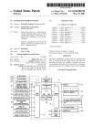
CARBURETOR MODEL 1904 TABLE OF CONTENTS DESCRIPTION PAGE
1. DESIGN
2. APPLICATION 3. MAJOR SUBASSEMBLIES
OPERATION 1. FUEL INLET SYSTEM
2. MAIN WELL AND ECONOMIZER BODY 3. MAIN METERING SYSTEM 4. IDLE SYSTEM 5. POWER ENRICHMENT SYSTEM
6. ACCELERATING PUMP SYSTEM 7. CHOKE SYSTEM
8. DASHPOT OVERHAUL 1. INTRODUCTION 2. SPECIAL TOOLS AND IMPROVISED TOOLS
3. MASTER REP AIR KITS 4. DISASSEMBLY A. Preparation B. Disassembly-Main Body Assembly from Throttle Body Assembly
C. Disassembly-Main Body Assembly D. Disassembly-Throttle Body Assembly 5. CLEANING AND INSPECTION A. Cleaning B. Inspection 6. REASSEMBLY A. Reassembly-Throttle Body B. Reassembly-Main Body C. Reassembly-Main Body to Throttle Body Assembly
INSTALLATION 1. INSTALLATION ON THE ENGINE 2. CARBURETOR ADJUSTMENTS A. Adjnsting the Idle B. Adjnsting the Dashpot 1
2
2
3
4
5
6
6
7
8
8
9
10 10 10 10 10 12 17 17 17 18 18 18 19 22 22 22 22 22 ~ ~ ~
1 of 1 7/30/20099:42 PM
Donated by John & Susan Hansen - For Personal Use Only
MCarbHollIHC53E322B . page 2 of 25
I~ ~
2 of 25
~ ~I
[8!i!iiiI
http://www.oldcarmanualproject.com/manuals/Carbs/Holley/H...
12 Q .4: fHi 18 .a 10 1112
)
INTRODUCTION
The Holley Carburetor Model 1904 is a notable advance in carburetion engineering. It combines the time-proved
Holley characteristics of efficiency, dependability, and effective performance in a compact unit of outstanding
simplicity.
The elimination of the conventional air horn has resulted in a carburetor less than two thirds the height, but having
a capacity comparable to units of standard design. By locating the choke plate in the venturi, the elimination of the
air horn has been accomplished with no loss in efficiency or performance. In addition, the arrangement of the
mixture discharging components in relation to the choke plate when open, aids in the distribution and vaporization
of the fuel discharged into the airstream passing through the venturi.
In line with the advanced engineering conception of this carburetor is the transparent fuel bowl of most versions
of this carburetor model. This transparent fuel bowl greatly simplifies trouble shooting and carburetor servicing.
Overhaul procedure also has been simplified by combining most of the fuel metering elements of the carburetor
in a single, easily replaceable assembly.
Close attention to design details has resulted in the improvement of various other parts. A spring
arrangement is incorporated in the fuel inlet needle to cushion float movement and act as a vibration dampener to
stabilize the fuel level on rough roads. The conventional economizer piston and accelerating pump piston have
been replaced by neoprene diaphragms to insure more positive action and increased service life.
This manual includes a full factory-approved overhaul procedure together with much valuable information
on the description, operation, and adjustment of the Carburetor Model 1904. Careful adherence to the procedures
given in overhauling this carburetor will insure the retention of the high standard of economical, efficient, and
dependable performance, characteristic of all Holley products, which is delivered by this carburetor.
DESCRIPTION
ing lasting, effective, and dependable service.
Most versions of this carburetor model contain a
tempered glass fuel bowl which permits visual inspection
of the float chamber. The action of the float and of the
economizer stem during operation can be readily
observed. Fuel level is clearly visible and the presence of
water or sediment in the float chamber is readily
detected.
Fuel from the carburetor fuel inlet discharges below the
fuel level in the float chamber to prevent foaming or
splashing, assuring a constant, uninterrupted fuel flow to
the metering components of the carburetor. Fuel in the
float chamber circulates completely around the easily
removable main well and economizer body which
contains
most of the fuel metering elements and passages.
HOLLEY CARBURETOR MODEL
This
circulation
has a cooling effect on the fuel being
1904 STANDARD ENGINE
metered through the passages in the main well and
economizer body. In addition to that factor, the high-lift
1. DESIGN
design ofthe carburetor main well gives this carburetor
The Holley C~buretor Model 1~4 is a .single-barrel. excellent hot operation and anti-percolation qualities.
downdraft umt of advanced deSign. ThiS carburetor IS
a model of noteworthy compactness and simplicity
with its many new features assur
Improved control of the power enrichment
r
~ ~ ~
1 of!
7/30/2009 9:44 PM
Donated by John & Susan Hansen - For Personal Use Only
MCarbHolllHC53E322B . page 3 of 25 I~ ~
3 of 25
....I
~
http://www.oldcarmanualproject.com/manuals/Carbs/Holley/H ...
121L1 fBi 1 8 !LW 1112 .l.a )
system is assured by a unique diaphragm-type
economizer. This type of economizer, which may be
removed without disassembling the remainder of the
carburetor, insures accurate response to variations in
engine load conditions.
These new features have been incorporated in this
carburetor in cOrUunction with many of the time-proved
engineering refmements found in other Holley carbureto
models. The carburetor is fully sealed and balanced, wi
all air bleeds and vents being open only to the air cleaner
This filtered air supply gives added protection against th
accumulation of foreign matter in the carburetor passage
The main jet and other fuel metering components are
individually flow tested to insure proper calibration ofth.,1:._ _ _ _ _ _ _ _ _ _ _ _ _ _~~---l
carburetor. Smoother acceleration is assured by the
HOLLEY CARBURETOR MODEL 1904
prolonged discharge of fuel provided by the spring
WITH ALTITUDE ADJUSTMENT
overriding feature of the diaphragm type accelerating
pump. The fully-automatic vacuum-actuated power
enrichment system of improved design provides the
NOTE
enriched mixture required for high power operation.
Carburetor part numbers and other information applicable
to specific I.H.c. vehicles may be obtained from the
current Holley Carburetor Parts Catalog Sheets for these
carburetors.
3. MAJOR SUBASSEMBUES
.......__ .. ,. HOLLEY CARBURETOR MODEL 1904 FOR
AUTOMATIC TRANSMISSION ENGINE
2. APPUCA110N
This carburetor model is used on the International
Harvester Company 220 SD, 240 SD, 269 BD, 282
BD (C. O. E.), and 282 BD truck engines.
This carburetor model is composed of two subassemblies:
the main body assembly and the throttle body assembly.
The die cast main body contains the float and fuel inlet
valve, the fuel bowl, the carburetor air inlet, the venturi,
the choke mechanism, the economizer diaphragm and stem
assembly, the accelerating pump, the main well and
economizer body assembly, the main nozzle, and the pump
discharge nozzle. Included in the main well and
economizer body assembly are a large part ofthe various
fuel metering components and fuel passages of the
carburetor. The cast iron throttle body contains the throttle
plate, the idle discharge ports, the distributor vacuum port,
and the idle speed and mixture adjusting screws.
On the carburetor used with automatic transmission engines, the dash pot assembly is mounted on a boss on the side of the main body. OPERATION
The fuel-air requirements of an automotive engine
vary considerably throughout its range of operation.
To assure effective carburetion, the
carburetor must supply an efficient but economical mixture for normal cruising conditions, a richer mixture when a high power output is desired,
~13.
1 of 1
7/30/20099:45 PM
Donated by John & Susan Hansen - For Personal Use Only
MCarbHollIHC53E322B - page 4 of 25 I~ ~
4 of 25
• •1
Homel
http://www.oldcarmanualproject.comlmanuals/Carbs/Holley/H...
12 J;HHHi 1 fi ~ 101112 13 14
enr:'
•
H,.'ll
N2-41!
FI!f.l
'~·\l 'If
niP
FUEL INLET SYSTEM
enters the carburetor through the fuel inlet needle valve
and a still richer mixture for a smooth idle and low
and seat assembly and flows into the float chamber. The
sp.eed performan~. In order to suppl~ the con:~
float, rising and falling with the fuel level in the float
mixture to the engme under all operatmg conditions,
h b
th fu I' I
dl'
.
.
the Holley Carburetor Model 1904 has four basic fuel c am er, moves e e m et nee em !elation to Its
metering systems. These are the main metering
seat to regulate the amount. of fuel entermg the
system, the idle system, the power enrichment system, carburetor. When the fuel m the float chamber reaches a
and the acceleratmg pump system. In addition, there is specified level, the float moves the needle valve to a
a fuel, inlet system "Yhich provides the four basic fuel position to restrict the flow of fuel. Only enough fuel to
metermg systems Wlt~ a cons?IDt supply of fuel, and replace that being used will then be admitted. Any slight
the. chok~ sy.stem whl~h provld~s ~ mean~ of tempo- change in the fuel level ca ses a corresponding
rardy ennching the mixture to aid m startmg and u .
.
,
running a cold engine. movement of the float, openmg or closmg the fuel mlet
needle valve to inunediately restore the proper fuel
level. The fuel inlet system must constantly maintain
1. RJEL INLET SYSTEM
this s~ecified level of fu~l because th~ basic fuel
metermg systems are cahbrated to dehver the proper
The fuel inlet system provides the four basic fuel mixtures when the fuel is at the specified level only.
metering systems and the choke system of the
carburetor with a constant supply of fuel. This fuel,
under pressure from the engine's fuel pump,
A spring and pin inside the hollow fuel inlet
~ ~.
lofl 7/30/2009 9:45 PM
Donated by John & Susan Hansen - For Personal Use Only
MCarbHolllHC53E322B . page 5 of 25
I..
5 of 25
1IHomel
••
http://www.oldcarmanualproject.com/manuals/Carbs/Holley/H. ..
1415
12Q:tQ218a 10
needle valve cushion the needle valve for protection
against road shocks and vibration. A fuel valve clip,
attached to the bottom of the needle valve, fits under
the tab of the float lever to insure proper response of
the needle when the float drops.
P"~'AC:
•
o'~~,
D'" 11m )Y~Tf""
,.-;::-.,
.. 0
'''''IJ
~
A balance tube in the air inlet of the carburetor
bore vents the float chamber to maintain balanced air
pressures in that chamber, assuring proper fuel
metering in all phases of engine operation.
':UWt
MAIN Mr.TIY.ING
r..,Y")':-:M
'o.... t, t,.,,~;,.:t1,
""[I, T SYSTeM
I!irIll11 "'(";("l~[~"',l NO
IllWUl.Jl r I.J "'F' ',Y 5 T( M
O
.AIR ~.\.~D;
A"l:> V;:~',
2. MAIN WELL AND ECONOMIZER BODY Fuel in the float chamber is distributed to the
fuel passages of the four basic fuel metering systems
through the main well and economizer body. A study
of the passages in this assembly will insure a clearer
understanding of the explanation of the operation of
the four fuel metering systems.
MAIN
10""'11
MAIN WELL AND ECONOMIZER
N~Ulf
.'M h ····LI.~
~
'1
,1
\
<ODt
•
[~
_
AIR
-J
FLH
fUt~-"'IM W.llC'lJl(t
k'·113
....l\II'l"'[ll
MAIN METERING SYSTEM
.~.
1 of 1
7/30/20099:46 PM
Donated by John & Susan Hansen - For Personal Use Only
MCarbHollIHC53E322B - page 6 of 25
I..
6 of 25
....,
IHomel
http://www.oldcarmanualproject.com/manuals/CarbsiHolley/H ...
12.a.4Qfi18~
10
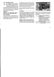
3. MAIN METERING SYSTEM
When the engine is running, the intake stroke of each
piston draws air through the carburetor. As this air
passes through the venturi of the carburetor, the drop
in pressure in the venturi creates what is commonly
called a vacuum. The strength of that vacuum varies in
proportion to the velocity of the air flow through the
venturi. This, in tum, is governed by the speed and
power output ofthe engine.
At normal cruising speeds, the difference between the
normal, atmospheric air pressure in the float chamber
and the vacuum in the venturi is used to operate the
main metering system. This pressure differential draws
a metered flow of fuel from the float chamber through
the main metering system and out the main nozzle into
the air stream in the venturi. When the fuel passes out
of the float chamber, it is metered (or measured) by the
main jet as it flows into the bottom of the main well.
The fuel moves up the main well past the two
narrow air bleed passages and enters the main nozzle.
Filtered air from the carburetor air inlet enters the air
.",
~on;,.
_
.. JH
_
>jri~An' 5~\P:11J~:
fl}t
~
>"(;, ;l.M
16
speed bleed and passing out the two narrow air
bleed passages is mixed with the fuel flow in the
main well. The high speed bleed meters a properly
increasing amount of air into the fuel as speeds
increase, stabilizing the fuel discharge and main
taining the required mixture ratios. This emulsion of
fuel and air, being lighter than the raw fue~ has a
more instantaneous response to any change in
venturi vacuum and is more readily vaporized than
raw fuel upon being discharged into the air stream.
The fuel flows through the main nozzle and is
sprayed onto the open choke plate in the venturi.
Airstream turbulence over the distribution pin and
choke plate distributes the fuel over the lower
portion of the choke plate where it is vaporized and
mixed with the air flowing through the carburetor.
The throttle plate controls the amount of fuel-air
mixture admitted to the intake manifold, regulating
the engine speed and power output in accordance
with accelerator pedal movement. The distribution
pin extending perpendicularly from both sides of the
choke plate creates a turbulence as an aid to the
proper distribution ofthe mixture to all cylinders of
F4~'>..\CE~
')
~A1HWf::i
tnt
t: I ....:.,!... \ ..t:.. H(!I}\
;;;:-.:..1.;
IDLESYS1EM
.8 ..
10fl
7/30/2009 9:46 PM
Donated by John & Susan Hansen - For Personal Use Only
MCarbHollIHC53E322B - page 7 of 25
I~ ~
7 of 25
.... I
IHomel
http://www.oldcarmanualproject.com/manuals/Carbs/Holley/H-..
12 Q .4di fi 1 a ~ 10 11 12 13
;\t the idle and low speeds,. the velocity of the air
flowmg through the carburetor IS reduced and the
vacuum created in the venturi will not be strong enough
to operate the main metering system. Because of the
restriction of the air flow through the carburetor due to
the nearly closed throttle plate, intake manifold vacuum
will be high. This high manifold vacuum provides a
pressure differential which is used to operate the idle
system.
1617
smooth, even transition from idle to cruisin
S.
d
g spee s.
PO~ER ENRICHM ENT SYSTEM
When high power output is required, a richer mixture must be
prov~ded than is required for normal cruising when no great
load IS pl~ed on the engine. The carburetor provides the added
fuel for high power operation by means of the power
enrichment system, sometimes called the economizer system.
At the idle, fuel flows through the main jet into the
The power enrichment system is actuated by manifold
bottom of the main well. The high manifold vacuum
acting on this fuel through the idle system passages
vacuum. Manifold vacuum, which is strongest at the idle
draws the fuel from the main well through a short
when there is no load on the engine, is reduced in proportion
horizontal passage into the idle well. A calibrated
to the increase in engine loading. This is due to the fact that,
restriction in the lower portion of the idle well meters the as the load on the engine is increased, the throttle plate must
flow of fuel entering the idle system. The fuel passes out be opened wider to maintain any given speed. Manifold
the top of the idle well and into the idle system passages vacuum will be reduced because the restriction offered to
in the main body. A metered flow of air from the idle air the air flow entering the intake manifold by the throttle plate
bleed is admitted to the fuel as it enters the idle passage will be lessened as the plate is opened. The strength ofthe
in the main body. The idle air bleed also serves to vent manifold vacuum is thus an accurate indicator of the power
the idle system to prevent any siphoning effect at higher demands placed on the engine..
speeds or when the engine is stopped. This mixture of
fuel and air continues down, flowing through the idle
.
.
.
.
restriction and, passing the two idle transfer holes in the
Matufold vacuuI? actmg on the eco~omJzer dIaphragm
throttle body, is discharged through the idle discharge
actuates th~ power ennchment system. ThiS vacuum from, the
hole into the strong manifold vacuum existing below the lower portion of the throttle bore below the throttle plate IS
throttle plate. The two idle transfer holes act as additional transmitted through the vacuum passage to the vacuum chamber
air bleeds at the idle. An idle adjusting needle, which
on !o.p of the economizer diaph~agm, At idle and n.onnal
.
seats in the idle discharge hole, controls the discharge of c:Ulsmg sp~eds, the vacuum actmg on th~ economizer
fuel at the idle and provides a means for adjusting the
diaphr~ IS stron~ enough to h~ld the ~1ap?ragm up agaills~
idle mixture of the engine. Turning the idle adjusting
~e tenSIOn of the diaphragm. sprmg. ThiS rruses the economizer
needle in moves the pointed tip of the needle closer to its dl~phragm s~m clear of the t:~wer valve and.the po:ver v~lve
seat, restricting the fuel flow out of the idle discharge
wlll be held ill ~e closed POSItiO~ by the te~slOn of.lts ~prmg.
hole. This results in a leaner idle mixture. Conversely,
The power enrIchment system wtll thus be moperatIve m
turning the needle out allows more fuel to flow out the conditions of high manifold vacuum.
idle discharge hole to provide a richer idle mixture.
During off-idle operation, which occurs when the throttle
plate is moved open slightly past the two idle transfer
holes, each hole begins discharging fuel as it is exposed to
manifold vacuum. As the throttle plate is opened still
wider and engine speed increases, the velocity of the air
flow through the carburetor is also increased. This creates
a vacuum in the venturi strong enough to bring the main
metering sYstem into operation. The flow from the idle
system tapers off as the main metering system begins
discharging fuel. The two sYstems are engineered to
provide a
When high power demands place a greater load on the engine,
manifold vacuum is reduced. When the vacuum is reduced
below a predetermined point, the diaphragm can no longer
overcome the tension of the diaphragm spring and the stem
will be forced down. This depresses the pin in the center of
the power valve, opening the valve. Fuel from the float
chamber will flow into the valve and, passing through a
horizontal passage, enter the main well. There it is added to
the fuel flow of the main metering system, enriching the
mixture for full power. The drilled plug in the passage
between the power valve and the main well is a calibrated
restriction which meters the flow of fuel through the power
enrichment system.
~
1 of!
[3 ..
7/3012009 9:47 PM
Donated by John & Susan Hansen - For Personal Use Only
MCarbHollIHC53E322B . page 8 of 25
I~ ~
8 of 25
~ ~I
http://www.oldcarmanualproject.com/manualslCarbs/Holley/H. ..
12 Q1, li .61.8. ~ 10
IHomll1
12 13 14 15 16
_n.LL
(cor
_
MANlfOLJ V)\C1..,l."i
Vb.ClJUM
I'A;5AG~
rt, .
.t t~
POWER ENRICHMENT SYSTEM
6, ACCELERATING PUMP SYSTEM
provided by the pump spring assures an even, prolonged
discharge of fuel regardless of how suddenly the throttle
The air flowing through the carburetor responds ahnost is opened and cushions the action of the pump to prevent
immediately to any increase in throttle opening. There is,
damage to the pump linkage due to those sudden throttle
however, a brief interval before the relatively heavier fuel-air movements.
mixture in the narrow carburetor passages can gain speed and
,
maintain the desired balance of fuel and air. The accelerating The fuel, under pres.sure from the dIaphragm, .flows
pump system operates during this interval, supplying fuel untithrough.the pump dIscharge passage and: forcmg the
the other systems can provide the proper mixture.
pump dIscharge ball check valve and weIght up, passes
into the pump discharge nozzle screw. The pump
When the throttle is closed, the pump return spring forces the discharge ball check valve seals the passage when the
pump is not discharging fuel. The hexagonal weight holds
pump diaphragm toward the back of the pump chamber,
drawing fuel into the chamber through the pump inlet. The the ball check valve on its seat to prevent a loss of fuel
pump inlet contains a baU check valve which opens to admit from the pump chamber due to the siphoning effect of the
fuel from the float chamber into the pump chamber, and clos~rstream at high engine speeds.
when the pump is operated to prevent a reverse flow of fuel.
Flowing up the hollow pump discharge nozzle screw, the
fuel passes out holes in the head of the screw into the
When the throttle is opened, the movement is transmitted by pump discharge nozzle and is sprayed into the airstream
the pump link to the pump operating lever. That lever presses in the venturi. A slot cut into the pump discharge nozzle
the pump rod sleeve inward, compressing the pump spring, vents the system to prevent the pump discharge baU check
The pump spring, in turn, presses on the diaphragm, forcing valve and weight from being lifted and fuel drawn from
the fuel from the pump chamber into the pump discharge
the pump chamber by the siphoning tendencies of the
passage. The "overriding" feature
airstream at high engine speeds.
~~~
1 of!
7/30/2009 9:48 PM
Donated by John & Susan Hansen - For Personal Use Only
MCarbHollIHC53E322B - page 90f25
I~ ~
9 of 25
~ ~I
[Home I
http://www.oldcarmanualproject.com/manualslCarbs/Holley/H ...
123.1dHi1B.9.10 1112 13 H
16171819
tOUk
.~'_tL
1l2·"h!
ACCELERATING PUMP SYSTEM
7. CHOKE SYSTEM
n a coldengine, much of the vaporized fuel from the
:arburetor condenses to a liquid on contact with the low
lressure area and cold surfaces of the intake manifold. This
-esults in an inefficient distribution of fuel to the cylinders,
:ausing hard starting, rough running, stalling, and loss of
lower. The choke plate is the means used to provide an
:nriched flow of fuel to aid in starting and warming-up a
:old engine. Closing the choke plate which is located in the
rentur~ confines manifold vacuum within the carburetor
md draws a rich flow of fuel from the idle and main
netering systems. When the engine starts, enough air is
lrawn through the spring-loaded poppet valve in the choke
llate to enable the engine to run and to prevent flooding.
rhe throttle plate opening is increased by the fast idle cam
luring choking to allow the engine to operate at a mst idle
o prevent stalling. The fast idle cam, which is a curved
:xtension of the choke lever, contacts the throttle stop screw
md prevents the throttle plate from closing completely
'{hen the engine is choked.
8. DASH POT
Engines equipped with automatic transmissions require
an anti-stall device as protection against loading the
engine when the accelerator pedal is suddenly depressed
and released. This protection is provided by the dashpot.
The dashpot retards the closing rate of the throttle plate
as it approaches the idle position, allowing the engine to
dissipate the raw fuel discharged into the intake manifold
by the accelerating pump.
The dashpot slows the final phases ofthrottle plate
closing by means of a spring-loaded diaphragm. When
the accelerator pedal is released, the throttle return spring
in the throttle linkage closes the throttle plate
simultaneously with the release of the pedal. As the
throttle plate approaches the idle position, a tab on the
throttle lever contacts the lower edge of the dashpot
lever. This rotates the dash pot lever, causing the head of
the dashpot adjusting screw of the dashpot lever
~13~
1 of 1
7/30/2009 9:48 PM
Donated by John & Susan Hansen - For Personal Use Only
MCarbHoIlIHC53E322B· page 10 of 25
I..
10 of 25
••1
IHomel
http://www.oldcarmanualproject.com/manualsiCarbs/Holley/H ...
12.3.1 Q fi 1 aft 10 1112 13 14 15 16
18 19 20
DASHPOT·(AUTOMATIC TRANSMISSION)
to impinge on the dashpot diaphragm rod. As the rod
is moved into the dashpot, the tapered step of the rod
engages the diaphragm washer. Continued movement
of the rod will cause a corresponding movement of
the diaphragm, compressing the air in the diaphragm
chamber above the diaphragm. The compressed air
bleeds out of the diaphragm chamber through a
groove in the seat of the diaphragm washer, retarding
the closing speed of the throttle plate. This allows the
engine to properly use the charge of accelerating fuel,
preventing
stalling from an over-rich condition in the manifold.
When the throttle is again opened, the pressure is
released from the dashpot diaphragm rod and the
dashpot return spring moves the rod off its seat in the
diaphragm washer. This allows air to flow back into
the diaphragm chamber. After moving the rod off its
seat, the spring returns the rod and diaphragm to their
original position.
OVERHAUL 1. INTRODUCTION
The proper overhaul of the carburetor requires
that it is completely disassembled and each part is
thoroughly cleaned. Each clean part should then be
examined for signs of wear, damage, or deterioration.
Defective parts should be
replaced with genuine Holley replacement parts aud
the carburetor should be carefully rebuilt. Care in
rebuilding and accuracy in adjusting the carburetor
will insure the continuation of the characteristics of
power, economy, and performance engineered into
every Holley carburetor.
• IB • lofl
7/30/2009 9:49 PM
Donated by John & Susan Hansen - For Personal Use Only
MCarbHollIHC53E322B . page 11 of 25
I~ ~
11 of 25
~ ~I
IHome I
http://www.oldcarmanualproject.com/manuals/Carbs/Holley/H...
12.3..4 Ii.61 ~U! 10 1112 13 14 15 16 17 18 19 20 21
2. SPECIAL TOOLS AND IMPROVISED TOOLS
This carburetor may be overhauled using ordinary tools if a reasonable amount of care is exercised. Overhaul will
be facilitated, however, and damage to parts avoided if factory-approved tools are used. The special tools
recommended for use in the overhaul of this carburetor are listed below.
TOOL
Main Jet Wrench
Power Valve Wrench
(Used for fuel inlet seat retainer screw)
Float Gauge
SNAP-ON
TOOL NO.
TMC-36
MC-128
HOLLEY
TOOL
82R-49
82R-34
MC-I64
[n addition to the special tools listed above, a simple tool
for removing or installing the distribution pin may be
mprovised. Obtain a section of brass tubing at least three
nches long with an inside diameter of 118 inch (or slightly
.arger if that size is not 0 btainab Ie), a length 0 f 118 inch or
.arger drill ro d (or a flat-tip punch having an end diameter
)f a least 118 inch), and a length of No.
52 or 1/16 inch diameter drill rod. "These improvised
:ools are to be used as described in the overhaul
3rocedure that follows.
82R-53
,.,;.;;
f-".
PART NAME
,,'"
"'"
""t'
2
3
1
2
3
Pump Link Cotter Pin
Throttle Body Screws and
Lockwashers (2)
Throttle Body Gasket
3. MASTER REPAIR KITS
The Master Repair Kits contain Holley replacements
for parts which are subject to wear or may be
iamaged in disassembly. The disassembly procedure
neludes instructions to discard all parts for which
:eplacements are provided in the Master Repair Kit.
The proper kit for this carburetor is listed in the
:urrent Holley Carburetor Parts Catalog Sheets for
;bese carburetors.
4. DISASSEMBLY
A. PREPARAnON
--.~;: '':~'''''''.-'
c..-=~.::;;:::.~<_:>_3
During disassembly, use separate containers for the
component parts of both major subassemblies; the
main body assembly, and the throttle body assembly.
Cleaning, inspection, and reassembly will be
facilitated by use of separate containers.
,\"l
B. DISASSEMBLY-MAIN BODY ASSEMBLY
FROM THROTILE BODY ASSEMBLY
~;Jn
The following list contains all parts removed in
separating the main body assembly from the throttle
body assembly.
Parts to be discarded
and replaced from a Master Repair Kit are marked
with an asterisk (*).
1',/8
N~--II~
Figure I. Disassembly - Two Maier Subassemblies
-10
~ ~ ~
10fl
7/30/20099:49 PM Donated by John & Susan Hansen - For Personal Use Only
MCarbHolllHC53E322B . page 12 of 25 I~ ~
~ ~I
12 of 25
IHomel
http://www.oldcarmanualproject.com/manuals/Carbs/Holley/H ...
2 ~.1 Q!i 1 ~ ~ 10
12 13 14 15 16 17 18 1920
\\
'\,
'\
\\
\
\\
'..J.
'MIt::,-r
~()~.
I
!
+
'*=
1{.1-l:II}
figure 2. Removing Pump Link Cotter Pi.,
~."-"".:J
Figure 3. RemovIng Throttle BodY
!.~ .... w.
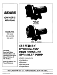
(2) Remove the two throttle body screws and
lockwashers. Separate the throttle body and main
body and discard the throttle body gasket.
(1) Remove and discard the upper pump link cotter
pin. Disengage the upper end of the pump link from
the pump operating lever.
:17
IV!_
39......
yll I
17
I, I
··,t....:J,.:J4I
~
~5~_~ . .
4(,-c:..~
41
,
\ 4'l~.
fY~
~'-.- ~ I
.
,
43--
IA
'
1
\I I;
15
1
'
L r;;;<-J
'~rf.f~~;01
~
~'ill~
Il'l~~~j
~.-.. I b~ ..I~" rJ,f.:r7
~/ ~.'
,(
\
10
\
j
'f
I
~
T
~'., ,~"J
"'"
\
.' .:__ 11
Ii?
..
'-~..lR'li:
_-~!r
3
~](.
.~
,};;..
~
,
2
~':!5
::n/
~
l
. ~-~
~: ~,
1/ ~l
~tl'a:~:/..
~.J~.
" .e'~
n
H
'?B
1.1
A
la~"
. IA
t\
•
i~~~~~ /r
~
-:
\
~'S:
~.~
,\
40 .......,·;· .Q;)'-.
.u ---_(:~i .
16
H
,-...,.-. \
."'
.
{
"
\
,.
\
AUlo"".... rl( HiII\i~MI~~ION
V,KDUKHOK PA,{ b
I
,
.1,
.JI 1",1.
",4Ii
~ J
\!f~'
R3-421A
FIGURE 4. DISASSEMBLY - MAIN BODY ASSEMBLY
~
1 of 1
13
~
7/30/20099:49 PM
Donated by John & Susan Hansen - For Personal Use Only
MCarbHollIHC53E322B . page 13 of 25
I~ ~
13 of 25
~ ~I
IHomel
http://www.oldcarmanualproject.com/manualslCarbs/Holley/H ...
Q:U!21~.l! 10111213
c. DISASSEMBLY-MAIN BODY
in disassembling the main body assembly. Parts to be
discarded and replaced from a Master Repair Kit are
marked with an asterisk (*).
PART NAMe:
PART NAME
5
5
11A
lB
6
2
6
3
6
4
6
6
7
7
8
9
9
10
5
9
11
9
12
9
9
9
14
15
10
16
11
17
18
11
13
19
12 20
14 21
22
14 23
13
Dashpot Assembly
Dashpot Lockwasher
Clamp Ring Retainer Screw and
Lockwasher (4)
Clamp (4)
Clamp Ring
Clamp Ring Gasket *
Fuel Bowl
Fuel Bowl Gasket *
Fuel Inlet Seat Retainer Screw *
Fuel Inlet Seat Retainer Screw
Gasket *
Fuel Inlet Seat Gasket *
Float Shaft Retainer *
Float Shaft *
Fuel Inlet Needle Assembly *
Float and Lever Assembly
Fuel Inlet Valve Seat *
Economizer Body Cover Screw
and Lockwasher (4)
Economizer Body Cover
Economizer Diaphragm and Stem
Assembly *
Economizer Body Cover Gasket *
Main Well and Economizer Body
Screw and Lockwasher (5)
Main Well and Economizer Body
Pump Return Spring
Main Jet
16 17 18 19202122
15
15
16
16
24
25
26
27
16 28
17 29
17 30
18 31
18 32
18 33
19 34
20 35
21 36
22 37
23 38
23 39
23 40
24
25
25
26
41
42
43
44
45
26 46
47
Pump Inlet Check Valve Retainer
Pump Discharge Valve Retainer
Pump Discharge Valve Weight
Pump Discharge Valve Ball
Pump Inlet Valve Ball
Spacer Gasket
Pump Diaphragm and Rod
Assembly'"
Pump Rod Sleeve Retainer Ball
Pump Rod Sleeve
Pump Spring
Pump Operating Lever Retainer
Pump Operating Lever
Choke Bracket Screw and
Lockwasher
Distribution Pin
Choke Plate Screw
Choke Plate Screw and
Lockwasher
Choke Plate
Choke Shaft Retainer Pin
Choke Shaft and Lever Assembly
Choke Bracket
Pump Discharge Nozzle Screw
Pump Discharge Nozzle Screw
Gasket
Pump Discharge Nozzle
Pump Discharge Nozzle Gasket
(
Figure 6. Removing Clamp Ring Retainer Screws
Figure 5. Removing Dashpot Assembly
(1) If the carburetor being disassembled is for an
automatic transmission engine, remove dashpot
assembly and dashpot lockwasher.
(2) Remove the fuel bowl by removing the four
clamp ring retainer screws and lockwashers, and
clamps. Lift the clamp ring off the fuel bowl.
Remove and discard the fuel bowl gasket and the
paper clamp ring gasket
~~~
10fl
7/30/20099:50 PM
Donated by John & Susan Hansen - For Personal Use Only
MCarbHollIHC53E322B· page 14 of 25
I~ ~
14 of 25
~ ~I
IHomel
http://www.oldcarmanualproject.com/manuals/Carbs/Holley/H...
1: Q21 6.!! 10 1112 13 14
16 17 18 19 20
23
(5) Remove the float shaft retainer and separate the
float and lever assembly from the fuel valve
assembly by sliding out the float shaft. Discard all
parts except the float and lever assembly.
Agure 7. Removing Fuel Inlet Seat Retainer Screw
(3) Using Snap-On Tool No. NfC-128, remove
the fuel inlet seat retainer screw. Discard the retainer
screw and gasket.
Figure 10. Removing Economizer Body Cover
(6) Remove the three economizer body cover screws
and lockwashers.
(7) Lift the economizer assembly out of the main
body and discard the gasket.
Rgure 8. Aoat and Fuel Inlet Valve Assembly
(4) Lift out the float and fuel inlet assembly and
discard the gasket.
"JtL
II'oIL~f
"4·19
Rgure 11. Removing Economizer Body
~HAr~
~t'AINER
U
FLO"y
R!!''';J4
Rgure 9. Float and Fuel Inlet Valve Separated
(8) Separate the economizer body cover from
the economizer diaphragm and stem assembly.
Discard the economizer diaphragm and stem
assembly.
~8~
1 of!
7/30/2009 9:50 PM
Donated by John & Susan Hansen - For Personal Use Only
MCarbHollIHC53E322B - page 15 of 25
I~ ~
15 of 25
~ ~I
IHomel
http://www.oldcarmanualproject.com/manuals/Carbs/Holley/H...
!H!.7 §. ~ 10 1112 13 14 15 16 17 18 19 20
23
(11) Using Snap-On Tool No. TMC-36, remove the
main jet from the main well and economizer body.
Discard the main jet.
Figure 12. Removing Main Well and Economizer Body Screws (9) Remove the five main well and economizer
body screws and lockwashers. (Place a thumb against
the main well and economizer body to retain it in
position until those screws and lockwashers have
been removed.) Lift out the main well and
economizer body.
Figure 15. Removing Pump Valve Retainers
(12) Remove the pump inlet check valve retainer
and the pump discharge valve retainer.
Figure 13. Removing Pump Retum
(10) Remove the pump return spring which bears
against the metal disk of the accelerating pump
pIston.
Figure 16. Removing Pump Inlet and Discharge Valve Balls and Weight (13) Invert the main well and economizer body and allow the
pump inlet check valve ball, pump dischar~lve weight, and
pump discharge valve ball to drop out. Discard the two steel
balls.
I"
,...,..,
Figure 17. Removing Accelerating Pump Assembly
Figure 14. Removing Main Jet
(14) Slide the accelerating pump assembly out ofthe
main body. Remove and discard the spacer gasket.
~[3~
1 of!
7/30/20099:51 PM
Donated by John & Susan Hansen - For Personal Use Only
MCarbHoillHC53E322B - page 16 of 25
I~ ~
http://www.oldcarmanualproject.com/manuals/Carbs/Holley/H...
12 13 14 15 16
••1 IHomeI
16 of 25
CAUTION
18 19 20 21
23
(18) Slide the pump operating lever off the stud.
Care must be taken when removing the
accelerating pump assembly as the pump rod
sleeve is under considerable spring tel\Slon.
The assembly must be pulled straight out and
not rotated during removal.
.• ,ii<~
..)::1~!;--·~
_,~~\st
"
Figure 21. Removing Choke Bracket Screw
(>
I ;,.;:.
Figvr" la. Remov illll P\JIl1f' Rod SIAIWII! ~I!IMrne-r Boll
(19) Remove the choke bracket screw and lockwasher. (15) Press the pump rod sleeve toward the
pump diaphragm, compressing the pump spring; and
allow the pump rod sleeve retainer ball to drop out
(rotate the sleeve if the ball sticks in place). Discard
the ball.
()l'iolklBUilON
PIN
(16) Slide the pump rod sleeve and pump
spring off the pump diaphragm rod. Discard the pump
diaphragm and rod assembly.
+-
BRA,i':;JU
... JI
Figure 22. Removing Distribution Pin
Figure 19. Rem;)virlg PllIIF Operating LI\Vf!f" Retoi.... cr
(17) Using the thin·bladed screwdriver, pry the
pump operating lever retainer off the pump operating
lever stud. Discard the retainer.
(20) Rotate the choke plate past the full open
position until it is nearly inverted. Place the
distribution pin in a section of brass tubing with the
end of the tube bearing against the choke shaft. Using
a flat tip punch or a piece of 118 inch drill rod, drive
the pin flush with the choke shaft. Then, using a
smaller diameter punch or drill rod, drive the pin out
of the choke shaft. Refer to "Special Tools and
Improvised Tools" on page 10 for complete
information on the improvised tools.
NOT
In the illustration (Figure 22), a section of the
upper portion of the brass tubing is shown
cutaway for the purpose of clarity. Do not cut
out this section of tubing.
Figure 20. Removing Pump Operating Lever
~
1 of 1
[3 •
7/30/20099:51 PM
Donated by John & Susan Hansen - For Personal Use Only
MCarbHollIHC53E322B - page 17 of 25
I..
17 of 25
••1 IHomel
http://www.oldcarmanualproject.com/manuals/Carbs/Holley/H...
1.6. f!
10 l i 12 13 14
18192021
CAUTION
Care is to be taken when removing the dis
tribution pin to prevent damaging the choke
shaft and poppet valve.
Figure 25. Removing Choke Shaft
(23) Remove the choke shaft and lever assembly
and the choke bracket.
Figure 23. Removing Choke Plate
(21) Remove and discard the choke plate screws
ld locwasher and slide the choke plate out of the
loke shaft.
NOT
{.,--so";
lfthe tip of the choke plate screw has been flared out excessively by staking, it is ad
visable to file off the flared-out portion to avoid damaging the threads in ilie choke when removing the screw. Care is to be taken while filing the screw tip to avoid damaging the carburetor bore, choke shaft, or other components. ""~'i'
~f'
... :-- ,\ f " ~." I
!
t
Figure 26. Removing Pump Discharge Nozzle Screw
(24) Remove the pump discharge nozzle screw
and hft out the pump discharge nozzle. Discard the
two gaskets.
NOT
In some versions of this carburetor model the
fuel bowl contains an externally adjusted
needle for regulating fuel flow through the
main jet. Replacements for this main
adjusting needle assembly will be found in
the Master Repair Kit.
"
! ,~
. ir .
( .' ....
~'ji'j. ;•.....r
.'
"~,"r""'~
-- ,.. !... ~
~<
figure 74. RelTlOving Cho~e S,~h Retainer Pi"
U~tl;l
(22) Using a small flat-tip punch, drive the
hoke shaft retainer pin out of the main bo dv.
~
>
Figure 27. Disassembly" Throttle Body Assembly
.~.
10fl
7/3012009 9:52 PM
Donated by John & Susan Hansen - For Personal Use Only
MCarbHollIHC53E322B . page 18 of 25
I..
..1
18 of 25
IHOfII8I
http://www.oldcarmanualproject.com/manuals/Carbs/Holley/H...
~
fll0 1112 13 14 15 16 17 18 19 20 21 22
This completes the disassembly of the main body
assembly. Do not attempt to remove any of the
pressed-in passage plugs, air bleed plugs, or the main
nome in the main body,
"1';1;
((L I{ D. DlSASSEMBLY-THROITLEBODY ASSEMBLY I
I
.... -.:
The following list contains all parts removed in
disassembling the throttle body assembly. Parts to be
discarded and replacement made from
a Master Repair Kit are marked with an asterisk (*).
REFER TO
ORDER OF
REMOVAl
FIG. NO.
' \..
(;]: .? "'.
tll ".,
,''''.,p.
~
'."'.
"
Figure 29. Pump Link and Cotter Pin
PART NAME
flii(jtH.t
28
28
I
29
29
I
1
2
3
4
30
I
30
30
31
31
6
7
8
9
31
10
~ntP"lf!i
?---
.
l1!110nIL f ... ,£
.
"r '
: I
~.• ~33\~.~~
Lockwasher (2)*
Throttle Plate
Throttle Shaft
Dashpot Lever Screw
Dashoot Lever Soring
Dashpot Lever
.':
" ", r":'~:r'.';,~~r~~~N;: _~I'
~~~ .
~
I iJmo
Link*
TJ ITottle Plate Screw and
,
.. n
~:
Idle Adjusting Needle* Idle Adiusting Needle Soring Pump Link Cotter Pin* I
~
.
figure 30, Tl,roHI.. ShelF! n"d Plate Removud
(4) Slide the throttle shaft and lever assembly
out of the throttle body.
DASHPOTLE~
D.oSHfCJ L[V[~ ~tln,(, . \
.... ,",
"",."J
-.".
~
"~~
tJPOT U'If"
5e11£....,
.___'" ,.,~!r:pf ~r.)~\\LH"':;
..;,JJJjJ
........... ~
...,-./'
,m;:>u
Figure 31, Rerroving Dashpot Lever Screw
DVADUII-.O Nf:H~!;:-
:PRI...,,:::
Figure 28, Rerroving Idle Adjusting Needle
(5) On carburetors for the automatic trans
mission engine, remove the dashpot lever screw,
spring, analever.
(1) Remove the idle adjusting needle and
spring. Discard the needle.
This concludes the disassembly of the Car
buretor Model 1904. (2) Remove and discard the pump link cotter
pin and pump link.
(3) Scribe the throttle plate along one side of
the throttle shaft to facilitate proper alignment during
reassembly. Remove and discard the two throttle plate
screws and lockwashers. Lift out the throttle plate .
5. CLEANING AND INSPECTION
A.CLEANING
( 1)
All castings and metal parts except the
dashpot assembly are to be soaked in a cleaning
• 13. 1 of!
7/30/20099:52 PM
Donated by John & Susan Hansen - For Personal Use Only
MCarbHollIHC53E322B . page 19 of 25
I~ ~
19 of 25
....,
IHomal
http://www.oldcarmanualproject.com/manualslCarbslHolley/H...
12 13 14 15 16 17 18 19 20
solution to loosen the accumulated foreign matter.
Laquer thinner or denatured alcohol may be used if a
commercial carburetor cleaning solvent IS not
available. Place the parts to be cleaned in a wire
basket suspended in the solution. After the parts have
soaked sufficiently to loosen the foreign deposits,
they should be rinsed in hot water to remove all traces
ofthe cleaning solution. All remaining foreigll
deposits should be scrubbed away with a stiff bristle
brush while the parts are being rinsed.
(2) Soak each casting and part briefly in clean
gasoline and dry them with compressed air. Direct the
compressed air through ail passages in the castings
and through all openin~,' jets, and tubes. As the
neoprene i:liaphragm oftne dashpot assembly is
deteriorated by most cleaning solvents, the exterior of
the dashpot assembly should be wiped clean with a
rag moistened with gasoline. Do not use compressed
air on this assembly as the diaphragm and the
synthetic rubber bellows seai may be distorted or
ruptured.
CAUTION
Attempts to clean passages with a wire, drill,
or similar object may distort those passages
and adversely affect carburetor performance.
Use of a buffmg wheel, wire brush, or other
abrasive means to remove surface deposits
may damage the part and also remove the
protective plating, exposing the part to
corrosion.
NOTE
As gaskets, neoprene diaphragms, and felt
seals are deteriorated by most solvents, those
items should never be exposed to cleaning
fluids. Never re-use old gaskets neoprene
diaphragms, or felt seals when rebuIlding the
carburetor.
B. INSPECTION
(1) MAJOR CASTINGS
All major castings are to be examined for
cracks, stripped threads, or damaged gasket mating
surfaces and discarded if damage is found. Check the
venturi bore in the main body casting for si~s of
nicks, scratches, or other imperfections. CalIbration
of the carburetor may be affected by even a slight
irregularity in the venturi. Examine the main
discharge nozzle in the venturi and other passages in
the castings for signs of damage or obstruction. The
check for obstruc
tion may be made by directing compressed air
through the passages. (Refer to the "Operation"
section, begirming on page 2, for locations of pass
ages in the castings).
(2) CHOKE SHAFT AND THROTTLE SHAFT
Check the shafts for distortion, stripped
threads, or loose levers. If irregularities are found, the
shaft should be discarded. Also examine the swivel
assembly on the choke lever for stripped threads. If
damage is found or the swivel is no longer securely
riveted, the choke shaft and lever assembly must be
replaced.
(3) FUEL BOWL
The fuel bowl must be replaced ifthe edges
are chipped or if cracks are found anywhere in the
bowl. In the plastic fuel bowls containing the
adjustable jet, the adjusting needle body must be
checked for signs ofleaking or for other evidence of
damage or distortion.
(4) FLOAT AND LEVER ASSEMBLY
Replace the float and lever assembly ifthe
float leaks, or ifthe assembly is corroded or
damaged. Shake the float to determine if fuel has
leaked into it.
(5) THROTTLE AND CHOKE PLATES
Discard the plates if distortion, nicked
edges, corrosion, or damage to the protective plating
is found. Ch.eck to insure that the poppet valve in the
choke plate IS clean and operates properly.
(6) SPRINGS AND RETAINERS
Distorted or damaged springs and retainers
must be replaced.
(7) SCREWS, LOCKWASHERS, AND
Screws, lockwashers, and nuts must be
replaced if stripped threads, distortion or other
damage is found.
6. REASSEMBLY
A. REASSEMBLY-THROTTLE BODY
(1) Slide the throttle shaft and lever assembly
into position in the throttle body. Referring the marks
scribed on the plate during disassembly, set the plate
in place on the throttle shaft. and hold the throttle
body up to the light. If no excessive amoUllt of light
shows between the edge
~~
1 of!
..
7/30/2009 9:52 PM
Donated by John & Susan Hansen - For Personal Use Only
MCarbHollIHC53E322B - page 20 of 25
I~ ~
20 of 25
~ ~I
Tll!;onl r
IHome I
http://www.oldcarmanualproject.com/manuals/Carbs/Holley/H ...
10 1112 13 14 15 16 17 18 19 20 21 22
against the edge of its recess in its proper operating
position after a small amount of rotation.
~I,.. ~r
NOTE
NO':' pesl 1101" OF ~'\'F' H; F'l(,=
In the List No. 763 and 831 Carburetors,
however, the pump discharge nozzle should
be held in a counter-clockwise position
against the limits of its rotational travel as the
nozzle screw is tightened.
' ' !;"'.
I ••
H~-4<
Figure 32. Installing Throttle Plate
of the throttle plate and the throttle bore, and if the
throttle plate moves freely throughout its range of
travel, throttle plate alignment is satisfactory. Hold
the throttle plate in the closed position and tighten the
throttle plate screws.
(2)
Install the new pump link in the throttle lever
with the double bend of the link uppermost. Secure
the pump link in place with one of the new pump link
cotter pins. (The two holes in the throttle permit
adjustments to compensate for climatic conditions;
place the pump link in the hole nearest the throttle
shaft for normal climatic conditions, or use the outer
hole for continuous extreme cold weather operation.)
(3) Install the new idle adjusting needle with its
spring. Turn the needle down gently with the fingers
until it seats, then back it off one full turn. Take care
not to force the needle down on its seat. This will
groove the tip of the needle and make it impossible to
accurately adjust the idle mixture.
(4) On carburetor for automatic transmission
engines, install the dashpot lever, spring, and screw.
B. REASSEMBLY-MAIN BODY
(1)
Place a new gasket on both sides of the pump
discharge nozzle, then insert the pump discharge
nozzle screw into the channeled side of the nozzle.
(The pump discharge nozzle screw may be identified
by the hole drilled vertically from its tip to a point
shortly below the head of the screw, where it joins a
short horizontal drilled passage terminating in a
groove in the side of the screw.) Install the pump
discharge nozzle in the recess at the top of the venturi
in the main body. Allow the pump discharge nozzle to
rotate to the limits of its travel in a clockwise direction
as the nozzle screw is tightened. The nozzle will stop
(2)
Position the choke bracket on the boss on the
main body. Slide the choke shaft and lever assembly
into the main body and secure it in place by driving
the choke shaft retainer pin into the small vertical hole
in the top of the choke shaft boss.
(3) Rotate the choke lever until the choke
lever swivel is below the choke shaft. Insert the
choke plate into the slot in choke shaft with the stem
and spring of the poppet valve extending upward.
CAUTION
Take care not to damage the tip of the main
nozzle while installing the choke plate.
(4) Center the choke plate to avoid damaging
the venturi then close the choke plate by rotating the
choke lever in a counter-clockwise direction. Install
the choke plate screws, fitting the screw with the
attached lockwasher in the hole nearest the choke
lever. Turn the screws down snugly but not tightly.
Rotate the choke lever until the choke plate is nearly
inverted and the poppet valve stem and spring extend
downward. Align the distribution pin hole in the
choke shaft with the corresponding hole in the choke
plate. Brace the choke shaft from beneath and drive
the distribution pin into position. Install the
distribution pin so the clearance betweei1e tip of
the pin and the venturi wall is equal on both sides
1
.t
f
1
1.··.1
('11
","
NOTE
The List No. 763 and 831 Carburetors use a
hex-head screw on the side of the choke shaft
nearest the fuel bowl and pump discharge
nozzle. A stem extends above the hex-head
ofthe screw to facilitate proper fuel
distribution in C.O.E. installations. A
shakeproof external tooth lockwasher is used
to retain the screw. The regular choke plate
screw continues in use as the other plate
screw.
~ ~ ~
10fl
7/30/20099:53 PM
Donated by John & Susan Hansen - For Personal Use Only
MCarbHollIHC53E322B - page 21 of 25
,..
~ ~I
21 of 25
http://www.oldcarmanualproject.com/manuals/CarbsiHolley/H ...
202122
IHome'
(5) Check the choke plate for binding by moving
the choke lever through the extent of its travel. If it
moves freely, tighten the choke plate screws while
holding the choke plate in the fully closed position.
Stake the screws (on carburetor models having choke
plate screws without lockwashers) using any
approved staking tool. If an impact type staking tool,
such as a punch, is used, each screw head should be
braced with a solid object to prevent bending the
choke shaft. Take care not to nick or mar the venturi
or choke plate with the staking tool.
(6) Install the choke bracket screw and lock
washer. (7) Place the pump operating lever on the stud in
the maIO body and secure it by fitting the new pump
operating lever retainer in the groove at the end of
tlie shaft.
freely in their chambers, then install the pump discharge valve weight and the two retainers. NOTE It is extremely important that these parts are
correctly installed or carburetor performance will be
adversely affected.
(10) Using Snap-On Tool No. TMC-36, install the
new main jet in the main well and economizer body.
(11) Place the new main well and economizer body spacer gasket in position over the accelerating pump diaphragm. (12) Install the pump return spring, seating the larger end
of the spring in the metal disk of the accelerating pump
piston.
u,.J\ .....j
(8) Place the pump spring on the rod of the new
pump diaphragm and rod assembly. Position the pump
rod sleeve on the pump diaphragm rod with the small
hole in the sleeve aligned with the center ofthe flat
cutaway portion of the rod. Press the sleeve on the
rod, compressing the pump spring, and drop the new
pump rod sleeve retainer ball into the small hole in the
pump rod sleeve. Insert the assembly into position in
the main body.
~~;:i:
!:. '1.)
L~~ ....... O,\,.tLl1{ 6~\)V
A~~£MGtY
--;4
If....------I
'J ....w
':"',f-11(;~:
P-,I:".
~ f
Body :"-'-- -
II.. tv.(; tAlL 1_:''''''''llf~ ~·\II.;' I
'!
",,+ II
,
~
It. 4.d
Figure 34. Installing Main Wen and Economizer ~lrMfl.tl~j"r:~.~{_·.t
,:'
)",LLIL".IH.;t)'-.~
()I"C",,~,::,'
vt.l.vr ~,(JG>lt
...
~>f"
;;,a, ;'.."J
'/'
-t ~".-"'t't
{.
ll-~.
r.',
W'
.,tt
./)7.: :
.!
....., i t ' > -;
.... >
g
Ir . '
•
•
~
~~. ~
, . ,...
,
x
'tt a
,..
"I. i'
f i<;Jore 33. In.lell ing Pump Inlet I>"d Disaharg'"
Vl,llIe Bell,
(9) Install the pump inlet check valve ball and
the pump discharge valve ball in the main well and
economizer body. (The pump inlet check valve ball is
the larger of the two balls.) The new steel balls are to
be seated by placing a thin brass rod on the top of
each ball and tapping the rod very lightly three or four
times with a fiber mallet, Shake the casting to insure
that the balls move
(13) Align all holes in the main well and economizer
spacer gasket with the corresponding holes in the
accelerating pump diaphragm and the main body.
Insert the five main well and economizer body screws
and lockwashers in the main well and economizer
body with the two long screws placed in the center
top and bottom holes. Set the power valve situated at
the extreme right end of the main well and
economizer body into its position in the main body,
then press the main well and economizer body into
place against the accelerating pump diaphragm using
the following procedure. Grasp the mabndy in the
left hand, holding the thumb over the protruding end
of the pump rod sleeve and the fmgers over the main
well and economizer body. Apply pressure with
thumb and fmgers to compress the pump spring and
pump return spring. This pressure must be applied
evenly to prevent the tension of the pump return
spring from disturbing the alignment of the holes in
the diaphragm, spacer gasket, and the main body.
After the main well and economizer body
.l3~
1 of!
7/30/20099:1')3 PM
Donated by John & Susan Hansen - For Personal Use Only
MCarbHollIHC53E322B . page 22 of 25
I~ ~
22 of 25
••1 IHomeI
http://www.oldcarmanualproject.com/manuals/CarbsiHolley/H ...
1213 14151617 18 19202122
is pressed into position, maintain the pressure until the
five main well and economizer body screws have been
started in their holes and a check is made on the
alignment of the diaphragm and spacer gasket Do not
tighten the screws, but tum them In as far as possible
without compressing the lockwashers. Release the pump
rod sleeve. This will allow the pump return spring to
expand, stretching the accelerating pump diaphragm to
insure full travel when the accelerating pump is
operated. Then tighten the five main well and
economizer body screws.
(14) Insert the three economizer body cover screws
and lockwashers in the economizer body cover. Place the
new economizer diaphragm and stem assembly and the
economizer body gasket over the screws. Insert the
assembly into its position in the main body, taking care
the alignment of the vacuum passage hole is not
disturbed, then tighten the screws.
er screw which protrudes into the fuel bowl. Ease the
float and fuel inlet valve assembly into position and
secure it in place by tightening the fuel inlet seat
retainer screw, using Snap-On Tool No. MCI2_S.
ij
Figure 36. Setting Float
(15) lrthe fuel inlet needle assembly has been
received unassembled, it is to be assembled as follows.
Fit the new fuel inlet needle spring over the
fuel inlet needle pin and insert those parts into the new fuel inlet needle. In
INlH
stall the new wire fuel valve clip NFfDlf
fl."
..
in the groove in the fuel inlet needle. (IS) At this point the float setting should be
checked and necessary adjustments made. Invert the
main body assembly, allowing the float to drop to the
closed position. Using Snap-On Tool No. MC-I64,
gauge the float, checking the setting on both the
"touch" and "no touch" legs of the gauge. The level
ofthe float may be adjusted by bending the small tab
in the float lever which contacts the head of the fuel
inlet needle pin. Use needle-nosed pliers for this
correction and recheck the float setting after
adjustments have been made.
(16) Set the fuel inlet needle on the float lever tab, placing the fuel valve clip under the tab to hold the needle in place. Guide the fuel inlet needle into the new fuel inlet needle seat, positioning the pivot of the float lever be
tween the float lever bracket arms on the fuel inlet needle seat.
Install the new float shaft and
new float shaft retainer.
(19) Fit the new fuel bowl gasket into the recess
in the rim of the fuel bowl in the main body. Place
the new clamp ring gasket and clamp ring on the fuel
bowl and set the fuel bowl in position on the main
body. Install the four clamp ring retainers, screws,
and lockwashers. Tighten the screws alternately, a
half a tum at a time, until the lockwashers are
compressed. The screws must be tightened
alternately and not drawn too tightly to prevent
setting up stresses that may result in a cracked fuel
bowl.
~
SWot'\;(';
I'IN ClI.·
I
J1
C2
~~"'1'
Figure 35. Fuel Inlet
Needle Assembly
CAUTION
Fuel inlet needles and seats are matched
assemblies, factory tested to insure proper
operation, and their component parts are not
interchangeabIe.
(17) Place the new fuel inlet seat retainer screw
gasket on the new fuel inlet seat retainer screw and insert
the screw in the fuel inlet fitting boss on the main body.
Place the new fuel inlet seat gasket on the end of the fuel
inlet seat retain
~ ~.
NOT
The procedure for installing the plastic fuel
bowls containing the adjustable jet is the
same as described above except the main
body is to be held in the inverted position so
the float is in its fully closed position and
clear of the mainjet. Install the fuel bowl
with the adjusting needle backed out to the
open position, taking care not to damage the
tip of the needle when the bowl is set in
place.
(20) Install the dashpot assembly on carburetors
so equipped.
Donated by John & Susan Hansen - For Personal Use Only
MCarbHolllHC53E322B - page 23 of 25
14 4 23 of 25
~ ~I
IHome I
http://www.oldcarmanualproject.com/manualslCarbs/Holley/H ...
13 14 15 16 17 18 192021 22
C. REASSEMBLY-MAIN BODY
TO THROTTLE BODY
ASSEMBLY
invert the carburetor and tighten the two screws.
Tighten the screws alternately, a little at a time,
to compress the gasket evenly and eliminate the
possibility of an air leak.
( I ) Insert the two throttle body screws and
lockwashers into the throttle body. Settle the new
throttle body to main body gasket in place over
the throttle body screws and check to insure the
proper alignment of the holes in the gasket with
the corresponding holes in the throttle body. Set
the main body in position on the throttle, body ,
(2) Insert the upper end of the pump link in
the pump operating lever and secure it in place
with the new pump link cotter pin.
This completes the reassembly ofthe Carbu
retor Model 1904. It is now ready for installation
on the engine.
INSTALLATION
1. INSTALLATION ON THE ENGINE
Check the carburetor mating surface on the intake idle speed. Clockwise rotation of the idle adjusting
manifold for signs of rust or dirt. If it is clean fit a new needle will give a leaner mixture, counterclockwise
carburetor flange gasket on the manifold and install the rotat.ion a richer ~ixtur~. An e!fective settin~ may be
carburetor. Tum the two carburetor mounting nuts down obta~ed b~ turnmg the Idle adjust needle m until a
hand tight and connect and tighten the fuel line and the drop m engme speed results and then backing the
distributor vacuum line. Then draw the mounting nuts needle off over the "high-spot" until the engine again
down evenly, tightening them alternately a little at a time slows down. Setting the idle adjusting needle between
until the flange gasket has been compressed and the nuts the~ two points result in a satisfactory idle mixture
are tight. This method of tightening the mounting nuts ~ettmg. S?ould ~his adjustment result in an excessive
will eliminate the possibility of an air leak past the flange mcrease m the Idle rpm, reset the throttle stop screw
gasket. Cohnect the throttle and choke linkage, checking to. obtain th~ specified rpm and again adjust the idle
the choke plate in the carburetor venturi to insure it open~llxture settmg.
fully when the choke control knob is pushed in. Clean
NOTE
and install the air cleaner.
The accelerating pump stroke can be adjusted
CAUTION
to compensate for seasonal or climatic
changes by changing the position of the link
The moving parts of the dashpot
in the throttle lever. The hole in the lever
assembly are not to be lubricated. Any
nearest the throttle shaft is the normal setting
attempt to lubricate the diaphragm rod
and should be satisfactory for nearly all
operating conditions. Should a richer
will eventually result in the formation of
sludge in the oashpot, preventing the
acceleratmg pump discharge be required for
proper functioning ofthe unit.
extreme cold weather operation, the pump
link is to be placed in the outer hole m the
2. CARBURETOR ADJUSTMENTS A.
throttle lever.
ADJUSTING THE IDLE
B. ADJUSTING THE DASHPOT
(1) All carburetor adjustments to be accurate must
be made with the vehicle standing on a level surface.
(I) The dashpot on carburetors for engines
Start and warm up the engine. When the engine has
reached its normal operating temperature, after first
equipped with automatic transmissions is to be
adjusted after the idle speed and mixture settings have
checking to insure that the choke plate is fully open,
adjust the throttle stop screw to idle the engine at the
been completed. Close the throttle lever to the idle
rpm specified in the current Holley Carburetor Company position. Set the dashpot adjusting screw so the
Specifications Catalogue.
clearance specified in the current Holley Carburetor
Company Specifications Catalog is obtained between
the dashpot adjusting screw and the diaphragm rod
with the rod in the fully compressed position. To
assure an accurate adjustment, check the choke plate
(2) Set the idle adjusting needle to give the
to insure it remains fully opened while setting the highest steady manifold vacuum or, if a vacuum
dashpot adjusting screw. gauge is not available, the smoothest maximum 4 [3
1 of!
~
7/30/2009 9:54 PM
Donated by John & Susan Hansen - For Personal Use Only