1
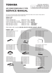
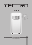
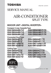
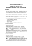
REMOTE CONTROLLER FOR AIR CONDITIONER (SPLIT TYPE) Owner’s Manual Remote Controller Model name: Wireless Remote Controller Kit RBC-AX31U(W)-E RBC-AX31U(WS)-E Generic model name RBC-AX31U(W)-E RBC-AX31U(WS)-E Owner’s Manual Remote controller for air conditioner (Split type) Wireless remote controller and signal receiving part WH-H1JE2 (Wireless remote controller model name) 1 English Manuel du proprietaire Télécommande pour climatiseur Français (Type split) 15 Betriebsanleitung Fernbedienung für klimagerät (Split-typ) 29 Deutsch Manuale del proprietario Telecomando per condizionatore Italiano 43 d’aria (Tipo split) Manual del propietario Control remoto para aire acondicionado (Tipo split) 57 Manual do utilizador Controlador remoto para ar condicionado (Tipo split) 71 Gebruiksaanwijzing Afstandsbediening voor airconditoner (Gesplitst type) 85 Español Português Nederlands Εγχειρίδιο χρήσης ΤηλεΧειριστηριο για κλιματιστικο Ελληνικά 99 (ΤυΠου split) Руководство пользователя Пульт дистанционного упРавлениЯ длЯ Русский 113 кондиционеРа (Сплит-системы) Wireless remote controller (WH-H1JE2) Signal receiving part Kullanım Kılavuzu Klİma İçİn uzaktan kumanda 127 Türkçe (Split tİp) Owner’s Manual Wireless Remote Controller Kit • Please read this Owner’s Manual carefully for correct use before using your Wireless Remote Controller Kit. Be sure to read “PRECAUTIONS FOR SAFETY” • After you read this manual, please keep it with the Owner’s Manual of the air conditioner in a place where you can access it quickly. Contents 1 PRECAUTIONS FOR SAFETY . . . . . . . . . . . . . . . . . . . . . . . . . . . 2 2 PART NAMES AND FUNCTIONS . . . . . . . . . . . . . . . . . . . . . . . . . 3 3 HOW TO OPERATE INDOOR UNIT . . . . . . . . . . . . . . . . . . . . . . . 7 4 HOW TO OPERATE THE TIMER . . . . . . . . . . . . . . . . . . . . . . . . . 8 5 HOW TO ADJUST AIR DIRECTION . . . . . . . . . . . . . . . . . . . . . . . 9 6 SLIDE SWITCH . . . . . . . . . . . . . . . . . . . . . . . . . . . . . . . . . . . . . . 10 7 HOW TO INSERT BATTERIES . . . . . . . . . . . . . . . . . . . . . . . . . . 10 8 HOW TO HANDLE THE REMOTE CONTROLLER . . . . . . . . . . . 11 9 NOTES ON PROPER USE . . . . . . . . . . . . . . . . . . . . . . . . . . . . . . 11 10 ADDRESS . . . . . . . . . . . . . . . . . . . . . . . . . . . . . . . . . . . . . . . . . . 12 11 HOW TO PERFORM EMERGENCY OPERATION . . . . . . . . . . . 13 12 BEFORE ASKING FOR REPAIR WORK . . . . . . . . . . . . . . . . . . 14 1-EN –1– Owner’s Manual Wireless Remote Controller Kit 1 PRECAUTIONS FOR SAFETY WARNING WARNINGS ABOUT INSTALLATION • Make sure to ask the qualified installation professional in electric work to install the remote controller. If the remote controller is inappropriate installed by yourself, it may cause electric shock or fire, etc. • Make sure to install the air conditioner specified by TOSHIBAand ask the exclusive dealer when installing. If the air conditioner is installed by yourself, it may cause electric shock or fire, etc. WARNINGS ABOUT OPERATION • Prevent any liquid from falling into the remote controller. Do not spill juice, water or any kind of liquid. It may cause machine failure, electric shock or fire, etc. • When you are aware of something abnormal with the air conditioner (smells like something burning, etc.), immediately turn off the main power supply switch or circuit breaker to stop the air conditioner, and make contact with the dealer. If the air conditioner is continuously operated with something abnormal, it may cause machine failure, electric shock or fire, etc. EN WARNINGS ABOUT MOVEMENT AND REPAIR • Do not repair any unit by yourself. Whenever the air conditioner needs repair, make sure to ask the dealer to do it. If it is repaired imperfectly, it may cause electric shock or fire, etc. • When reinstalling the air conditioner, contact with the dealer. If the installation is insufficient, it may cause electric shock or fire, etc. CAUTION CAUTIONS ABOUT INSTALLATION • Do not install the remote controller in a place where its signals do not reach the indoor unit. • Do not install the remote controller in the place under the direct sunlight and close to any heat source. It may cause machine failure. • The fluorescent lamp with rapid start system or inverter system may disturb the signal reception. For details, contact with the dealer of the air conditioner you have purchased. CAUTIONS ABOUT OPERATION • Do not drop or apply strong shock to the air conditioner. It may cause remote controller failure. • Use batteries that meet the specifications. –2– 2-EN Owner’s Manual Wireless Remote Controller Kit 2 PART NAMES AND FUNCTIONS Remote Controller (WH-H1JE2) • Up to 8 indoor units in a group can be controlled by one remote controller. 7 1 11 12 2 Used after batteries are replaced or the slide switch is switched. (See page 10) 8 9 10 11 ADR 6 7 8 ACL SENSOR 15 16 17 18 12 1 2 Transmitting part Start/Stop button Starts and stops the air conditioner alternately. 3 4 5 Air volume button 14 Setup temperature button Every pushing this button, temperature rises by 1°C. Every pushing this button, temperature lowers by 1°C. 15 Swing/air direction button (See page 9) 16 17 Address button (See page 12) Ventilation button The remote controller is not operated even if this switch is pushed. (no function) 18 Sensor button Selects the temperature sensor of the remote controller. The temperature sensor of the indoor unit is selected by default. While the indoor unit temperature sensor is selected, is displayed on the display. Time setup button Filter button No function 3-EN Operation mode display AUTO louver display differs according to the installed unit. (See page 9) Used for timer setting. (See page 8) 6 Remote controller sensor 13 Mode select button Selects an operation mode. Cover Displays the air conditioner operation mode. (This illustration shows all display contents.) 9 10 Battery compartment (See page 10) Senses the ambient temperature when the remote controller is selected with the sensor button. 14 3 4 5 Slide switch (See page 10) Slide the cover downward holding its both sides. 13 ADR RESET button –3– Owner’s Manual Wireless Remote Controller Kit Signal Receiving Part • The signal receiving part is attached to the indoor unit. • Hereinafter, all remote controller button names are indicated with respective symbols displayed on the remote controller. Example: Start/Stop button → 4 5 6 1 The rear of signal receiving part The following switches are provided on the rear of the signal receiving part. For their settings, contact the dealer from whom you purchased the air conditioner. • Header/follower switch Normally, set this switch to “HEADER” to use the remote controller as a header. The remote controller can be used together with the wired remote controller (sold separately). • Test run switch Do not use this switch in normal operation, but use for service. • Address switches (See page 12) Distinguish transmit signals and receive signals. 2 CAUTION 3 1 Emergency operation button (See page 13) 2 Signal receiver Receives signals from the remote controller. 3 LEDs Any of these LEDs flashes during an error state. When an LED flashes, see “BEFORE ASKING FOR REPAIR WORK” on page 14. 4 Run LED (green) Lights while the air conditioner is working. 5 EN • If “pi, pi” sound is heard with the Run LED lighting and the Timer and Not Ready LEDs flashing alternately while the heat-pump type air conditioner is used, desired operation mode is disabled. The same is true if the AUTO mode is selected in a model that is not provided with the cool/heat auto function. • Even if you push , or when remote controller operation is disabled by the central control or other means, “pi” is heard 5 times and the button operation is not accepted. Timer LED (green) Lights while the timer is reserved. 6 Not Ready LED (orange) • Lights in the heating mode at the beginning of operation or during defrosting or when the temperature controller is activated. • Flashes during an error state. –4– 4-EN Owner’s Manual Wireless Remote Controller Kit Display section All inticators are shown in the right and the lower figures for the explanation. Only selected contents are display in actual operation. • When turning on the leak breaker at the first time, [SET DATA] flashes on the display part of the remote controller. While this display is flashing, the model is being automatically confirmed. Accordingly, wait for a while after [SET DATA] display has disappeared, and then use the remote controller. Display section ADR ADR ACL Operation section SENSOR 1 5 2 6 7 8 2 3 ADR 4 10 1 Transmitting indication Displayed while operating the switches of the remote controller. 2 Mode display The selected operation mode is displayed. 3 Fan mode select display 6 The selected set up temp. is displayed. 7 4 8 5 Timer time display Time of the timer is displayed. (When a trouble occurs, the check code is displayed.) 10 Timer SET IN setup display ” is displayed, clean the air When pushing the Timer SET IN button, the display of the timer is selected in order of [OFF] → [OFF] repeat OFF timer → [ON] → No display. CHECK display Displayed while the protective device works or a trouble occurs. 5-EN SWING display Displayed during up/down movement of the louver. 9 Filter display If “FILTER filter. Louver position display Displays louver position. The selected fan mode is displayed. (AUTO) (HIGH) (MED.) (LOW) Set up temperature display –5– Owner’s Manual Wireless Remote Controller Kit Operation section Push each button to select a desired operation. • The details of the operation needs to be set up once, afterward, the air conditioner can be used by pushing ON/OFF only. 5 1 2 3 6 ADR 4 1 SENSOR ACL Operation select button 6 Selects the desired operation mode. 2 Fan mode select button Time setup button Used for timer setting. (See page 8) 4 Check button The CHECK button is used for the check operation. During normal operation, do not use this button. 5 Temperature set button Adjusts the room temperature. Set the desired set temperature by pushing or . EN Start/Stop button When the button is pushed, the operation starts, and it stops by pushing the button again. When the operation has stopped, the operation lamp and all the displays disappear. Selects a fan mode. 3 7 7 Filter button Resets (Erases) “FILTER ” display. OPTION : Remote controller sensor Usually the temperature sensor of the indoor unit senses the temperature. The temperature on the surrounding of the remote controller can also be sensed. For details, contact the dealer from which you have purchased the air conditioner. –6– 6-EN Owner’s Manual Wireless Remote Controller Kit 3 HOW TO OPERATE INDOOR UNIT 5 Auto, Heat, Dry, Cool, Fan Push . When the operation is stopped with the remote controller, the outdoor unit fan keeps running in some cases even after the compressor of the outdoor unit has stopped. • The automatic cooling/heating and heating functions are not provided for cool-only types. • The automatic cooling/heating is not available for heat pump types that are not provided with the automatic cooling/ heating function. Power Turn on the power switch on the remote controller 12 hours before starting operation. * The remote controller is disabled for approx. 1 minute after the indoor unit has been powered on. This is normal. (The signal from the remote controller is received, but the receive data is discarded.) 2 3 1 2 Automatic Cooling/Heating 1 When all indoor units in the same refrigerant system are under the group control, heating or cooling operation is automatically performed according to the difference between the setup temperature and the room temperature. Push . Push to select an operation mode. Push to select a fan speed. • When the Auto mode is selected, the fan speed changes automatically. The fan speed does not change automatically in the Fan mode. 4 Push either button of desired temperature. to select the • Temperature setting is not available for the Fan mode. 7-EN • If the room is not well heated with FAN during heating, change the fan speed to FAN or FAN . Although selected fan speed is displayed, some indoor unit types are not provided with the air volume change function. (Fan speed is constant.) • If the unit operation cannot be stopped in the usual manner, turn off the power switch and contact the dealer from whom you purchased the air conditioner. 4 • Select Auto, Heat, Dry, Cool, or Fan. 3 Stop Self cleaning The self cleaning operation starts automatically after running the cooling/dry mode (10 minutes or more) to keep the inside of the indoor unit clean. (For details, refer to the Owner’s Manual of the indoor unit.) To stop self cleaning forcibly, push twice quickly. –7– Owner’s Manual Wireless Remote Controller Kit 4 HOW TO OPERATE THE TIMER • After the timer has been set, put the remote controller at a position where signals of the remote controller can reach the signal receiver on the indoor unit. The timer operation signal is transmitted from the remote controller. • Set the timer while an operation mode is displayed as follows: Use the timer in the following cases Mode displayed <Usage Examples> ▼ Setting OFF timer (Example) To stop operation in 30 minutes 1 Push Timer . and the time flash on the display. 2 Set the time to 0.5 with TIME . 3 Push . flashing. or and the time stop To stop the air conditioner when the preset time has passed OFF timer To stop the air conditioner each time when the preset time has passed Repeat OFF timer ▼ Setting repeat OFF timer (Example) To stop operation in every 2.5 hours To operate the air conditioner when the preset time has passed ON timer 1 twice. and the time flash on the display. Timer period The setup time increases by 0.5 hours (30 minutes) each time you push . The maximum setup time is 72.0 hours. The setup time decreases by 0.5 hours (30 minutes) each time you push . The minimum setup time is 0.5 hours. Timer display Each time you push Timer display changes as follows: Push Timer EN , the timer 2 Set the time to 2.5 with TIME . 3 Push . flashing. or and the time stop The OFF timer is activated and the operation stops in 2.5 hours. When you push again to restart the operation, it stops in 2.5 hours. ▼ Setting ON timer (Example) To start operation in 8 hours 1 Push Timer three times. and the time flash on the display. 2 Set the time to 8.0 with TIME . 3 Push or . The operation mode disappears, and and the time stop flashing. ADR No display ▼ Canceling timer operation Push . The timer display disappears. –8– 8-EN Owner’s Manual Wireless Remote Controller Kit 5 HOW TO ADJUST AIR DIRECTION • While the air conditioner is not working, the louver (air direction adjusting plate) is closed automatically. • During the preparation for heating, the louver is directed upward and it starts swinging after the preparation for heating is canceled though the automatic louver display on the remote controller shows swinging even during this period. To set air direction To stop swinging Push during operation. Air direction changes each time you push the button. Push once again while the louver is swinging. The louver can be stopped at a desired position. Then air direction can be set again from the uppermost by pushing . Heating mode Keep the louver pointed downward so that discharged hot air reaches the floor. Initial setting * The louver does not stop while it is pointed downward during cooling or drying. Even if you attempt to stop the louver with the louver pointed downward during swinging, it stops at the third position from the uppermost direction. Fan mode To start swinging Push to set the louver direction to the lowest, and then push again. Louver swinging appears on the display and air direction automatically changes up and down. Initial setting All operation modes Cooling/dry mode Swing Keep the louver pointed upward. Otherwise, dew drop may form around the discharge port and drop from the unit. Continuous operation Display when swinging is stopped Initial setting Heating/fan mode Cooling/dry mode • This remote controller has no function to set air direction individually or powersaving operation or to change the swing mode that are described in the Owner’s Manual of the indoor unit. 9-EN –9– Owner’s Manual Wireless Remote Controller Kit 6 SLIDE SWITCH • The settings of operation mode display and air direction display vary as follows depending on the indoor unit in use. • Use a fine-tipped tool to change the switch setting. • Push the RESET button after the switch setting is changed. 1 Louver display switch View with the cover removed SENSOR ACL Louver display of the remote controller 1 2 Slide switch position * Set the slide switch to “S.” Otherwise the air direction adjustment and louver display are disabled. 2 RESET button Operation mode switch Heat pump (With automatic cooling/heating) Heat pump (Without automatic cooling/heating) EN Cool-only Operation mode display of the remote controller Slide switch position • Before using the air conditioner, check that the slide switch is set as shown in this table. For details of slide switch setting, contact the dealer from whom you purchased the air conditioner. 7 HOW TO INSERT BATTERIES 1 Slide and remove the cover downward while holding both sides of the cover. 2 Insert two AAA alkaline batteries correctly matching the (+) and (-) polarities with the indication. 3 Push the RESET button with a fine-tipped tool and attach the cover. • Replace batteries when the display on the remote controller has become dim or when signals from the remote controller cannot be received at the normal distance from the signal receiving part. Alkaline batteries should be replaced once a year. • Replace two batteries at the same time with new ones of the same type. • When you do not use the remote controller for a long time, take out the batteries. • Discard exhausted batteries at a designated place. – 10 – RESET button Cover 10-EN Owner’s Manual Wireless Remote Controller Kit 8 HOW TO HANDLE THE REMOTE CONTROLLER • Point the transmitting part of the remote controller at the signal receiving part of the indoor unit. When a signal is received normally, “pi” sound is heard once. (“Pi, pi” is heard only at the beginning of operation.) • The standard signal receivable distance from the signal receiving part of the indoor unit is approx. 7 m. The distance varies somewhat with the battery capacity or other conditions. • Do not put anything that blocks signals between the remote controller and the signal receiving part of the indoor unit. • Do not put the remote controller at a place exposed to direct sunlight or air from the indoor unit or near a heater. • Do not drop or throw the remote controller or wipe it with water. • Signals from the remote controller may not be accepted in a room equipped with a rapid start-type or inverter-type fluorescent light. For details, contact the dealer from whom you purchased the air conditioner. To set the Remote Controller on the Wall • Push at the installation position on the wall to check that the signal from the remote controller is received correctly. • To take the remote controller out of the holder, pull it toward you. Fix the remote controller holder with screws. 1 Put on. Remote controller holder 9 Setting the remote controller into the holder 2 Push NOTES ON PROPER USE • Put the remote controller within the specified distance from the signal receiving part of the indoor unit. Failure to do so may result in malfunction. Be sure to put the remote controller in a room where the indoor unit is installed. • When pushing a button on the remote controller, point the remote controller at the signal receiving part of the indoor unit. When the signal receiving part has correctly received a signal, it emits a “pi” sound. • Do not put the remote controller behind a curtain or the like. 11-EN – 11 – Owner’s Manual Wireless Remote Controller Kit 10 ADDRESS When two or more indoor units controlled by the same wireless remote controller are installed in a room, a unique address can be set for each indoor unit to prevent interference. Up to 6 indoor units can be controlled independently by the remote controller by matching the address switch setting of the signal receiving part with the address displayed on the remote controller. The signal receiving part (inside the ceiling panel or indoor unit) has address switches for receiving addresses, and the remote controller has an address button for transmitting addresses. For details, contact the dealer from whom you purchased the air conditioner. Checking Addresses Push ADR on the remote controller. The current address appears on the display. When this address equals the address of the address switch in the signal receiving part (inside the ceiling panel or indoor unit), the buzzer sounds. When the address on the display is “ALL,” the buzzer sounds and the remote controller is enabled regardless of the address switch setting in the signal receiving part. Transmit signals while pointing the remote controller at the signal receiving part of the indoor unit to be controlled. EN Matching Addresses Address setting on the remote controller 1. Push ADR for at least 4 seconds. “Address” lights up on the display and the current address flashes. 2. Each time you push ADR , addresses change cyclically like ALL → 1 → 2 → 3…→ 6 → ALL. Select an address that matches the address switch setting in the signal receiving part of the indoor unit to be controlled. 3. Push . The flashing address changes to lighting and is displayed for 5 seconds. When this address equals the address switch setting in the signal receiving part, the buzzer sounds. Address displayed on the remote controller (The location of ADR is shown on page 3.) Address switch setting in the signal receiving part (inside the ceiling panel or indoor unit) Address Address Address Address * Any setting is OK. Set S001 to the right position (for addresses 1, 2, and 3) or to the left position (for addresses 4, 5, and 6). Set S002 to the right position (for addresses 1 and 4), to the center (for addresses 2 and 5), or to the left position (for addresses 3 and 6). – 12 – 12-EN Owner’s Manual Wireless Remote Controller Kit 11 HOW TO PERFORM EMERGENCY OPERATION In the event of an emergency shown below, push emergency operationeon the signal receiving part (inside the ceiling panel or indoor unit) for emergency operation. • The batteries of the remote controller have been exhausted. • The remote controller is out of order. • The remote controller has been lost. 1 2 1 Start Push emergency operation. (When the emergency operation is started at a room temperature of 24°C or more, the air conditioner enters the cooling mode. When the emergency operation is started at a room temperature below 24°C, the air conditioner enters the heating mode.) 2 Stop Push emergency operation once again. REQUIREMENT The test run switch in the signal receiving part is used for a test run during the installation work. Do not use it for other purposes. 13-EN – 13 – Owner’s Manual Wireless Remote Controller Kit 12 BEFORE ASKING FOR REPAIR WORK Check the following before asking for repair work. Check again Phenomenon Possible cause Measures Operation does not start even if the switch is turned on. The air conditioner is not working or a power failure has occurred. Push on the remote controller again. (See page 7) The power switch is not turned on. Turn on the power switch if it is off. (See page 7) The air conditioner is in the ON timer operation. Cancel the timer operation. (See page 8) The batteries of the remote controller have been exhausted. Replace the batteries. (See page 10) The LEDs on the signal receiving part are not in normal state or operation mode is not correct. Change the operation mode. (See page 4) “Auto” or “Heat” is displayed on the display though the air conditioner is cool-only type. Change the slide switch setting of the remote controller.(See page 10) Dual swing, cycle swing, individual louver position, or power-saving cannot be set. This type of remote controller cannot set such functions. EN Contact the dealer from whom you purchased the air conditioner. Phenomenon The LEDs flash. Possible cause Communication error between signal receiving part and indoor unit or address setup error when the wired remote controller is used Communication error between indoor unit and outdoor unit The protective device of the indoor unit is activated. The protective device of the outdoor unit is activated. Temperature sensor error The compressor of the outdoor unit is protected. The air conditioner is performing a test run. Set the test run switch to OFF. LEDs on the signal receiving part : OFF : Flashing (at intervals of 0.5 seconds) LED color : Green : Green : Orange Check these items. If any of these problems still remains, stop the operation, turn off the power, and then notifies the dealer from whom you purchased the air conditioner of the model name and details of the error (including LED flashing state). Never repair any part by yourself as it is dangerous. – 14 – 14-EN