1
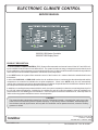
ELECTRONIC CLIMATE CONTROL
SERVICE MANUAL
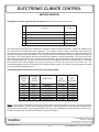
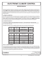
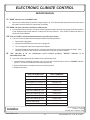
The pigtail connector supplied with the system (PC4) utilizes the following color codes:
PC4
/J4
pin
FUNCTION
COLOR
1
FRONT FURNACE THERMOSTAT (BLUE)
WHT/BLUE
2
FRONT FURNACE THERMOSTAT (BLACK)
3
KEYED - NOT CONNECTED
4
REAR FURNACE THERMOSTAT (BLACK)
BLK
5
REAR FURNACE THERMOSTAT (BLUE)
BLU
WHT/BLK
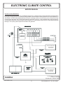
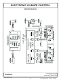
The Control Module operates the air conditioner compressors and fans via three relays with 12 VDC coils supplied by the
A/C manufacturer and mounted in their equipment. The contacts on these relays are internally wired by the A/C
manufacturer to the 120 VAC supply line for each unit and connect the compressor with the low, or high speed taps on the
fan motor to that supply line when operated. The wiring between the Control Module and these relays is low voltage (12
VDC) wiring. The Control Module uses high-side switching to operate the corresponding relays. One side of each of the
relay coils is connected together. This "common" lead is connected to ground through the Control Module and should not
be grounded anywhere else. The other side of each of the coils is brought out to one of three separate leads. These leads
are connected to the Control Module via a four-pin connector: J2 for the A/C1 unit, and J3 for the A/C2 unit. The
corresponding pigtail connectors, PC2 and PC3, are supplied with the system. PC3, the A/C2 (rear) connector, is marked
in red in order to differentiate it from Pc2.
The following table indicates the connection and control states:
MODULE
CONN
PIN
PIGTAIL
WIRE
COLOR
FUNCTION
“ON”
VOLTAGE
“OFF”
VOLTAGE
J2-1
J2-1
J2-3
J2-4
J3-1
J3-2
J3-3
J3-4
BLU
GRY
GRN
YEL
BLU
GRY
GRN
YEL
COMMON
LOW FAN
HIGH FAN
COMPRESSOR
COMMON
LOW FAN
HIGH FAN
COMPRESSOR
<1 VDC
+12 VDC
+12 VDC
+12 VDC
<1 VDC
+12 VDC
+12 VDC
+12 VDC
<1 VDC
<1 VDC
<1 VDC
<1 VDC
<1 VDC
<1 VDC
<1 VDC
<1 VDC
NOTE: The PC2 and PC3 pigtail wire colors are included for reference only to identify the function of the wires emanating
from the Control Module. The wire colors emanating from the A/C1 and A/C2 units may, or may not agree with these colors.
Always refer to the installation manual supplied with the A/C unit, or see “Identifying control lead functions on the A/C unit”,
in order to match the wire color/functions with those on the Control Module.
131 Eisenhower Lane North
Lombard, IL 60148
630.268.0010 / 1.800.251.2408
Intellitec
www.intellitec.com
4
P/N 53-00591-597 Rev. B 041205