1
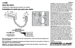
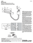
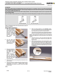
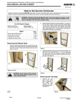
Ultimate Inswing French Door
Service Guide - 2011 Platform
The Ultimate Inswing French Door (UIFD) features X, XX, XO/OX, OXO, OOX/XOO and OXXO operation. The
UIFD has a newly designed sill with an interior flange and through sill water management system. For panels that
are binding or not square in the frame, first check that the unit frame has been installed in a square, plumb and true
condition. The UIFD adjustable hinges are designed to help align the panels to the frame due to minor
misalignment issues. The sill must not be humped or the head jamb sagging, especially on XX units.
Table of Contents
Swinging Door Troubleshooting . . . . . . . . . . . . . .
UIFD Parts Manual . . . . . . . . . . . . . . . . . . . . . . . . .
Adjustable Hinge - Panel Alignment . . . . . . . . . . .
Butt Hinge - Panel Alignment . . . . . . . . . . . . . . . . .
Latch Bolt Reversal Instructions . . . . . . . . . . . . . .
Glass Replacement Instructions . . . . . . . . . . . . . .
Multi-Point Lock System Replacement . . . . . . . . .
Sill Strike Adjustment . . . . . . . . . . . . . . . . . . . . . . .
Head Jamb Strike Adjustment . . . . . . . . . . . . . . . .
Stationary Panel Replacement - Screws . . . . . . . .
Stationary Panel Replacement - Brackets . . . . . .
Weather Strip Replacement - Wood Door . . . . . . .
Corner Gasket and Part Stop Weather Strip . . . . .
1
1
1
1
1
2
2
2
2
2
5
6
6
Panels not aligned
Figure 1
2. Make horizontal adjustment first. To adjust panel(s)
horizontally away from jamb, turn horizontal
adjustment screw counter-clockwise using 5/32"
Allen wrench provided. To move panel toward
jamb, turn Allen screw clockwise. See figure 2.
Make vertical adjustments only after the horizontal
adjustments are complete.
Swinging Door Troubleshooting
See Marvin Service Manual for General
Troubleshooting
guide
and
Swinging
Troubleshooting guide.
Panels aligned
Door
Door
UIFD Parts Manual
See the Marvin Parts Manual for replacement parts and
parts identification.
You Will Need to Supply
Safety glasses
Stiff bladed putty knife
Phillips screwdriver
Pliers
5/32" Allen wrench
Rubber hammer
Counter-clockwise
Clockwise
Figure 2
3. To adjust panel(s) vertically in an upward motion,
turn vertical adjustment screws clockwise equally
on all of the hinges using a 5/32" Allen wrench
provided. To lower panel, turn Allen screws
counter-clockwise on all hinges. See figure 3.
Adjustable Hinge - Panel Alignment
Before adjusting the panels ensure that the frame and
sill are in a square, plumb, level and true condition. See
#19970479 Door General Installation Instructions.
Adjusting the panels will not correct a humped sill,
sagging head jamb or frame that is not square and
true. The adjustable hinges can correct minor
misalignments in the door system.
1. After establishing that the door frame is in a square
and true condition inspect for even reveals
between the door panels and frame. On XX and
OXXO panels the tops of the panels should be
even. See figure 1.
Counter-clockwise
Clockwise
Figure 3
2012-08-21
19972249
1
Ultimate Inswing French Door
Service Guide
Butt Hinge - Panel Alignment
1. Doors equipped with
butt hinges have 1/32"
shims behind each leaf
on all hinges (two
shims/hinge). Horizontal
panel adjustment is
possible by removing or
redistributing
these Figure 4
shims. See figure 4.
Rotated 180°
(thin side to the exterior)
Shims
As shipped from the factory
(thick side to the exterior)
Latch Bolt Reversal Instructions
Figure 6
See Marvin Service Manual for Latch Bolt Reversal
Instructions. This procedure does not require removing
the door panel.
Head Jamb Strike Adjustment
1. If the multi-point lock is engaging hard at the head
jamb on the lock side of the door use a Phillips
screwdriver to remove the strike. Rotate the strike
180° and reinstall.
Glass Replacement Instructions
See Marvin Service Manual for Door Panel Glass
Replacement Instructions.
Stationary Panel Replacement - Screws
Multi-Point Lock System Replacement
Screw through panel replacement procedures are
recommended for wood and clad stationary panels with
operator panels hinged off of the stationary panel, such
as XO/OX units.
See Marvin Service Manual for Multi-point Lock
Replacement Instructions.
Sill Strike Adjustment
1. If the multi-point lock is closing hard at the sill on
the lock side of the door insert a paint can opener
into the strike under one of the sill strike tabs. Pull
back and lift up to release the strike from the sill.
See figure 5.
Seek Assistance
Door panels can be heavy and difficult to handle. Use
appropriate glass handling equipment and an assistant
if necessary.
NOTE: If you ordered your replacement panel with
SDL bars, the interior SDL bar cannot be applied to the
stationary panel until after it has been secured in the
frame. See SDL Field Service Guide.
Pull back on tab, lift out
and rotate 180° degrees
NOTE: These instructions are for installed doors that
will not be removed to replace the panel(s). For doors
that are not installed or easily removed, back out
stationary panel fastening screws from the outer
perimeter of stationary jamb and head jamb to replace
the panel.
Figure 5
Stationary Panel
2. Rotate the strike 180° and press the strike back
into the sill, keeping the strike parallel with the sill
surface. See figure 6.
2012-08-21
19972249
Parts Needed
SDL if specified
You Will Need to Supply
Safety glasses
Stiff bladed putty knife
Masonry chisel
Pliers
1/8 x 8" drill bit
Cordless drill
3# hammer
Dust mask
Bent screwdriver
Rubber hammer
®
#9 x 5" Torx trim head screws w/ #15 Torx driver
2
Ultimate Inswing French Door
Service Guide
4. Next, remove 6 - 8 screws that secure the mullion
casing to the mullion casing base. See figure 9.
1. Remove operating panel (if hinged off the
stationary panel to be replaced). Back out hinge
screws from stationary panel, leave hinges
attached to operating panel. Save screws for
reuse. Carefully store operating panel in a safe
place.
2. Locate stationary panel attachment screws by
sliding a masonry chisel between the space of the
stationary jamb and panel (both side and head).
When a screw is located you will hear a distinct
metal sound. Shear off each screw (3 - 4 along
jamb and 4 at the head jamb) with one blow of a 3#
hammer striking the masonry chisel. See figure 7.
Remove
screws
Figure 9
5. On wood units to detach the panel from the mull
post, first expose the screws holding the astragal
base to the mull post by removing the astragal and
panel weather strip. Remove the screws securing
mullion casing base to mullion casing. See
figure 10.
Mull base
Mull post
Figure 7
3. If replacing a wood stationary panel skip to step 5.
Remove clad mullion casing cover by hooking a
bent screwdriver, similar tool, at one end of the
cover. Gently pry off the cover if it is to be reused.
See figure 8.
Figure 10
6. You can now remove the panel by tilting the top of
the panel slightly inward, lift upward to remove
panel from the frame.
IMPORTANT
The mullion casing will remain in place, attached at
head jamb and sill of the frame. The mullion casing
base will stay attached to the stationary panel when it is
removed.
Mull cover
7. Install the stationary panel by first removing the
stationary jamb side and head jamb glazing stops
and connecting barbs as one component by
carefully prying away from panel. Save glazing
stops for reuse later. Note location of original
screws cut earlier and mark locations on the new
panel on the opposite side near the spacer tacks
Figure 8
2012-08-21
19972249
3
Ultimate Inswing French Door
Service Guide
as shown in figure 11. The new screw locations
must be near the spacer tacks but not align with
original screw locations.
10. Place a piece of cardboard over the glass where
new pilot holes will be drilled. It can be secured in
place using masking tape. The cardboard will
prevent the glass from being scratched.
Old screw location
11. Using a drill with the 1/8 x 8" drill bit, drill new pilot
holes through the stile and top rail of the panel into
the stationary jamb and head jamb. DO NOT angle
the drill more than 6 degrees. See figure 14.
Glazing stop
Spacer
tack
Mark location
for screw
Figure 11
Do not exceed
6 degrees
8. If installing a wood stationary panel skip to step 9.
Place new clad stationary panel in frame ensuring
that the mullion base and mullion casing are
aligned properly. Reverse the procedure described
earlier in step 4. Replace 6 - 8 screws that secure
mullion casing to panel. See figure 12.
Cardboard to protect glass
Figure 14
12. Using the Torx® bit, secure the panel to the frame
using #9 x 5" Torx trim head screws. Be sure to
countersink the screw heads so they are below the
connecting barb kerf. See figure 15.
Cardboard to protect glass
Figure 15
Figure 12
13. Install the clad mullion casing cover onto the
exterior of the mullion casing with a rubber mallet
or wood block and hammer. Take care not to
damage the cover. See figure 16.
9. On wood units place the stationary panel into the
frame. Reinstall screws securing mull casing to the
stationary panel. Apply new weather strip along the
entire length of the mull base See figure 13.
Mullion casing
cover
Figure 16
Mull
base
weather strip
Panel weather strip removed for illustrative
purposes
14. Install glazing stops and interior SDL bars, if
applicable, see SDL Field Service Guide.
Figure 13
2012-08-21
19972249
4
Ultimate Inswing French Door
Service Guide
Stationary Panel Replacement - Brackets
jamb stop removal and installation instructions see
page 3 of the UIFD Supplemental Instructions
#19970483. Use a flat bar to remove the weather
strip from the frame.
NOTE:
Stationary bracket panel replacement
procedures - recommended for clad units.
Parts Needed
Replacement Stationary
Stationary brackets
Panel
You Will Need to Supply
Safety glasses
Stiff bladed putty knife
Masonry chisel
Pliers
5/32" Allen wrench
Rubber hammer
2# hammer
1. Remove operating panel (if hinged off the
stationary panel to be replaced). Back out hinge
screws from stationary panel, leave hinges
attached to operating panel. Save screws for
reuse. Carefully store operating panel in a safe
place.
Figure 18
6. Mark the sides of the panel that will receive the
stationary bracket 2" - 4" (51 - 102) from each corner
then 12" - 14" (305 - 356) thereafter. Install brackets
with two #8x1" wood screws. See figure 19.
2. Locate stationary panel attachment screws by
sliding a masonry chisel between the space of the
stationary jamb and panel (both side and head).
When a screw is located you will hear a distinct
metal sound. Shear off each screw (3 - 4 along
jamb and 4 on the head jamb) with a masonry
chisel and striking it with one blow by a 3# hammer.
See figure 17.
Fasten to panel
with #8x1" screws
Figure 19
7. Ensure that the spacer buttons are in place along
the side and head jambs. Install the panel and
push tight up against the weather strip.
8. Bend bracket so the corner of the bracket seats
into the corner of the frame weather strip kerf.
Secure each bracket to the frame with two 70
degree angled #8 x 1" wood screws. See figure 20.
Figure 17
3. See previous instruction (step 3 - 5) for removal of
the panel from the mull post side.
4. You can now remove the panel by tilting the top of
the panel slightly inward, lift upward to remove
panel from the frame.
Bend bracket into
place and fasten
IMPORTANT
The mullion casing is attached at the head jamb and sill
of the frame. The mullion casing base will stay attached
to the stationary panel when it is removed.
5. To install the new panel start by removing the side
stops with a flat bar. See figure 18. For clad unit
2012-08-21
19972249
Figure 20
5
Ultimate Inswing French Door
Service Guide
9. For stationary panels installed in multiple wide
configurations with the operator panel hinged off of
the stationary panel, removing the top rail glazing
bead and screwing through the top rail into the
head jamb will be necessary. See steps 7 - 13 of
the previous instruction.
3. Measure and cut V796 to length. Starting at one
end of the jamb slide the leg of the weather strip
into the slot along the entire length of the door
jamb stop. Next press the barb into the kerf and tap
into place with a rubber hammer until fully seated.
See figure 22.
10. Reinstall weather strip and side stops. Reinstall
operating panels with hinges if applicable.
Install V796
weather strip
Weather Strip Replacement - Wood Door
This procedure is for replacing the side or head jamb
weather strip on a wood door without removing the
exterior part stop.
Parts Needed
Part stop weather strip - V796
You Will Need to Supply
Safety glasses
Utility knife
Measuring tape
Figure 22
1. Open the door panel to the fully open position.
Corner Gasket and Part Stop Weather Strip
2. Use a utility knife to remove the damaged jamb
weather strip and sufficient weather strip backing
to expose the kerf in the jamb part stop and access
to the slot in the door jamb. See figure 21.
IMPORTANT
If the part stop is removed and reinstalled, be sure the
part stop weather strip overlaps the corner gasket as
shown in figure 23. If the weather strip is not
overlapped properly, water and air infiltration could
result.
Part stop
Part stop weather strip
needs to overlap the
corner gasket
Slot
Remove this portion
of the weather strip
Sill
Corner gasket
Figure 21
Figure 23
2012-08-21
19972249
6
Ultimate Inswing French Door
Service Guide