Transcript
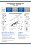
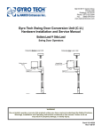
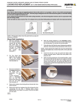
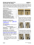
Double-Door Electromagnetic Lock
Installation User Guide
(Indoor Series)
※12 or 24VDC auto voltage selection
Spec/Model
GEM-D600
GEM-D800
GEM-D1200
Holding Force
600lbs (272kg) x2
800lbs (363kg) x2
1200lbs (545kg) x2
Voltage Input
12/24VDC
500mA/12VDC x2
250mA/24VDC x2
12/24VDC
500mA/12VDC x2
250mA/24VDC x2
12/24VDC
500mA/12VDC x2
250mA/24VDC x2
Current Draw
Basic Installation Concept & Accessories
UBK Bracket For
Glass Frame & Glass Door
General Installation
Glass
Frame
Door
Frame
12/24 VDC
Power
EM Lock
Self-tapping
Screw x10
Cable Wire
EM Lock
Door
Fixing Screw
x4
Inswing
Glass
Door
Outswing
Electromagnet x2
Anti-tamper Nut x4
EM Bracket For
Inswing Door With Cover
U Bracket For Glass Door
Mounting Plate
Door
Frame
Door
Frame
EM Lock
Glass
Door
Armature
Screw x2
EM Lock
Door
Rubber
Washer x2
Inswing
Outswing
Cover Screw x2
Sexnut Bolt
x2
PCB Cover
LZ Bracket For Inswing Door
Anti Residual
Magnetism
Button x2
L Bracket For Outswing Door
Door
Frame
Armature
Plate x2
Door
Frame
EM Lock
Allen Wrench
Door
Metal Washer x4
Guide Pin x4
EM Lock
Door
Outswing
Inswing
General Installation Steps & Maintainance
Trouble Shooting
1. Drill the armature plate holes in the door using the sticker template provided.
1. Sensor not functioning
2. Attach the armature plate to the door with the hardware provided per the illustration.
3. With the door closed, mark the door frame at the edge of the armature in order to
properly align the electromagnet to the armature.
4. Attach the mounting plate to the door frame using the self-tapping screws provided.
Align the mounting plate with the mark from the previous instruction.
5. Insert the wires through the hole in the mounting plate and into the electromagnet unit.
Attach the electromagnet unit to the mounting plate with the Allen head fixing screw.
6. Screw in the anti-tamper nuts to prevent unauthorized access and to prevent the fixing
screw from loosening over time.
- Align attachment of electromagnet and armature plate
- Modification of the PCB
2. Door not locked - Incorrect wiring or no power from power supply
3. Reduced holding force
- Poor contact of electromagnet and armature plate.
Be sure armature is loose enough that it can fully contact
electromagnet along the entire length.
- Make sure surface is not dusty or damaged.
- Improper input voltage or wire specifiction.
7. Connect the power wires according to the instruction and test the system.
8. It is recommended that you apply a light coat of silicon lubricant to the mating surface
on a monthly basis to prevent rust.
Copyright © 2010 Gianni Industries, Inc. All rights reserved.
P-MU-MA-GEM-D Ver.B
Publish: 2010.10.13