1
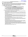
- TABLE OF CONTENTS-
ER6-SERIES 1:6 SERVICE MANUAL
DECEMBER 2009
II.
INSTALLATION
FOLDOVER 1:6 RAMP INSTALLATION
A. INSTALLATION GUIDELINES
Careful installation of the Ricon FoldOver 1:6 ramp contributes to proper and safe operation. Use the electrical
wiring diagrams in Figures 3-5.1 and 3-5.2 to supplement this section.
1.
LOCATING MOUNTING BRACKETS ON BUS FRAME
Use a rigid fixture that substitutes for the ramp assembly when positioning ramp mounting brackets on bus
frame. If the ramp assembly is used to position mounting brackets, verify that it is correctly located relative
to the vehicle floor, etc. Accurate positioning of brackets prevents twisting or warping of ramp frame when
installing and tightening mounting hardware. A warped frame may cause the ramp motion to be erratic.
Set height of ramp flooring surface flush to surrounding floor structure to prevent a tripping hazard.
2.
INSTALLING 1:6 RAMP IN FLOOR
The location of the ramp depends on its path of motion. The ramp must be positioned so it can move unobstructed through its required range of travel.
a. Trim away floor material to allow ramp assembly to drop into floor opening.
NOTE: Do Not install ramp trim (flange kit) until ramp is installed in bus. The ramp trim overlaps the perimeter
gap between the sides of the enclosure and bus structure. The typical gap between the sides of the
enclosure and the bus structure is 1/8 inch. Use shims to fill gap.
EYE BOLTS
LEFT
REAR
EYE BOLTS
RIGHT
FRONT
RSM0021300
FIGURE 2-1: RAMP LIFTING EYE BOLTS
WARNING!
TAKE EXTREME CARE WHEN POSITIONING RAMP INTO BUS. BE SURE TO FOLLOW
PROPER OPERATION AND SAFETY INSTRUCTIONS WHEN USING LIFTING DEVICE.
b. Refer to Figure 2-1. Attach lifting device hooks to pre-installed eye bolts.
c. Use lifting device to place ramp into bus.
32DER602.B
2-1
ER6-SERIES 1:6 SERVICE MANUAL
INSTALLATION
DECEMBER 2009
d. Lower ramp onto bus floor. Ensure that rear ramp flange rests on bus floor.
* MOUNTING BRACKET BOLTS (X3)
BUS STRUCTURE
SHIM SPACER
(SUPPLIED BY BUS
MANUFACTURER)
BUS STRUCTURE
REAR RAMP FLANGE
REAR
FRONT
FRONT BOLTS (X2)
(SUPPLIED BY BUS
MANUFACTURER)
8.29
(211)
BUS FLOOR
SURFACE
MIDDLE BOLTS (X2)
(SUPPLIED BY BUS
MANUFACTURER)
17.13
(435)
FACTORY INSTALLED
MOUNTING BRACKET
WITH BLOCK
21.90
(556)
51.66
(1312)
RIGHT SIDE VIEW
50.40
(1280)
1/4” MAX.
1/8” MIN.
10.63
(270)
12.00
(305)
9.33
(237)
21.25
(540)
24.00 33.76
(610) (858)
CL
18.65
(474)
1/8” MIN.
TOP VIEW
(SHOWN WITHOUT LH & RH TRIM)
NOTES:
DIMENSIONS IN INCHES
MILLLIMETERS IN PARENTHESES.
* REFERENCE MOUNTING BRACKET KIT
(P/N 43936 OR 44754) PER SPECIFIED APPLICATION.
BUS FLOOR
BUS FLOOR
CUT-OUT
RSM0021500
FIGURE 2-2: RAMP INSTALLATION
2-2
32DER602.B
ER6-SERIES 1:6 SERVICE MANUAL
DECEMBER 2009
INSTALLATION
NOTE: Refer to Figure 2-2. Ramp should sit securely and level on bus structure. If ramp does not sit level on
bus structure, install appropriate shim spacers accordingly.
CAUTION!
FOLLOW SEQUENCE FOR SECURING RAMP ONTO BUS STRUCTURE. DEVIATION FROM
THE INSTALLATION SEQUENCE CAN CAUSE RAMP WARPAGE.
e. Refer to Figure 2-2. Install and tighten two (2) front bolts.
f.
Refer to Figure 2-2. Install and tighten three (3) rear mounting bracket bolts.
NOTE: Mounting bracket kit is pre-installed at the factory and is configured according to bus manufacturer.
Refer to mounting bracket kit (i.e. Gillig Kit P/N 43936, Orion Kit P/N 44754) part number for vehicle in
stallation.
g. Inspect middle hardware installation. If space is present between the ramp frame and bus structure, install appropriate shim spacer then install and tighten two (2) middle bolts.
h. Refer to Figure 2-3. Install left and right trim pieces with attaching hardware provided.
SCREWS (X14)
TRIM (LH)
LEFT
REAR
RIGHT
TRIM (RH)
FRONT
RSM0021400
FIGURE 2-3: RAMP TRIM INSTALLATION
3.
INSTALLING VEHICLE WIRING HARNESS
Route wiring harness from vehicle ramp controls to rear of ramp. Use the supplied electrical installation kit
(Ricon P/N 44204) to connect vehicle control wiring to the ramp interface connector (Ricon P/N 43911).
See Table 2-1 for pin layout and signal descriptions.
a. Disconnect vehicle battery.
CAUTION
Be sure that harness does not interfere with any moving
parts, or binds against any parts, or is pinched in any way.
32DER602.B
2-3
ER6-SERIES 1:6 SERVICE MANUAL
INSTALLATION
DECEMBER 2009
b. Install Main Circuit Breaker Kit (P/N 36267). Avoid installing near a heat source.
c. Refer to Chapter 3.6 Electrical Diagrams and Figures 3-5.1 – 3-5.2. Route and install black ground
cable (P/N 43929) to ground connection and red power cable (P/N 43928) to positive connection block.
d. Route and install ramp interface harness (supplied by bus manufacturer) to ramp interface connection.
Table 2-1: J8 PIN LAYOUT AND DESCRIPTION
Pin
Wire color
Description
Volts
1
Red
Bus Power
P24V
2
Blue
Bus Power
P24V
3
Black
Ground
N/A
4
Brown
Ground
N/A
5
Orange
HV (High Voltage)
P24V
6
Yellow
HV (High Voltage)
P24V
e. Cycle ramp a few times to ensure ramp is working properly.
B.
FOLDOVER 1:6 RAMP ADJUSTMENTS
1.
CHAIN SPRING ASSEMBLY INSTALLATION AND ADJUSTMENT FOR MOTOR DRIVE SYSTEM
Removal and installation of the chain spring assembly may be necessary. Unequal tension on the springs
may cause different torques on ramp tray sprockets and will possibly cause ramp tray asymmetry error.
a. Refer to Figure 2-4. Install motor drive assembly into enclosure before installing chain spring assembly.
NOTE: Do not completely tighten bolts for motor drive system to allow some movement when installing
chain spring assembly. Bolts will be tightened after chain spring assembly is installed.
FIGURE 2-4: INSTALLED MOTOR DRIVE ASSEMBLY
b. Refer to Figure 2-5 and 2-6. Install left hand and right hand chain guides.
2-4
32DER602.B
ER6-SERIES 1:6 SERVICE MANUAL
DECEMBER 2009
INSTALLATION
FIGURE 2-5 and 2-6: FRONT AND REAR CHAIN GUIDES (LH SIDE SHOWN)
c.
Refer to Figure 2-7 and 2-8. Install pre-assembled chain spring assembly by routing onto small
sprocket.
NOTE: Pull chain spring assembly until spring is flush against spring supports.
FIGURE 2-7 and 2-8: ROUTE CHAIN SPRING (LH SIDE SHOWN)
d. Refer to Figure 2-9 and 2-10. Install spacer onto drive shaft then install self aligning bearing.
e. Install two washers and two bolts then tighten.
FIGURE 2-9 and 2-10: ROUTE CHAIN SPRING (LH SIDE SHOWN)
f.
Refer to Figure 2-11. Install Chain Spring Assembly by pushing spring rod DOWN and INWARD into
enclosure until Chain Spring Assembly is installed against the two spring supports in enclosure.
NOTE: Ensure that Chain Spring Assembly is securely installed against spring supports.
32DER602.B
2-5
INSTALLATION
ER6-SERIES 1:6 SERVICE MANUAL
DECEMBER 2009
FIGURE 2-11: SPRING ASSEMBLY (LH SIDE SHOWN)
g. Refer to Figure 2-12 and 2-13. Locate and mark an alignment mark on sprocket for reference to maintain sprocket hole at 5° inboard.
NOTE: Ensure that spring is securely installed against spring supports.
FIGURE 2-12 and 2-13: LARGE SPROCKET ALIGNMENT (LH SIDE SHOWN)
h.
i.
j.
k.
l.
Refer to Figure 2-13. Ensure that sprocket maintains 5° inboard reference.
Wrap chain around sprocket then install onto enclosure.
Tighten pivot screw but leave a little slack on chain.
Refer to Figure 2-14. Insert turnbuckle into rod. Do not completely tighten.
Install Front Chain Cover with screw.
FIGURE 2-14: SPROCKET AND TURNBUCKLE ADJUSTMENT (LH SIDE SHOWN)
2-6
32DER602.B
DECEMBER 2009
ER6-SERIES 1:6 SERVICE MANUAL
INSTALLATION
m. Refer to Figure 2-15. Tighten bolts to secure drive module.
FIGURE 2-15: MOTOR DRIVE SYSTEM BOLTS (LH SIDE SHOWN)
n. Refer to Figure 2-14. Tighten turnbuckle to adjust stiffness on chain spring assembly.
NOTE: Turn CCW (counter-clockwise) to tighten. Ensure a little slack on chain.
FIGURE 2-16: SLACK ON CHAIN (LH SIDE SHOWN)
2.
COUPLER ADJUSTMENT
As noted in the Chain Spring Assembly Installation, unequal tension on the springs may cause different torques on ramp tray sprockets and will possibly cause ramp tray asymmetry error. The adjustable coupler
will allow for adjustment and alignment of chain sprocket.
a. Refer to Figure 2-17. Loosen three bolts and nuts of the adjustable coupler.
32DER602.B
2-7
INSTALLATION
ER6-SERIES 1:6 SERVICE MANUAL
DECEMBER 2009
FIGURE 2-17: ADJUSTABLE COUPLER
NOTE: Do not completely remove bolts and nuts. Only loosen enough to be able to adjust coupler. Nuts
will need to be torque adjusted before completing procedure.
b. Adjust Chain Sprocket to align and balance chain tension.
c.
Set torque wrench to 143-inch lbs.
NOTE: Ensure the torque wrench is calibrated before each use.
d. Refer to Figure 2-18. Torque each of three coupler nuts to 143-inch lbs. ± 6.
FIGURE 2-18: Torque Each Nut
FIGURE 2-19: Torque Value
NOTE: Secure bolt with a box end wrench to prevent bolt from rotating while torque is applied.
e. Use a black fine point marker and write torque value near each of three nuts that have been torque as
shown in Figure 2-19.
3.
RAMP TRAY ADJUSTMENT.
Removal and installation of the chain spring assembly must be completed without the presence of the ramp
tray. Re-installation of the ramp tray must be installed as follows.
a. Refer to Figure 2-20. Mark alignment holes of ramp tray to sprocket.
2-8
32DER602.B
ER6-SERIES 1:6 SERVICE MANUAL
DECEMBER 2009
FIGURE 2-20: RAMP TRAY ALIGNMENT
INSTALLATION
FIGURE 2-21: RAMP TRAY INSTALLATION
NOTE: Hole closest to inner edge of ramp must attach to hole of sprocket closest to outer edge of enclosure.
b. Refer to Figure 2-21. Attach ramp tray and install screw through aligned holes.
c.
Refer to Figure 2-22. Position ramp tray in vertical position.
NOTE: Ramp tray should be installed 5° outboard.
FIGURE 2-22: RAMP TRAY INSTALLATION
d. When ramp tray is correctly positioned 5° outboard, install screws through ramp tray and in through
large sprocket.
e. Ensure that spring is relaxed and that spring is flush against both spring supports.
f.
4.
Tighten five screws to securely fasten ramp to enclosure.
SENSOR TARGET ADJUSTMENT FOR POSITION AND GAP
a. Verify that the ramp is completely stowed. This establishes a reference position for ramp during target
adjustment.
NOTE: Use a straightedge as an artificial target to simulate ramp tray barrier when fully stowed.
b. Refer to Figure 2-23. Loosen jam nuts on sensor body. Adjust position of both nuts to achieve a gap
between nose of sensor and outside diameter of target that is .060" &.030" (gap is set on inside of
ramp tray barrier). Do not allow sensor to contact target. Tighten jam nuts and recheck gap.
32DER602.B
2-9
INSTALLATION
ER6-SERIES 1:6 SERVICE MANUAL
DECEMBER 2009
FIGURE 2-23: SENSOR GAP ADJUSTMENT
(RIGHT SIDE VIEW)
5.
FINAL INSPECTION
a. Visually inspect ramp for loose or missing hardware and fittings, and confirm that pockets are free of
debris.
b. Verify that slanted plated cover is secure and closed on ramp.
c. Verify that non-skid flooring is clean, functional, and securely fastened.
d. Verify that manual operation strap is undamaged.
-BACK TO TOP-
2 - 10
-PRINT CHAPTER-
- NEXT CHAPTER32DER602.B