1
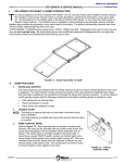
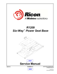
- TABLE OF CONTENTS- FR2SS-SERIES SERVICE MANUAL FEBRUARY 2013 I. INTRODUCTION FOLDOVER RAMP INTRODUCTION his manual applies to the Ricon FoldOver® Stainless Steel Low-Floor Vehicle Access Ramp when installed in transit vehicles. The chapters in this service manual contain a product description, maintenance instructions, and a spare parts list. The descriptions in this chapter apply to the Ricon FoldOver Stainless Steel Low-Floor Vehicle Access Ramp when installed in transit vehicles. The FoldOver ramp is installed in transit vehicles to accommodate handicapped passengers who cannot easily climb steps or are using mobility-aid equipment. The hydraulically powered ramp folds into the vehicle vestibule flooring when not in use. All FR2SS-series ramps have a 660-lb (300kg) load limit. Passengers must use the ramp one at a time; do not overload ramp. Be certain that passenger mobility-aid equipment fits between the left- and right-side ramp barriers without any interference before allowing use of ramp. T FIGURE 1-1: RICON FOLDOVER RAMP A. RAMP FEATURES 1. INTERLOCK SUPPORT The ramp electronics can interface with the vehicle interlock circuitry to prevent vehicle departure when ramp is deployed. The ramp interlock circuitry senses the position of the ramp (stowed or deployed) and makes this information available at the J1 bus harness connector. A vehicle interlock circuit typically requires that the following conditions be met before operating power is supplied to ramp: Park vehicle and set parking brake. Place transmission in neutral. Open vehicle door adjacent to ramp. 2. AUDIBLE ALERT NOTE: This feature is optional and may not have been connected during ramp installation. The ramp supports an audible alert device that sounds while the ramp is in motion. 3. RAMP CONTROL PANEL Refer to Figure 2-2. Ricon typically does not provide a control panel. However, the ramp can be operated with one similar to that shown (the actual panel appearance will vary between transit authorities and vehicles). The control panel is normally installed in the driver area. It should have a power ON/OFF switch, a power on indicator light, and a springloaded, three-position ramp control switch (center-off). The ramp receives power from the vehicle when the interlock conditions are met and the power on/off switch is ON. The control panel can then be used to transmit deploy or stow signals to the ramp hydraulic system. FIGURE 2-2: TYPICAL CONTROL PANEL 32DFR108.B.4 1-1 INTRODUCTION B. FR2SS-SERIES SERVICE MANUAL FEBRUARY 2013 RICON PRODUCT SUPPORT If you have questions about this manual, or you need additional copies, please contact Ricon Product Support at the locations listed. Also, refer to the Ricon website at: www.riconcorp.com Ricon Corporation 7900 Nelson Road Panorama City, CA 91402......................................................................................................... (818) 267-3000 Outside (818) Area Code .......................................................................................................... (800) 322-2884 Website .............................................................................................................................www.riconcorp.com Vapor Ricon Europe Ltd. Meadow Lane Loughborough, Leicestershire ....................................................................................0044 (9) 1509 635 920 LE 1HS United Kingdom Website ................................................................................................................................ www.riconuk.com C. RICON TWO-YEAR LIMITED WARRANTY The following warranty provides two years of limited coverage for the Ricon FoldOver Stainless Steel Low-Floor Vehicle Access Ramp. 1-2 32DFR108.B.4 FR2SS-SERIES SERVICE MANUAL FEBRUARY 2013 INTRODUCTION RICON FOLDOVER RAMP TWO-YEAR LIMITED WARRANTY Ricon Corporation (Ricon) warrants to the original purchaser of this product that Ricon will repair or replace, at its option, any parts that fail because of defective material or workmanship as follows: Repair or replace parts for a period of two years starting from the date ramp is put into service. Obtain a complete list of parts covered by this warranty from Ricon Product Support. Labor costs for specified parts replaced under this warranty for a period of two years from the date put into service. A Ricon rate schedule determines parts covered and labor allowed. This Warranty Does Not Cover: Malfunction or damage of product parts caused by accident, misuse, lack of proper maintenance, neglect, improper adjustment, modification, alteration, mechanical condition of vehicle, road hazards, overloading, failure to follow operating instructions, or acts of nature (i.e., weather, lightning, flood). NOTE: Ricon recommends this product be inspected by an authorized Ricon dealer or qualified service technician at least once every six months, or sooner if necessary. Perform required maintenance at this time. WARNING! THIS PRODUCT HAS BEEN DESIGNED AND MANUFACTURED TO EXACT SPECIFICATIONS. ANY MODIFICATION OF THIS PRODUCT CAN BE HAZARDOUS. This Warranty is Void If: The product is not installed and maintained by an authorized Ricon dealer or qualified service technician. The product is modified, in any respect from its original design, without written authorization from Ricon. Ricon disclaims liability for any personal injury or property damage that results from operation or use of a Ricon product that is modified from the original Ricon design. No person or company is authorized to change the design of this Ricon product without written authorization from Ricon. Ricon obligation under this warranty is exclusively limited to the repair or exchange of parts that fail within the applicable warranty period. Ricon assumes no responsibility for expenses or damages, including incidental or consequential damages. Some states do not allow the exclusion or limitation of incidental or consequential damages, so the above limitation or exclusion may not apply. Important: The warranty registration card must be completed and returned to Ricon within 20 days after product installation to validate this warranty. The warranty is not transferable. The warranty gives specific legal rights. There may be other rights that vary in each state. 32DFR108.B.4 1-3 INTRODUCTION D. FR2SS-SERIES SERVICE MANUAL FEBRUARY 2013 SHIPPING INFORMATION • When the product is received, unpack the product and check for freight damage. Claims for any damage should be made to the carrier immediately. • Be sure the ramp assembly contains all items listed on the included bill of material. Please report any missing items immediately to Ricon Product Support. Save bill of material for later reference. Return the completed warranty and owner registration cards to Ricon within 20 days to validate warranty. NOTE: The Sales or Service personnel must review the Warranty and this Operator Manual with the user to be certain that they understand how to safely operate the product. Instruct the user to follow the operating instructions without exception. 1-4 32DFR108.B.4 FR2SS-SERIES SERVICE MANUAL FEBRUARY 2013 E. INTRODUCTION CUSTOMER ORIENTATION 1. Figure 2-3 shows major components of the foldover ramp. A description of each component is provided in Table 2-3. Refer to Chapter V “Parts Diagrams and Lists” for more details. HEATER PAD WIRING ACCESS COVER (OPTIONAL) HEATER PAD (OPTIONAL) (LOCATED UNDER NON-SLIP SURFACE) COMPONENT ACCESS COVER NON-SLIP SURFACE FLOOR PLATE FLOW CONTROL VALVES R EA R ELECTRONIC CONTROLLER LE F T SENSOR TARGETS (STOW & DEPLOY) PROXIMITY SENSORS (STOW & DEPLOY) DRIVE ARM DRIVEN ARM ARM HARDWARE RAMP HYDRAULIC PUMP ASSEMBLY DRIVESHAFT HYDRAULIC ACTUATOR MANUAL DEPLOY TOOL (OPTIONAL) HINGE SIDE RAIL R IG H T NON-SLIP SURFACE FRONT MANUAL DEPLOY TOOL SLOT LIFTING STRAP RSM0008000 FIGURE 2-3: FR2SS-SERIES MAJOR RAMP COMPONENTS 32DFR108.B.4 1-5 FR2SS-SERIES SERVICE MANUAL INTRODUCTION FEBRUARY 2013 TABLE 2-3: MAJOR FR2SS FOLDOVER RAMP COMPONENTS NAME Component access cover Electronic controller DESCRIPTION Provides access to ramp hydraulic and electrical components. Translates electrical commands from bus control panel into signals that control ramp hydraulic components. Monitors ramp position and drives counter. Driveshafts (left & right) Transmits actuator torque to drive arms. Drive arms (left &right) Ramp linkage arms attach to outboard end of driveshafts. Driven arms (left & right) Ramp linkage arms attach to ramp. Flow control valves Arm hardware (screws, bushings, thrust washers) Heater mat (optional) Heater mat wiring access cover (optional) Hinge Hydraulic actuator Hydraulic pump assembly Lifting strap Non-slip surfaces Pillow blocks (left & right) Proximity sensors Ramp Side rails (left & right) Manually adjusted valves control rate of ramp motion. Pivoting, load-bearing parts at both ends of driven arms. Bushings and washers are oilite material. Helps keep ramp floor clear of ice and snow. Provides access to wiring for optional heater mat. Pivoting connection between ramp and ramp frame. Hydraulic powered component provides torque used to deploy and stow ramp. Provides hydraulic pressure for use by ramp hydraulic components. The hydraulic pump contains a motor, directional valve, pump assembly, and reservoir. Use to manually deploy or stow ramp. Bonded to ramp to reduce user slippage. Provide support for outer ends of driveshafts. Located near left driveshaft. Detect position of ramp, either stowed or deployed. Unfolds (deploys) to provide access for handicapped passenger use. Folds into vestibule floor (stows) when not used. Vertical curbs help restrict passenger to ramp area. END OF TABLE 1-6 32DFR108.B.4 FR2SS-SERIES SERVICE MANUAL FEBRUARY 2013 F. INTRODUCTION RAMP PART NUMBERS Refer to Table 2-1 for an explanation of FR2SS series ramp part numbers. TABLE 2-1: FR2SS-SERIES RAMP PART NUMBER EXPLANATION FR2SS Location of Electrical Connectors 0 – Rear 1 – Left Side Flooring Trim 0 – Welded 1 – Shipped loose Side barrier trim color 0 – Yellow 1 – None (1 ½” flange) 2 – Black 3 – White Heater 0 – None 1 – Heater (24VDC only) Control Panel 0 – No control panel (internal counter) 1 – Dash panel (w/internal counter) Floor material 0 – Supplied by others 1 – RCA TR-852 Manual Deployment Method 0 – Pull strap 1 – Hook 2 – ¼-turn key 3 – Hatch handle Operating Voltage 0 – 12VDC 1 – 24VDC Ramp Size, W x L 00 – 30” x 48” 01 – 32” x 48” 02 – 32” x 44” 03 – 32” x 43” 04 – 32” x 41” 05 – 30” x 49” (discontinued) 06 – 32” x 50” 07 – 32” x 41” (w/notched rails) 08 – 32” x 32” 09 – 32” x 39” 11 – 32” x 44” 12 – 30” x 44” 13 – 32” x 41” 14 – 32” x 50” 15 – 30” x 45” 16 – 32” x 52” 17 – 30” x 48” 18 – 32” x 48” 32DFR108.B.4 1-7 FR2SS-SERIES SERVICE MANUAL INTRODUCTION FEBRUARY 2013 Refer to Table 2-2 for an explanation of FR2G series ramp part numbers. TABLE 2-2: FR2G -SERIES RAMP PART NUMBER EXPLANATION FR2G Location of Electrical Connectors 0 – Rear 1 – Left Side Flooring Trim 0 – Welded 1 – Shipped loose Side barrier trim color 0 – Yellow 1 – None (1 ½” flange) 2 – Black 3 – White Heater 0 – None 1 – Heater (24VDC only) Control Panel 0 – No control panel (internal counter) 1 – Dash panel (w/internal counter) Floor material 0 – Supplied by others 1 – RCA TR-852 Manual Deployment Method 0 – Pull strap 1 – Hook 2 – ¼-turn key 3 – Hatch handle Operating Voltage 0 – 12VDC 1 – 24VDC Ramp Size, W x L 00 – 30” X 48” 01 – 32” x 48” 02 – 32” x 44” 03 – 32” x 43” 04 – 32” x 41” 05 – 30” x 48” (GILLIG) 06 – 32” x 50” 07 – 32” x 41” (w/notched rails) 1-8 32DFR108.B.4 FR2SS-SERIES SERVICE MANUAL FEBRUARY 2013 INTRODUCTION Refer to Table 2-3 for an explanation of FR2N series ramp part numbers. TABLE 2-2: FR2N -SERIES RAMP PART NUMBER EXPLANATION FR2N Location of Electrical Connectors 0 – Open Fluid Levor Sensor 0 – No 1 – Yes Side barrier trim color 0 – Black 1 – Yellow Heater 0 – None 1 – Heater (24VDC only) Control Panel 0 – No control panel 1 – Dash panel Floor material 0 – Supplied by others 1 – RCA, Ribbed, TR-452 2 – Altro Chroma 2731/SCR Yel Nose 3 – Altro Chroma CE27MTS/SCR Yel Nose 4 – Tarabus, w/Welcome Logo 5 – Altro, TFCR 2761/SCR Yel Nose 6 – Altro, TFCR 2772/SCR Yel Nose 7 – Tarabus,NT Helios 8805 8 – Altro, Meta, Midnite Yel Nose 9 – Altro Chroma 2702/SCR Yel Nose Manual Deployment Method 0 – Pull strap 1 – Hook 2 – Hatch handle Operating Voltage 0 – 12VDC 1 – 24VDC Ramp Size, W x L 01 – 30” X 48” 32DFR108.B.4 1-9 INTRODUCTION FR2SS-SERIES SERVICE MANUAL FEBRUARY 2013 This page intentionally left blank. -BACK TO TOP- 1 - 10 -PRINT CHAPTER- - NEXT CHAPTER32DFR108.B.4