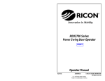
1
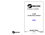
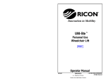
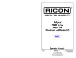
Innovation in Mobility FOLDOVER RAMP Low-Floor Vehicle Access Ramp for GILLIG PRINT OPERATOR MANUAL 08/27/99 32DFR103.A 95-2002 RICON CORPORATION All Rights Reserved U.S and Foreign Patent(s) Pending Printed in the United States of America THIS RICON PRODUCT MUST BE SERVICED BY AUTHORIZED RICON SERVICE TECHNICIANS. PRODUCT USERS MUST REFER TO THIS MANUAL FOR OPERATING AND GENERAL MAINTENANCE INSTRUCTIONS. RETAIN THIS MANUAL IN THE VEHICLE FOR FUTURE REFERENCE. Customer Name: Installing Dealer: Date Installed: Serial Number: -i- REVISION RECORD - ii - REVISION PAGE(S) DESCRIPTION OF CHANGE ECR/ECO 32DFR103.A ALL Initial Release N/A TABLE OF CONTENTS Chapter I. Page INTRODUCTION .................................................................................................................. 1-1 RICON ONE-YEAR LIMITED WARRANTY .................................................................................. 1-2 II. III. IV. DESCRIPTION ..................................................................................................................... 2-1 A. RAMP FEATURES .......................................................................................................... 2-1 B. RAMP LOAD CLEARANCE AND CAPACITY ...................................................................... 2-2 C. MAJOR COMPONENTS .................................................................................................. 2-2 D. RAMP DECALS .............................................................................................................. 2-4 OPERATING INSTRUCTIONS ............................................................................................ 3-1 A. SAFETY PRECAUTIONS .................................................................................................. 3-1 B. DAILY INSPECTION......................................................................................................... 3-2 C. RAMP OPERATION......................................................................................................... 3-3 MAINTENANCE INSTRUCTIONS ....................................................................................... 4-1 LIST OF FIGURES Figure Page 2-1 FOLDOVER RAMP .................................................................................................................. 2-1 2-2 TYPICAL RAMP CONTROLLER ................................................................................................ 2-1 2-3 MAJOR RAMP COMPONENTS................................................................................................. 2-2 2-4 DECAL LOCATIONS ................................................................................................................ 2-4 3-1 PARKING DANGER ................................................................................................................. 3-1 3-2 RAMP MIDPOINT (DURING DEPLOY)....................................................................................... 3-4 3-3 RAMP MIDPOINT (DURING STOW).......................................................................................... 3-4 3-4 RAMP MIDPOINT (DURING DEPLOY)....................................................................................... 3-5 3-5 RAMP MIDPOINT (DURING STOW).......................................................................................... 3-6 LIST OF TABLES Table Page 2-1 MAJOR RAMP COMPONENTS................................................................................................. 2-3 3-1 DAILY INSPECTION................................................................................................................. 3-2 4-1 MAINTENANCE SCHEDULE ..................................................................................................... 4-1 - iii - I. INTRODUCTION T his document provides operation instructions for the Ricon FoldOver Ramp installed in Gillig transit vehicles. If there are questions about this manual, or you need additional copies, please contact the Ricon Product Support Department at one of the following locations: Ricon Corporation 7900 Nelson Road Panorama City, CA 91402 Telephone: ........................................ (818) 267-3000 ........................................ (800) 322-2884 (outside 818 area code) Ricon U.K. Ltd. Littlemoss Business Park, Littlemoss Road Droylsden, Manchester United Kingdom, M43 7EF Telephone: ........................................ (+44) 161 301 6000 Ricon Scandinavia A/S Stanseveien 27 N-0976 Oslo Norway Telephone: ........................................ (+47) 22 16 70 90 World Wide Website: www.riconcorp.com 1-1 RICON ONE-YEAR LIMITED WARRANTY Ricon Corporation (Ricon) warrants to the original purchaser of this product that Ricon will repair or replace, at its option, any parts that fail because of defective material or workmanship as follows: • Repair or replace parts for a period of one (1) year starting from the date of purchase. A complete list of parts covered by this warranty can be obtained from an authorized Ricon dealer. • Labor costs for specified parts replaced under this warranty for a period of one (1) year from date put into service. A Ricon rate schedule determines parts covered and labor allowed. If You Need to Return a Product: Return this Ricon product to Ricon Corporation. Please give as much advance notice as possible and allow a reasonable amount of time for repair. This Warranty Does Not Cover: • Labor or service charges. • Malfunction or damage to product parts caused by accident, misuse, lack of proper maintenance, neglect, improper adjustment, modification, alteration, the mechanical condition of the vehicle, road hazards, overloading, failure to follow operating instructions, or acts of Nature (i.e., weather, lightning, flood, etc.). NOTE: Ricon recommends that this product be inspected by an authorized Ricon dealer at least once every six months or sooner if necessary. Any required maintenance or repair should be performed at that time. WARNING THIS PRODUCT HAS BEEN DESIGNED AND MANUFACTURED TO EXACT SPECIFICATIONS. ANY MODIFICATION OF THIS PRODUCT CAN BE DANGEROUS. This Warranty is Void If: • The product has been installed or maintained by someone other than an authorized Ricon dealer. • The product has been modified or altered in any respect from its original design without written authorization by Ricon. Ricon disclaims liability for any personal injury or property damage that results from operation of a Ricon product that has been modified from the original Ricon design. No person or company is authorized to change the design of this Ricon Product without written authorization by Ricon. Ricon's obligation under this warranty is exclusively limited to the repair or exchange of parts that fail within the applicable warranty period. Ricon assumes no responsibility for expenses or damages, including incidental or consequential damages. Some states do not allow the exclusion or limitation of incidental or consequential damages, so the above limitation or exclusion may not apply. Important: The warranty registration card must be completed and returned to Ricon within twenty (20) days after installation of this Ricon product for the warranty to be valid. The warranty is not transferable. The warranty gives specific legal rights. There may be other rights that vary in each state. 1-2 II. DESCRIPTION T he hydraulically powered RICON FoldOver Ramp accommodates passengers using mobility-aided equipment or passengers that cannot climb steps to board and exit the vehicle. The ramp folds away into the vestibule flooring. A. RAMP FEATURES 1. INTERLOCK SUPPORT The ramp electrical circuitry interfaces with the vehicle interlock circuitry to prevent accidental vehicle departure when the ramp is deployed. The ramp interlock circuitry senses the position of the ramp, stowed or deployed, and makes this information Figure [2-1]: FoldOver Ramp available at the J1 bus harness connector. The vehicle interlock circuit normally requires all the following conditions be met before power is made available for ramp operation: 2. a. vehicle must be parked with the parking brake set. b. transmission must be in park/neutral. c. vehicle door adjacent to the ramp must be open. AUDIBLE ALERT The ramp is designed with an audible alert that activates while the ramp is in motion. (This is an optional feature and may or may not have been connected during ramp installation on the vehicle.) 3. RAMP CONTROL PANEL INTERFACE The ramp is designed to operate with a control panel similar to that shown in Figure [2-2]. It is normally installed in the driver area of the vehicle. The ramp control panel will typically have a power on/off switch, a power on indicator light and a three position ramp control switch. The ramp receives power from the vehicle when the power on/off switch is activated and the interlock conditions are met. The control panel can then transmit deploy or stow signals to the ramp hydraulic system. Figure [2-2]: Typical Control Panel 2-1 4. RAMP LOAD CLEARANCE AND CAPACITY The ramp is to be used by one passenger at a time; do not overload the ramp. Before allowing passengers to use the ramp, make sure that the passenger’s mobility aid equipment fits safely between the left and right side barriers of the ramp Load Limit:................................. 600 lb (272 kg) Load Clearance: Width: .................................... 30.2 inches (76.7 cm) Length:................................... 48.9 inches (124.2 cm) B. MAJOR COMPONENTS The major components of the fold out ramp are shown in Figure [2-3]. A description of each of the components is provided in Table [2-1]. Figure [2-3]: Major Ramp Components 2-2 Table [2-1]: Major Ramp Components Item Name Description [1] Ramp Platform that folds out (deploys) or folds in (stows) to assist a passenger on and off the vehicle. [2] Non-Skid Flooring Attached to the ramp platform surface to prevent slippage. [3] Actuator Hydraulically powered component that provides the rotary motion that deploys and stows the ramp. [4] Drive Arms (Left & Right) [5] Hardware (Shoulder Bolts, Bushings, Thrust Washers) Pivoting, load bearing surfaces at ends of ramp arms. Bushings and washers are oilite material. [6] Driven Arms (Left & Right) Ramp linkage arms attached to the ramp, and driven by the actuator arms. [7] Flow Control Valves Manually adjusted needle valves that control rate of ramp movement. [8] Controller Receives DEPLOY and STOW commands from ramp control panel and translates these commands into signals that control the ramp hydraulic components. [9] Lifting Strap [10] Side Barriers (Left & Right) Vertical curbs that help confine users to the ramp during boarding and exiting. [11] Directional Valves Hydraulic components that control deploy and stow actions. [12] Proximity Sensors Electrical sensors that translate ramp position; connected to control box. Ramp linkage arms driven by the actuator. Used to manually deploy or stow the ramp. 2-3 C. RAMP DECALS Refer to Figure [2-4]. Check the condition of all decals. Inspect for chipping, peeling, fading and illegibility. Do the inspections at the intervals recommended in Table [41]. Replace the decals as necessary, in the locations shown. If it is necessary to replace damaged decals, order part number shown in Figure [2-4]. (MADE FROM P/N 32-10-166) (MADE FROM P/N 32-10-166) PATENT P/N 32-10-171 (Located on outside of vehicle.) STAND CLEAR, CAUTION 2-4.dwg Figure [2-4]: Decal Locations 2-4 III. OPERATING INSTRUCTIONS Thoroughly read these instructions before operating the RICON FoldOver ramp. A. SAFETY PRECAUTIONS The following safety precautions must be observed: • Perform the daily safety check as specified in Table [3-1] (refer to paragraph B in this section). • Refer to Figure [3-1]. Do not use the ramp on sloped or steeply crowned roadways. Use of the ramp on these inclined surfaces is dangerous and compromises passenger safety. • Before you deploy or stow the ramp, check the area near the ramp for objects that could interfere with ramp operation. Do not operate the ramp until you check these areas and ensure it is safe to proceed. NOTE DO NOT DEPLOY RAMP IF VEHICLE IS NOT ONLEVEL GROUND • Inspect the ramp before loading passengers. Do not use the ramp if it is unsafe to do so, or if unusual noises or movements are present. • The ramp is designed for use by one passenger at a time (with or without mobility equipment). Do not allow passengers to exceed the ramp’s load capacity of 600lbs (272kgs). • Before allowing passengers to board or exit the vehicle using the ramp, make sure that the passengers and their mobility equipment fit safely between the left and right side barriers of the ramp. • Keep others at a safe distance while operating the ramp. • Caution all passengers to use extreme care during wet conditions; shoes, wheels, brakes, etc. are susceptible to slippage on the ramp. • Do not place your arms or legs in or near any moving parts of the ramp. • As the ramp operator, always supervise the use of the ramp. Make sure the passengers using the ramp board and exit the vehicle slowly and carefully. • For equipment and personal safety reasons, do not allow any persons to play, sit, or rest on or near the ramp. • Passengers using mobility equipment (e.g., wheelchairs and scooters) must travel forward on ramp and board and exit the vehicle slowly and carefully. • Do not leave the ramp unattended after ramp deployment. Retract the ramp to its stowed position after use. Figure [3-1]: Parking Danger 3-1 B. DAILY INSPECTION Check the ramp on a daily basis before operation, following the Daily Inspection outlined in Table [3-1]. Do not operate the ramp if any of the conditions are not met. Table [3-1]: Daily Inspection Inspection Point Ramp Controller Check 1. The Power ON/OFF switch operates correctly. 2. The Power On Indicator illuminates when the power ON/OFF switch is ON. 3. The DEPLOY and STOW switches operate correctly. 4. Investigate irregular noises or movements that occur when the ramp deploys or stows. Ramp and Surrounding Area 1. Make sure there are no foreign objects in the stepwell area of the vehicle, or amidst the actuator arms. Ramp Flooring 1. Make sure the surfaces are clean and free of any slippery or sticky substances that may compromise the safety of the ramp users and/or their mobility equipment. 2. Make sure the non-skid flooring is secure and its corners are not peeling from the ramp surface. 3-2 C. RAMP OPERATION WARNING IMPROPER USE OF THE RAMP CAN RESULT IN PERSONAL INJURY. OPERATORS MUST READ AND FOLLOW THE OPERATING INSTRUCTIONS IN THIS MANUAL. ADDITIONAL COPIES OF THIS MANUAL ARE AVAILABLE FROM: RICON CORPORATION 7900 NELSON ROAD PANORAMA CITY, CA 91402 (800) 322-2884 OR (818) 267-3000 2) PRIOR TO USE, INSPECT RAMP AND OTHER RAMP COMPONENTS FOR PROPER FUNCTION, REQUIRED MAINTENANCE OR DAMAGE. IF A PROBLEM EXISTS, DO NOT USE AND SEEK AN AUTHORIZED DEALER FOR REPAIR. 3) DO NOT EXCEED RAMP LOAD CAPACITY OF 600 POUNDS (272 KILOGRAMS). 4) THE RAMP IS DESIGNED FOR USE BY THOSE WHO CANNOT CLIMB STEPS AND FOR PEOPLE ON MOBILITY-AID EQUIPMENT (I.E., WHEELCHAIRS & WALKERS). RICON CORPORATION DISCLAIMS LIABILITY FOR DAMAGE OR PERSONAL INJURY RESULTING FROM IMPROPER INSTALLATION, MODIFICATION TO THE RAMP OR OTHER COMPONENTS, LACK OF MAINTENANCE OR REPAIR, NEGLIGENCE, ABUSE OR FAILURE TO FOLLOW THE OPERATING INSTRUCTIONS. • Do the daily safety check described in Table [3-1] before putting the vehicle into service. If a problem exists, do not use the ramp and seek an authorized dealer for repair. • Adhere to the Safety Precautions at the beginning of this chapter. • The transmission and brakes are temporarily disabled while the ramp is deployed. Operation is restored after the ramp is fully stowed. 1. OPERATING THE RAMP WITH THE CONTROL PANEL a. Vehicle Preparation (1) Stop the vehicle, and if applicable, lower the vehicle. (2) Set the vehicle parking brake. (3) Put the transmission in park/neutral and open the vehicle door. NOTE: The ramp can be deployed only after the parking brake is set, the transmission is in park/neutral and the vehicle door is open. (4) Caution people inside and outside of the vehicle to clear the area and that the ramp is about to deploy. 3-3 b. Ramp Deployment WARNING BEFORE OPERATING, MAKE SURE PEOPLE ARE A SAFE DISTANCE FROM THE RAMP AREA. (1) On the ramp control panel, actuate the power switch to apply power to the ramp; the power on indicator should illuminate. (2) Toggle the ramp control switch to the DEPLOY setting. Hold the switch in DEPLOY until the ramp passes its midpoint (vertical position; refer to Figure [3-2]), then release the switch. After the ramp reaches midpoint it will lower to the ground without assistance. NOTE: The audible alert, if connected, will sound while the ramp is in motion. Figure [3-2]: Ramp Midpoint (during deploy) (3) The movement of the ramp can be reversed at any time during its travel. To reverse the direction of the ramp while it is moving, toggle the control switch to the opposite setting (from DEPLOY to STOW, or from STOW to DEPLOY). (4) Passengers must enter or exit vehicle one at a time. Passengers using mobility equipment (e.g., wheelchairs and scooters) must travel forward on ramp. c. Ramp Stowage WARNING BEFORE OPERATING, MAKE SURE PEOPLE ARE A SAFE DISTANCE FROM THE RAMP AREA. (1) Toggle the control switch to the STOW setting. Hold the switch in the STOW setting until the ramp passes its midpoint (see Figure [3-3]), then release the switch. After the ramp passes this midpoint, it will fold down to the stowed position in the stepwell without assistance. NOTE: If connected, the audible alert will sound while ramp is in motion. (2) Be certain the ramp is fully stowed before you try to move the vehicle. 3-4 Figure [3-3]: Ramp Midpoint (during stow) (3) Close the vehicle door. (4) Raise the vehicle, if applicable. 2. MANUAL RAMP OPERATION a. Manual Ramp Deployment (1) Stop the vehicle in a safe area. Lower vehicle, if possible. (2) Set the vehicle parking brake. (3) Put the transmission in park/neutral and open the vehicle door. WARNING COMPLY WITH SAFETY PRECAUTIONS AT BEGINNING OF THIS CHAPTER. (4) Locate the strap on the edge of the ramp (refer to Figure [2-3]). WARNING AVOID PINCHING YOUR FINGERS WHEN MANUALLY LIFTING RAMP. (5) Use the strap to lift the ramp to obtain a handhold on the front edge. CAUTION Do not use excessive force to lift the ramp. (6) Grasp the front edge of the ramp with both hands. Unfold the ramp from its stowed position while keeping your back vertical and legs together. (7) Release the ramp after it passes its midpoint (refer to Figure [3-4]) and it will continue to unfold without assistance. (8) Load/unload passengers. Passengers using mobility equipment must travel forward on ramp. Figure [3-4]: Ramp Midpoint (during deploy) 3-5 b. Manual Ramp Stowage (1) Make sure people are a safe distance from the ramp area before stowing the ramp. CAUTION Do not use excessive force to lift the ramp. (2) Refer to Figure [2-3]. Use the strap on the front edge of the ramp to lift it up until you can gain a convenient grip with two hands. Release the ramp after it passes its midpoint (refer to Figure [35]) and it will continue to fold without assistance NOTE: Be certain the ramp is fully stowed before attempting to move the vehicle. Figure [3-5]: Ramp Midpoint (during stow) 3-6 IV. MAINTENANCE INSTRUCTIONS R A. egular maintenance and safety inspections of the RICON FoldOver Ramp will provide optimum performance and reduce the need for repairs. ADDITIONAL MAINTENANCE INFORMATION Additional maintenance information is available in the FoldOver Ramp Service manual, part number 32DFR104. This manual is available from Ricon in printed hard copy, or at the Ricon website in PDF format. The website is located at www.riconcorp.com. Click on RICON CORPORATION and then DEALER’S ROOM at the website. Entry to the dealer’s room will require a Dealer Number and a Password. B. MAINTENANCE SCHEDULE Maintain the ramp as described in Table [4-1]. Under conditions of heavy use (in excess of 20 cycles per day), maintenance of the ramp should be performed more frequently. Modification to the ramp or failing to properly maintain the ramp will void the warranty and may result in unsafe operating conditions. CAUTION This Ricon product is highly specialized. Maintenance and repairs must be performed by a Ricon dealer using Ricon replacement parts. Modification or improper maintenance of this product will void warranty and may result in unsafe ramp operating conditions. Table [4-1]: Maintenance Schedule Inspection Point Action – 6000 MILE SAFETY CHECK – Hydraulic Fluid Leaks Check all hoses and fittings; tighten or replace as necessary. Setscrews Check for loose or missing setscrews at these locations: • Driveshaft couplings (2 x 2 ea) • Sensor Target (2 ea) • Ramp/Actuator arms (2 x 3 per side) • Pillow blocks (2 x 2 ea) Tighten and/or apply thread-locker (Loc-tite), as necessary. Actuator Arm Screws Check for loose shoulder screws; retighten the screws as necessary. Ramp Interior (for Debris) Check the ramp interior area for accumulated dirt and debris. Remove if found. (continued) 4-1 Inspection Point Action Non-Slip Flooring Visually check for damaged surfaces, and loose or missing hardware. Decals Visually check for damage or poor attachment. – 12,000 MILE SAFETY CHECK – Wiring Harnesses Check wiring for abrasions and connectors for looseness; replace as necessary. Fasteners Check all threaded fasteners for tightness and retighten as necessary. Non-skid Surfaces Check non-skid flooring for excessive wear or damage (rips, tears, peeling, etc.) and replace as necessary. – 24,000 MILE SAFETY CHECK – Pillow Block (Lubrication) Lightly grease pillow blocks (note that they are sealed). Bushing & Thrust Washer Wear Refer to Figure [2-3] and Table [2-1]. Check these parts for excessive play and replace if necessary. 4-2