1
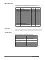
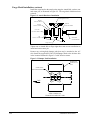
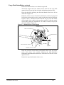
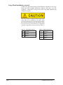
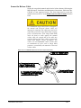
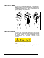
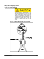
3,600 Pound Keeperless Cargo Hook Kit For The MD Helicopters’ 369 Series, 500N, and 600N Models System Part Numbers 200-264-01, 200-264-02 Owner's Manual Owner's Manual Number 120-096-01 Revision 0 August 4, 2008 13915 NW 3rd Court Vancouver Washington 98685 USA Phone: 360-546-3072 Fax: 360-546-3073 Toll Free: 800-275-0883 www.OnboardSystems.com This page intentionally left blank. Record of Revisions Revision Date Page(s) 0 08/04/08 All Reason for Revision Initial Release Register Your Products for Automatic Notifications Onboard Systems offers a free notification service via fax or email for product alerts and documentation updates. By registering your Onboard Systems products at our website, we will be able to contact you if a service bulletin is issued, or if the documentation is updated. You can choose to receive notices on an immediate, weekly, or monthly schedule via fax, email or both methods. There is no charge for this service. Please visit our website at www.onboardsystems.com/notify.php to get started. ii This page intentionally left blank. CONTENTS Section 1 General Information Introduction, 1-1 Warnings, Cautions and Notes, 1-1 Bill of Materials, 1-2 Inspection, 1-2 Specifications, 1-2 Theory of Operation, 1-3 Section 2 Installation Instructions Cargo Hook Removal, 2-1 Cargo Hook Installation, 2-1 Secure the Release Cables, 2-5 Installation Check-Out, 2-6 Component Weights, 2-6 Cargo Hook Location, 2-6 Paper Work, 2-6 Section 3 Operation Instructions Operating Procedures, 3-1 Cargo Hook Loading, 3-2 Cargo Hook Rigging, 3-2 Section 4 Maintenance Inspection, 4-1 Instructions for Returning a System to the Factory, 4-2 Section 5 Certification FAA STC, 5-1 Canadian Approval, 5-3 EASA STC, 5-4 iii CONTENTS, continued Figures 2-1 2-2 2-3 2-4 2-5 3-1 3-2 Travel Limit Bumper Installation, 2-1 Attach Hardware Installation, 2-2 Bumper Pads, 2-2 Manual Release Cable Rig, 2-3 Un-commanded Release From Incorrectly Secured Cable, 2-5 Cargo Hook Loading, 3-2 Examples of Recommended Cargo Hook Rigging, 3-3 1-1 2-1 2-2 2-3 2-4 4-1 Specifications, 1-2 Cargo Hook Connector, 2-4 Bulkhead Receptacle, 2-4 Component Weight, 2-6 Cargo Hook Location, 2-6 Inspection, 4-1 Tables iv Section 1 General Information Introduction The 200-264-01 cargo hook kit is approved for installation with the following MD Helicopter models which use the 369H92105-501 cargo hook assembly. 369D 369HS 369E 369HM 369F 369HE 369FF 500N The 528-029-00 Cargo Hook, 270-073-00 Electrical Release Cable, and 268-005-01 Manual Release Cable included in this 200-264-01 cargo hook kit are suitable as replacements for the cargo hook (Breeze-Eastern P/N 17149-4), electrical release cable, and manual release cable in the MD Helicopters’ 369H92105-501 cargo hook assembly. The 200-264-02 cargo hook kit is approved for installation with MD Helicopter 600N models which use the 369H92105-503 or 369H92105-505 cargo hook assembly. Warnings, Cautions and Notes The following definitions apply to Warnings, Cautions and Notes used in this manual. Means that if this information is not observed, serious injury, death or immediate loss of flight safety could occur. Means that there is a risk of injury or degradation in performance of equipment if this information is not observed. Draws the reader’s attention to information which may not be directly related to safety, but which is important or unusual. General Information 1-1 Bill of Materials The following items are included with the Cargo Hook Kit, if shortages are found contact the company from whom the system was purchased. Part No. Description 528-029-00 270-073-00 270-073-02 268-005-01 268-005-02 290-360-01 290-361-00 510-178-00 510-170-00 510-174-00 510-183-00 290-332-00 120-096-01 121-006-01 122-017-00 123-003-01 Cargo Hook Electrical Release Harness Electrical Release Harness Manual Release Cable Manual Release Cable Travel Limit Bumper Bumper Pads Cotter Pin Nut Washer Washer Attach Bolt Owner’s Manual RFM Supplement Cargo Hook Service Manual ICA Maintenance Manual 200-264-01 Quantity 200-264-02 Quantity 1 1 1 1 2 1 1 1 2 1 1 1 1 1 1 1 1 1 2 1 1 1 2 1 1 1 1 1 Inspection Inspect the cargo hook for evidence of damage, corrosion and security of lock wire and fasteners. If damage is evident, do not use the unit until it has been repaired. Specifications Table 1-1 Specifications (528-029-00 Cargo Hook) Design load 3,600 lbs. (1,633 kg.) Design ultimate strength 13,500 lbs. (6,123 kg.) Electrical release capacity 9,000 lbs. (4,082 kg.) Mechanical release capacity 9,000 lbs. (4,082 kg.) Force required for mechanical 8 lb. Max.(.600” travel) release at 3,600 lb. Electrical requirements 22-32 VDC, 6.9 - 10 amps Minimum release load 0 pounds Unit weight 3.0 lbs. (1.4 kg.) Mating electrical connector PC06P8-2S 1-2 General Information Theory of Operation The primary elements of the Cargo Hook are the load beam, the internal mechanism, and a DC solenoid. The load beam supports the load and is latched through the internal mechanism. The DC solenoid and an external manual release cable provide the means for unlatching the load beam. The load is attached to the load beam by passing the cargo sling ring into the throat of the load beam and pushing the ring against the upper portion of the load beam throat, which will initiate the hook to close. In the closed position, a latch engages the load beam and latches it in this position. To release the load, the latch is disengaged from the load beam. With the latch disengaged, the weight of the load causes the load beam to swing to its open position, and the cargo sling slides off the load beam. The load beam then remains in the open position awaiting the next load. A load release can be initiated by three different methods. Normal release is achieved by pilot actuation of the push-button switch in the cockpit. When the push-button switch is pressed, it energizes the DC solenoid in the Cargo Hook, and the solenoid opens the latch in the internal mechanism. In an emergency, release can be achieved by operating a mechanical release cable. The release cable operates the internal mechanism of the Cargo Hook to unlatch the load beam. The load can also be released by the actuation of a lever located on the side of the Cargo Hook. General Information 1-3 This page intentionally left blank. Section 2 Installation Instructions These procedures are provided for the benefit of experienced aircraft maintenance facilities capable of carrying out the procedures. They must not be attempted by those lacking the necessary expertise. Cargo Hook Removal If present, remove the MD Helicopters’ supplied Cargo Hook from the aircraft by disconnecting the electrical release cable from the belly mounted bulk-head type connector. Disconnect the manual release cable from the cyclic stick release lever assembly and remove it from the attaching clamps along its entire length. Remove the single bolt used to attach the Cargo Hook to the airframe mounting bracket and separate the Cargo Hook from the aircraft. Cargo Hook Installation Inspect the helicopter’s cargo hook attach point and attaching hardware to ensure that all components are in serviceable condition. Install the P/N 290-360-01 travel limit bumper to the Cargo Hook as illustrated in Figure 2-1. The Travel Limit Bumper helps protect the aircraft skin and the release cables from excessive hook movement. Do not use the cargo hook without the travel limit bumper in place. Figure 2-1 Travel Limit Bumper Installation Installation Instructions 2-1 Cargo Hook Installation, continued Install the cargo hook to the attach point using the Attach Bolt, washers, nut and cotter pin, as illustrated in Figure 2-2. The cargo hook load beam must point aft. Figure 2-2 Attach Hardware Installation Existing Attach Point Washer P/N 510-183-00 Washer P/N 510-183-00 Washer P/N 510-174-00 Cotter Pin P/N 510-178-00 Nut P/N 510-170-00 Attach Bolt P/N 290-332-00 Cargo Hook Tighten nut on Attach Bolt to finger tight then rotate to next castellation to install and secure cotter pin. Remove any existing hook bumper pads that may be attached to the A/C skin. Install the supplied P/N 290-361-00 Bumper Pads to the airframe skin in the location illustrated in Figure 2-3 with 3M trim cement. Figure 2-3 Bumper Pads Installation BUMPER PAD P/N 290-361-00 QTY 2 CARGO HOOK MOUNTING BRACKET 1.50 1.50 FWD VIEW LOOKING UP FROM BELOW AIRCRAFT SKIN 2-2 Installation Instructions Cargo Hook Installation, continued Remove the manual release cover from the cargo hook. Thread the swaged end of the manual release cable into the cargo hook manual release boss on the hook side plate and tighten against the hook. Place the cable ball end fitting into the hook manual release lever fork as illustrated in Figure 2-4. Rotate the release lever in the clockwise direction to remove free play and hold in this position (the free play is taken up when the hook lock indicator begins to move). Measure the cable ball end free play with the manual release handle in the cockpit in the non-release position. Adjust the manual release cable system for a minimum of .125 inches (3.2 mm) of free play at the fork as shown in Figure 2-4. Figure 2-4 Manual Release Cable Rigging Release Lever Hook Lock Indicator Cable Ball End Manual Release Cable .125" MIN. Release Lever Fork Route the electrical release harness and manual release cable and rig the cyclic stick release lever assembly following the MD Helicopters Installation and Maintenance Instructions, Publication No CSP-005 or later approved source. Replace the cargo hook manual release cover. Installation Instructions 2-3 Cargo Hook Installation, continued Connect the cargo hook electrical release harness connector to the Cargo Hook and belly mounted bulk-head receptacle and safety wire the connector. Listed below is the pin out for the cargo hook connector and bulkhead receptacle. The Cargo Hook is equipped with a suppression diode that will be damaged if the Cargo Hook electrical connections are reversed. Do not attach the electrical connector until the polarity of the aircraft connector is determined to be compatible with the Cargo Hook connector listed in Table 21. Table 2-1 Cargo Hook Connector 2-4 Table 2-2 Bulkhead Receptacle Pin Function Pin Function A Ground A Power B Positive B Ground C Shield Installation Instructions Secure the Release Cable Secure the cargo hook manual and electrical release harness following the MD Helicopters’ Installation and Maintenance Instructions, Publication No. CSP-005 or later approved source. The first clamp used to secure the manual release to the A/C skin should not be less than 23 inches from the hook. Un-commanded cargo hook release will happen if the manual and electrical release cables are improperly restrained. The cables must not be the stops that prevent the Cargo Hook from swinging freely in all directions. If the Cargo Hook loads cause the hook to strain against the manual release cable the swaged end of the cable may separate allowing the inner cable to activate the cargo hook manual release mechanism. The result is an un-commanded release. Ensure that no combination of cyclic stick or Cargo Hook position is restrained by the manual or electrical release cables. Figure 2-5 Un-commanded Release From Incorrectly Secured Cable Installation Instructions 2-5 Installation Check-Out After installation of the Cargo Hook Kit, perform the following functional checks. 1. Swing the installed Cargo Hook to ensure that the manual release cable assembly and the electrical release harness have enough slack to allow full swing of the suspension assembly without straining or damaging the cables. The cable and harness must not be the stops that prevent the Cargo Hook from swinging freely in all directions. 2. With no load on the cargo hook load beam, pull the lever operated cargo hook mechanical release, the Cargo Hook should release. Reset the cargo hook load beam. 3. Close the cargo hook release circuit breaker and position the battery switch to the ON position. With no load on the cargo hook load beam, depress the cargo hook electrical release button, the Cargo Hook should release. Reset the cargo hook load beam 4. See the MD Helicopters’ service instructions for your specific helicopter model for additional installation instructions. Component Weights The weight of the Cargo Hook Kit components are listed below. Table 2-3 Component Weights Item Cargo Hook Manual Release Cable Electrical Release Cable Bumper Pads Travel Limit Bumper Weight lbs (kgs) 3.0 (1.36) 1.0 (.45) 0.5 (.23) 0.2 (.09) 0.1 (.05) Cargo Hook Location Table 2-4 Cargo Hook Location Fuselage Station 99.3 Paper Work In the US, fill in FAA form 337 for the initial installation. This procedure may vary in different countries. Make the appropriate aircraft log book entry. Insert the Rotorcraft Flight Manual Supplement 121-006-01 in the Rotorcraft Flight Manual. 2-6 Installation Instructions Section 3 Operation Instructions Operating Procedures Prior to each job perform the following: 1. Ensure that the Cargo Hook has been properly installed and that the manual release cable and electrical release harness do not limit the movement of the hook. 2. Be completely familiar with this manual, particularly the Cargo Hook rigging section. 3. Be completely familiar with all MD Helicopters’ cargo hook operating instructions. 4. Activate the electrical system and press the release button to ensure the cargo hook electrical release is operating correctly. The mechanism should operate smoothly. Reset the cargo hook load beam by hand after release. If the load beam does not re-latch do not use the unit until the difficulty is resolved. The release solenoid is intended to be energized only intermittently. Depressing the electrical release button continuously in excess of 20 seconds will cause the release solenoid to overheat, possibly causing permanent damage 5. Activate the release lever assembly located on the cyclic stick to test the cargo hook manual release mechanism. Reset the cargo hook load beam by hand after release. If the load beam does not re-latch do not use the unit until the difficulty is resolved. See the Service Manual 122-017-00 and the MDHC service instructions that cover the original Cargo Hook installation for additional instructions. Operation Instructions 3-1 Cargo Hook Loading The cargo hook can easily be loaded with one hand. A load is attached to the hook by pushing the ring upward against the upper portion of the load beam throat, as illustrated in Figure 3-1, until an internal latch engages the load beam and latches it in the closed position. Figure 3-1 Cargo Hook Loading Cargo Hook Rigging Extreme care must be exercised when rigging a load to the Cargo Hook. Steel load rings are recommended to provide consistent release performance and resistance to fouling. The following illustration shows the recommended rigging, but is not intended to represent all rigging possibilities. Some combinations of small primary rings and large secondary rings could cause fouling during release. It is the responsibility of the operator to assure the cargo hook will function properly with each rigging. 3-2 Operation Instructions Cargo Hook Rigging, continued Nylon Type Straps and Rope Nylon type straps (or similar material) or rope must not be used directly on the cargo hook load beam. If nylon straps or rope must be used they should be first attached to a steel primary ring. Verify that the ring will freely slide off the load beam when it is opened. Only the primary ring should be in contact with the cargo hook load beam Figure 3-2 Examples of Recommended Cargo Hook Rigging Operation Instructions 3-3 This page intentionally left blank. Section 4 Maintenance Refer to Cargo Hook Service Manual 122-017-00 for the cargo hook and Instructions for Continued Airworthiness 123-003-01 for additional detailed maintenance information for the cargo hook kit. Instructions for Returning Equipment to the Factory If an Onboard Systems product must be returned to the factory for any reason (including returns, service, repairs, overhaul, etc) obtain an RMA number before shipping your return. An RMA number is required for all equipment returns. To obtain an RMA, please use one of the listed methods. Contact Technical Support by phone or e-mail ([email protected]). Generate an RMA number at our website: http://www.onboardsystems.com/rma.php After you have obtained the RMA number, please be sure to: Package the component carefully to ensure safe transit. Write the RMA number on the outside of the box or on the mailing label. Include the RMA number and reason for the return on your purchase or work order. Include your name, address, phone and fax number and email (as applicable). Return the components freight, cartage, insurance and customs prepaid to: Onboard Systems 13915 NW 3rd Court Vancouver, Washington 98685 USA Phone: 360-546-3072 Maintenance 4-1 This page intentionally left blank. Section 5 Certification FAA STC Certification 5-1 FAA STC continued 5-2 Certification Canadian Approval Certification 5-3 EASA STC 5-4 Certification EASA STC continued Certification 5-5