1
TCM4/40 operator’s manual
TCM4/40
operator’s
manual
Table of contents
TCM4/40
monitoring
systems
1.
Introduction
2.
What is what
3.
Menu structure and setup programs
4.
Installation and maintenance
5.
Calibration
6.
In vivo monitoring
7.
Troubleshooting
8.
Specifications and ordering information
9.
Functional description
Operator's manual
From software version 3.0
Index
Date of issue
System performance
The procedures described in this manual must be observed in order to ensure proper system
performance, and to avoid hazards.
Radiometer cannot provide or verify system performance characteristics if the system is not installed,
used and maintained in accordance with Radiometer procedures or if accessories not meeting the
specifications provided by Radiometer are used.
Radiometer warrants that the data media on which the software included in the system is furnished is
free from defects in material and workmanship under normal use for three (3) months from the date of
delivery as evidenced by a copy of invoice or receipt.
Third-party software and trademarks
The TCM4/40 monitoring systems comprise the Microsoft® Windows® CE 5.0 program.
By using the system, you accept the terms of the Software License Agreement(s) of the provider(s) of
the above software as shown in the End User License Agreement(s) included in this manual. If you
cannot accept the terms of the Software License Agreement(s), you should not use the system, but
immediately contact your provider for a return of the system and a refund of the purchase price.
Microsoft® and Windows® are trademarks of Microsoft Corporation.
Warranties and disclaimer
Radiometer makes no warranties, express or implied, other than expressly stated.
Any warranties expressly stated in this document are conditional upon the system being installed, used
and maintained in accordance with Radiometer procedures, including that only accessories meeting the
specifications provided by Radiometer are used.
Radiometer disclaims any liability for system performance if the system is not installed, used and
maintained in accordance with Radiometer procedures or if accessories not meeting the specifications
provided by Radiometer are used.
Further, Radiometer disclaims any liability for loss of data and direct, consequential or other damages,
including loss of profit or loss of business, whether such claim for damages is based upon contract,
negligence or tort (including strict liability), and even if Radiometer has knowledge of the possibility of the
potential damage or loss.
Confidentiality
The contents of this document shall not be reproduced or communicated to any third party without the
prior written consent of Radiometer.
Changes
This document is subject to change without notice and you are urged to contact Radiometer to verify
whether the document has been changed.
While every effort is made to ensure the correctness of the information provided in this document as
changed from time to time, Radiometer disclaims any liability for errors and omissions.
Radiometer, the Radiometer logo, ABL, AQT, TCM, RADIANCE, PICO and CLINITUBES are trademarks of Radiometer Medical ApS.
© 2011 Radiometer Medical ApS. All rights reserved.
End user license agreement for Microsoft Software
•
You have acquired a device ("TCM4/40 monitor") that includes software licensed by Radiometer Medical ApS
from Microsoft Licensing Inc. or its affiliates ("MS"). Those installed software products of MS origin, as well as
associated media, printed materials and "online" or electronic documentation ("SOFTWARE") are protected by
international intellectual property laws and treaties. The SOFTWARE is licensed, not sold. All rights reserved.
•
IF YOU DO NOT AGREE TO THIS END USER LICENSE AGREEMENT ("EULA"), DO NOT USE THE DEVICE
OR COPY THE SOFTWARE. INSTEAD, PROMPTLY CONTACT Radiometer Medical ApS FOR INSTRUCTIONS
ON RETURN OF THE UNUSED DEVICE(S) FOR A REFUND. ANY USE OF THE SOFTWARE, INCLUDING BUT
NOT LIMITED TO USE ON THE DEVICE, WILL CONSTITUTE YOUR AGREEMENT TO THIS EULA (OR
RATIFICATION OF ANY PREVIOUS CONSENT).
•
GRANT OF SOFTWARE LICENSE. This EULA grants you the following license:
You may use the SOFTWARE only on the DEVICE.
NOT FAULT TOLERANT. THE SOFTWARE IS NOT FAULT TOLERANT. Radiometer Medical ApS HAS
INDEPENDENTLY DETERMINED HOW TO USE THE SOFTWARE IN THE DEVICE, AND MS HAS RELIED
UPON Radiometer Medical ApS TO CONDUCT SUFFICIENT TESTING TO DETERMINE THAT THE
SOFTWARE IS SUITABLE FOR SUCH USE.
NO WARRANTIES FOR THE SOFTWARE. THE SOFTWARE is provided "AS IS" and with all faults. THE
ENTIRE RISK AS TO SATISFACTORY QUALITY, PERFORMANCE, ACCURACY, AND EFFORT
(INCLUDING LACK OF NEGLIGENCE) IS WITH YOU. ALSO, THERE IS NO WARRANTY AGAINST
INTERFERENCE WITH YOUR ENJOYMENT OF THE SOFTWARE OR AGAINST INFRINGEMENT. IF YOU
HAVE RECEIVED ANY WARRANTIES REGARDING THE DEVICE OR THE SOFTWARE, THOSE
WARRANTIES DO NOT ORIGINATE FROM, AND ARE NOT BINDING ON, MS.
Note on Java Support. The SOFTWARE may contain support for programs written in Java. Java technology is
not fault tolerant and is not designed, manufactured, or intended for use or resale as online control equipment in
hazardous environments requiring fail-safe performance, such as in the operation of nuclear facilities, aircraft
navigation or communication systems, air traffic control, direct life support machines, or weapons systems, in
which the failure of Java technology could lead directly to death, personal injury, or severe physical or
environmental damage. Sun Microsystems, Inc. has contractually obligated MS to make this disclaimer.
No Liability for Certain Damages. EXCEPT AS PROHIBITED BY LAW, MS SHALL HAVE NO LIABILITY FOR
ANY INDIRECT, SPECIAL, CONSEQUENTIAL OR INCIDENTAL DAMAGES ARISING FROM OR IN
CONNECTION WITH THE USE OR PERFORMANCE OF THE SOFTWARE. THIS LIMITATION SHALL
APPLY EVEN IF ANY REMEDY FAILS OF ITS ESSENTIAL PURPOSE. IN NO EVENT SHALL MS BE
LIABLE FOR ANY AMOUNT IN EXCESS OF U.S. TWO HUNDRED FIFTY DOLLARS (U.S.$250.00).
Limitations on Reverse Engineering, Decompilation, and Disassembly. You may not reverse engineer,
decompile, or disassemble the SOFTWARE, except and only to the extent that such activity is expressly
permitted by applicable law notwithstanding this limitation.
SOFTWARE TRANSFER ALLOWED BUT WITH RESTRICTIONS. You may permanently transfer rights under
this EULA only as part of a permanent sale or transfer of the Device, and only if the recipient agrees to this
EULA. If the SOFTWARE is an upgrade, any transfer must also include all prior versions of the SOFTWARE.
EXPORT RESTRICTIONS. You acknowledge that SOFTWARE is of US-origin. You are to comply with all
applicable international and national laws that apply to the SOFTWARE, including the U.S. Export
Administration Regulations, as well as end-user, end-use and country destination restrictions issued by U.S.
and other governments. For additional information on exporting the SOFTWARE, see
http://www.microsoft.com/exporting/.
Contents
1.
Introduction.................................................................................................................... 1-1
Names, intended use and limitations...................................................................1-2
Symbols used on the monitor..............................................................................1-4
Symbols used in the manual................................................................................1-6
2.
What is what................................................................................................................... 2-1
TCM4/40 monitoring systems.............................................................................2-2
Monitor – top and front .......................................................................................2-3
Monitor – rear .....................................................................................................2-4
The screen: general elements ..............................................................................2-5
Online tutorials....................................................................................................2-8
Touch key glossary .............................................................................................2-9
3.
Menu structure and setup programs............................................................................ 3-1
Menu structure ....................................................................................................3-2
List of setup programs.........................................................................................3-3
View setup...................................................................................................................... 3-4
Normal view........................................................................................................3-5
Trend table view..................................................................................................3-7
Trend curve view.................................................................................................3-8
Parameter setup ............................................................................................................ 3-9
pCO2 ..................................................................................................................3-10
pO2 ....................................................................................................................3-11
SpO2/Pulse.........................................................................................................3-12
Blood gas...........................................................................................................3-13
Calibration setup......................................................................................................... 3-14
SmartCal............................................................................................................3-15
Calibration status...............................................................................................3-16
Printer setup ................................................................................................................ 3-17
Technical setup............................................................................................................ 3-19
Technical settings..............................................................................................3-20
Date/time ...........................................................................................................3-22
Default values ...................................................................................................3-23
4.
Installation and maintenance ........................................................................................ 4-1
Operating requirements.......................................................................................4-2
Installing the monitoring system .........................................................................4-3
Shutting down the monitor..................................................................................4-5
Contents
TCM4/40 operator's manual
Cleaning the monitor...........................................................................................4-6
Maintenance of the monitor ................................................................................4-7
Preparation and maintenance of the tc sensors .......................................................... 4-9
General information about membraning ...........................................................4-10
Cleaning the sensor head of the E5480 sensor..................................................4-11
Membraning the E5480 sensor..........................................................................4-12
Membraning the E5280 and E5260 sensors......................................................4-13
Cleaning, disinfection and storage of sensors ...................................................4-15
Maintenance of the SpO2 sensors............................................................................... 4-16
5.
Calibration...................................................................................................................... 5-1
General information ............................................................................................5-2
Calibration...........................................................................................................5-3
Checking zero current and sensitivity .................................................................5-4
6.
Patient monitoring ......................................................................................................... 6-1
General information ............................................................................................6-2
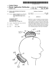
Application and removal of tc sensors ................................................................6-6
Application of SpO2 sensors ...............................................................................6-8
Patient monitoring (In vivo monitoring) ...........................................................6-11
Patient DMS ......................................................................................................6-13
Results in Normal view.....................................................................................6-16
Results in Trend table view...............................................................................6-18
Results in Trend curve view..............................................................................6-19
Analog output....................................................................................................6-21
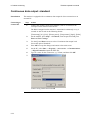
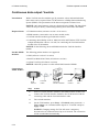
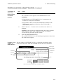
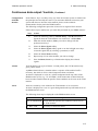
Continuous data output: standard......................................................................6-22
Continuous data output: VueLink .....................................................................6-24
Continuous data output: MonLink ....................................................................6-29
Data export: serial .............................................................................................6-30
Data export: USB ..............................................................................................6-33
Alarms...............................................................................................................6-34
How to print ......................................................................................................6-38
Blood gas comparison .......................................................................................6-44
In vivo calibration .............................................................................................6-45
7.
Troubleshooting ............................................................................................................. 7-1
The TCM4/40 systems ........................................................................................7-2
8.
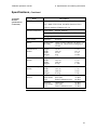
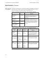
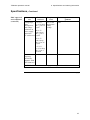
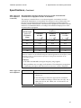
Specifications and ordering information...................................................................... 8-1
Specifications ......................................................................................................8-2
Accessories........................................................................................................8-14
TCM4/40 operator's manual
9.
Contents
Functional description ................................................................................................... 9-1
tcpCO2/tcpO2 measurement.......................................................................................... 9-2
Construction of sensors .......................................................................................9-3
pCO2 measuring principle ...................................................................................9-5
pO2 measuring principle......................................................................................9-6
Calibration of sensor ...........................................................................................9-7
Solutions and calibration gases .........................................................................9-10
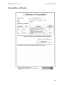
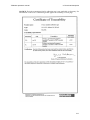
Traceability certificates.....................................................................................9-11
Pulse oximetry measurement ..................................................................................... 9-15
Measuring principle ..........................................................................................9-16
Calibration of sensor .........................................................................................9-17
Index
Date of issue
Contents
TCM4/40 operator's manual
1. Introduction
Names, intended use and limitations........................................................................ 1-2
Symbols used on the monitor................................................................................... 1-4
Symbols used in the manual..................................................................................... 1-6
1. Introduction
TCM4/40 operator's manual
Names, intended use and limitations
Proprietary
names
TCM4 monitor and TCM40 monitor.
Common names Transcutaneous pCO2/pO2 monitoring system (TCM4) and Transcutaneous
pCO2/pO2/SpO2/Pulse monitoring system (TCM40)
TCM4 series
monitors
The TCM4 and TCM40 monitoring systems are part of the TCM4 Series
monitoring system.
Reference
This operator’s manual for the TCM4/40 monitoring systems is intended for use as
a reference. It provides detailed operating instructions and answers to relevant
questions about your monitoring systems.
All rights
reserved
At the time of printing, the manual is in conformity with the systems. All rights are
reserved for instruments, circuits, techniques and names appearing in the manual.
Intended use
The TCM4 monitoring system is intended for continuous transcutaneous monitoring
of carbon dioxide (tcpCO2) and oxygen (tcpO2) partial pressures. It is indicated for
use on neonates, pediatrics, and adults not under gas anesthesia.
The TCM40 monitoring system is intended for continuous transcutaneous monitoring
of carbon dioxide (tcpCO2) and oxygen (tcpO2) partial pressures as well as of oxygen
saturation of arterial hemoglobin (SpO2) and pulse rate. It is indicated for use on
neonates, pediatrics and adults not under gas anesthesia.
Sensors
The sensors are provided non-sterile and are intended for reuse.
For information on site locations, see the relevant section about application of
sensors in chapter 6 In vivo monitoring.
Environment of In hospital/clinical environment.
use
Operator profile Only trained health care personnel are permitted to use the monitor.
Limitations
Transcutaneous monitoring is intended only as an adjunct in patient assessment
and must be used in conjunction with clinical signs and symptoms.
WARNING – Risk of incorrect measurements
tcpCO2/tcpO2 monitoring should not be used on patients in a compromised
hemodynamic state as this may cause incorrect measurements.
WARNING – Risk of incorrect measurements
The DS100A SpO2 sensor is contraindicated for use on active patients or
for prolonged use. It is not designed for long-term monitoring. Using this
sensor for long-term monitoring may result in incorrect measurements.
Continued on next page
1-2
TCM4/40 operator's manual
1. Introduction
Names, intended use and limitations, Continued
Limitations
(continued)
WARNING – Risk of allergic reactions
The OXIband A/N and P/I SpO2 sensors are contraindicated for use on
patients who exhibit allergic reactions to the pressure-sensitive adhesive
on the wraps.
CAUTION – US federal law restriction
Federal law restricts this device to sale by or on the order of a physician.
NOTICE: This equipment is not a blood gas device.
Legal notices
• Instruments should be repaired by authorized service personnel or by
Radiometer-certified representatives only.
• Purchase of the TCM40 monitoring system confers no express or implied license
under any Nellcor patent to use this instrument with any oximetry sensor that is
not manufactured or licensed by Nellcor.
1-3
1. Introduction
TCM4/40 operator's manual
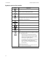
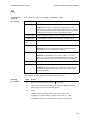
Symbols used on the monitor
Symbol
Explanation
CSA approved
Caution, consult accompanying documents
Temperature limitation
Indicates that the product complies with the requirements
of the Medical Device Directive 93/42/EEC June 1993.
This product is a class IIa device.
Serial number
Non-ionizing radiation
Type BF equipment (body floating)
Manufacturer
USB
Waste of Electrical and Electronic Equipment (WEEE)
The symbol indicates that:
• Radiometer Medical ApS and its distributors
within the European Union (EU) and associated
states have taken the necessary steps to comply
with the directive 2002/96/EC on waste electrical
and electronic equipment (WEEE)
• The instrument, when reaching its end of life, must
be collected and recycled separately from other
waste according to national requirements.
Please contact your local Radiometer distributor
for instructions.
Environmental implications:
WEEE contains materials that are potentially hazardous to
the environment and to human health.
Continued on next page
1-4
TCM4/40 operator's manual
1. Introduction
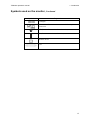
Symbols used on the monitor, Continued
Symbol
Explanation
COM gate
Ethernet interface connection to network. Not for phone
connection.
Off (Power: disconnection from the mains)
On (Power: connection to the mains)
Monitor on/off
Fuse
1-5
1. Introduction
TCM4/40 operator's manual
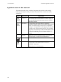
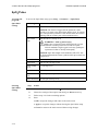
Symbols used in the manual
This manual contains alerts, which are important and should be read carefully
before performing the related procedures. The manual also contains non-safety
information.
Symbol
Signal word
Explanation
WARNING
A warning alerts the reader about a situation which, if
not avoided, could result in death or serious injury. It
may also describe potential serious adverse reactions
and safety hazards.
CAUTION
A caution alerts the reader about a potentially
hazardous situation which, if not avoided, may result in
minor or moderate injury to the user or the patient or
damage to the equipment or other property. It may also
be used to alert against unsafe practices. This includes
the special care necessary for the safe and effective use
of the device and the care necessary to avoid damage
to the device that may occur as a result of use or
misuse.
NOTICE
Addresses practical information that is not related to
personal injury ("need-to-know information").
Manufacturer
Indicates that the product complies with the
requirements of the Medical Device Directive
93/42/EEC June 1993.
This product is a class IIa device.
1-6
2. What is what
TCM4/40 monitoring systems.................................................................................. 2-2
Monitor – top and front ............................................................................................ 2-3
Monitor – rear .......................................................................................................... 2-4
The screen: general elements ................................................................................... 2-5
Online tutorials......................................................................................................... 2-8
Touch key glossary .................................................................................................. 2-9
2. What is what
TCM4/40 operator's manual
TCM4/40 monitoring systems
Introduction
The TCM4 monitoring system includes:
• Base unit
• tcpCO2/tcpO2 module
• Combined tcpCO2/tcpO2 sensors or single tcpCO2 sensor
The TCM40 monitoring system includes:
• Base unit
• tcpCO2/tcpO2 module and SpO2 module
• Sensors for tcpCO2/tcpO2 module: Combined tcpCO2/tcpO2 sensors or single
tcpCO2 sensor
• Sensors for SpO2 module: SpO2 sensors (Nellcor DS100A, Nellcor Oxiband A/N
or Nellcor Oxiband P/I)
NOTICE: For ordering information, see the section Accessories in chapter 8.
2-2
TCM4/40 operator's manual
2. What is what
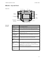
Monitor – top and front
Front view
Touch screen
Handle
Calibration
chamber
SpO2
module
tcpCO2/tcpO2
module
Battery
indicator
Monitor support
and holder for
sensor cable
ON/OFF button
Monitor-elevating support
Parts and
functions
Part
Function
Handle
For carrying the monitor.
Touch screen
For easy communication between operator and monitor.
Calibration
chamber
For storage and calibration of tcpCO2/tcpO2 sensor.
tcpCO2/tcpO2
module
For transcutaneous measurements of tcpCO2 and tcpO2 and
calibration of the sensor.
Monitor support
and holder for
sensor cable
For supporting the monitor and holding the sensor cable.
Monitor-elevating
support
For supporting the monitor at an elevated angle.
For turning the monitor ON and OFF.
ON/OFF button
Battery indicator
SpO2 module
For indicating whether the battery is being recharged or
not. If the light is on, the battery is being recharged.
NOTICE: Only possible if the power switch on the back
of the monitor is in the ON position.
For measurements of SpO2 and pulse rate.
(TCM40 monitor
only)
2-3
2. What is what
TCM4/40 operator's manual
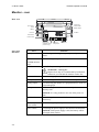
Monitor – rear
Rear view
tcpCO2/tcpO2
sensor socket
SpO2 sensor
socket
Module release
Battery
Ventilator
Line fuse
Power switch
Power socket
Ethernet (for
authorized service
personnel only)
Parts and
functions
Part
Battery
Serial port/
analog output
2 USB ports
Function
For allowing monitoring during transport and power
failure.
SpO2 sensor socket For connecting an SpO2 sensor to the monitor.
(TCM40 monitor
only)
Line fuse
1.25 AT. For preventing a short circuit.
WARNING – Risk of fire
Replace fuse only as recommended by Radiometer.
Otherwise you risk that the monitor catches fire.
Power socket
For connecting a power cord to the monitor.
Serial port (RS232) For connecting the monitor to an external computer.
Analog output
For connecting the monitor to a peripheral device such as a
polysomnograph.
USB ports
For connecting the monitor to an external printer and a
memory stick.
NOTICE: It is only possible to use one of the ports at a
time.
Module release
For releasing the sensor module from the monitor with a
release key.
tcpCO2/tcpO2
sensor socket
For connecting a tcpCO2/tcpO2 sensor to the monitor.
Power switch
For turning the power supply to the monitor ON and OFF.
NOTICE: If the power supply is ON, the battery will be
recharged when needed.
2-4
TCM4/40 operator's manual
2. What is what
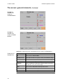
The screen: general elements
Screen types
There are two types of screens on the TCM4/40 monitors: view (i.e. Normal, Trend
table and Trend Curve) and menu screens.
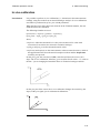
View screen
configuration
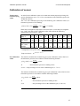
The view screens are divided into the following fields:
ID
Time/Date System/view status
Bat.
Curve display
pCO2/pO2 display
pCO2/pO2
---------------------------------------------
Pulse/SpO2 display
Power/SpO2
Touch keys
NOTICE: SpO2 and pulse rate are available on the TCM40 monitor only. On the
TCM4 monitor, the lower part of the curve display will either show the power
curve or be empty, and the Pulse/SpO2 display will always be empty (see examples
on next page).
Part
Shows
Time and date
The real time (24-hour cycle) and date
System/view
status
Normal view, Trend table view, Trend curve view, New
patient, Alert or Alarm
Bat.
The battery level when the monitor is running on battery.
ID
Full , almost full , low and critically low
Patient identification number. Gives access to Patient DMS.
Curve display
TCM4 monitor: pCO2, pO2 and power
TCM40 monitor: pCO2, pO2 and SpO2
Sensor status (e.g. Calibrating) and gas level (only displayed
during calibration and if there is 10 % or less gas left in the gas
cylinder).
Barometric pressure (only displayed during calibration).
pCO2/pO2
display
pCO2, pO2, Corr., Power, Temp, SmartHeat, In vivo calibration
Pulse/SpO2
display
Pulse, SpO2, "HI OFF" (SpO2 alarm high is disabled),
active,
(alarm is ON) and
(alarm is ON) and
(alarm is OFF)
(alarm is OFF)
Continued on next page
2-5
2. What is what
TCM4/40 operator's manual
The screen: general elements, Continued
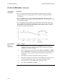
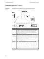
Example of
Normal view
screen on
TCM40 monitor
Example of
Normal view
screen on TCM4
monitor
NOTICE: In Measuring mode, the Event touch key replaces the Tutorial key.
Touch keys in
Normal view
Touch key
Function
ID
Gives access to Patient DMS.
Site time xx:xx
Resets the site timer to its preset value (see Parameter setup).
Tutorial
Gives access to instruction videos – when not monitoring.
Event
Marks an event during monitoring.
Calibrate
Starts a calibration of the sensor (and the SmartCal period, if
the function is set to ON in the setup).
Print
Gives access to the Printer start/stop time screen.
Setup
Gives access to all the setup menus and submenus.
Alarm silence
Silences/resets the alarm system.
Continued on next page
2-6
TCM4/40 operator's manual
2. What is what
The screen: general elements, Continued
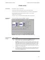
Menu screen
configuration
The menu screens are divided into the following fields:
Menu tabs
Submenus/settings
Touch keys
The menu screens contain the following tabs, which give access to the setup menus
and submenus: View, Parameter, Calibration, Printer and Technical (password
protected).
Example of
menu screen
Menu tabs
Settings
Submenus
Touch keys
NOTICE: SpO2 is available on the TCM40 monitor only.
Menu screen
touch keys
Touch key
Function
OK
Accepts the changes and returns to the main screen.
Apply
Accepts the changes without leaving the menu screen.
Cancel
Returns to the main screen without saving changes.
2-7
2. What is what
TCM4/40 operator's manual
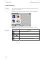
Online tutorials
Tutorials
The tutorials are short video sequences of commonly used procedures. To access
the tutorials, press Tutorial.
NOTICE: In Measuring mode, the Event touch key replaces the Tutorial key.
NOTICE: The DS100A sensor tutorial can only be selected on the TCM40
monitor.
Touch keys
Touch key
Function
Pauses the selected tutorial.
Plays the selected tutorial.
and
Scroll backward/forward one step in the selected tutorial.
Returns to the TCM tutorials screen.
Exits the tutorial and returns to Normal view.
2-8
TCM4/40 operator's manual
2. What is what
Touch key glossary
Touch keys
In the text, touch keys are written in bold italic throughout the manual.
The glossary of all the touch keys used in the software with their description is
given in alphabetical order in the table below:
Touch key
Function
Adds a check mark to the highlighted patient ID/session
number (in Patient DMS).
Displays detailed information about the highlighted patient
ID/session number (in Patient DMS).
Alarm silence
Silences/resets the alarm system.
Apply
Accepts the changes made in the settings without leaving
the respective menu screen.
Blood gas
Gives access to the Blood gas setup where blood gas
values can be keyed in.
Cal. status
Gives information about the last calibration.
Calibrate
Starts a calibration of the electrode.
Cancel
Returns to the main screen without saving the changes
made in the settings.
Cursor
Adds/removes a cursor in the Trend curve view.
Date/time
Gives access to the Date/time setup (password protected).
Default values
Changes all settings to Radiometer default values
(password protected).
Delete config. file
Part of the Service setup (only for service purposes).
Enter
Registers the entered password.
Event
Marks an event during monitoring.
Export
Exports the patient information and measuring data for the
patient IDs/session numbers with a check mark (in Patient
DMS).
ID
Gives access to Patient DMS.
In vivo calibration Starts an in vivo calibration, i.e. a correction of the
measured tcpCO2/tcpO2 values with the keyed-in blood gas
values.
Normal
Gives access to the Normal view setup.
Continued on next page
2-9
2. What is what
TCM4/40 operator's manual
Touch key glossary, Continued
Touch keys
(continued)
Touch key
Function
OK
Accepts the changes made in the settings and returns to the
main screen.
pCO2
In the Parameter menu, it gives access to the pCO2
parameter setup.
In the Trend curve setup, it gives access to the pCO2 curve
range screen.
pO2
In the Parameter menu, it gives access to the pO2
parameter setup.
In the Trend curve setup, it gives access to the pO2 curve
range screen.
Power
Gives access to the Power range screen.
Print
Gives access to the Printer start/stop time screen.
Service menu
Gives access to the Service setup (password protected).
Setup
Gives access to all the Setup menus.
Site time
Resets the site timer to its preset value (see Parameter
setup).
SmartCal
Keeps the electrode ready for use (i.e. calibrated for max.
12 hours).
SpO2/Pulse
In the Parameter menu, it gives access to the SpO2/Pulse
parameter setup.
In the Trend curve setup, it gives access to the SpO2/Pulse
curve range screen.
System info
Part of the Service setup (only for service purposes).
Tech. settings
Gives access to the Technical settings (password
protected).
Test
Part of the Service setup (only for service purposes).
Touch screen
calibration
Part of the Service setup (only for service purposes).
Trend curve
Gives access to the Trend curve setup.
Trend table
Gives access to the Trend table setup.
Tutorial
Gives access to instruction videos.
Continued on next page
2-10
TCM4/40 operator's manual
2. What is what
Touch key glossary, Continued
Arrow touch
keys
Touch key
or
Function
Changes the settings of the highlighted option.
or
Scrolls the displayed screen/parameters upward or
downward.
or
Scrolls the displayed screen/parameters forward or
backward.
Scrolls quickly to the most recent result.
Deletes one character at a time.
or
Tutorial touch
keys
Touch key
Moves one character at a time to the left or the right.
Function
Pauses the selected tutorial.
Plays the selected tutorial.
and
Scroll backward/forward one step in the selected tutorial.
Returns to the TCM Tutorials screen.
Exits the tutorial and returns to Normal view.
2-11
2. What is what
2-12
TCM4/40 operator's manual
3. Menu structure and setup programs
Menu structure ...................................................................................................... 3-2
List of setup programs........................................................................................... 3-3
View setup............................................................................................................ 3-4
Normal view.......................................................................................................... 3-5
Trend table view.................................................................................................... 3-7
Trend curve view .................................................................................................. 3-8
Parameter setup .................................................................................................. 3-9
pCO2 .................................................................................................................... 3-10
pO2 ...................................................................................................................... 3-11
SpO2/Pulse .......................................................................................................... 3-12
Blood gas............................................................................................................. 3-13
Calibration setup............................................................................................... 3-14
SmartCal.............................................................................................................. 3-15
Calibration status................................................................................................. 3-16
Printer setup ...................................................................................................... 3-17
Technical setup .................................................................................................. 3-19
Technical settings................................................................................................ 3-20
Date/time............................................................................................................. 3-22
Default values ..................................................................................................... 3-23
3. Menu structure and setup programs
TCM4/40 operator's manual
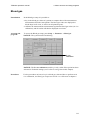
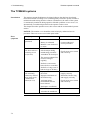
Menu structure
Menu structure
The following diagram illustrates the menu structure of the TCM4/40 monitors.
Setup
View
Parameter
Calibration
SmartCal T
Cal. status
pCO2
pO2
O2/Pulse*
Blood gas
Sp
Main screen
Normal
Trend table
View Ti
Time span
Curve ranges
Pow
me
interval
Screen saver
se
Date
Technical
ime
interval
Time span
Report type
Curve ranges
Printer type
Enter
password
Trend curve
pCO2
pO2
er**
Technical
settings
Printer
Time span
Curve
ranges
pCO2
pO2
Power
SpO2/Pulse*
Select curves
Date/time
Date/time
ttings
format
Service
menu
Default
values
For service
personnel
only
* Available on the TCM40 monitor only.
** Available on the TCM4 monitor only.
NOTICE: If no touch key is activated for 30 seconds, the main screen (Normal
view) is displayed.
3-2
TCM4/40 operator's manual
3. Menu structure and setup programs
List of setup programs
Accessing the
Setup menus
Press the Setup touch key to get access to the Setup menus:
• View
• Parameter
• Calibration
• Printer
• Technical
Detailed information about the five main Setup menus is given in the following
sections.
3-3
3. Menu structure and setup programs
TCM4/40 operator's manual
View setup
3-4
Normal view.....................................................................................................
3-5
Trend table view...............................................................................................
3-7
Trend curve view .............................................................................................
3-8
TCM4/40 operator's manual
3. Menu structure and setup programs
Normal view
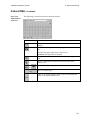
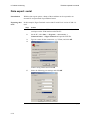
Introduction
In the Normal view setup, it is possible to select which parameters will be shown
in Normal view, to set the time span of the graphical display and to activate the
screen saver.
NOTICE: If no touch key is activated for 30 seconds, the main screen (Normal
view) is displayed.
Accessing the
program
To access the Normal view setup, press Setup → Normal.
Normal view setup on TCM40 monitor:
Normal view setup on TCM4 monitor:
Selecting
Normal view
options
Step
1.
Action
Use the Up and Down arrows to select the curves that are to be shown
in the curve area in Normal view.
NOTICES:
• Parameter values will always be shown.
• The number of parameters to choose from depends on the sensor
type installed (combined pCO2/pO2 or pCO2 only), and whether the
pO2 parameter is set to ON or OFF in Technical setup.
Continued on next page
3-5
3. Menu structure and setup programs
TCM4/40 operator's manual
Normal view, Continued
Selecting
Normal view
options
(continued)
Step
2.
Action
Use the Up and Down arrows to select the time span.
NOTICE: The time span selection only applies to the pCO2, pO2 and
Power curves.
3.
Select the curve range options of the individual parameters by pressing
each of the parameters and, in the appearing screens, selecting the high
and low values.
4.
Press OK to accept the changes and return to the Normal view setup
screen, or press Cancel to return to the Normal view setup screen
without saving changes.
5.
If required, select (3) the screen saver.
NOTICES:
• To activate the screen saver, it is necessary to press OK before
leaving the Normal view setup.
• The option is only visible if it has been activated in Technical
settings.
• The screen saver is primarily meant for sleep labs, to reduce the
backlight from the display.
• Touching the screen deactivates the screen saver; and to reactivate it,
the option must be selected in Normal view setup.
6.
Press:
• OK to accept the changes and return to the main screen
• Apply to accept the changes without leaving the Normal view setup
• Cancel to return to the main screen without saving changes
3-6
TCM4/40 operator's manual
3. Menu structure and setup programs
Trend table view
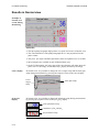
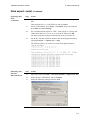
Introduction
In the Trend table setup, it is possible to select the time interval between each
record in the Trend table.
Accessing the
program
To access the Trend table setup, press Setup → Trend table.
Selecting
Trend table
options
Step
Action
1.
Use the Up and Down arrows to select the time interval.
2.
Press:
• OK to accept the changes and return to the main screen
• Apply to accept the changes without leaving the Trend table setup
• Cancel to return to the main screen without saving changes
3-7
3. Menu structure and setup programs
TCM4/40 operator's manual
Trend curve view
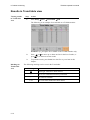
Introduction
In the Trend curve setup, it is possible to set the time span of the graphic display
and the ranges for pCO2, pO2, Power and SpO2/Pulse, and to select which
parameter(s) (maximum two) should be displayed on the Trend curve.
NOTICE: SpO2 and pulse are available on the TCM40 monitor only.
Accessing the
program
Selecting
Trend curve
options
To access the Trend curve setup, press Setup → Trend curve.
Step
Action
1.
Use the Up and Down arrows to select the time span.
2.
Select maximum two parameters to be displayed as trend curves.
NOTICE: If two parameters are selected, one of these must be
deselected in order to be able to select a new parameter.
3.
Select the curve range options of the individual parameters by
pressing each of the parameters and, in the appearing screens,
selecting the high and low values, using the arrow keys.
4.
Press OK to accept the changes and return to the Trend curve setup
screen, or press Cancel to return to the Trend curve setup screen
without saving changes.
5.
In the Trend curve setup screen, press:
• OK to accept the changes and return to the main screen
• Apply to accept the changes without leaving the Trend curve setup
• Cancel to return to the main screen without saving changes
3-8
TCM4/40 operator's manual
3. Menu structure and setup programs
Parameter setup
WARNING – Risk of incorrect monitoring
Make sure to select the alarm limits carefully. Setting alarm limits to
extreme values can render the alarm system useless.
pCO2 ................................................................................................................. 3-10
pO2 ................................................................................................................... 3-11
SpO2/Pulse ....................................................................................................... 3-12
Blood gas.......................................................................................................... 3-13
3-9
3. Menu structure and setup programs
TCM4/40 operator's manual
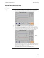
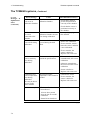
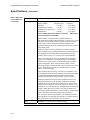
pCO2
Accessing the
program
To access the pCO2 setup, press Setup → Parameter → pCO2.
pCO2 settings
Settings
Options
pCO2 alarm
ON/OFF
NOTICE: The alarm is triggered if the parameter value
exceeds or is equal to the alarm limit (high or low). It consists
of a visual part (the parameter value and an alarm text will be
flashing) and an acoustic part (a discontinuous tone).
pCO2 alarm high 6-200 mmHg (in steps of 1); 0.8-26.7 kPa (in steps of 0.1)
pCO2 alarm low
5-99 mmHg (in steps of 1); 0.7-9.9 kPa (in steps of 0.1)
Alarm sound
level1
1-5 (1 is minimum)
Sensor temp. 2
37.0-45.0 °C (in steps of 0.5)
NOTICE: If the set sensor temperature is changed during
measurement, a new calibration is required.
SmartHeat2
ON/OFF
NOTICE: If SmartHeat is set to ON, it adds +1 °C (max.
temp. 45 °C) to the set sensor temperature for 5 minutes after
the sensor has been removed from the calibration chamber.
Site time2
OFF; ½-12 hours (in steps of ½ hour)
Site time heat
2
ON/OFF
NOTICE: If Site time heat is set to OFF, the sensor heat is
switched off when the site timer reaches zero; if set to ON,
the heat continues.
1
2
Selecting
pCO2 settings
The setting of this option is common to pCO2, pO2 and SpO2.
The setting of this option is common to pCO2 and pO2.
Step
Action
1.
Select the relevant option with the
2.
Choose the settings of that option with the Up or Down arrow key.
3.
Follow steps 1-2 for the remaining options.
4.
Press:
touch key.
• OK to accept the changes and return to the main screen
• Apply to accept the changes without leaving the pCO2 setup
• Cancel to return to the main screen without saving changes
3-10
TCM4/40 operator's manual
3. Menu structure and setup programs
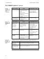
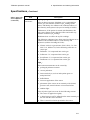
pO2
Accessing the
program
To access the pO2 setup, press Setup → Parameter → pO2.
pO2 settings
Settings
Options
pO2 alarm
ON/OFF
NOTICE: The alarm is triggered if the parameter value
exceeds or is equal to the alarm limit (high or low). It consists
of a visual part (the parameter value and an alarm text will be
flashing) and an acoustic part (a discontinuous tone).
pO2 alarm high
1-800 mmHg (in steps of 1); 0.1-99.9 kPa (in steps of 0.1)
pO2 alarm low
0-99 mmHg (in steps of 1); 0.0-9.9 kPa (in steps of 0.1)
Alarm sound
level1
1-5 (1 is minimum)
Sensor temp.2
37.0-45.0 °C (in steps of 0.5)
NOTICE: If the set sensor temperature is changed during
measurement, a new calibration is required.
SmartHeat2
ON/OFF
NOTICE: If SmartHeat is set to ON, it adds +1 °C (max.
temp. 45 °C) to the set sensor temperature for 5 minutes after
the sensor has been removed from the calibration chamber.
Site time2
OFF; ½-12 hours (in steps of ½ hour)
Site time heat
2
ON/OFF
NOTICE: If Site time heat is set to OFF, the sensor heat is
switched off when the site timer reaches zero; if set to ON,
the heat continues.
1
2
Selecting
pO2 settings
The setting of this option is common to pCO2, pO2 and SpO2.
The settings of these options are common to pCO2 and pO2.
Step
Action
1.
Select the relevant option with the
2.
Choose the settings of that option with the Up or Down arrow key.
3.
Follow steps 1-2 for the remaining options.
4.
Press:
touch key.
• OK to accept the changes and return to the main screen
• Apply to accept the changes without leaving the pO2 setup
• Cancel to return to the main screen without saving changes
3-11
3. Menu structure and setup programs
TCM4/40 operator's manual
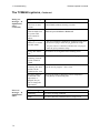
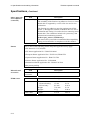
SpO2/Pulse
Accessing the
program
SpO2/Pulse
settings
To access the SpO2/Pulse setup, press Setup → Parameter → SpO2/Pulse.
Settings
SpO2 alarm
Options
ON/OFF
NOTICE: The alarm is triggered if the parameter value
exceeds or is equal to the alarm limit (high or low). It consists
of a visual part (the parameter value and an alarm text will be
flashing) and an acoustic part (a discontinuous tone).
SpO2 alarm
high
OFF/86-100 % (in steps of 1)
WARNING – Risk of patient injury
Make sure to select the upper alarm limit for oxygen
saturation carefully and in accord with accepted
clinical standards. High oxygen levels may predispose
a premature infant to develop retinopathy.
NOTICE: SpO2 alarm high can be disabled ("HI OFF" will
be displayed beneath the alarm symbol) while SpO2 alarm low
is kept active.
SpO2 alarm low 85-99 % (in steps of 1)
SatSeconds
OFF/10-100 (in steps of 10)
Alarm sound
level1
1-5 (in steps of 1)
Pulse alarm
ON/OFF
Pulse alarm
high
35-240 bpm (in steps of 5)
Pulse alarm low 30-235 bpm (in steps of 5)
1
Selecting
SpO2/Pulse
settings
The setting of this option is common to pCO2, pO2 and SpO2.
Step
Action
1.
Select the relevant option with the
2.
Choose the settings of that option with the Up or Down arrow key.
3.
Follow steps 1-2 for the remaining options.
4.
Press:
touch key.
• OK to accept the changes and return to the main screen
• Apply to accept the changes without leaving the SpO2/Pulse setup
• Cancel to return to the main screen without saving changes
3-12
TCM4/40 operator's manual
3. Menu structure and setup programs
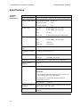
Blood gas
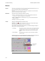
Introduction
In the Blood gas setup it is possible to:
• key in the blood gas values of a patient to compare these with transcutaneous
measurements from the same patient. The blood gas values are displayed as
blood drops in all views, as well as on all printed reports.
• calibrate the transcutaneous measurements against the blood gas values (in vivo
calibration), and all results will then be displayed as red stars.
Accessing the
program
To access the Blood gas setup, press Setup → Parameter → Blood gas.
NOTICE: The system must be monitoring.
In vivo
calibration
NOTICE: The In vivo calibration touch key is only visible if the option has been
activated in Technical settings (see Technical settings later in this chapter).
Procedures
For the procedures on how to key in a blood gas value and how to perform an in
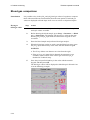
vivo calibration, see Blood gas comparison and In vivo calibration in chapter 6.
3-13
3. Menu structure and setup programs
TCM4/40 operator's manual
Calibration setup
SmartCal........................................................................................................... 3-15
Calibration status.............................................................................................. 3-16
3-14
TCM4/40 operator's manual
3. Menu structure and setup programs
SmartCal
Purpose
The SmartCal function makes sure that the monitor is always ready for monitoring
by calibrating the sensor when needed.
Accessing the
program
To access the SmartCal setup, press Setup → Calibration → SmartCal.
SmartCal
settings
Settings
Options
SmartCal
ON/OFF
Function
Enables/disables the SmartCal function.
NOTICES:
• When enabled, the monitor will calibrate automatically. The calibration interval may vary
from 5 minutes to 2 hours; and the maximum
measuring time will be reduced accordingly.
• Although the option is enabled, it is necessary
to press Calibrate to start a SmartCal period.
SmartCal
duration
Elapsed
time
Selecting
SmartCal
settings
Step
Forever/
1-12 hours
(in steps of 1)
0:00-12:00
(hours:minutes)
Defines the duration of the SmartCal period.
NOTICE: If set to forever, the monitor will
calibrate whenever the sensor is placed in the
calibration chamber; if set to 1-12 hours, the
monitor will calibrate within the selected period,
and after a SmartCal period, it will be necessary
to press Calibrate to start a new SmartCal period.
Shows how much time has elapsed of the active
SmartCal period.
Action
1.
Select the relevant option with the
2.
Choose the settings of that option with the Up or Down arrow key.
3.
Follow steps 1-2 for the remaining options.
4.
Press:
• OK to accept the changes and return to the main screen
• Apply to accept the changes without leaving the SmartCal setup
• Cancel to return to the main screen without saving changes
touch key.
3-15
3. Menu structure and setup programs
TCM4/40 operator's manual
Calibration status
Introduction
The Calibration status screen shows the status of the last calibration.
Accessing the
program
To access the Calibration status screen, press Setup → Calibration → Cal. Status.
Calibration
status
information
Status info
Last cal.
Unit
Description
hour:minutes Shows the time of the last calibration.
Set temp.
°C
Shows the sensor temperature during the last
calibration.
Barometer
mmHg/kPa
Shows the barometric pressure during the last
calibration.
Cal. value O2
mmHg/kPa
Shows the O2 calibration value.
Cal. value CO2
mmHg/kPa
Shows the CO2 calibration value.
Gas level
%
Shows how much calibration gas is left in the
cylinder.
NOTICE: The level will be displayed as "High"
until there is less than 10 % left in the gas
cylinder, and then as a percentage.
Press OK or Cancel to return to the main screen.
3-16
TCM4/40 operator's manual
3. Menu structure and setup programs
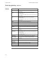
Printer setup
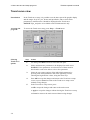
Introduction
In the Printer setup, it is possible to:
• set the time interval between two values on the table printout
• set the time span of the measurements that are to be shown on the printout
• choose whether to print out the report as a table, a curve or both
• adjust the set curve ranges
• connect a color or a black-and-white (B/W) printer to the monitor
Accessing the
program
To access the Printer setup, press Setup → Printer.
NOTICE: SpO2 and pulse are available on the TCM40 monitor only.
Selecting printer
settings
Step
Action
1.
Select the time interval with the Up and Down arrow keys.
2.
Select the time span with the Up and Down arrow keys.
NOTICE: The selected time span will influence the start time of the
Printer start/stop time screen, as the interval between the printer start
time and the printer stop time corresponds to the time span; i.e. if the
time span is set to 1 hour, the interval between the printer start time
and the printer stop time will also be 1 hour (see also How to print in
chapter 6: In vivo monitoring).
3.
To change the curve range for pCO2, pO2, Power or SpO2/Pulse, press
the relevant parameter touch key and select the high and low values,
using the Up and Down arrows.
Continued on next page
3-17
3. Menu structure and setup programs
TCM4/40 operator's manual
Printer setup, Continued
Selecting printer
settings
(continued)
Step
Action
4.
Press OK to accept the changes and return to the Printer setup, or press
Cancel to return to the Printer setup without saving the changes.
5.
Select at least one report type: Table and/or Curve.
6.
Select printer type: color or B/W (i.e. black and white).
NOTICES:
• It is only possible to connect a local printer to the monitor. Printing
over the network is not supported.
• Radiometer recommends that you use an HP printer with PCL3
protocol.
7.
Press:
• OK to accept the changes and return to the main screen
• Apply to accept the changes without leaving the Printer setup
• Cancel to return to the main screen without saving changes
3-18
TCM4/40 operator's manual
3. Menu structure and setup programs
Technical setup
Technical settings............................................................................................. 3-20
Date/time.......................................................................................................... 3-22
Default values .................................................................................................. 3-23
3-19
3. Menu structure and setup programs
TCM4/40 operator's manual
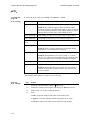
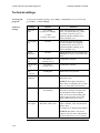
Technical settings
Accessing the
program
Technical
settings
To access the Technical settings, press Setup → Technical (enter password and
press Enter) → Tech. Settings.
Settings
Meta. corr.
factor
Options
0-15 mmHg
(in steps of 1 mmHg);
0-1 kPa
(in steps of 0.1 kPa)
Function
Defines the metabolic correction
factor. To indicate that CO2 values
have been corrected, "Corr." is
displayed together with the pCO2
value in Normal view.
Severinghaus
corr.
ON/OFF
If set to ON, all CO2 values are
corrected with the Severinghaus
correction factor, and "Corr." is
displayed together with the pCO2
value in Normal view.
In vivo
calibration
ON/OFF
Enables/disables access to the In vivo
calibration touch key in the Blood gas
setup.
Cal. gas mix
pO2
0.0-100.0 %
(in steps of 0.1)
A calibration constant.
Cal. gas mix
pCO2
0.0-10.0 %
(in steps of 0.1)
A calibration constant.
Unit
pCO2/pO2
mmHg/kPa
pO2
parameter
ON/OFF
Defines the pCO2/pO2 unit.
Defines whether to display the pO2
parameter or not.
NOTICE: This option only has an
effect when a combined tcpCO2/tcpO2
sensor is connected to the monitor.
Alarm mode
Latching/
non-latching
Defines whether the alarm is latching
(the monitor remains in alarm status
even though the alarm condition
ceases to exist) or non-latching (the
monitor resets itself as soon as the
alarm condition ceases to exist).
Continuous
data output
OFF, Standard, VueLink,
MonLink or Raw data
Gives four possibilities for data
output: standard, VueLink, MonLink
and raw data.
See chapter 6 for detailed information.
NOTICE: Raw data is for service
purposes only. For more information,
see the TCM4 Series service manual.
Continued on next page
3-20
TCM4/40 operator's manual
3. Menu structure and setup programs
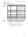
Technical settings, Continued
Technical
settings
(continued)
Option
Range (default)
Function
Data export
OFF, USB or Serial
Enables access to the Export touch
key (in Patient DMS), which is used to
export a dump of the trend data to a
memory stick or an external PC.
NOTICE: "Serial" is only available if
"Continuous data output" is set to
OFF.
Data export
interval
2, 10, 30 or 60 seconds
Display
brightness
10-100 %
(in steps of 10)
Defines the interval between the
export of data.
Defines the backlight brightness of the
display.
NOTICE: Full backlight reduces the
lifetime of the display.
Screen saver
Selecting
technical
settings
ON/OFF
Makes a screen saver option available
in Normal view setup.
pO2 analog
range
0-200 or 0-800 mmHg;
0.0-26.7 or 0.0-99.9 kPa
Defines the pO2 analog output range.
pCO2 analog
range
0-100 or 0-200 mmHg;
0.0-13.3 or 0.0-26.7 kPa
Defines the pCO2 analog output range.
Step
Action
1.
Select the relevant option with the
2.
Choose the settings of that option with the Up or Down arrow key.
3.
Follow steps 1-2 for the remaining options.
4.
Press:
• OK to accept the changes and return to the main screen
touch key.
• Apply to accept the changes without leaving the Technical settings
• Cancel to return to the main screen without saving changes
3-21
3. Menu structure and setup programs
TCM4/40 operator's manual
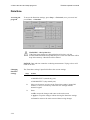
Date/time
Accessing the
program
To access the Date/time settings, press Setup → Technical (enter password and
press Enter) → Date/time.
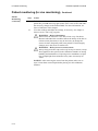
WARNING – Risk of data loss
If the Date/time settings are changed backward in time, only the
measurements that have been performed prior to the new date/time will be
kept in the memory. Other data will be deleted.
.
NOTICE: Date and time cannot be set during measurement. Trying to do so will
result in an alert.
Changing
date/time
settings
The "Date/time settings" input field reflects the current settings.
Step
1.
Action
Select date format:
• MM-DD-YYYY (month-day-year)
• DD-MM-YYYY (day-month-year)
2.
Move one character at a time in the "Date/time settings" input field
with the << and >> touch keys. Enter the new settings with the
numeric keypad.
3.
Press:
• OK to accept the changes and return to the main screen
• Apply to accept the changes without leaving the Date/time settings
• Cancel to return to the main screen without saving changes
3-22
TCM4/40 operator's manual
3. Menu structure and setup programs
Default values
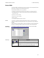
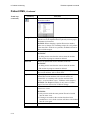
Introduction
The Default values function changes all parameter and monitor settings to factory
defaults. The default values are listed below.
NOTICE: When changing all settings to factory defaults, all kPa settings will
change to mmHg.
Changing
settings to
factory defaults
Step
Action
1.
Press Setup → Technical (enter password and press Enter) →
Default values.
2.
A dialog box with the text "This will return the monitor into default
setup and current setup will be lost" appears.
Press OK to change all parameter and monitor settings to factory
defaults or Cancel to exit without changing settings.
List of default
settings
Menus
Normal view
Settings
Curve selection
Default
TCM40 monitor: pCO2/pO2/SpO2
pCO2/pO2/Power
TCM4 monitor:
Time span
1 hour
Table view
Time interval
15 minutes
Curve view
Time span
8 hours
Curve selection
TCM40 monitor: pCO2 and SpO2
pCO2 and pO2
TCM4 monitor:
Curve range
pCO2 high
60 mmHg/8.0 kPa
pCO2 low
0 mmHg/0.0 kPa
pO2 high
200 mmHg/26.7 kPa
pO2 low
0 mmHg/0.0 kPa
Power high
400 mW
Power low
0 mW
SpO2 high
100 %
SpO2 low
90 %
Pulse high
200 bpm
Pulse low
0 bpm
Continued on next page
3-23
3. Menu structure and setup programs
TCM4/40 operator's manual
Default values, Continued
List of default
settings
(continued)
Menus
pCO2
pO2
SpO2/Pulse
Calibration
Settings
Default
pCO2 alarm
ON
pCO2 alarm high
50 mmHg/6.7 kPa
pCO2 alarm low
30 mmHg/4.0 kPa
Alarm sound level
2
Sensor temp.
43.0 °C
SmartHeat
OFF
Site time
4 hours
Site time heat
OFF
pO2 alarm
ON
pO2 alarm high
95 mmHg/12.7 kPa
pO2 alarm low
60 mmHg/8.0 kPa
Alarm sound level
2
Sensor temp.
43.0 °C
SmartHeat
OFF
Site time
4 hours
Site time heat
OFF
SpO2 alarm
ON
SpO2 alarm high
OFF
SpO2 alarm low
85 %
SatSeconds
OFF
Alarm sound level
2
Pulse alarm
ON
Pulse alarm high
170 bpm
Pulse alarm low
40 bpm
SmartCal
OFF
SmartCal duration
4 hours
Continued on next page
3-24
TCM4/40 operator's manual
3. Menu structure and setup programs
Default values, Continued
List of default
settings
(continued)
Menus
Printer
Technical
Settings
Default
Time interval
15 minutes
Time span
1 hour
Report type
Table and curve
Printer type
Color
Meta. corr. factor
7 mmHg/1.0 kPa
Severinghaus corr.
ON
In vivo calibration
OFF
Cal. gas mix pO2
20.9 %
Cal. gas mix pCO2
7.5 %
Unit pCO2/ pO2
mmHg
pO2 parameter
ON
Alarm mode
Non-latching
Continuous data
output
OFF
Data export
OFF
Data export interval 10 seconds
Date/time
Display brightness
70 %
Screen saver
OFF
pCO2 analog range
0-200 mmHg/0.0-26.7 kPa
pO2 analog range
0-800 mmHg/0.0-99.9 kPa
Date format
DD-MM-YYYY
3-25
3. Menu structure and setup programs
3-26
TCM4/40 operator's manual
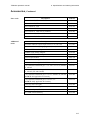
4. Installation and maintenance
Operating requirements.............................................................................................4-2
Installing the monitoring system...............................................................................4-3
Shutting down the monitor........................................................................................4-5
Cleaning the monitor.................................................................................................4-6
Maintenance of the monitor ......................................................................................4-7
Preparation and maintenance of the tc sensors....................................................4-9
General information about remembraning ..............................................................4-10
Cleaning the sensor head of the E5480 sensor........................................................4-11
Membraning the E5480 sensor................................................................................4-12
Membraning the E5280 and E5260 sensors............................................................4-13
Cleaning, disinfection and storage of sensors .........................................................4-15
Maintenance of the SpO2 sensors.........................................................................4-16
4. Installation and maintenance
TCM4/40 operator's manual
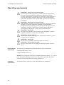
Operating requirements
WARNING – Risk of incorrect measurements
Do not use the monitor adjacent to or stacked with other equipment as
these can cause electromagnetic interference and thereby result in
incorrect measurements. If stacking or use adjacent to other equipment is
necessary, the monitor should be observed to verify normal operation
before used on patients. See the section EMC approvals and compliance
in chapter 8.
WARNING – Risk of incorrect measurements
When installing, operating or servicing the monitor, special consideration
should be given to the information regarding the electromagnetic
precautions for this equipment given in the section EMC approvals and
compliance in chapter 8. Otherwise the monitor may be affected by
electromagnetic interference, causing incorrect measurements.
WARNING – Risk of fire
Do not place the monitor in an enriched oxygen atmosphere or inside a
hyperbaric chamber as it may cause a fire hazard.
WARNING – Risk of explosion
Do not use the monitor in the presence of flammable anesthetics or gases
as it may cause an explosion.
WARNING – Risk of fire
Do not cover the ventilator as this may cause it to seize up.
WARNING – Risk of electrical shock
Do not use the monitor if it is damaged as this may result in electrical
shock.
Environmental
requirements
The following environmental requirements must be observed at all times:
• ambient temperature: 5-40 °C
• relative humidity: 20-80 %.
NOTICE: Do not operate the monitor at ambient temperatures below 5 °C or above
40 °C and relative humidity below 20 % or above 80 %. Operating the monitor
outside these limits may affect the readings of the device.
Ventilation
requirements
4-2
The monitor must be located in a well-ventilated dust-free atmosphere.
TCM4/40 operator's manual
4. Installation and maintenance
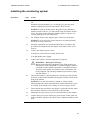
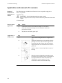
Installing the monitoring system
Procedure
Step
1.
Action
NOTICE: While installing the modules, the monitor must be turned
off.
Install the relevant module(s) (i.e. tc and SpO2) by pressing each
module completely into the base unit until a click is heard.
NOTICE: If using an E5480 sensor, the gasket in the calibration
chamber must be code no. 837-488; and if using an E5280 or E5260
sensor, the gasket in the calibration chamber must be code no. 837159 (see package insert for instructions).
2.
For TCM40 monitor only: Plug the SpO2 sensor into the monitor.
NOTICE: It is not necessary for the monitor to be turned off while
the sensor is being connected.
3.
Install the calibration gas cylinder and the battery according to the
procedures described later in this chapter under Maintenance of the
monitor.
4.
Connect the monitor power cord to
• the power socket at the rear of the monitor and
• an appropriate power supply
5.
Connect the system to external equipment, if required.
WARNING – Risk of personal injury
Before connecting other equipment to the TCM monitor, the
manufacturer of the equipment or a qualified engineer must be
consulted to ensure that the equipment is compatible and that
the safety of the patient, the operator or the environment will
not be impaired. The resulting combined system must comply
with EN 60601-1-1.
6.
Turn on the monitor by pressing the power switch to the ON position
at the rear of the monitor and then pressing the ON/OFF button on the
front of the monitor.
NOTICE: Every time the monitor is turned on, a beep sounds,
indicating that it has been checked that the sound of the alarm system
is working. If the sound is not working, an error message is shown.
7.
Check that the date and time in the display correspond with the actual
date and time. Otherwise correct them in Technical setup.
8.
Membrane the tcpCO2/tcpO2 sensor as described later in this chapter.
9.
Connect the tcpCO2/tcpO2 sensor plug to the sensor socket at the rear
of the tc module, and place the sensor in the calibration chamber at the
front.
Continued on next page
4-3
4. Installation and maintenance
TCM4/40 operator's manual
Installing the monitoring system, Continued
Procedure
(continued)
Step
Action
10.
Check that the tc module is functioning: The message "Calibration
required" is displayed on the screen. Leave it until step 12.
11.
Change View or Setup settings, if required, by pressing Setup. See
chapter 3: Menu structure and setup programs.
NOTICE: The monitor is delivered with default settings (see these in
the section Default values in chapter 3).
12.
4-4
Calibrate the sensor as described in chapter 5: Calibration.
TCM4/40 operator's manual
4. Installation and maintenance
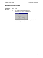
Shutting down the monitor
Shutting down
the monitor
Step
1.
Action
Press the
button on the front of the monitor.
The following system message will be displayed:
2.
Press OK to shut down the monitor – the message "Saving data. Please
wait." will be displayed – or Cancel to return to the main screen
without shutting down the monitor.
4-5
4. Installation and maintenance
TCM4/40 operator's manual
Cleaning the monitor
Cleaning the
exterior
When cleaning the monitor:
• Shut down the monitor by following the procedure described earlier in this chapter
• Use a cloth that is lightly dampened with soapy water
• Do not use abrasive cleansers or pads: the finish may become damaged
• Do not use aggressive detergents. Extensive use may cause the plastic to become
brittle and cracks may occur.
Cleaning the
touch screen
A dry or lightly dampened soft, lint-free cloth may be used to clean the monitor's
touch screen. Simply wipe the screen gently to remove fingerprints and/or dirt. To
avoid streaking, an approved screen cleaner is recommended.
Disinfection of
outer surfaces
Disinfection of the monitor exterior and touch screen is performed when appropriate.
The disinfection frequency depends on local requirements and the use of the monitor.
NOTICE: Follow legal requirements and local rules for safe work practices with
chemicals.
The following disinfectants, dissolved in water, may be used to disinfect the monitor
exterior and touch screen:
• 70 % isopropyl alcohol
• 70 % ethanol
• 4 % Diversol BX solution
To disinfect the monitor exterior and touch screen, wipe the surfaces using one of the
above disinfectants on a paper towel or tissue.
NOTICE
4-6
Do not spray, pour or spill any liquid on the monitor or any of the accessories,
connectors, switches or openings in the chassis.
TCM4/40 operator's manual
4. Installation and maintenance
Maintenance of the monitor
Battery
The following battery type must be installed on the monitor: Standard 12 V 2 Ah
lead-acid battery (code no. 431-018, available from Radiometer)
Contact your local battery supplier for available type.
CAUTION – Risk of patient not being monitored
For data safety reasons, a battery must always be connected to the system.
CAUTION – Risk of patient not being monitored
Replace battery only with the types recommended by Radiometer.
CAUTION – Handling of biohazardous waste
Dispose of the battery according to local procedures to avoid personal
injury or pollution of the environment.
The monitor can function for approx. one hour on battery supply (depending on
battery type). When the monitors run on battery, it is indicated on the display, and
the battery level indicator shows the battery level. If the battery level is low, an alert
sound is heard and the battery level indicator is flashing. If the battery level is
critically low, an alert message will furthermore be displayed.
CAUTION – Risk of patient not being monitored
Make sure the battery level never becomes critically low, as this will
prevent data from being saved onto the disk.
To avoid a complete discharge of the battery, reconnect the monitor to the mains as
soon as possible to recharge the battery. Recharging the battery takes approximately 8
hours.
Changing the
battery
Step
Action
1.
Unscrew the battery cover at the rear of the monitor.
2.
Detach the battery from the connector.
3.
Attach a new battery to the connector.
4.
Reattach the battery cover.
Continued on next page
4-7
4. Installation and maintenance
TCM4/40 operator's manual
Maintenance of the monitor, Continued
Changing the
calibration gas
Step
1.
Action
Unscrew the old calibration gas cylinder.
WARNING – Risk of explosion
Calibration gas cylinder: Contents under pressure. Do not
puncture. Do not use or store near heat or open flame. Exposure
to temperatures above 54 °C (for CAL2) and 50 °C (for CAL1)
may cause contents to vent or cause bursting. Never discard
container into fire or incinerator as it may cause an explosion.
2.
Screw the new calibration gas cylinder clockwise as far as possible
into the socket.
NOTICE: Excessive force may damage threads and result in a
leakage and thereby an increase in consumption.
Changing the
gasket in the
calibration
chamber
Step
Action
1.
Remove the gasket from the calibration chamber.
2.
Clean the calibration chamber with a soft cloth moistened with skin
antiseptic, e.g. 70 % alcohol.
3.
Mount a new gasket into the calibration chamber.
NOTICE: Be sure to align the gasket correctly.
4-8
TCM4/40 operator's manual
4. Installation and maintenance
Preparation and maintenance of the tc sensors
General information about membraning ................................................................ 4-10
Cleaning the sensor head of the E5480 sensor....................................................... 4-11
Membraning the E5480 sensor............................................................................... 4-12
Membraning the E5280 and E5260 sensors........................................................... 4-13
Cleaning, disinfection and storage of sensors ........................................................ 4-15
4-9
4. Installation and maintenance
TCM4/40 operator's manual
General information about membraning
To obtain reliable measurements, remembrane the sensor every week.
WARNING – Risk of incorrect measurements (sensor failure)
After remembraning the sensor, check that the membrane has been clicked
completely and centrally onto the sensor housing. Otherwise it may cause
the sensor to fail.
When a sensor has been remembraned, connect the sensor plug to the sensor socket
at the rear of the monitor. Check that the system shows "Calibration required" and
calibrate the sensor twice as described in chapter 5: Calibration.
4-10
TCM4/40 operator's manual
4. Installation and maintenance
Cleaning the sensor head of the E5480 sensor
Cleaning the
sensor head
NOTICE: Once a month, the sensor head must be cleaned to remove old electrolyte
before the sensor is remembraned.
Step
Action
1.
Slide the sensor into the end of the membraning
tool.
2.
Pull the sensor upwards to remove the
membrane.
3.
Clean the sensor head with cleaning paper and
remembrane the sensor as described on next
page.
4-11
4. Installation and maintenance
TCM4/40 operator's manual
Membraning the E5480 sensor
Membraning
the sensor
To membrane the sensor, use a membraning kit (code no. 905-805).
Step
1.
Action
Apply two drops of electrolyte solution to the
membraning tool.
NOTICE: Ensure that there are no air bubbles
in the electrolyte solution. If air bubbles are
present, wait a few seconds and check again.
2.
Place the sensor (without the protection cap) in
the sensor slot.
3.
a) To remove the old membrane, grip the
membraning tool firmly at both ends.
b) Pull in the direction of the arrows until only
one arrow is visible in the sensor slot.
4-12
4.
To click on the new membrane, pull forcefully
in the direction of the arrows until the tool locks
and no arrows are visible in the sensor slot.
5.
Remove the sensor and wipe off the surplus
electrolyte solution with cleaning paper.
TCM4/40 operator's manual
4. Installation and maintenance
Membraning the E5280 and E5260 sensors
Membraning the To membrane the sensor, use a membraning kit (code no. 904-892).
sensor
Step
Action
1.
Remove the protection cap.
Then remove the old O-rings by sliding the
O-ring remover under the O-ring, just above the
arrow on the sensor house.
2.
Turn the O-ring remover clockwise to release
the two O-rings.
3.
Peel off the old membranes.
4.
Clean the sensor surface:
Absorb the old electrolyte solution with the
cleaning paper.
5.
Rub the sensor measuring surface carefully two
or three times to remove the thin layer of silver
that has precipitated on the sensor.
6.
Apply two drops of the tcpCO2/tcpO2 electrolyte
solution on the surface of the sensor.
NOTICE: Check that the electrolyte solution
covers the entire surface without air bubbles.
Continued on next page
4-13
4. Installation and maintenance
TCM4/40 operator's manual
Membraning the E5280 and E5260 sensors, Continued
Membraning the
sensor
(continued)
Step
7.
Action
• Place the membrane unit on a hard and stable
surface.
• Turn the sensor slowly so that the measuring
surface faces downwards.
• Insert the sensor head into the top of the green
membrane unit.
8.
• Press the sensor firmly into the unit until a
click is heard.
• Remove the sensor from the unit and wipe off
the surplus electrolyte solution with the
cleaning paper.
4-14
TCM4/40 operator's manual
4. Installation and maintenance
Cleaning, disinfection and storage of sensors
Cleaning the
sensors
Wipe the following parts gently with a soft cloth moistened with skin antiseptic, e.g.
70 % alcohol:
• the sensor head
• the cable
NOTICE: Constant use of hand lotion containing isopropanol/propylalcohol and
alcohol prior to handling the sensor may damage the cable. To avoid transferring lotion
to the cable, dry hands prior to handling the sensor.
Disinfection
WARNING – Risk of infection
Due to the nature and seriousness of diseases such as the Human
Immunodeficiency Virus (HIV) (the causative agent of AIDS) and
Hepatitis B, always regard equipment and accessories that can come into
contact with human or animal tissues or fluids (particularly blood) as
contaminated and potentially hazardous to avoid the risk of infection.
Disinfection of the sensor is carried out with a membraned sensor and normally prior
to calibration.
Disinfection of the sensor and the cable can be carried out by immersing the sensor
and the cable in a water-based disinfection solution, such as a germicidal waterbased solution (e.g. one based on n-alkyl dimethyl benzyl ammonium chloride with
isopropanol).
WARNING – Risk of incorrect measurements (sensor failure)
Do not immerse the sensor plug in disinfection solution. Immersing the
sensor plug in disinfection solution will cause the sensor to fail.
WARNING – Risk of incorrect measurements (sensor failure)
Do not heat sterilize as the sensor cannot tolerate temperatures exceeding
70 °C. Heat sterilization of the sensor will cause it to fail.
As the number of disinfection solutions is increasing and may vary from country to
country and from hospital to hospital, it is not possible to come up with a complete
list of water-based disinfection solutions that may be used.
However, Radiometer proposes that one of the following water-based disinfection
solutions is used:
• MadaCide-FD (MADA Inc.)
• Control III (Maril Products Inc.)
• Hi-Tor Plus (Ecolab Inc.)
• 3.2 % aqueous glutaraldehyde solution (Surgikos - Johnson & Johnson Medical)
Solutions solely based on isopropanol/propylalcohol should be avoided as frequent
use of isopropanol/propylalcohol may damage the electrode cable.
NOTICE: To establish the correct disinfection procedure for your hospital, it is
important that you consult the hygiene committee at your hospital.
Storage
You may keep the sensors stored in the calibration chambers. For longer periods of
storage, keep the sensors mounted with a protective cap.
NOTICE: Add two drops of electrolyte solution to the cap.
4-15
4. Installation and maintenance
TCM4/40 operator's manual
Maintenance of the SpO2 sensors
Cleaning the
SpO2 sensors
The SpO2 sensors may be surface-cleaned with a solution such as 70 % isopropyl
alcohol. If low-level disinfection is required, use a 1:10 bleach solution. Do not use
undiluted bleach (5-5.25 % sodium hypochlorite) or any cleaning solution other than
those recommended here because permanent damage to the sensor could occur.
WARNING – Risk of incorrect measurements (sensor failure)
Do not expose connector pins to cleaning solution as this may damage the
SpO2 sensor.
WARNING – Risk of incorrect measurements (sensor failure)
Do not sterilize the SpO2 sensor by irradiation, steam or ethylene oxide as
this may damage the sensor.
There are two recommended cleaning/disinfection methods:
• The wipe method (for all three SpO2 sensors)
• The soak method (for Oxiband A/N and P/I sensors only)
Wipe method
procedure
Soak method
procedure
Step
Action
1.
Saturate a clean, dry gauze pad with the cleaning solution. Wipe all
surfaces of the sensor and cable with this gauze pad.
2.
Saturate another clean, dry gauze pad with sterile or distilled water.
Wipe all surfaces of the sensor and cable with this gauze pad.
3.
Dry the sensor and cable by wiping all surfaces with a clean, dry
gauze pad.
For Oxiband A/N and P/I sensors only.
WARNING – Risk of incorrect measurements (sensor failure)
Do not immerse or wet the DS100A sensor as this may damage the sensor.
Step
1.
Action
Place the sensor in the cleaning solution, such that the sensor head(s)
and desired length of cable are completely immersed.
WARNING – Risk of incorrect measurements (sensor failure)
Do not immerse the connector end of an SpO2 sensor cable as
this may damage the sensor.
4-16
2.
Dislodge air bubbles by gently shaking the sensor and cable.
3.
Soak the sensor and the cable for 10 minutes.
4.
Remove from cleaning solution.
5.
Place the sensor and the cable in room-temperature sterile or distilled
water for 10 minutes.
6.
Remove from the water.
7.
Dry the sensor and cable by wiping all surfaces with a clean, dry gauze
pad.
5. Calibration
General information ................................................................................................. 5-2
Calibration................................................................................................................ 5-3
Checking zero current and sensitivity ...................................................................... 5-4
5. Calibration
TCM4/40 operator's manual
General information
To ensure accurate and safe performance of the sensor, it must be calibrated
according to the recommendations below.
Calibration
material
To calibrate the sensor, use the CAL1 standard calibration gas mixture (7.5 % CO2,
20.9 % O2, balance N2).
SmartCal
The SmartCal function makes sure that the monitor is always ready by calibrating
when needed for a period of time that is defined by the operator (1-12 hours or
forever).
Calibration
frequency
SmartCal
ON
Explanation
If SmartCal is ON and the duration is set to forever or 1-12
hours, a calibration will be performed automatically every
4 hours (i.e. whenever the sensor is placed in the
calibration chamber and within the selected SmartCal
period).
NOTICE: If the duration is set to 1-12 hours, it will be
necessary to press Calibrate to start a new SmartCal period
after the first period ended.
OFF
If SmartCal is OFF, Radiometer recommends performing a
manual calibration:
• every time the sensor has been remembraned
• prior to each monitoring period
• when changing measuring sites
• every 4 hours
NOTICE: If the sensor was not in use for an extended
time period, it is recommended to select SmartCal ON and
to allow at least 4 hours for stabilization of the sensor in
the calibration chamber.
Recommendation
5-2
Check the barometer of the monitor against a known calibrated barometer
periodically. See ranges in chapter 8: Specifications and ordering information.
TCM4/40 operator's manual
5. Calibration
Calibration
Calibrating the If the SmartCal function is OFF, the sensor must be calibrated manually using the
sensor manually procedure below.
WARNING – Risk of incorrect measurements
When performing a gas calibration, make sure the calibration gas mixture
is set to 7.5 % for pCO2 and 20.9 % for pO2 as incorrect calibration values
may cause incorrect measurements.
See Technical settings in chapter 3: Menu structure and setup programs.
Step
Action
1.
Make sure the sensor is placed in the calibration chamber.
2.
Press Calibrate.
A bar appears on the screen, showing the progress of the calibration.
Furthermore, the screen contains information on barometric pressure
and, if there is 10 % or less gas left in the gas cylinder, a bar will show
the gas level.
3.
NOTICES
NOTICES:
• If SmartCal has been activated in the setup, pressing the Calibrate
touch key will start the SmartCal period.
• During calibration it is not possible to reactivate the Calibrate
touch key, which will be grayed out.
When the calibration is complete, the Ready screen appears.
• If the sensor has been remembraned or if it has not been used for 24 hours or
more, it must be calibrated twice. Either calibrate the sensor, leave it in the
calibration chamber for 30 minutes and then calibrate it again; or enable the
SmartCal function, press Calibrate and then leave the sensor in the calibration
chamber for 30 minutes.
• If SmartCal is OFF and the sensor is not removed from the calibration chamber
within 30 minutes after Ready, the heat to the sensor will be switched off and a
new calibration will be required.
5-3
5. Calibration
TCM4/40 operator's manual
Checking zero current and sensitivity
Recommendations
The zero current of pO2 and the sensitivity of pCO2 should be checked if the sensor
performance appears to deteriorate.
Items required
The following items are required:
• CAL2 standard calibration gas (10 % CO2 with N2 as balance)
• Gas adapter for CAL2 gas
Checking pO2
zero current and
pCO2 sensitivity
Step
Action
1.
Before calibrating the sensor, set the metabolic correction factor to
zero and the Severinghaus correction factor to "OFF" in the Technical
setup.
2.
Calibrate the sensor.
3.
Attach the adapter to the CAL2 gas cylinder and place the sensor in
the calibration chamber of the gas adapter.
4.
The pCO2 reading is displayed on the screen. It should be within
73-79 mmHg (9.7-10.5 kPa) within 10 minutes after the sensor has
been placed in the calibration chamber of the gas adapter.
5.
Read the tcpO2 value on the screen:
• If under 5 mmHg (0.7 kPa), the sensor is in good condition.
• If equal to or above 5 mmHg (0.7 kPa), the sensor must be
remembraned and recalibrated. Then repeat steps 1-3 of this
procedure.
NOTICE: If the tcpO2 reading is still equal to or above 5 mmHg
(0.7 kPa), the sensor is defective.
6.
After zero current and sensitivity have been checked, unscrew the
CAL2 gas cylinder from the gas adapter.
7.
Remember to reset the metabolic correction factor to "7" and the
Severinghaus correction factor to "ON" in the Technical setup.
NOTICE: Lack of sensitivity may be due to insufficient removal of used
electrolyte solution during the membraning procedure. In such cases, it is
recommended to remembrane the sensor according to the procedure described in
chapter 4: Installation and maintenance.
5-4
6. Patient monitoring
General information ................................................................................................. 6-2
Application and removal of tc sensors ..................................................................... 6-6
Application of SpO2 sensors .................................................................................... 6-8
Patient monitoring (In vivo monitoring) ................................................................ 6-11
Patient DMS........................................................................................................... 6-13
Results in Normal view.......................................................................................... 6-16
Results in Trend table view.................................................................................... 6-18
Results in Trend curve view................................................................................... 6-19
Analog output......................................................................................................... 6-21
Continuous data output: standard........................................................................... 6-22
Continuous data output: VueLink .......................................................................... 6-24
Continuous data output: MonLink ......................................................................... 6-29
Data export: serial .................................................................................................. 6-30
Data export: USB ................................................................................................... 6-33
Alarms.................................................................................................................... 6-34
How to print ........................................................................................................... 6-38
Blood gas comparison ............................................................................................ 6-44
In vivo calibration .................................................................................................. 6-45
6. Patient monitoring
TCM4/40 operator's manual
General information
Measuring sites
tcpCO2/tcpO2 measurements:
Clinical studies have shown the abdomen and chest to be the best measuring sites
for both neonates and adults.
Saturation measurements:
• Nellcor Durasensor DS100A sensor:
• Patient (> 40 kg): The preferred site is the index finger, or alternatively a
smaller finger, but not the thumb.
• Nellcor Oxiband A/N sensor:
• Adult (> 40 kg): The preferred site is around an index finger, with the
cable positioned along the top of the finger. Alternatively, use a thumb or
another finger, with the cable positioned along the palm; or around a great
toe, with the cable positioned along the sole of the foot.
• Neonate (< 3 kg): The preferred site is the foot, below the toes, with the
cable positioned along the sole of the foot. Alternatively, place the sensor
around the palm of a hand, below the fingers, with the cable positioned
along the palm.
• Nellcor Oxiband P/I sensor:
• Pediatric (15-40 kg): The preferred site is around an index finger, with the
cable positioned along the top of the finger. Alternative sites are around
the thumb or another finger, with the cable positioned along the top of the
finger; or a great toe, with the cable positioned along the sole of the foot.
• Infant (3-15 kg): The preferred site is around a great toe, with the cable
positioned along the sole of the foot.
NOTICE: The monitor must only be connected to sensors for one patient at a time.
tcpCO2/tcpO2
sensor
temperature
For neonates, a sensor temperature between 42 and 44 °C is recommended.
For adults, a sensor temperature between 43 and 45 °C is recommended.
WARNING – Risk of burns
Do not allow the tcpCO2/tcpO2 sensor temperature to exceed 43 °C for
neonates and 44 °C for adults if sensors are attached to skin for more than
four hours as this may otherwise cause burns.
General alerts
WARNING – Risk of incorrect measurements
Do not use the sensors during MRI scanning. Conducted current may
cause burns. Also, the sensors may affect the MRI image, and the MRI
unit may affect the accuracy of oximetry measurements.
WARNING – Risk of strangulation
As with all medical equipment, carefully route and affix patient cabling
using the cable clip to reduce the possibility of patient entanglement or
strangulation.
WARNING – Risk of skin damage
To avoid the risk of skin damage, make sure to set SmartHeat to OFF
before applying the sensor to a neonate.
Continued on next page
6-2
TCM4/40 operator's manual
6. Patient monitoring
General information, Continued
General alerts
(continued)
WARNING – Risk of incorrect measurements
Remove the sensors from the patient immediately if the system or patient
is exposed to a defibrillator, electrocautery or other high-frequency
electrical signals, as these may affect the device and may cause injury to
the patient.
WARNING – Risk of fire
Do not place the monitor in an enriched oxygen atmosphere or inside a
hyperbaric chamber as it may cause a fire hazard.
WARNING – Risk of personal injury
Make sure to select the upper alarm limit for oxygen saturation carefully
and in accord with accepted clinical standards. High oxygen levels may
predispose a premature infant to develop retinopathy.
WARNING – Risk of skin damage
Long-term hyperthermia may blister skin. When producing local
hyperemia by means of hyperthermia, a certain risk of applying
temperatures harmful to the skin is always present, although the risk is
limited due to the control system of the instrument. Always pay attention
to the use of hyperthermia for special patients – e.g. patients in shock,
patients with low blood pressure, and patients with vascular constrictions.
WARNING – Risk of bruises
When applying a fixation ring to a patient, make sure to place it so that the
patient does not lie on top of it, as this may cause the fixation ring to leave
bruises on the patient.
WARNING – Risk of incorrect measurements
Always keep protection caps on the tcpCO2/tcpO2 sensors (except when
applied to skin, placed in the calibration chamber or during handling and
maintenance). Exposing sensor membranes to light (for example light
from incubators) may cause elevated pCO2 values.
WARNING – Risk of incorrect measurements
Do not use the monitor adjacent to or stacked with other equipment as
these can cause electromagnetic interference and thereby result in
incorrect measurements. If stacking or use adjacent to other equipment is
necessary, the monitor should be observed to verify normal operation
before used on patients. See the section EMC approvals and compliance
in chapter 8.
WARNING – Risk of incorrect measurements
When installing, operating or servicing the monitor, special consideration
should be given to the information regarding the electromagnetic
precautions for this equipment given in the section EMC approvals and
compliance in chapter 8. Otherwise the monitor may be affected by
electromagnetic interference, causing incorrect measurements.
WARNING – Risk of incorrect measurements
The use of sensors, cables and accessories other than those specified may
result in increased emission and/or decreased immunity and inaccurate
readings of the monitor.
Continued on next page
6-3
6. Patient monitoring
TCM4/40 operator's manual
General information, Continued
General alerts
(continued)
WARNING – Risk of incorrect measurements
tcpCO2/tcpO2 monitoring should not be used on patients in a compromised
hemodynamic state as this may cause incorrect measurements.
WARNING – Risk of incorrect measurements
Using the SpO2 sensors in the presence of high ambient light may result in
inaccurate measurements. In such cases, cover the sensor site with an
opaque material.
WARNING – Risk of incorrect measurements
Remove any intravascular dyes or externally applied coloring such as nail
polish, dye or pigmented cream as they may lead to inaccurate pulse
oximetry measurements.
WARNING – Risk of incorrect measurements
Pulse oximetry readings and pulse signal can be affected by certain
ambient environmental conditions, sensor application errors and certain
patient conditions. See the appropriate sections of the manual for specific
safety information.
WARNING – Risk of incorrect measurements
Always select the measuring site carefully to avoid selecting a site with
low perfusion or low signal quality, which can cause incorrect
measurements.
WARNING – Risk of patient not being monitored
Do not use a NIBP cuff or other constricting devices on the same
appendage as the sensor. A NIBP cuff will interrupt the patient's
circulatory blood flow and result in no pulse found or loss of pulse.
TCM40
performance
considerations
Certain patient conditions can affect the measurements of the monitor and cause
the loss of the pulse signal.
Inaccurate measurements can be caused by:
• prolonged patient movement
• venous pulsations
• intravascular dyes, such as indocyanine green or methylene blue
• defibrillation
Dysfunctional hemoglobins such as carboxyhemoglobin, methemoglobin, and
sulfhemoglobin are unable to carry oxygen. SpO2 readings may appear normal;
however, a patient may be hypoxic because less hemoglobin is available to carry
oxygen. Further assessment beyond pulse oximetry is recommended.
Anemia causes decreased arterial oxygen content. Although SpO2 readings may
appear normal, an anemic patient may be hypoxic. Correcting anemia can improve
arterial oxygen content. The monitor may fail to provide an SpO2 if hemoglobin
levels fall below 5 g/dL.
Saturation: The monitor displays saturation levels between 1 and 100 %.
Pulse rates: The monitor displays pulse rates between 20 and 300 beats per
minute. Detected pulse rates outside the range of 20 to 300 beats per minute are
displayed as the closest value within the range.
Continued on next page
6-4
TCM4/40 operator's manual
6. Patient monitoring
General information, Continued
SpO2 sensor
performance
considerations
Inaccurate measurements may be caused by:
• incorrect application of the sensor
• placement of the sensor on an extremity with a blood pressure cuff, arterial
catheter, or intravascular line
• ambient light
• prolonged patient movement
Loss-of-pulse signal can occur for the following reasons:
• The sensor is applied too tightly
• A blood pressure cuff is inflated on the same extremity as the one with the
sensor attached
• There is arterial occlusion proximal to the sensor
Use only Radiometer-recommended sensors and sensor cables.
Select an appropriate sensor, apply it as directed and observe all warnings and
cautions presented in the directions for use accompanying the sensor. Clean and
remove any substances such as nail polish from the application site. Periodically
check to ensure that the sensor remains properly positioned on the patient.
WARNING – Risk of skin damage
Inspect the sensor site as directed in the sensor directions for use.
Incorrect application or inappropriate duration of use of an SpO2 sensor
can cause skin damage.
WARNING – Risk of incorrect measurements
Make sure the sensor is applied correctly. Incorrect application of the
SpO2 sensor can cause incorrect measurements.
High ambient light sources such as surgical lights (especially those with a xenon
light source), bilirubin lamps, fluorescent lights, infrared heating lamps, and direct
sunlight can interfere with the performance of an SpO2 sensor. To prevent
interference from ambient light, ensure that the sensor is properly applied and
cover the sensor site with opaque material.
If patient movement presents a problem, try one or more of the following remedies
to correct the problem:
• Verify that the sensor is properly and securely applied
• Move the sensor to a less active site
• Use an adhesive sensor that tolerates some patient motion
• Use a new sensor with fresh adhesive backing
6-5
6. Patient monitoring
TCM4/40 operator's manual
Application and removal of tc sensors
Required
materials for
application of
sensors
The following items, included in the fixation kits, are required to apply the tc
sensors to a patient:
• Fixation ring
WARNING – Risk of infection and inaccurate results
Reuse of single-use devices may lead to infection of patients and inaccurate
results.
• Contact liquid
Prior to sensor
application
Application of
E5480 sensor
Step
Action
1.
Calibrate the sensor as described in chapter 5: Calibration.
2.
Clean the selected measuring site with alcohol or other skinpreparation solution.
3.
Dry the site well with a gauze pad.
Step
Action
1.
Take a fixation ring and remove the protective
film.
2.
Apply the fixation ring to clean and dry skin by
pressing the center of the fixation ring onto the
measuring site with a finger and then running a
finger around the rim circumference to ensure a
good seal.
3.
Apply 2 drops of contact liquid in the center of
the ring.
4.
Place the sensor (without the protection cap) in
the fixation ring with the sensor cord pointing in
the opposite direction of the tab on the ring.
Then turn the sensor a quarter of a turn
clockwise to fasten it in the fixation ring.
Continued on next page
6-6
TCM4/40 operator's manual
6. Patient monitoring
Application and removal of tc sensors, Continued
Application of
E5280 and
E5260 sensors
Step
Action
1.
Take a fixation ring and remove the protective
film.
2.
Apply the fixation ring to the measuring site by
pressing the center of the fixation ring onto the
measuring site with a finger and then running a
finger around the rim circumference.
NOTICE: Press firmly to prevent leaks.
Removal of
sensor
3.
Fill the center of the fixation ring with 3-5 drops
of the contact liquid.
4.
Remove the sensor from the calibration
chamber, align the arrow on the sensor with one
of the marks on the fixation ring and turn the
sensor a quarter of a turn clockwise to fasten it
in the fixation ring.
Step
Action
1.
Remove the sensor from the fixation ring by turning it anticlockwise.
2.
Remove the fixation ring by lifting the tab.
3.
Clean the sensor surface carefully with an alcohol swab.
4.
Then place the sensor in the calibration chamber.
6-7
6. Patient monitoring
TCM4/40 operator's manual
Application of SpO2 sensors
Required
materials for
SpO2
monitoring
Saturation monitoring is only available on the TCM40 monitor.
The following items are required to apply an SpO2 sensor to a patient:
• Nellcor SpO2 sensor
• Adhesive wrap model ADH-A/N or FOAM-A/N (for Oxiband A/N and Oxiband
P/I sensors)
• Nellcor DOC-10 pulse oximetry cable
WARNING – Risk of incorrect measurements
Use only Nellcor oximetry brand SpO2 sensors and sensor cables. And
before use, carefully read the sensor directions for use, including all
warnings, cautions and instructions. Incorrect use can cause incorrect
measurements.
WARNING – Risk of incorrect measurements
Use only the DOC-10 pulse oximetry cable and do not increase the length
of the sensor by connecting an extra sensor cable. Use of another sensor
cable or more than one cable will have an adverse effect on performance.
WARNING – Risk of skin damage
Use only Nellcor oximetry brand wraps designed for use with the SpO2
sensor. Do not use tape. Use of additional tape or various other types of
wraps can cause skin damage.
NOTICES:
• Radiometer provides a starter kit containing sensor (Nellcor DS100A, Nellcor
Oxiband A/N or Nellcor Oxiband P/I), wraps and cable. New sensors (or other
Nellcor sensors than the one in the starter kit), wraps and cables must be ordered
from your local Nellcor agent.
• When selecting an SpO2 sensor, consider the patient’s weight and activity level,
the adequacy of perfusion and the available sensor sites, the need for sterility
and the anticipated duration of monitoring.
• When selecting a sensor site, priority should be given to an extremity free of an
arterial catheter, blood pressure cuff or intravascular infusion line.
• Before applying the sensor, clean and remove any substances, such as nail
polish, from the application site.
Continued on next page
6-8
TCM4/40 operator's manual
6. Patient monitoring
Application of SpO2 sensors, Continued
Application of
DS100A sensor
Step
Action
1.
Place the patient’s index finger over the sensor
window of the DS100A sensor with the fingertip
against the stop.
2.
If the fingernail is long, the nail tip will extend
over the finger stop.
3.
Spread open the rear tabs of the sensor to provide
even force over the length of the pads. Check the
position of the sensor. If an index finger cannot
be positioned correctly, or is not available, a
smaller finger can be used, or use another sensor.
NOTICE: Do not use the DS100A on a thumb or
toe or across a child’s hand or foot.
4.
Application of
Oxiband A/N
and P/I sensors
Step
The sensor should be oriented in such a way that
the cable is positioned along the top of the hand.
Action
1.
Place the wrap on a flat surface, adhesive (sticky)
side up, with the tab on the left.
2.
Remove the small piece of paper backing and
enough of the large piece of backing to expose
both alignment holes.
3.
Position the sensor on the wrap so the alignment
bumps protrude through the holes. Press down
firmly in the center of the sensor to ensure that
the wrap adheres tightly.
4.
Remove the remainder of the paper backing from
the wrap. The sensor and wrap are now ready to
be applied to the patient. Select an appropriate
site as described previously in this chapter under
General information.
Continued on next page
6-9
6. Patient monitoring
TCM4/40 operator's manual
Application of SpO2 sensors, Continued
Application of
Oxiband A/N
and P/I sensors
(continued)
Step
5.
Action
Position the sensor so that the notches are
centered on the side of the measuring site.
The cable end must be positioned along the
appropriate surface, as described previously in
this chapter under General information.
Removal of
wraps
6.
Wrap the sensor around the measuring site so the
optical components (and alignment bumps)
oppose each other across the site. Press the
sensor to ensure that it adheres snugly.
7.
Wrap the remaining portion of the sensor wrap
around the site, loosely enough to ensure good
circulation.
The disposable wraps used with the Oxiband A/N and P/I sensors should be
removed by peeling them away from the sensor.
WARNING – Risk of sensor damage
Do not use excessive force when removing the disposable wrap from the
sensor, as it may damage the sensor.
6-10
TCM4/40 operator's manual
6. Patient monitoring
Patient monitoring (In vivo monitoring)
Patient
monitoring
Step
1.
Action
Apply the sensor(s) as described earlier in this chapter and wait for a
stable reading.
NOTICES:
• The physiological stabilization time of a patient is 10-20 minutes for
the tcpO2 reading. Longer time may indicate incorrect sensor
application or a poorly selected measuring site.
• The physiological stabilization time of a patient is 5-10 minutes for
the tcpCO2 reading. Longer time may indicate incorrect sensor
application or a poorly selected measuring site.
• Excessive motion may compromise performance. In such cases, try
to keep the patient still or change the sensor site to one with less
motion.
• If SmartHeat is set to ON, it adds +1 °C (max. temp. 45 °C) to the
set sensor temperature for 5 minutes after the sensor has been
removed from the calibration chamber.
• If the SpO2 sensor does not track the pulse reliably, it may be
incorrectly positioned or the sensor site may be too thick, thin or
deeply pigmented, or otherwise deeply colored (for example as a
result of externally applied coloring such as nail polish, dye or
pigmented cream) to permit appropriate light transmission. If any of
these situations occurs, reposition the sensor or choose an alternate
sensor for use on a different site.
• The visual indication of the plethysmograph curve is not
proportional to the pulse volume.
2.
Press Site time to reset the site timer to the value selected in Parameter
setup, if required. The site timer applies to tcpCO2/tcpO2 only.
NOTICES:
• The site timer will count down to zero at 1-minute intervals, and
when it reaches zero, the message "Site time end" will be displayed
on the screen.
• If Site time heat is set to OFF in the setup, the sensor heat is
switched off when the site timer reaches zero and the monitor stops
monitoring; if set to ON, the heat continues.
3.
To mark an event, press Event. The text "Set event mark number x?"
will be displayed.
Press OK to mark the event, or press Cancel to return to Normal view
without marking the event.
NOTICE: It is possible to mark up to 99 events.
Continued on next page
6-11
6. Patient monitoring
TCM4/40 operator's manual
Patient monitoring (In vivo monitoring), Continued
Patient
monitoring
(continued)
Step
Action
4.
To link the session (i.e. the measurement in progress) to a specific
patient ID, press ID in the top right corner of the view screens and make
the necessary changes in the Patient DMS. For more information, see
Patient DMS later in this chapter.
5.
View the readings and adjust the settings, if necessary. See chapter 3:
Menu structure and setup programs.
WARNING – Risk of skin damage
Sensors must be moved to a new site at least every four hours.
Because individual skin condition affects the ability of the skin to
tolerate sensor placement, it may be necessary to change the
sensor site more frequently with some patients. If skin integrity
changes, move the sensor to another site.
WARNING – Risk of incorrect measurements
Always keep protection caps on the tcpCO2/tcpO2 sensors (except
when applied to skin, placed in the calibration chamber or during
handling and maintenance). Exposing sensor membranes to light
(for example light from incubators) may cause elevated pCO2
values.
NOTICE: After removing the sensor from the patient, make sure to
wipe it clean from contact liquid before placing it in the calibration
chamber.
6-12
TCM4/40 operator's manual
6. Patient monitoring
Patient DMS
The Patient DMS (Data Management System) manages all session/patient ID data,
and it helps avoiding the risk of patient data mix-up.
From the Patient DMS screen it is possible to:
• change the automatically generated session number to a unique patient ID
• view data from one or more sessions with the same ID in the Trend table or
Trend curve view
• print one or more sessions
• export one or more sessions
• delete sessions
• see detailed information about a session
Session
A session is a collection of data starting when the sensor is removed from the
calibration chamber and ending when the sensor is placed back in the calibration
chamber.
Each session gets a unique number, which can be linked to a specific patient ID at
any time. It is thereby possible to link several sessions to the same patient ID.
Accessing
Patient DMS
Touch keys
Press ID in the top right corner of the view screens to enter the Patient DMS.
Touch key
and
Function
Scroll between the patient IDs/session numbers in the list.
Adds a check mark to the highlighted patient ID/session no.
NOTICE: Only patient IDs/session numbers with a check
mark can be viewed, deleted, printed and exported.
Continued on next page
6-13
6. Patient monitoring
TCM4/40 operator's manual
Patient DMS, Continued
Touch keys
(continued)
Touch key
Function
Shows detailed information about the highlighted patient
ID/session number.
Change ID
Enables changing the highlighted patient ID/session number
with the on-screen alphanumeric keyboard (see next page).
Maximum 64 characters.
NOTICE: When changing a patient ID/session number,
make sure to change it to something unique for each patient.
If the same ID is used for two patients, the DMS will not be
able to tell them apart.
Delete
Deletes the patient IDs/session numbers with a check mark.
NOTICES:
• A dialog warns users that the action cannot be undone.
• The session in progress cannot be deleted.
Delete all
Deletes all patient IDs/session numbers in the list.
NOTICES:
• A dialog warns users that the action cannot be undone.
• The session in progress cannot be deleted.
Print
Prints a report (one or more report types) for the patient
IDs/session numbers with a check mark.
Export
Exports the patient information and measuring data for the
patient IDs/session numbers with a check mark to an
external PC or a memory stick (see the sections Data
export: serial and Data export: USB later in this chapter).
NOTICE: The Export touch key is only active if "Data
export" has been selected in Technical settings.
OK
Loads sessions with a check mark into the Trend table and
Trend curve views.
NOTICES:
• Only sessions with the same patient ID can be loaded
into the same view.
• If changes are made to the sessions that have been
loaded into a view, all the sessions will have to be loaded
into the view again.
Cancel
Returns to the view screen.
Continued on next page
6-14
TCM4/40 operator's manual
6. Patient monitoring
Patient DMS, Continued
On-screen
alphanumeric
keyboard
The following screen shows the basic keyboard layout:
Touch Key
Function
Escape. To return to the Patient DMS screen without making
changes.
To switch between general and language-specific character
sets.
Placed in the upper right corner of the screen.
NOTICE: Not applicable in English.
Backspace. To delete one character at a time from right to
left.
Shift. To shift between different keyboards in the same
character set.
To scroll left/right in the text edit field.
or
Space. To add a space.
Enter. To accept the changes made in the text edit field and
return to the Patient DMS screen.
6-15
6. Patient monitoring
TCM4/40 operator's manual
Results in Normal view
Example of
Normal view
screen during
monitoring
NOTICES:
• The SpO2 plethysmograph displays data at a speed of 25 mm/s in Normal view.
• The visual indication of the plethysmograph curve is not proportional to the
pulse volume.
• The pCO2, pO2, SpO2 and Pulse parameter values are updated every 2 seconds.
• SpO2 and pulse are available on the TCM40 monitor only.
• On the TCM4 monitor, the lower part of the curve display will either show the
power curve or be empty, and the Pulse/SpO2 display will always be empty.
Curve display
In Normal view, it is possible to change the curve ranges setup and the time span
setup during measurement by pressing the respective areas in the curve display.
Curve
ranges
setup
pCO2/pO2
display
Time span setup
In Normal view, it is possible to change the parameter setup during measurement
by pressing the respective areas in the pCO2/pO2 display.
pCO2 parameter setup
Common to pCO2 and pO2
pO2 parameter setup
Continued on next page
6-16
TCM4/40 operator's manual
6. Patient monitoring
Results in Normal view, continued
pCO2/pO2
display
(continued)
The pCO2/pO2 display also contains the following information:
Part
Information
Corr.
Metabolic or Severinghaus corrections are enabled.
Power
Current power delivered to the sensor.
Temp.
Current sensor temperature.
NOTICE: If the sensor temperature is flashing, the sensor
temperature differs from the set sensor temperature with
±0.6 °C.
Pulse/SpO2
display
SmartHeat
SmartHeat has been enabled in the setup.
In vivo calibration
active
Current pCO2/pO2 values are in vivo calibrated.
In Normal view it is possible to change the Pulse/SpO2 setup during measurement
by pressing the Pulse/SpO2 display.
The Pulse/SpO2 display contains the following information:
Part
Markings in
Normal view
Information
Pulse
Pulse rate in beats per minute (bpm).
SpO2
Saturation level of oxygenated hemoglobin in %.
HI OFF
SpO2 alarm high limit is disabled.
The following markings can be seen in Normal view:
Marking
Information
Blood gas values have been entered.
*
1-99
An in vivo calibration has been performed.
An event mark number has been added.
6-17
6. Patient monitoring
TCM4/40 operator's manual
Results in Trend table view
Viewing results
in Trend table
view
Step
1.
Action
Press Setup → View → Trend table → OK.
The following is an example of a trend table on a TCM40 monitor:
NOTICE: SpO2 and pulse are available on the TCM40 monitor only.
Markings in
Trend table
view
2.
Press
press
3.
To print the results, press Print. See also How to print later in this
chapter.
or
to move up or down one line in the list of results, or
to see the most recent results.
The following markings can be seen in the Trend table:
Marking
Indication
Blood gas values have been entered.
*
An in vivo calibration has been performed.
-
No value is available.
1-99
6-18
An event mark number has been added.
TCM4/40 operator's manual
6. Patient monitoring
Results in Trend curve view
Viewing results
in trend curve
view
Step
1.
Action
Press Setup → View → Trend curve → OK.
The following is an example of a trend curve on a TCM40 monitor:
2.
Press
3.
Press Cursor to add a cursor to the screen. This will also change the
function of the Left and Right arrow keys: they now move the cursor
instead of time. If the cursor is moved all the way to one side, the time
axis moves, which makes it possible to go back and forth in time.
or
to see more results to the left or the right.
Cursor
The cursor values (pCO2, pO2, Power, SpO2, Pulse, Time and Date) are
shown in the lower right part of the screen, whereas current values are
shown in the upper right part of the screen.
Press Cursor again to remove the cursor from the screen.
Continued on next page
6-19
6. Patient monitoring
TCM4/40 operator's manual
Results in Trend curve view, Continued
Viewing results
in trend curve
view (continued)
Markings in
Trend curve
view
Step
Action
4.
To change the high or low values of the parameter ranges, press
5.
To print the results, press Print. See also How to print later in this
chapter.
The following markings can be seen in the Trend curve view:
Marking
Indication
Blood gas values have been entered.
*
An in vivo calibration has been performed.
-
No value is available.
1-99
6-20
An event mark number has been added.
.
TCM4/40 operator's manual
6. Patient monitoring
Analog output
Introduction
The monitor is equipped with an output for direct connection to an external chart
recorder or polysomnograph.
Setting up
analog output
Follow the steps below to connect the TCM4/40 monitor to an external chart
recorder or polysomnograph:
Step
1.
Action
Connect the TCM4xx ETX Analog Adapter (code no. 636-650) to the
analog port.
NOTICE: Do not use other adapters than 636-650.
2.
Connect the wires as follows:
Analog
output
Wire
color
Range
Ground
Blue
N/A
Alarm
Pink
Activated: 1000 mV, ±10 mV
Not activated: 0 mV, ±10 mV
Heat
Brown
1 mV/mW @ 10-1000 mW, ±10 mV (±10 mW)
< 10 mW ≈ 0 mV
Temp
Green
20 mV/°C @ 10-50 °C, ±10 mV (±0.50 °C)
tcpCO2
Grey
10 mV/mmHg @ 0-100 mmHg, ±10 mV (±1 mmHg)
5 mV/mmHg @ 0-200 mmHg, ±10 mV (±2 mmHg)
tcpO2
Yellow
5 mV/mmHg @ 0-200 mmHg, ±10 mV (±2 mmHg)
1 mV/mmHg @ 0-800 mmHg, ±10 mV (±10 mmHg)
SpO2
White
10 mV/% SpO2 @ 0-100 % (±1 % SpO2)
Pulse
Red
4 mV/bpm @ 20-250 bpm ±10 mV (≈ ±3 bpm)
3.
On the monitor, press Setup → Technical. Enter the password and
press Enter and Tech. settings.
4.
Use the Down arrow to select the pCO2 analog range and choose the
0-100 or 0-200 range.
5.
Use the Down arrow to select the pO2 analog range and choose the
0-200 or 0-800 range.
6.
Press OK to accept the changes and return to the main screen.
NOTICE: To test the analog output, calibrate the monitor. When the
calibration is complete, the analog output will correspond to the
tcpCO2 and tcpO2 readouts on the display.
6-21
6. Patient monitoring
TCM4/40 operator's manual
Continuous data output: standard
Introduction
Connecting to
external PC
The monitor is equipped with a continuous data output for direct connection to an
external PC.
Step
1.
Action
Connect the TCM4xx ETX Serial Adapter (code no. 636-649) to the
serial port on the monitor and to the PC.
The RS232 output from the monitor is transmitted continuously every 2
seconds in ASCII code in the following format:
[Timestamp]; [O2]; [CO2]; [Heater power]; [Temperature]; [SpO2]; [Pulse]
2.
On the monitor, press Setup → Technical, enter the password and press
Enter and Tech. settings.
3.
Use the Up and Down arrows to select "Continuous data output" and
choose the option "Standard".
4.
Press OK to accept the changes and return to the main screen.
5.
On the PC, select Start → Programs → Accessories → Communications
→ HyperTerminal and open the EXE file.
Type in a name for the connection, e.g. TcData, and then click OK.
6.
7.
Connect using COM1 and click OK.
Continued on next page
6-22
TCM4/40 operator's manual
6. Patient monitoring
Continuous data output: standard, Continued
Connecting to
external PC
(continued)
Step
Action
8.
Select the following port settings and click OK.
9.
Collect the data in HyperTerminal by selecting Transfer → Capture text.
Then name the file, e.g. CAPTURE.txt, and click Start.
10.
Stop the collection of data to the file in HyperTerminal by selecting
Transfer → Capture text → Stop.
The following shows a screen from HyperTerminal:
NOTICES:
• Data is easily imported into other programs, e.g. Microsoft Excel (see
the procedure under Data export: serial).
• It is possible to have analog and serial output at the same time. The
analog wires are short-circuit proofed.
6-23
6. Patient monitoring
TCM4/40 operator's manual
Continuous data output: VueLink
Introduction
With a VueLink interface module type B, parameter values and attached alarm
limit values can be exported from a TCM monitor to a Philips Patient Monitoring
System (PPMS). The presentation of the data corresponds to Normal view.
NOTICE: Only the parameter values are displayed on the PPMS. The alarm limit
values can only be used by a data management system connected to the PPMS.
Required items
• TCM4/40 monitors (software version 2.10 or newer)
• PPMS monitor (connected to one or more module racks)
• VueLink interface module type B (M1032A #A05)
• Connecting cable (Philips code no. M1032-61654) and TCM4xx ETX VueLink
Adapter (Radiometer code no. 636-651) for connecting the VueLink interface
module to the TCM monitor
NOTICE: In the following, the term PPMS includes the VueLink interface
module.
Possible PPMS
monitors
The following patient monitors are supported:
• CMS (software version C or newer)
• IntelliVue MP40/50/60/70/90 (all software versions)
• Agilent V24/V26 (all software versions)
NOTICE: Older HP systems are often called CMS instead of PPMS.
Connecting to
PPMS monitor
TCM
monitor
Step
VueLink
cables
VueLink
interface module
PPMS
monitor
Module
rack
Action
1.
Insert a VueLink interface module in the PPMS monitor module rack.
2.
Connect the VueLink interface module to the TCM monitor with the
connecting cable and the VueLink interface cable.
3.
Turn on both monitors.
4.
On the TCM monitor, press Setup → Technical (enter password) →
Tech. settings, set "Continuous data output" to "VueLink" and press
Apply or OK.
NOTICE: Changing settings for Unit will cause a temporary
disconnection of communication of up to 60 seconds. The connection
will be reestablished automatically.
Continued on next page
6-24
TCM4/40 operator's manual
6. Patient monitoring
Continuous data output: VueLink, Continued
Verification of
connection
between TCM
and PPMS
monitors
Step
1.
Action
On the VueLink interface module, press the VueLink key.
The "VueLink-B 1" tab appears on the PPMS monitor screen.
NOTICES:
• If the tab name is "AUXILIARY PLUS 1", connection to the
module has already been established.
• It is possible to insert several VueLink interface modules in the
PPMS monitor, and they will then be called "VueLink-B 2",
"VueLink-B 3", etc.
2.
Wait for the text “... Connect device or switch to new device“ to
disappear.
NOTICE: If the text has not disappeared after 30 seconds, check the
cable connection. If the cable connection is okay, see chapter 7:
Troubleshooting for further operator actions.
3.
Select the Setup VueLink softkey.
The "AUXILIARY PLUS 1" tab containing the parameter values from
the TCM monitor appears.
Example of task The task window "AUXILIARY PLUS 1" is displayed automatically when
connection between the TCM and the PPMS monitors has been established.
window on
PPMS monitor
Device type
Device name
Alarm status
indication
Parameter
Asterisk
Unit
Time
Only one of these two functions is accessible at a time.
Continued on next page
6-25
6. Patient monitoring
TCM4/40 operator's manual
Continuous data output: VueLink, Continued
Example of task NOTICES:
window on
• Transmission of data from the TCM monitor to the PPMS monitor may be
PPMS monitor
delayed with up to four seconds.
(continued)
• Printout of data from the TCM monitor may cut off the connection between the
TCM and the PPMS monitors while printing. The connection will be reestablished automatically.
• For examples of other PPMS monitors, please refer to the user instructions for
the relevant PPMS monitor.
The task window contains the following information:
Part
Shows
Device type
The type of connected module, e.g. AUXILIARY PLUS 1
(for the VueLink-B 1 module), AUXILIARY PLUS 2 (for
the VueLink-B 2 module), etc.
Device name
The name of the connected TCM monitor, e.g. TCM4.
Alarm status
indication
Whether alarms on the TCM monitor have been activated.
Parameter
The parameters exported from the TCM monitor.
Asterisk
That data for the following parameter is accessible on the
main screen and in external databases.
Unit
The parameter units.
NOTICE: Units are only shown in the task window.
Time
Main screen on
PPMS monitor
At which time the PPMS monitor started receiving data
from the TCM monitor.
The main screen is displayed by pressing the Main Screen key on the PPMS
monitor.
The parameters are displayed at the bottom right-hand corner of the PPMS monitor
screen:
Parameter on PPMS
(TCM monitor)
Color on PPMS
(TCM monitor)
Unit on PPMS and
TCM monitors
tcpCO2 (tcpCO2)
Green (Blue)
mmHg/kPa
tcpO2 (tcpO2)
Green (Red)
mmHg/kPa
SpO2 (SpO2)
Green (Magenta)
%
PULSE (Pulse)
Green (Brown)
bmp
NOTICE: It is not possible to change the colors on the PPMS monitor.
Continued on next page
6-26
TCM4/40 operator's manual
6. Patient monitoring
Continuous data output: VueLink, Continued
Configuration
of PPMS
monitor
Some features, keys or softkeys may vary from one monitor system to another, but
the principles are basically the same. If you encounter differences between your
system and what we describe in this manual, please see the technical
documentation for the particular PPMS monitor.
The following configuration procedure is based on an Agilent V24C monitor.
Follow these steps to define how you want data presented on your PPMS monitor:
Step
Alarms
Action
1.
Select the following softkeys: Module Setup → TCM (should have
appeared when the TCM monitor was connected) → Select Data.
2.
Mark the module number (Num) you wish to change with the
up/down arrow keys.
3.
Select the Select Signal softkey.
4.
Select the Select Signal softkey again or use the left/right arrow keys
to turn the signal ON (by selecting a parameter) or OFF.
5.
Select the Next Channel softkey.
6.
Repeat steps 2-5 for other modules you wish to change.
7.
Press the Main Screen key to finish and to display the selected
signals.
VueLink defines two types of alarms: red and yellow; but a TCM monitor only
gives yellow alarms.
A yellow alarm indicates a situation where a response of the medical staff is
necessary, but which is of less critical importance than a red alarm.
An alarm is displayed as a text on a yellow background at the top center of the
PPMS monitor screen, e.g. "TC ALARM", which means that an alarm limit has
been exceeded. Details about the specific alarm condition can be seen on the TCM
monitor.
Alerts
Alerts are caused by errors related to the TCM monitor or its accessories.
An alert is displayed as a text on a green background at the top left-hand corner of
the PPMS monitor screen.
The following alerts may be displayed on the PPMS monitor screen:
Alert
Interpretation
SEE TC MONITOR Details about the specific alert condition can be seen on
the TCM monitor.
TC BAT LOW
Necessary to connect to mains.
Continued on next page
6-27
6. Patient monitoring
TCM4/40 operator's manual
Continuous data output: VueLink, Continued
Alerts
(continued)
Depending on the alert, parameter values may be displayed in the following ways:
Parameter reading
Interpretation
? (parameter value)
Data may be wrong
-?-
Provided data is wrong
(Blank)
No data can be provided
NOTICE: Alarm/alert delays between the PPMS and TCM monitors are less than
two seconds.
Troubleshooting
Symptom
Cause
It is not possible Error related to
to establish
physical
contact between connection
the TCM and
PPMS monitors
Recommended action(s)
• Check that both monitors are ON
• Check the cable connection
• If error remains, contact authorized
service personnel
Incorrect
installation of
TCM monitor
• Check that the TCM monitor is set up
for VueLink transmission
Incorrect
installation of
PPMS monitor
• Reset the PPMS to factory defaults, or
• If error remains, contact authorized
service personnel
• Select Module Setup and set
"AUXILIARY PLUS 1" or "VueLinkB" to "ON"
• If error remains, contact authorized
service personnel
6-28
TCM4/40 operator's manual
6. Patient monitoring
Continuous data output: MonLink
Introduction
Enables TCM transmission of real-time data to external equipment. Any
interaction is initiated by host request that includes:
Request
Available
measured
parameters
Reply
Status
System/parameter status
Measuring values
Measuring values and system/parameter status
Parameter ranges
Analog ranges, selected alarm ranges and parameter alarm
status
TCM configuration
Parameter
pCO2
pO2
TCM4 monitor
x
x
TCM40 monitor
x
x
SpO2
PR
Power
x
x
x
x
Detailed alarm and alert notifications are not communicated but have to be
revealed on the TCM monitor display.
All data values are updated every 2 seconds. How status and measured values are
presented is decided by and is under the responsibility of the vendor of the external
equipment.
NOTICE: For information on alarm delay and source/identification on external
equipment, please refer to the user instructions for the relevant external equipment.
Detailed
communication
protocol
For the detailed communication protocol, please see the document TCM
Communication Protocol Specifications (code no. 994-038) from Radiometer.
6-29
6. Patient monitoring
TCM4/40 operator's manual
Data export: serial
Introduction
With the data export option, a dump of the trend data can be exported to an
external PC and presented in spreadsheet format.
Exporting data
to PC
In this example, HyperTerminal version 690170 with Excel version 97 SR-2 is
used.
Step
Action
1.
Connect the TCM4xx ETX Serial Adapter (code no. 636-649) to the
serial port on the TCM monitor and to the PC.
2.
On the PC, select Start → Programs → Accessories →
Communications → HyperTerminal and open the EXE file.
3.
Type in a name for the connection, e.g. TcData, and click OK.
4.
Connect using COM1 and click OK.
5.
Select the following port settings and click OK.
Continued on next page
6-30
TCM4/40 operator's manual
6. Patient monitoring
Data export: serial, Continued
Exporting data
to PC
(continued)
Step
6.
Action
Collect the data in HyperTerminal by selecting Transfer → Capture
text.
Then name the file, e.g. CAPTURE.txt, and click Start.
7.
On the TCM monitor, press Setup → Technical, enter password and
press Enter and Tech. settings.
8.
Set "Continuous data output" to "OFF", "Data export" to "Serial" and
"Data export interval" to 2, 10, 30 or 60 seconds. Then press OK.
The data is exported to HyperTerminal and can be seen on the PC.
9.
On the PC, stop the collection of data to the file in HyperTerminal by
selecting Transfer → Capture text → Stop.
The following shows an extract of a screen from HyperTerminal:
Importing data
files into
Microsoft Excel
Step
Action
1.
Open Excel and select Data → Get External Data → Import Text File.
2.
Select the file CAPTURE.txt and click Import.
3.
Select the following settings and click Next.
Continued on next page
6-31
6. Patient monitoring
TCM4/40 operator's manual
Data export: serial, Continued
Importing data
files into
Microsoft Excel
(continued)
Step
Action
4.
Select the following settings and click Finish.
5.
Select the following settings and click OK.
6.
Data is imported to Excel.
The following shows an extract of a screen from Excel:
7.
6-32
Save (Log Excel worksheet).
TCM4/40 operator's manual
6. Patient monitoring
Data export: USB
Introduction
Exporting data
to a memory
stick
With this option, patient information and a dump of the trend data can be exported
to a memory stick through one of the USB ports.
Step
Action
1.
Connect a memory stick to one of the USB ports on the TCM monitor.
2.
Press Setup → Technical (enter password and press Enter) → Tech.
Settings.
3.
Set "Data export" to "USB" and "Data export interval" to 2, 10, 30 or
60 seconds. Then press OK.
4.
Press ID to access Patient DMS.
5.
Select the patient ID(s)/session(s) to export and press Export. The
selected data will be exported to the USB port.
NOTICES:
• If a memory stick is not connected to the monitor, a dialog box will
be displayed, asking the user to insert a USB storage device. The
user can either cancel the data export by pressing Cancel or insert a
memory stick and press OK to initiate the data export.
• While data is being exported, a status dialog will be displayed. It
will not be possible to operate the monitor until the export of data
has been completed. Removing the memory stick before the data
export has been completed will result in incomplete data export.
6-33
6. Patient monitoring
TCM4/40 operator's manual
Alarms
Purpose
The alarm system informs the user about physiological and technical errors, or it
gives text messages about recommended actions.
NOTICE: Every time the monitor is turned on, it performs a test of the alarm
system to check that the sound is working.
Definitions
The alarm system contains three different "alarms":
• Alarms = physiological alarms: one or more of the parameter values have
exceeded or are equal to the high or low alarm limits
• Alerts = technical alarms: inform the user if e.g. an error has been detected
during calibration
• Messages = pure text, e.g. "Ready"
Alarms
Alarms are enabled/disabled in Parameter setup.
NOTICE: If the
symbol is displayed on the screen, all visual and acoustic
alarm indications are disabled. Alerts are not affected.
It is possible to choose between two modes (see Technical settings in chapter 3:
Menu structure and setup programs):
• Latching:
The monitor remains in alarm status even though the alarm
condition ceases to exist. So even if all parameter values
are back within the alarm limits, the user must reset the
alarm.
• Non-latching:
The monitor resets itself as soon as the alarm condition
ceases to exist.
An alarm is made up of visual indications (the parameter value and an alarm text
will be flashing) and an acoustic indication (a discontinuous tone).
Alarm limit
symbols
Continued on next page
6-34
TCM4/40 operator's manual
6. Patient monitoring
Alarms, Continued
Alerts
An alert cannot be turned off but disappears automatically when the alert condition
ceases to exist.
An alert is made up of visual indications ("Alert" displayed in the headline field
and a text explaining the problem in the curve view field of the affected parameter)
and an acoustic indication (a discontinuous tone).
Alarm silence
It is possible to silence an alarm or an alert for two minutes by pressing the Alarm
silence touch key. A progress bar will then be displayed on the Alarm silence
touch key, showing the progress of the alarm silence period. However, if an
alarm/alert is activated for another parameter during the silence period, this will
discontinue the silence period and activate the alarm/alert sounds.
NOTICE: When affixing the sensor to the patient, i.e. when the monitor goes from
Ready to Measuring mode, the alarm silence period starts automatically and lasts
for 10 minutes.
Alarm reset
When the alarm silence period times out, the alarm system is reset.
The alarm system can also be reset by pressing the Alarm silence touch key twice
(or once, if the alarm silence is already activated).
If the alarm/alert condition is still present when the alarm system is reset, the
visual indications will remain for both types of alarms, whereas the acoustic
indication will be reactivated for an alarm condition only.
Alarm tone
An alarm tone consists of bursts of 10 short pulses. Between two bursts there is a
3-second pause. The alarm tone continues until the alarm condition ceases to exist
or Alarm silence is activated.
Continued on next page
6-35
6. Patient monitoring
TCM4/40 operator's manual
Alarms, Continued
Alert tone
An alert tone consists of two pulses followed by a 5-second pause. The alert tone
continues until the alert condition ceases to exist or Alarm silence is activated.
End-ofcalibration
tone
An End-of-calibration tone consists of two pulses.
TCM40
SatSeconds
With traditional alarm management, upper and lower alarm limits are set for
monitoring oxygen saturation. During monitoring, as soon as an alarm limit is
violated by as little as one percentage point, an audible alarm immediately sounds.
When the SpO2 level fluctuates near an alarm limit, the alarm sounds each time the
limit is violated. Such frequent alarms can be distracting.
Therefore, the TCM40 SpO2 module utilizes SatSeconds alarm management. With
the SatSeconds technique, upper and lower alarm limits are set in the same way as
traditional alarm management. However, the clinician also sets a SatSeconds limit
that allows monitoring of SpO2 below the selected lower alarm limit and above the
selected upper alarm limit for a period of time before an audible alarm sounds.
The SatSeconds limit controls the time that the SpO2 level may violate the alarm
limits before an audible alarm sounds. SatSeconds is enabled/disabled in SpO2
parameter setup.
The method of calculation is as follows:
The number of percentage points that the SpO2 falls outside the alarm limit is
multiplied by the number of seconds that the SpO2 level remains outside that limit.
This can be stated as an equation:
points × seconds = SatSeconds
where:
• points = SpO2 percentage points outside of the limit
• seconds = number of seconds that SpO2 remains at that point outside of the limit
The alarm response time, assuming a SatSeconds limit set at 60 and a lower alarm
limit set at 90, is described and illustrated below.
In this example, the SpO2 level drops to 88 (2 points) and remains there for a
period of 2 seconds (2 points × 2 seconds = 4). The SpO2 then drops to 86 for 3
seconds and then to 84 for 8 seconds. The resulting SatSeconds are:
SpO2
Seconds
SatSeconds
2×
2=
4
4×
3=
12
6×
8=
48
Total SatSeconds =
64
Continued on next page
6-36
TCM4/40 operator's manual
6. Patient monitoring
Alarms, Continued
TCM40
SatSeconds
(continued)
After approximately 13 seconds, the SatSeconds alarm will sound, because 60
SatSeconds will have been exceeded. See arrow (↑) in the figure below.
60-second
SatSeconds
alarm point
Seconds
Saturation levels may fluctuate rather than remain steady for a period of several
seconds. Often, SpO2 levels may fluctuate above and below the alarm limit, reentering the non-alarm range several times.
During such fluctuation, the TCM40 monitor integrates the number of SpO2 points,
both positive and negative, until either the SatSeconds limit (SatSeconds setting) is
reached or the SpO2 level returns to within a normal range and remains there.
SatSeconds
"safety net"
The SatSeconds "safety net" is for patients whose saturation levels frequently
exceed the high or low alarm limit but do not stay outside the limit long enough for
the SatSeconds setting to be reached. When three or more limit violations occur in
60 seconds, an alarm will sound even if the SatSeconds setting has not been
reached.
6-37
6. Patient monitoring
TCM4/40 operator's manual
How to print
Connecting a
printer
Printing reports
Step
Action
1.
Shut down the monitor by following the procedure described in
chapter 4: Installation and maintenance.
2.
Connect an HP printer with PCL3 protocol to one of the USB ports on
the rear of the monitor.
3.
Switch on the monitor.
Step
Action
1.
If required, go into Printer setup to change the printer settings (see
chapter 3: Menu structure and setup programs).
2.
Press Print and set the printer start and stop times.
NOTICES:
• The monitor must be connected to a printer with PCL3 protocol.
• The memory function holds a total of 48 hours of monitoring data.
• The printed report will be performed in accordance with the printer
settings selected in the printer setup.
• The time span selected in the printer setup will influence the start
time of the Printer start/stop time screen, as the interval between the
printer start and stop times corresponds to the time span; i.e. if the
time span is set to 1 hour, the interval between the printer start and
stop times will also be 1 hour (See Printer setup in chapter 3).
• The scroll interval depends on the time span selected in the printer
setup. If the time span is set to less than 1 hour, the scroll interval will
correspond to the exact time span (e.g. 5, 15 or 30 min). If the time
span is set to 1 hour or more, the scroll interval will be 1 hour.
• The stop time is set to current time and then adjusted to match the
time of the latest data record. The stop time can therefore differ from
current time with up to 2 hours, depending on the time interval
selected in the printer setup.
3.
Press OK to make a printout, or press Cancel to exit the dialog box
without making a printout.
NOTICES:
• The different kinds of event marks are only shown on the printout if
they are actually present.
• Even if both report types are selected in Printer setup, there will only
be one "Comments" page.
Continued on next page
6-38
TCM4/40 operator's manual
6. Patient monitoring
How to print, Continued
RADIOMETER TCM4 SERIES
Example of
table report
Transcutaneous measurement (tcpCO2/tcpO2/SpO2/Pulse)
Measuring unit:
tcpCO2/tcpO2
Power
SpO2
Pulse
mmHg
mW
%
bpm
42.0 °C
Sensor temperature:
Last calibration
Last calibration value:
pCO2
pO2
01:27:07 02/03/2004
80 mmHg
160 mmHg
Facility name:______________________________________________________________________________
Patient name/ID:____________________________________________________________________________
Blood gas event mark
Time/date
02:23:00 02/03/04
02:24:00 02/03/04
02:25:00 02/03/04
02:26:00 02/03/04
02:27:00 02/03/04
02:28:00 02/03/04
02:29:00 02/03/04
02:29:13 02/03/04
02:30:00 02/03/04
02:31:00 02/03/04
02:32:00 02/03/04
02:33:00 02/03/04
02:34:00 02/03/04
02:35:00 02/03/04
02:36:00 02/03/04
02:37:00 02/03/04
02:38:00 02/03/04
02:39:00 02/03/04
02:40:00 02/03/04
02:41:00 02/03/04
Event
1
2
3
Printed: 02:53:07 02/03/2004
* In vivo calibration
tcpCO2
34
34
34
34
34
34
34
34
34
34
34
34
34
34
34
34
34
- No value available
tcpO2
158
158
158
158
158
158
158
158
158
158
158
158
158
158
158
158
158
158
158
Power
SpO2
3
7
11
16
19
23
26
30
31
33
37
40
43
46
51
52
52
Pulse
97
97
97
97
96
96
97
97
97
97
97
97
97
97
97
97
97
97
97
97
71
71
71
71
70
70
72
72
72
72
72
72
72
72
72
72
72
72
72
72
Page 1
Continued on next page
6-39
6. Patient monitoring
TCM4/40 operator's manual
How to print, Continued
Example of
table report
(continued)
RADIOMETER TCM4 SERIES
Transcutaneous measurement (tcpCO2/tcpO2/SpO2/Pulse)
Facility name:_____________________________________________________________________________
Patient name/ID:___________________________________________________________________________
Comments:____________________________________________________________________________________
_____________________________________________________________________________________________
_____________________________________________________________________________________________
_____________________________________________________________________________________________
_____________________________________________________________________________________________
_____________________________________________________________________________________________
_____________________________________________________________________________________________
_____________________________________________________________________________________________
_____________________________________________________________________________________________
_____________________________________________________________________________________________
_____________________________________________________________________________________________
_____________________________________________________________________________________________
_____________________________________________________________________________________________
_____________________________________________________________________________________________
_____________________________________________________________________________________________
_____________________________________________________________________________________________
_____________________________________________________________________________________________
Physician’s signature:_______________________________________
Printed: 02:53:07 02/03/2004
Date:__________________________
Page 2
Continued on next page
6-40
TCM4/40 operator's manual
6. Patient monitoring
How to print, Continued
RADIOMETER TCM4 SERIES
Example of
curve report
Transcutaneous measurement (tcpCO2/tcpO2/SpO2/Pulse)
Measuring unit:
tcpCO2/tcpO2
Power
SpO2
Pulse
mmHg
mW
%
bpm
42.0 °C
Sensor temperature:
Last calibration
Last calibration value:
pCO2
pO2
01:27:07 02/03/2004
80 mmHg
160 mmHg
Facility name:_____________________________________________________________________________
Patient name/ID:___________________________________________________________________________
Blood gas event mark
800
* In vivo calibration
tcpO 2
m m Hg
400
* ** ** * * * * * * *
0
02: 23: 00 02/ 03/ 2004
02:27
02: 31
02: 35
02:39
02:41:00 02 /03/2004
02:41:00 02/03/2004
200
tcpCO2
m m Hg
100
0
02:23:00 02/03/2004
02:27
02:31
02:35
02:39
02:41:00 02/03/200 4
02:41:00 02/03/2004
Printed: 02:53:07 02/03/2004
Page 1
Continued on next page
6-41
6. Patient monitoring
TCM4/40 operator's manual
How to print, Continued
RADIOMETER TCM4 SERIES
Example of
curve report
(continued)
Transcutaneous measurement (tcpCO2/tcpO2/SpO2/Pulse)
Facility name:_____________________________________________________________________________
Patient name/ID:___________________________________________________________________________
Power
Power
mW
700
300
0
02:27
02:31
02:35
02: 23: 00 02/ 03/ 2004
02:41:00 02/03/2004
SpO
SpO22
%
10 0
02:39
02:41:00 02/03/2004
50
0
02 : 23: 00 02/ 03 / 2004
02 :2 7
02 : 31
02: 35
02 :3 9
02 :4 1:00 0 2/03 /2 00 4
02:41:00 02/03/2004
Pulse
250
Pulse
bp m
125
0
02:2 3:00 02/ 03/ 2004
02: 27
0 2:31
02:35
02:39
02:4 1:00 02/03/2004
02:41:00 02/03/2004
Printed: 02:53:07 02/03/2004
Page 2
Continued on next page
6-42
TCM4/40 operator's manual
6. Patient monitoring
How to print, Continued
Example of
curve report
(continued)
RADIOMETER TCM4 SERIES
Transcutaneous measurement (tcpCO2/tcpO2/SpO2/Pulse)
Facility name:_____________________________________________________________________________
Patient name/ID:___________________________________________________________________________
Comments:____________________________________________________________________________________
_____________________________________________________________________________________________
_____________________________________________________________________________________________
_____________________________________________________________________________________________
_____________________________________________________________________________________________
_____________________________________________________________________________________________
_____________________________________________________________________________________________
_____________________________________________________________________________________________
_____________________________________________________________________________________________
_____________________________________________________________________________________________
_____________________________________________________________________________________________
_____________________________________________________________________________________________
_____________________________________________________________________________________________
_____________________________________________________________________________________________
_____________________________________________________________________________________________
_____________________________________________________________________________________________
_____________________________________________________________________________________________
Physician’s signature:_______________________________________
Printed: 02:53:07 02/03/2004
Date:__________________________
Page 3
6-43
6. Patient monitoring
TCM4/40 operator's manual
Blood gas comparison
Introduction
Keying in
blood gas value
It is possible to key in the pCO2 and pO2 blood gas values of a patient to compare
these with transcutaneous measurements from the same patient. The blood gas
values are displayed as blood drops in all views as well as on all printed reports.
Step
Action
1.
Make sure that the sensor is placed on the patient and that the tcpCO2
and tcpO2 values are stable.
2.
Before drawing the blood sample, press Setup → Parameter → Blood
gas → Sample time. The monitor will store the tc values at that time
and the pCO2 and pO2 input fields and the numeric keypad are now
accessible.
3.
Draw the blood sample and perform a blood gas analysis.
4.
When the blood gas results are ready, enter the Blood gas setup, press
the pCO2 input field and key in the value with the numeric keypad.
NOTICES:
• The l-- key deletes one character at a time from the right.
• If the pCO2 or pO2 input field is dimmed, the parameter is not
available, either because of the sensor type or because pO2 is
disabled in Technical setup.
5.
Press the pO2 input field and key in the value with the numeric
keypad, and then press OK.
The blood gas values will be displayed as blood drops in Normal view
as in the following example:
6-44
TCM4/40 operator's manual
6. Patient monitoring
In vivo calibration
Introduction
It is possible to perform in vivo calibrations, i.e. alterations in the transcutaneous
readings, using the results from an arterial blood gas analysis. In vivo calibrations
can either be performed on pCO2, pO2 or both parameters.
When the blood gas values have been entered on the TCM4/40 monitor, the new
calibration lines are calculated.
The following formulas are used:
tcpCO2(corr) = tcpCO2 + [pCO2(a) – tcpCO2(t)]
tcpO2(corr) = tcpO2 × [pO2(a) / tcpO2(t)]
where
• tcpCO2 is either the measured CO2 value or the measured CO2 value with
correction (if corrections are selected in Technical settings)
• pCO2(a) and pO2(a) are the measured arterial values
• tcpCO2(t) and tcpO2(t) are the transcutaneous values measured at time t, which is
the approximate time when the arterial sample was taken and the Sample time
touch key was pressed.
On the pCO2 part, the corrected (CORR) value line will have the correct (45°)
slope. The in vivo calibration, therefore, gives an offset for all values – i.e. it moves
the line – just as changing the metabolic factor in Technical settings would do.
On the pO2 part of the sensor, the in vivo calibration changes the sensitivity (the
slope) of the pO2 signal, just as with normal calibrations.
Continued on next page
6-45
6. Patient monitoring
TCM4/40 operator's manual
In vivo calibration, Continued
Introduction
(continued)
NOTICES:
• In vivo calibration should not be performed on hemodynamically unstable
patients, because the arterial blood gas value and the tc value may fluctuate
considerably.
• In vivo calibration of a tc value will bring the displayed value closer to the
arterial sample reading. But the correlation between the tc and the arterial values
will remain unchanged.
• In vivo calibration does not make the TCM monitor read arterial values. Nor
does it eliminate the blood flow dependence on the tc value or any of the other
determinants. It gives the same information as the original tc value – only on
another level (see the graph below).
tcpO2
tcpO2
Performing an
in vivo
calibration
Step
pO2(a)
tcpO2
Action
1.
Make sure that access to the In vivo calibration touch key has been
enabled in Technical settings, that the sensor is placed on the patient
and that the tc values are stable.
2.
Before drawing the blood sample, press Setup → Parameter → Blood
gas → Sample time. The monitor will register the blood sampling time
and the pCO2 and pO2 input fields and the numeric keypad are now
accessible.
3.
Draw the blood sample and perform a blood gas analysis.
4.
When the blood gas result is ready, enter the Blood gas setup, press the
pCO2 input field and key in the value with the numeric keypad.
5.
Then press the pO2 input field and key in the pO2 value.
6.
Press In vivo calibration and OK.
Continued on next page
6-46
TCM4/40 operator's manual
6. Patient monitoring
In vivo calibration, Continued
Performing an
in vivo
calibration
(continued)
Step
Action
The curves will now be marked with *, indicating that the measured
values are in vivo calibrated and no longer show the original
transcutaneous values.
NOTICES:
• The in vivo calibration procedure can be repeated during the
monitoring period if you wish to alter the values again according to
the results of new blood samples.
• To return to the original tc values, simply put the sensor back in the
calibration chamber.
6-47
6. Patient monitoring
6-48
TCM4/40 operator's manual
7. Troubleshooting
The TCM4/40 systems .....................................................................................
7-2
7. Troubleshooting
TCM4/40 operator’s manual
The TCM4/40 systems
Introduction
The monitor contains Radiometer-developed software that has been developed,
tested and released according to our certified Quality Assurance System in order to
minimize hazards arising from the software. Furthermore, the status of the system
is continuously monitored during operation. Should a problem or error occur, it is
automatically recorded and presented to the operator on the screen.
This chapter describes possible errors, their causes and the recommended operator
actions.
NOTICE: The monitor cover should be removed only by authorized service
personnel. There are no user-serviceable parts inside.
Error
symptoms
Symptom
Monitor not
operational
Cause
• Monitor is defective
• Check the connections
• Battery is exhausted
• Contact authorized
service personnel
• Monitor is not connected
to mains
Measured values
drift when sensor is
measuring on cal
gas (in vitro)
Recommended action(s)
• Insufficient removal of
old electrolyte during
membraning procedure
• Air bubbles in electrolyte
• Remembrane the sensor
• Check sensor zero current
and sensitivity
• The sensor membrane has
not been changed
regularly
• Defective sensor membrane (holes or scratches)
• Defective O-rings (one or
both O-rings are broken)
Measured values
drift constantly
without any clinical
cause when sensor
is mounted on
patient (in vivo)
• Improper attachment of
the sensor
• Detach the sensor and
reapply correctly
• Improper attachment of
the fixation ring
• Detach the fixation ring
and reapply correctly
• An inappropriate
measurement site has
been selected
• Check sensor zero current
and sensitivity
• Inadequate vasodilation
• Hole in the membrane
Remembrane the sensor
• Air under the membrane
Continued on next page
7-2
TCM4/40 operator’s manual
7. Troubleshooting
The TCM4/40 systems, Continued
Error
symptoms
(continued)
Symptom
Measured values
not stable or out of
range 20 minutes
after application
Cause
Recommended action(s)
• Patient status unstable
• Evaluate patient status
• Inadequate vasodilation
• Remount the sensor
• Improper attachment of
the sensor
• Sensor exposed to high
ambient light
Remembrane the sensor
• Hole in the membrane
• Air under the membrane
Measured values
change suddenly
without any clinical
cause
• Inaccurate result due to
patient movements
• Air leakage under
fixation ring
• Self-adhesive ring does
not stick to the skin
• Hole in the membrane
Recalibrate and reapply
sensor to the skin, possibly
selecting a new measuring
site
Remembrane the sensor
• Air under the membrane
Noise appears on
the tension readout
Monitor error
message
tc error
messages – in
alphabetical
order
Error message
Battery level low
Error message
Interference from nearby
equipment
Cause
Battery level is low
Cause
Increase the distance from
the interfering equipment
Recommended action
Connect the monitor to the
mains
Recommended action(s)
Calibration error.
Barometer error
during calibration.
Barometer value invalid
when collected at start of
calibration
• Start a new calibration
Calibration error.
Gas flow out of
range.
• Calibration chamber is
blocked
• Check chamber sealing
Calibration error.
Gas level low.
Less than 10 calibrations
left
• Calibration unit is
defective
• If error remains, contact
authorized service
personnel
• Contact authorized
service personnel
Change gas bottle
Continued on next page
7-3
7. Troubleshooting
TCM4/40 operator’s manual
The TCM4/40 systems, Continued
tc error
messages – in
alphabetical
order
(continued)
Error message
Cause
Calibration error.
There is a leak in the
Leak error in
calibration chamber
calibration chamber.
Recommended action(s)
• Check that a gasket is
present and positioned
correctly in the chamber
• Check that the sensor is
positioned correctly in
the chamber
Calibration error.
No sensor
connected to the
chamber.
No sensor detected in the
calibration chamber at start
of or during calibration
Place a tcpCO2/tcpO2 sensor
in the chamber
Calibration error.
Sensor drift during
calibration.
The sensor has been
rejected during the drift
check
• Start a new calibration
• If error remains, remembrane the sensor, and start
a new calibration.
• If error remains, the
sensor is defective.
Replace with a new one.
Calibration error.
Sensor sensitivity
error during
calibration.
The sensor sensitivity is
outside the specifications
• If the sensor has just been
remembraned, start a new
calibration
• Otherwise remembrane
the sensor and start a new
calibration
• Sensor is defective.
Replace with a new one.
Calibration error.
Sensor temperature
error during
calibration.
This may be due to
an error in the
sensor module.
The selected sensor
• Calibrate the sensor
temperature value cannot be
• If error remains, the
reached
sensor is defective.
Replace with a new one.
Calibration required • The last calibration has
been aborted
Perform a calibration
• 12 hours have passed
since the last successful
calibration
• SmartCal has timed out
Continued on next page
7-4
TCM4/40 operator’s manual
7. Troubleshooting
The TCM4/40 systems, Continued
tc error
messages – in
alphabetical
order
(continued)
Error message
Cause
Recommended action(s)
Communication
error.
Sensor module
disconnected.
Call service.
For unknown reasons, the
• If error remains, try with
communication between the
another module
monitor and the tc module
• If error remains on the
has not been satisfactory
new module, contact
authorized service
personnel
General error.
Call service.
The tc module or sensor is
not functioning
• Try with another module
or sensor
• If error remains, contact
authorized service
personnel
Heater failure
• The measured sensor
power is outside the
measuring range
• Unplug the sensor from
the sensor socket at the
rear of the module, and
then reconnect it.
Calibrate the sensor.
• If error remains, the
sensor is defective.
Replace with a new one.
The selected sensor
temperature cannot be
reached
Check if the patient or the
surroundings are very cold
Invalid sensor
connected
No tcpCO2/tcpO2 sensor
detected
Change the sensor
No sensor
connected
• No sensor detected in the
calibration chamber
Connect a functional
tcpCO2/tcpO2 sensor
• The sensor in the
calibration chamber is not
functioning
pCO2 out of range
• The measured pCO2
value is outside the
measuring range
• Change the membrane
• Change the sensor
• The pCO2 sensor is low
on battery power
pO2 out of range
The measured pO2 value is • Change the membrane
outside the measuring range
• Change the sensor
Site time end
The site time counter has
reached zero
• Reposition the sensor on
the patient
• Recalibrate the sensor
Continued on next page
7-5
7. Troubleshooting
TCM4/40 operator’s manual
The TCM4/40 systems, Continued
tc error
messages – in
alphabetical
order
(continued)
Error message
Cause
Recommended action(s)
Temperature failure • Measured temperature is
outside the measuring
range
• The two sensor
thermistors give different
temperatures
• Calibrate the sensor
• If error remains, the
sensor is defective.
Replace with a new one.
• The sensor temperature is
too high
Temperature indication is flashing
(No text is shown)
SpO2 error
messages – in
alphabetical
order
Error message
The selected sensor
temperature has not yet
been reached
Wait until it is reached
Cause
Recommended action(s)
Communication
error.
SpO2 module
disconnected.
Call service.
For unknown reasons, the
• If error remains, try with
communication between the
another module
monitor and the SpO2
• If error remains on the
module has not been
new module, contact
satisfactory
authorized service
personnel
General error.
Call service.
SpO2 module or sensor is
not functioning
• Try with another module
or sensor
• If error remains, contact
authorized service
personnel
No sensor
connected
• No SpO2 sensor
connected to the monitor
Connect an SpO2 sensor to
the monitor
• Invalid sensor connected
to the monitor
Dialog box
messages – in
alphabetical
order
A number of messages (system messages and alerts) appear in dialog boxes.
System message
Cause
Battery level
critically low
Less than 5 minutes running time on battery
Battery level is
critically low. Setup
changes cannot be
saved.
The user has made changes in the setup while the
battery level was critically low
Continued on next page
7-6
TCM4/40 operator’s manual
7. Troubleshooting
The TCM4/40 systems, Continued
Dialog box
messages – in
alphabetical
order
(continued)
System message
Cause
Battery not connected. No battery is connected to the monitor
For data safety
reasons, a proper
battery must always
be connected.
Battery not connected. The user has made changes in the setup while the
Setup changes cannot battery was not connected
be saved.
Blood gas setup is
The user has tried to enter the Blood gas setup while the
only available in
monitor is not monitoring
measuring mode.
You cannot enter this
menu.
Data error. Shut
down system
immediately.
RAM failure on the PC unit
Data export
completed
Export of data to the USB storage device has been
completed
Data export failed
Export of data to the USB storage device has failed. E.g.
due to missing USB storage device.
Data from more than
one patient cannot be
selected into a view
The user has tried to load sessions from different patient
IDs into a view
Date and time cannot
be set during
measurement
The user has tried to enter the Date/time setup during
measurement
Exporting data.
Please wait.
Data is being exported to the USB storage device
Incorrect password.
Try again.
The user has tried to enter the Technical setup with an
incorrect password
Incorrect time. Try
again.
The user has entered an incorrect time
Insert USB storage
device
Export to USB port was selected without a memory
stick being connected to the USB port
Monitor temperature
too high. Please shut
down system
immediately.
The temperature in the CPU is too high
Continued on next page
7-7
7. Troubleshooting
TCM4/40 operator’s manual
The TCM4/40 systems, Continued
Dialog box
messages – in
alphabetical
order
(continued)
System message
No sessions selected.
Select one or more
sessions.
Cause
The user has tried to view session information (in
Patient DMS) without selecting a session
One or more sessions The user has selected one or more sessions in Patient
will be deleted from DMS and pressed Delete or Delete all
the system. This
action cannot be
undone.
Pure text
messages – in
alphabetical
order
7-8
pO2/pCO2 not
enabled. You cannot
enter this menu.
• The pO2 parameter is disabled in Technical setup, and
the user is trying to enter the pO2 parameter setup
Saving data. Please
wait.
The monitor is saving data before shutting down
The monitor is
measuring. Current
session cannot be
deleted.
The user has tried to delete the session in progress
The monitor is
measuring. No other
sessions can be
loaded into the view.
The user has tried to select one or more sessions – other
than the one in progress – into a view
The sensor must be
recalibrated if the
temperature is
changed. Do you
want to change the
temperature?
The user has tried to change the sensor temperature
during Ready or Measuring state
Text message
• A tcpO2 sensor is connected, and the user is trying to
enter the pCO2 parameter setup
Cause
Calibrating
The sensor is being calibrated
Ready
The sensor has been calibrated and is ready for use
8. Specifications and ordering information
Specifications ...................................................................................................
8-2
Accessories....................................................................................................... 8-14
8. Specifications and ordering information
TCM4/40 operator's manual
Specifications
TCM4/40
monitor
specifications
Item
Description
Measured parameters
tcpCO2, tcpO2, SpO2, pulse rate and sensor heating power
Display update period
SpO2 plethysmograph: 25 mm/sec
Display range
Measuring range
Numerical values:
2 sec
pCO2/pO2 graphs:
2 sec
tcpCO2:
0-200 mmHg or 0.0-26.7 kPa
tcpO2:
0-800 mmHg or 0.0-99.9 kPa
SpO2:
0-100 %
Pulse rate:
0 and 20-300 beats per minute (bpm)
tcpCO2:
5-100 mmHg or 0.7-13.3 kPa
tcpO2:
0-800 mmHg or 0.0-99.9 kPa
SpO2:
70-100 %
Pulse rate:
20-250 bpm
Sensor heating power
range
10-650 mW ± 3 % of reading (< 10 mW ~ 0 mW)
Temperature settings
in °C
37.0-45.0 °C in steps of 0.5 °C
Barometer
Built-in:
375-825 mmHg or 50-110 kPa
Accuracy:
±5 mmHg or 0.67 kPa
Calibration
Calibration gas (7.5 % CO2, 20.9 % O2, balance N2)
Ambient relative
humidity
20-80 %
Ambient temperature
Monitor:
5-40 °C
tc sensors:
15-40 °C
NOTICES:
• The ambient temperature must always be at least 3 °C
lower than the set sensor temperature.
• If SmartCal is selected, the maximum ambient
temperature is 34 °C.
SpO2 sensors:
5-40 °C
Transport and storage
conditions
The monitor and modules can be transported and stored at
–20 to +60 °C and < 95 % RH.
Data storage
Up to 48 hours of monitoring data in 2-second data
intervals
Continued on next page
8-2
TCM4/40 operator's manual
8. Specifications and ordering information
Specifications, Continued
TCM4/40
monitor
specifications
(continued)
Item
Computer
Description
Screen: 6½" color touch TFT, full VGA (640 × 480)
CPU: AMD ETX LX800, 500 MHz (Pentium Class)
Software platform: Windows CE 5.0
Interface connection
Serial output
EIA232, (RS232)
Printer output USB 2.0 (compliant with USB 1.1)
Analog output 0-1 V
Power supply
100-240 V
50-60 Hz
Battery
Rechargeable Under normal conditions, the battery can
Pb battery
operate for 1 hour before recharging is
needed
Dimensions of
monitor
Height:
Width:
Depth:
Weight:
16 cm
30.8 cm
23 cm
4 kg
6.3 in
12.1 in
8.7 in
8.8 lbs
Dimensions of tc
module
Height:
Width:
Depth:
Weight:
10.7 cm
14.5 cm
14.8 cm
0.6 kg
4.2 in
5.7 in
5.8 in
1.3 lbs
Dimensions of SpO2
module
Height:
Width:
Depth:
Weight:
3.5 cm
14.5 cm
14.8 cm
0.21 kg
1.4 in
5.7 in
5.8 in
0.5 lb
Alarm sound
pressure
At highest
alarm sound
level
Alarm tone:
Alert tone:
End-of-calibration tone:
83 dBA
73 dBA
64 dBA
At lowest
alarm sound
level
Alarm tone:
Alert tone:
End-of-calibration tone:
65 dBA
58 dBA
51 dBA
Continued on next page
8-3
8. Specifications and ordering information
TCM4/40 operator's manual
Specifications, Continued
EMC approvals The monitor is intended for use in the electromagnetic environment specified in the
and compliance tables below. The customer or user of the monitor should assure that it is used in
such an environment. The monitor complies with IEC 60601-1-2.
Guidance and manufacturer's declaration – electromagnetic emissions
Emissions test
Compliance
Electromagnetic environment
guidance
Group 1
The monitor's RF emissions are very low
and they are not likely to cause any
interference in nearby electronic
equipment.
Class A
The monitor is suitable for use in all
establishments other than domestic and
those directly connected to the public
low-voltage power supply network that
supplies buildings used for domestic
purposes.
RF emissions
CISPR 11
RF emissions
CISPR 11
Harmonic emissions
N/A
IEC 61000-3-2
Voltage fluctuations/
flicker emissions
N/A
IEC 61000-3-3
Guidance and manufacturer's declaration – electromagnetic immunity
Immunity
test
Compliance
level
Electromagnetic environment
guidance
±6 kV
contact
±6 kV
contact
±8 kV air
±8 kV air
Floors should be wood, concrete or ceramic tile. If floors
are covered with synthetic
material, the relative humidity
should be at least 30 %.
±2 kV for
power supply
lines
±2 kV for
power supply
lines
±1 kV for
input/output
lines
±1 kV for
input/output
lines
Surge
±1 kV
±1 kV
IEC 61000-4-5
differential
mode
differential
mode
±2 kV
±2 kV
common
mode
common
mode
Electrostatic
discharge
(ESD)
IEC 60601
test level
IEC 61000-4-2
Electrical fast
transient/burst
IEC 61000-4-4
Mains power quality should be
that of a typical commercial
and/or hospital environment
Mains power quality should be
that of a typical commercial
and/or hospital environment
Continued on next page
8-4
TCM4/40 operator's manual
8. Specifications and ordering information
Specifications, Continued
EMC approvals
and compliance
(continued)
Immunity
test
IEC 60601
test level
Voltage dips,
short
interruptions,
and voltage
variations on
power supply
input lines
< 5 % UT
(> 95 % drop
in UT) for 0.5
cycle
Compliance
level
Electromagnetic environment
guidance
N/A, as the
monitor has
battery
backup
None
3 A/m
None
40 % UT
(60 % drop
in UT) for 5
IEC 61000-4-11 cycles
70 % UT
(30 % drop
in UT) for 25
cycles
< 5 % UT
(> 95 % drop
in UT) for 5
seconds
Power
frequency
(50/60 Hz)
magnetic field
3 A/m
IEC 61000-4-8
NOTICE: UT is the AC mains voltage prior to application of the test level.
Continued on next page
8-5
8. Specifications and ordering information
TCM4/40 operator's manual
Specifications, Continued
EMC approvals
and compliance
(continued)
Immunity
test
IEC 60601
test level
Compliance
level
Electromagnetic environment
guidance
Portable and mobile RF communications equipment should be used
no closer to any part of the monitor,
including cables, than the recommended separation distance calculated from the equation appropriate
for the frequency of the transmitter.
Recommended separation
distance
Conducted RF 3 Vrms
IEC 61000-4-6 150 kHz to
80 MHz
3 Vrms
Radiated RF
3 V/m
3 V/m
80 MHz to
IEC 61000-4-3
2.5 GHz
d = 1.2 P
150 kHz to 80 MHz
d = 1.2 P
80 MHz to 800 MHz
d = 2.3 P
800 MHz to 2.5 GHz
where P is the output power rating
of the transmitter in watts (W)
according to the transmitter manufacturer and d is the recommended
separation distance in meters (m).
Field strengths from fixed RF
transmitters, as determined by an
electromagnetic site surveya, should
be less than the compliance level in
each frequency rangeb.
Interference may occur in the vicinity of equipment marked with the
following symbol:
a
b
Field strengths from fixed transmitters, such as base stations for radio (cellular/cordless) telephones and land mobile radios, amateur radio, AM and FM radio broadcast, and TV broadcast
cannot be predicted theoretically with accuracy. To assess the electromagnetic environment due
to fixed RF transmitters, an electromagnetic site survey should be considered. If the measured
field strength in the location in which the monitor is used exceeds the applicable RF compliance
level above, the monitor should be observed to verify normal operation. If abnormal performance
is observed, additional measures may be necessary, such as reorienting or relocating the monitor.
Over the frequency range 150 kHz to 80 MHz, field strengths should be less than 3 V/m.
NOTICES:
• At 80 MHz and 800 MHz, the higher frequency range applies.
• These guidelines may not apply in all situations. Electromagnetic propagation is
affected by absorption and reflection from structures, objects and people.
Continued on next page
8-6
TCM4/40 operator's manual
8. Specifications and ordering information
Specifications, Continued
EMC approvals Recommended separation distances between portable and mobile RF
and compliance communications equipment and the TCM monitor
(continued)
The monitor is intended for use in an electromagnetic environment in which
radiated RF disturbances are controlled. The customer or user of the monitor can
help prevent electromagnetic interference by maintaining a minimum distance
between portable and mobile RF communications equipment (transmitters) and the
monitor as recommended below, according to the maximum output power of the
communications equipment.
Separation distance according to frequency of transmitter
in meters
Rated output
150 kHz to
80 MHz to
800 MHz to
power of
80
MHz
800
MHz
2.5 GHz
transmitter
Watts
d = 1.2 P
d = 1.2 P
d = 2.3 P
0.01
0.12
0.12
0.23
0.1
0.38
0.38
0.73
1
1.2
1.2
2.3
10
3.8
3.8
7.3
100
12
12
23
For transmitters rated at an output power not listed above, the recommended separation
distance d in meters can be estimated using the equation applicable to the frequency of the
transmitter, where P is the maximum output power rating of the transmitter in the
corresponding column.
NOTICES:
• At 80 MHz and 800 MHz, the higher frequency range applies.
• These guidelines may not apply in all situations. Electromagnetic propagation
is affected by absorption and reflection from structures, objects and people.
Other approvals
and compliance
Item
Patient safety
Description
• The instrument complies with IEC 60601-1 and IEC
60601-2-23.
• The following test house has approved the instrument:
CSA in Canada according to CAN/CSA-C22.2 No. 601.1M90, 601.1S1-94, 601.1B-98, 601.2.23-02 and UL std.
No. 60601-1.
Continued on next page
8-7
8. Specifications and ordering information
TCM4/40 operator's manual
Specifications, Continued
Other approvals
and compliance
(continued)
Item
Compliance
Description
The monitor complies with:
• IEC-60601-1, Medical Electrical Equipment – Part 1:
General requirements for safety
• IEC-60601-1-2, Medical Electrical Equipment – Part 1-2:
General requirements for safety. Collateral standard:
Electromagnetic compatibility - requirements and tests
• IEC-60601-1-4, General requirements for safety and
design of programmable electrical medical systems
• IEC-60601-2-23, Medical Electrical Equipment – Part 223: Particular requirements for the safety, including
essential performance, of transcutaneous partial pressure
monitoring equipment
• IEC-60601-2-49, Medical Electrical Equipment – Part 249: Particular requirements for the safety of multifunction
patient monitoring equipment.
• IEC-60601-3-1, Medical Electrical Equipment – Part 3-1:
Essential performance requirements for transcutane-ous
oxygen and carbon dioxide partial pressure monitoring
equipment
• ISO 9919, Medical Electrical Equipment. Particular
requirements for the basic safety and essential
performance of pulse oximeter equipment for medical use
• IEC-60601-1-8, Medical Electrical Equipment – Part 1-8:
General requirements for safety. Collateral standard:
General requirements, tests and guidance for alarm
systems in medical electrical equipment and medical
electrical systems
• Class II Special Controls Guidance Document: Cutaneous
Carbon Dioxide (tcpCO2) and Oxygen (tcpO2) Monitors;
Guidance for Industry and FDA (December 13, 2002)
• Draft Guidance for Industry and Staff: Pulse oximeters
premarket notifications submissions [510(k)s]
pCO2
Non-linearity and hysteresis:
The requirement to non-linearity and hysteresis (±5 mmHg)
is fulfilled for gas concentrations between 5 % and 10 % CO2.
Drift:
The requirement to drift ≤ 10 % of initial reading over the
calibration interval is fulfilled.
Continued on next page
8-8
TCM4/40 operator's manual
8. Specifications and ordering information
Specifications, Continued
Other approvals
and compliance
(continued)
Item
Description
pCO2 (continued)
The following drift per hour has been measured at a sensor
temperature of 43 °C:
Max. drift per hour at 5 % CO2: 2 %
Max. drift per hour at 10 % CO2: 2 %
Calibration interval: 4 hours
Accuracy:
The device indicates the partial pressure of carbon dioxide
(cutaneous pCO2) to within 5 mmHg over the measurement
range.
Response time (10 % to 90 % response):
The following max. response times have been measured at a
sensor temperature of 43 °C:
E5280/E5260: 26 seconds
E5480:
pO2
83 seconds
Non-linearity and hysteresis:
The requirement to non-linearity and hysteresis (±5 mmHg)
is fulfilled for gas concentrations between 2 % O2 and 20.9
% O2.
Drift:
The requirement to drift ≤ 5 % of initial reading over the
calibration interval is fulfilled.
The following drift per hour has been measured at a sensor
temperature of 43 °C:
Max. drift per hour at 10 % O2: 1 %
Max. drift per hour at 20.9 % O2: 1 %
Calibration interval: 4 hours
Accuracy:
The device indicates the partial pressure of oxygen
(cutaneous pO2) to within 5 mmHg over the range from 0 %
O2 to 20.9 % O2. In the range from 20.9 % O2 to full scale,
the accuracy is better than ±10 %.
Response time (10 % to 90 % response):
The following max. response times have been measured at a
sensor temperature of 43 °C:
E5280: 18 seconds
E5480: 26 seconds
Continued on next page
8-9
8. Specifications and ordering information
TCM4/40 operator's manual
Specifications, Continued
Other approvals
and compliance
(continued)
Item
SpO2
Description
Accuracy over 70 % to 100 %:
Sensor model:
Weight range:
DS100A
> 40 kg
Oxiband A/N (adults)
> 40 kg
Oxiband A/N (neonates) < 3 kg
Oxiband P/I
3-40 kg
Accuracy:
±3 % SpO2
±3 % SpO2
±4 % SpO2
±3 % SpO2
Test considerations and oximeter accuracy – Functional
testers and patient simulators
Some models of commercially available bench top
functional testers and patient simulators can be used to verify
the proper functionality of Nellcor pulse oximeter sensors,
cables and monitors. See the individual testing device's
operator's manual for the procedures specific to the model of
tester being used.
While such devices may be useful for verifying that the
pulse oximeter sensor, cable and monitor are functional, they
are incapable of providing the data required to properly
evaluate the accuracy of a system's SpO2 measurements.
Fully evaluating the accuracy of the SpO2 measurements
requires, at a minimum, accommodating the wavelength
characteristics of the sensor and reproducing the complex
optical interaction of the sensor and the patient’s tissue.
These capabilities are beyond the scope of known bench top
testers, including known devices which claim to measure
sensor LED wavelength.
SpO2 measurement accuracy can only be evaluated in vivo
by comparing pulse oximeter readings with values traceable
to SaO2 measurements obtained from simultaneously
sampled arterial blood using a laboratory CO-oximeter.
Many functional testers and patient simulators have been
designed to interface with the pulse oximeter's expected
calibration curves and may be suitable for use with Nellcor
monitors and/or sensors. Not all such devices, however, are
adapted for use with the Nellcor OXIMAX digital calibration
system. While this will not affect use of the simulator for
verifying system functionality, displayed SpO2 measurement
values may differ from the setting of the test device.
For a properly functioning monitor, this difference will be
reproducible over time and from monitor to monitor within
the performance specifications of the test device.
Pulse
Accuracy: ±3 bpm over 20-250 bpm range
Continued on next page
8-10
TCM4/40 operator's manual
8. Specifications and ordering information
Specifications, Continued
Other approvals
and compliance
(continued)
Item
Description
Known sources of tcpCO2/tcpO2:
interference
After an hour's exposure, halothane (4 % evaporated into
carrier gas) will interfere with the tcpO2 readings of the
sensor and thereby also influence the combined effects of
non-linearity and hysteresis (beyond ±6 mmHg/±0.8 kPa).
Furthermore, if the patient is treated with Halothane, this
may cause changes in the skin blood flow and in this way
interfere with the tcpO2 readings.
Halothane does not affect the tcpCO2 readings.
The following substances have been tested and shown not to
influence the combined effects of non-linearity and
hysteresis (within ±6 mmHg/±0.8 kPa):
• Nitrous oxide (in a gas mixture of 60 % N2O, 5 % CO2,
20.9 % O2, balance N2). In the following referred to as
carrier gas.
• Enflurane: 5 % evaporated into carrier gas.
• Isoflurane: 5 % evaporated into carrier gas.
• Sevoflurane: 5 % evaporated into carrier gas.
• Desflurane: 12 % evaporated into carrier gas.
SpO2:
Inaccurate measurements can be caused by:
• prolonged patient movement
• venous pulsations
• intravascular dyes, such as indocyanine green or
methylene blue
• defibrillation
• incorrect application of the sensor
• placement of the sensor on an extremity with a blood
pressure cuff, arterial catheter or intravascular line
• ambient light
Loss-of-pulse signal can occur for the following reasons:
• The sensor is applied too tightly
• A blood pressure cuff is inflated on the same extremity as
the one with the sensor attached
• There is arterial occlusion proximal to the sensor
Continued on next page
8-11
8. Specifications and ordering information
TCM4/40 operator's manual
Specifications, Continued
Other approvals
and compliance
(continued)
Item
Biocompatibility
Description
Fixation ring:
The suitability of the fixation ring adhesives for use on intact
human skin is supported by a series of in vitro and in vivo
evaluations.
The fixation ring adhesives meet the requirements of ISO
10993-1, "Biological Evaluation of Medical Devices. Part 1:
Evaluation and Testing" for surface devices contacting intact
human skin. The evaluations include cell cytotoxicity, skin
irritation and sensitization potential.
Nellcor SpO2 sensors (TCM40 only):
The sensors have passed the recommended biocompatibility
testing and are therefore in compliance with ISO 10993-1.
Patents
One or more of the following patents and patent applications may apply:
• US Patent No.: US7,474,908
• US Patent Application No.: US2007/0238943
• European Patent Application Nos.: EP1753343, EP2007272
• Japanese Patent Application No.: JP2007/537799
• Chinese Patent Application No.: CN1988849
• International Patent Application No.: WO2007/115568
Other patents pending
Materials and
accessories
E5480 sensor
Item
All materials and
accessories
Description
All materials and accessories are latex-free
Item
Dimensions
Sensor cable
Description
Diameter:
• Sensor housing:
• Silver body:
Height:
Weight:
15 mm
8.1 mm
7.81 mm
2.6 g
0.6 in
0.32 in
0.3 in
0.08 oz
Length:
2.25 m
88.6 in
Continued on next page
8-12
TCM4/40 operator's manual
8. Specifications and ordering information
Specifications, Continued
E5280 and
E5260 sensors
Item
Dimensions
Sensor cable
OxiMax sensors
Description
Diameter:
• Sensor housing:
• Silver body:
Height:
Weight:
15 mm
9.1 mm
11.3 mm
2.9 g
0.6 in
0.36 in
0.44 in
0.1 oz
Length:
2.25 m
88.6 in
Item
Description
Dissipation
52.5 mW
Wavelength
The wavelength range of the light emitted is near 660 nm
and 890 nm.
8-13
8. Specifications and ordering information
TCM4/40 operator's manual
Accessories
TCM4/40
systems
accessories
Description
Code no.
E5480 tcpCO2/tcpO2 sensor (tinyTeddy)
945-660
E5280 tcpCO2/tcpO2 sensor
945-377
E5260 tcpCO2 sensor
945-655
Membraning kit for E5480 sensor, containing:
905-805
• tcpCO2/tcpO2 electrolyte solution
• 10 membraning tools
• Cleaning paper, bag with 5 pieces
Membraning kit for E5280 and E5260 sensors, containing:
904-892
• tcpCO2/tcpO2 electrolyte solution
• 12 green membrane units with PP membrane
• O-ring remover key
• Cleaning paper, bag with 20 pieces
905-836
Fixation kit for E5480 sensor, containing:
• 4 × 25 disposable fixation rings
• 4 × 20 mL contact liquid
Fixation kit for E5280 and E5260 sensors, containing:
904-891
• 4 × 25 disposable fixation rings
• 4 × 20 mL contact liquid
SpO2
starter kits
TCM4/40
documentation
Large fixation ring for E5480 tcpCO2/tcpO2 sensor (tinyTeddy)
905-901
Description
Code no.
SpO2 module with Nellcor DS100A sensor
902-876
SpO2 module with Nellcor Oxiband A/N sensor
902-877
SpO2 module with Nellcor Oxiband P/I sensor
902-878
SpO2 module without sensor
902-946
Item
TCM4/40 operator's manual, English
Code no.
990-277
Continued on next page
8-14
TCM4/40 operator's manual
8. Specifications and ordering information
Accessories, Continued
Line cords
Additional
items
Description
Code no.
Line cord 120 V, USA and JPN
615-407
Line cord 230 V, UK
615-312
Line cord 230 V, ITA
615-313
Line cord 230 V, ISR
615-315
Line cord 230 V, other 230 V countries
615-303
Line cord 230 V, AUS and NZA
615-317
Line cord 230 V, ZAF and IND
615-318
Description
Code no.
Extension cable for tcpCO2/tcpO2 sensor, 3 m (118.1 in)
617-853
Extension cable for tcpCO2/tcpO2 sensor, 6 m (236.2 in)
617-864
TCM4xx ETX Serial Adapter
636-649
TCM4xx ETX Analog Adapter
636-650
TCM4xx ETX VueLink Adapter
636-651
tcpCO2/tcpO2 module
902-778
Calibration chamber gasket for E5480 sensor
837-488
Calibration chamber gasket for E5280 and E5260 sensors
837-159
CAL1 standard calibration gas: 7.5 % CO2, 20.9 % O2, balance
N2, 180 mL
962-187
CAL1 standard calibration gas: 7.5 % CO2, 20.9 % O2, balance
N2, 180 mL (US and Canada)
962-188
CAL2 standard calibration gas: 10 % CO2, balance N2, 999 mL
962-096
NOTICE: Not applicable in Germany.
CAL2 standard calibration gas: 10 % CO2, 1 L
962-154
NOTICE: Only applicable in Germany.
Valve key (for CAL2 gas)
922-509
Gas adapter (for CAL2 gas)
847-398
Gasket for adapter (847-398)
837-487
12 V 2AH lead-acid battery
431-018
8-15
8. Specifications and ordering information
8-16
TCM4/40 operator's manual
9. Functional description
tcpCO2/tcpO2 measurement.................................................................................9-2
Construction of sensors ......................................................................................... 9-3
pCO2 measuring principle ..................................................................................... 9-5
pO2 measuring principle........................................................................................ 9-6
Calibration of sensor ............................................................................................. 9-7
Solutions and calibration gases ........................................................................... 9-10
Traceability certificates....................................................................................... 9-11
Pulse oximetry measurement ............................................................................9-15
Measuring principle ............................................................................................ 9-16
Calibration of sensor ........................................................................................... 9-17
9. Functional description
TCM4/40 operator's manual
tcpCO2/tcpO2 measurement
Construction of sensors ............................................................................................ 9-3
pCO2 measuring principle ........................................................................................ 9-5
pO2 measuring principle........................................................................................... 9-6
Calibration of sensor ................................................................................................ 9-7
Solutions and calibration gases .............................................................................. 9-10
Traceability certificates.......................................................................................... 9-11
9-2
TCM4/40 operator's manual
9. Functional description
Construction of sensors
Sensor
components
The tcpCO2/tcpO2 sensors (E5480 and E5280) combine a heating element, two
temperature sensors, a Clark-type oxygen electrode, and a Severinghaus-type
carbon dioxide electrode in a single unit.
E5480 sensor
components
8
1
5
3
4
2
7
6
Number
Component
1
NTC resistors – temperature sensors
2
Platinum cathode (pO2 part)
3
Electrolyte covering the sensor surface
4
CO2/O2-permeable membranes
5
Reinforced solid-state glass electrode (pCO2 part)
6
Ag/AgCl reference electrode
7
Electrolyte reservoir
8
Heating element
Continued on next page
9-3
9. Functional description
TCM4/40 operator's manual
Construction of sensors, Continued
E5280 sensor
components
NOTICE: The single tcpCO2 sensor (E5260) is identical to the tcpCO2/tcpO2
sensor (E5280) except that it does not contain an active platinum cathode (the pO2
part).
Number
Component
1
NTC resistors – temperature sensors
2
Platinum cathode (pO2 part)
3
Electrolyte covering the sensor surface
4
CO2/O2-permeable membranes
5
Reinforced solid-state glass electrode (pCO2 part)
6
Ag/AgCl reference electrode
7
Electrolyte reservoir
8
O-rings to secure the membranes
9
Heating element
NTC resistors
The temperature of the sensor is measured by the NTC resistors incorporated in the
Ag/AgCl reference electrode. Due to the high thermal conductivity of the silver
body, the NTC resistors respond quickly to any changes in temperature. The
thermostatting system will keep the sensor at the preset temperature.
Local
vasodilation
When the sensor is attached to the skin, the generated heat is transferred from the
heating element via the silver body to the skin surface. The heat produces local
vasodilation and increases the permeability of the skin to oxygen and carbon
dioxide, thus making a measurement on the skin surface possible.
9-4
TCM4/40 operator's manual
9. Functional description
pCO2 measuring principle
Definition
The measurement of pCO2 is defined as the partial pressure (or tension) of carbon
dioxide. It is performed by means of a Stow-Severinghaus electrode based on an
electrochemical electrode chain consisting of a pH glass electrode (the sensor
electrode) and a silver chloride reference electrode.
Measuring
principle
As CO2 is released from the skin, it diffuses through the membrane into the
electrolyte, where it reacts with water forming carbonic acid, which immediately
dissociates into HCO 3− and H+ according to the following equation:
H 2 O + CO 2
H 2 CO 3
H + + HCO 3−
The changes in H+ in the electrolyte imply changes in pH.
As the pH in the electrolyte changes, the voltage between the glass electrode and
the reference electrode changes. The pH change is converted to a pCO2 reading on
the basis of the linear relationship between pH and log pCO2, as expressed by the
Henderson-Hasselbalch equation:
pH = pK + log
[HCO ]
−
3
a × pCO 2
where
pK
=
dissociation constant of carbonic acid
[ HCO ] =
concentration of HCO 3−
a
=
solubility coefficient of dissolved CO2
pCO2
=
partial pressure of CO2
−
3
As no charged molecules can penetrate the membrane, the change in pH is strictly
due to the carbon dioxide diffusion into the electrolyte.
The potential measured across the combined electrode chain is fed into the pCO2
channel, where it is digitized. The digitized signal is then passed on to the
microcomputer, where it is converted to display pCO2 in mmHg or kPa.
The monitor is based on a microcomputer system in which all data obtained by the
sensor are collected, processed and compared with the alarm limits preselected in
the monitor's setup programs prior to presentation on the screen.
Severinghaus
temperature
correction
In most clinical settings, transcutaneous pCO2 monitoring is performed using the
Severinghaus temperature correction factor.
This means that the tcpCO2 readings are corrected to 37 °C (normal body
temperature), using the following formula:
tcpCO 2 (T) = pCO 2 (37 °C) × 10 −0.019(T − 37 °C)
where T is the set sensor temperature (°C).
9-5
9. Functional description
TCM4/40 operator's manual
pO2 measuring principle
Definition
The measurement of pO2 is defined as the partial pressure (or tension) of oxygen. It
is performed as a direct polarographic measurement based on an electrochemical
electrode chain consisting of the platinum cathode (the sensor electrode) and the
silver anode (the reference electrode).
Measuring
principle
The sensor tip is covered with a thin membrane which stabilizes the conditions of
pO2 diffusion to the sensor. Oxygen diffuses through this membrane to the cathode
where a reduction of oxygen occurs as a result of the current-generating process:
O2 + 2 H 2O + 4 e−
4 OH −
At the anode the following reaction takes place:
4 Ag + 4 Cl − → 4 AgCl + 4 e −
The reduction of oxygen at the platinum cathode generates a current, which is fed
into the pO2 channel, where it is converted into a voltage and digitized. This digitized signal is then passed on to the microcomputer, where it is reconverted to
display pO2 in mmHg or kPa.
9-6
TCM4/40 operator's manual
9. Functional description
Calibration of sensor
Temperaturecorrected pCO2
values
In order for the calibration value to be within the normal physiological range for
tcpCO2, Radiometer uses a 7.5 % CO2 concentration in the calibration gas for the
TCM4/40 monitors.
The 7.5 % CO2 calibration gas will give the following CO2 calibration value (at a
barometric pressure of 760 mmHg):
pCO 2 (CAL) = B ×
% CO 2
7 .5
= 760 ×
= 57 mmHg
100
100
When the Severinghaus temperature correction factor is activated (Severinghaus
corr. "ON"), the above pCO2 calibration value will result in the following
temperature-corrected pCO2 values:
Sensor
temp °C
37
38
39
40
41
42
43
44
45
Temperature
corr. factor
1.00
1.04
1.09
1.14
1.19
1.24
1.30
1.36
1.42
Temperature
corr. value,
mmHg*
57
55
52
50
48
46
44
42
40
* Temperature corr. pCO2 value =
57
Temp. corr. factor
Temp.corr.factor = 10 −0.019(T − 37 °C)
Gas calibration
values
The monitor calculates the nominal dry gas tcpCO2 calibration values relative to
the barometric pressure in accordance with the following formula:
p CO 2 (CAL) = B ×
B
% CO 2
, where
100
= the barometric pressure in mmHg or kPa
% CO2 = the percentage of CO2 in the calibration gas (i.e. 7.5 %)
The monitor calculates the nominal dry gas tcpO2 calibration values relative to the
barometric pressure in accordance with the following formula:
p O 2 (CAL) = B ×
% O2
, where
100
B
= the barometric pressure in mmHg or kPa
% O2
= the percentage of O2 in the calibration gas (i.e. 20.9 %)
Continued on next page
9-7
9. Functional description
TCM4/40 operator's manual
Calibration of sensor, Continued
Calibration
process
The calibration process includes the stages described in the table below:
CALIBRATION (max. duration 16 min)
Stage
Heating
Description
The sensor is typically heated to the preset temperature within
one minute. If it has not reached this temperature within three
minutes, the computer will reject the sensor, and the error
message "Calibration error. Sensor temperature error during
calibration." will be displayed.
Check of When the sensor reaches the preset temperature, the monitor
sensor
checks the sensor pCO2 and pO2 signals. If these are not within a
signal range specified range within one minute, the monitor rejects the sensor,
and the error message "Calibration error. Sensor sensitivity error
during calibration." will be displayed.
NOTICE: The sensor may also be rejected because of an
incorrect calibration value.
Check of
stability
After heating and acceptance of the sensor signal range, the
monitor checks the sensor stability for maximum 10 minutes or
until the change in the sensor signal is below 1 % compared with
the signals registered one minute earlier. If, following this, the
stability criterion is still not fulfilled, the monitor will reject the
sensor, and the error message "Calibration error. Sensor drift
during calibration." will be displayed.
If the stability is accepted, the monitor will then display "Ready".
Continued on next page
9-8
TCM4/40 operator's manual
9. Functional description
Calibration of sensor, Continued
Patient safety
In order to satisfy the requirements for patient safety, the circuitry that is
interconnected with the sensor is galvanically insulated from the rest of the system.
The monitor is equipped with an extensive safety system for controlling and
monitoring sensor temperature.
• The microprocessor program gives an audiovisual alert if the sensor temperature
deviates ±0.3 ºC from the preset value.
• The sensor power consumption is permanently supervised. If it exceeds
maximum effect for more than two minutes, the heat switches off.
• If the sensor temperature reaches 46 ºC or falls below 5 ºC, this could indicate a
short or an open circuit in the thermostatting control loop. In this case, the
monitor utilizes one of several hardware and software controls to immediately
and permanently switch off the sensor heating.
• If there is a temperature difference of more than 0.6 ºC between the two
thermistors, heating switches off immediately and permanently.
• If a software error occurs, a "watchdog" circuit in the monitor immediately and
permanently switches off the sensor heating.
9-9
9. Functional description
TCM4/40 operator's manual
Solutions and calibration gases
Solutions
The following solutions are used with the TCM4/40 systems:
Solution
Description
tcpCO2/tcpO2
Use:
electrolyte solution,
Composition:
10 mL
Contact liquid,
20 mL
To be applied on the clean sensor surface.
1,2-propanediol, propanetriol, potassium
chloride, potassium hydrogen carbonate and
deionized water.
Storage:
At room temperature or below.
Stability:
Expiration date and lot no. are printed on a
separate label on the bottle.
Use:
To establish contact between the skin and
the sensor during in vivo measurements.
Composition:
1,2-propanediol and deionized water.
Storage:
At room temperature or below.
Stability:
Expiration date and lot no. are printed on a
separate label on the bottle.
NOTICE: Keep the bottle caps on when bottles are not in use.
Calibration
gases
• CAL1 standard calibration gas (7.5 % CO2, 20.9 % O2 with N2 as balance)
• CAL2 standard calibration gas (10 % CO2 with N2 as balance)
WARNING – Risk of explosion
Calibration gas cylinder: Contents under pressure. Do not puncture. Do
not use or store near heat or open flame. Exposure to temperatures above
54 °C (for CAL2) and 50 °C (for CAL1) may cause contents to vent or
cause bursting. Never discard container into fire or incinerator as it may
cause an explosion.
WARNING – Risk of explosion
Before discarding an empty CAL2 gas cylinder, remove the safety valve
using the valve key (code no. 922-509). If you do not do this, the
calibration gas cylinder may burst if exposed to heat.
9-10
TCM4/40 operator's manual
9. Functional description
Traceability certificates
9-11
9. Functional description
9-12
TCM4/40 operator's manual
TCM4/40 operator's manual
9. Functional description
NOTICE: The below-mentioned CAL2 calibration gas is not applicable to Germany. For
information on the CAL2 calibration gas that applies to Germany, see next page.
9-13
9. Functional description
TCM4/40 operator's manual
NOTICE: The below-mentioned CAL2 calibration gas applies to Germany only.
9-14
TCM4/40 operator's manual
9. Functional description
Pulse oximetry measurement
Measuring principle ............................................................................................... 9-16
Calibration of sensor .............................................................................................. 9-17
9-15
9. Functional description
TCM4/40 operator's manual
Measuring principle
Introduction
The monitor uses pulse oximetry to measure functional oxygen saturation in the
blood. Pulse oximetry works by applying a sensor to a pulsating arteriolar vascular
bed, such as a finger or toe. The sensor contains a dual light source and a
photodetector.
Bone, tissue, pigmentation and venous vessels normally absorb a constant amount
of light over time. The arteriolar bed normally pulsates and absorbs variable
amounts of light during the pulsations. The ratio of light absorbed is translated into
a measurement of functional oxygen saturation (SpO2).
Because a measurement of SpO2 is dependent upon light from the sensor, excessive
ambient light can interfere with this measurement.
Specific information about ambient conditions, sensor application and patient
conditions is contained throughout this manual.
Measuring
principles
Pulse oximetry is based on two principles: that oxyhemoglobin and
deoxyhemoglobin differ in their absorption of red and infrared light
(spectrophotometry), and that the volume of arterial blood in tissue (and hence,
light absorption by that blood) changes during the pulse (plethysmography). A
pulse oximeter determines SpO2 by passing red and infrared light into an arteriolar
bed and measuring changes in light absorption during the pulsatile cycle. Red and
infrared low-voltage light-emitting diodes (LED) in the oximetry sensor serve as
light sources; a photodiode serves as the photodetector.
NOTICE: Information about the range of wavelength can be useful to clinicians in
particular. For information on the range of wavelength, see OxiMax sensors in the
section Specifications in chapter 8.
Because oxyhemoglobin and deoxyhemoglobin differ in light absorption, the
amount of red and infrared light absorbed by blood is related to hemoglobin
oxygen saturation. To identify the oxygen saturation of arterial hemoglobin, the
monitor uses the pulsatile nature of arterial flow. During systole, a new pulse of
arterial blood enters the vascular bed, and blood volume and light absorption
increase.
During diastole, blood volume and light absorption reach their lowest point. The
monitor bases its SpO2 measurements on the difference between maximum and
minimum absorption (measurements at systole and diastole). By doing so, it
focuses on light absorption by pulsatile arterial blood, eliminating the effects of
non-pulsatile absorbers such as tissue, bone and venous blood.
Oxygen
saturation vs
oxyhemoglobin
fraction
The monitor measures oxygen saturation, also called functional saturation
(oxygenated hemoglobin expressed as a percentage of the hemoglobin that can
transport oxygen). It does not detect significant amounts of dysfunctional
hemoglobin, such as carboxyhemoglobin or methemoglobin. To compare oxygen
saturation measurements with those from an instrument that measures
oxyhemoglobin fraction, also erroneously called fractional saturation (oxygenated
hemoglobin expressed as a percentage of all measured hemoglobin, including
measured dysfunctional hemoglobins), oxyhemoglobin fraction must be converted
as follows:
oxygen saturation =
9-16
oxyhemoglobin fraction
100 − (% carboxyhemoglobin + % methemoglobin)
× 100
TCM4/40 operator's manual
9. Functional description
Calibration of sensor
Description
Because light absorption by hemoglobin is wavelength dependent and because the
mean wavelength of LEDs varies, an oximeter must know the mean wavelength of
the sensor’s red LED to accurately measure SpO2.
During monitoring, the monitor’s software selects coefficients that are appropriate
for the wavelength of that individual sensor’s red LED; these coefficients are then
used to determine SpO2.
Additionally, to compensate for differences in tissue thickness, the light intensity
of the sensor’s LEDs is adjusted automatically.
9-17
9. Functional description
9-18
TCM4/40 operator's manual
TCM4/40 operator's manual
Index
Index
A
Accessories
additional items ...................... 8-15
fixation kit .............................. 8-14
line cords ................................ 8-15
membraning kit ...................... 8-14
SpO2 starter kits...................... 8-14
TCM4/40 documentation ....... 8-14
TCM4/40 systems .................. 8-14
Accuracy
pCO2 ......................................... 8-9
pO2 ........................................... 8-9
pulse ....................................... 8-10
SpO2 ....................................... 8-10
Alarm
pCO2 ....................................... 3-10
pO2 ......................................... 3-11
Pulse ....................................... 3-12
reset ........................................ 6-35
SatSeconds ............................. 6-36
silence..................................... 6-35
SpO2 ....................................... 3-12
tone......................................... 6-35
VueLink ................................. 6-27
Alarm mode
latching................................... 3-20
non-latching ........................... 3-20
Alarm sound level
3-12
Alarms 6-34
Alert
tone......................................... 6-36
VueLink ................................. 6-27
Alerts 6-34, 6-35
All rights reserved
1-2
Ambient light sources 6-5
Ambient temperature 4-2
Analog output 2-4, 6-21
Analog range
pCO2 ....................................... 3-21
pO2 ......................................... 3-21
Anemia 6-4
Application of sensor
DS100A.................................... 6-9
E5260 ....................................... 6-7
E5280 ....................................... 6-7
E5480 ....................................... 6-6
Oxiband A/N and P/I................ 6-9
B
Battery 2-4, 4-7
change ...................................... 4-7
indicator ................................... 2-3
level.......................................... 4-7
recharging................................. 4-7
Biocompatibility 8-12
Blood gas comparison 6-44
Blood gas values
calibrating transcutaneous
measurements against ...3-13, 6-45
comparing transcutaneous
measurements with........3-13, 6-44
C
CAL1 9-10
CAL2 9-10
Calibration
automatic.................................. 5-2
frequency.................................. 5-2
in vivo .................................... 6-45
manual...................................... 5-3
materials ................................... 5-2
patient safety ............................ 9-9
process...................................... 9-8
recommendation....................... 5-2
SpO2 sensor ............................ 9-17
with calibration gas .................. 5-3
Calibration chamber
2-3
Calibration gas 9-10
Calibration setup
3-14
Calibration status
3-16
Calibration values
9-7
Certificates of traceability
9-11
Changing
battery ...................................... 4-7
gas bottle .................................. 4-8
gasket in calibration chamber... 4-8
Cleaning
cable ....................................... 4-15
E5480 sensor head ................. 4-11
exterior ..................................... 4-6
sensor head............................. 4-15
SpO2 sensors .......................... 4-16
soak method ....................... 4-16
wipe method....................... 4-16
touch screen.............................. 4-6
Combi module 2-3
Common name 1-2
Compliance 8-8
Connecting to
external chart recorder ........... 6-21
external equipment................... 4-3
external PC....................6-22, 6-30
polysomnograph..................... 6-21
Index
TCM4/40 operator's manual
PPMS monitor........................ 6-24
printer ..................................... 6-38
Construction of sensors 9-3
Contact liquid 6-7, 9-10
Continuous data output 3-20, 6-22
MonLink................................. 6-29
standard .................................. 6-22
VueLink ................................. 6-24
CSA 8-7
Cursor 6-19
Curve report 6-41, 6-43
PC........................................... 6-30
External chart recorder 6-21
D
Gas adapter
8-15
Gas bottle
maintenance ............................. 4-8
Gas calibration values 9-7
Gas level
3-16, 5-3
Gas status
5-3
Gasket
change of .................................. 4-8
Data dump
6-30, 6-33
Data export
6-30
serial ....................................... 6-30
USB........................................ 6-33
Data Management System
6-13
Date/time settings
3-22
Default values 3-23
Dialog box messages 7-6
Disinfection
outer surfaces ........................... 4-6
sensor ..................................... 4-15
Disinfection solutions 4-15
Display brightness
3-21
Documentation 8-14
Drift
pCO2 ......................................... 8-8
pO2 ........................................... 8-9
Dysfunctional hemoglobins
6-4
E
E5260 sensor components
9-4
E5280 sensor components
9-4
E5480 sensor
membraning ........................... 4-12
E5480 sensor components
9-3
E5480 sensor head
cleaning .................................. 4-11
Electrocautery 6-3
Electrolyte solutions
9-10
EMC approvals and compliance 8-4
Enriched oxygen atmosphere 4-2,
6-3
Environment of use
1-2
Environmental requirements
4-2
Error messages 7-3
SpO2 ......................................... 7-6
tc....................................................
.................................................. 7-3
Event 6-11
Excel 6-23, 6-30
Exporting data to
memory stick.......................... 6-33
F
Factory defaults 3-23
Fixation kit
6-6
Fixation ring 6-7
Flammable anesthetics 4-2
Front view
2-3
Functional oxygen saturation
9-16
G
H
Handle 2-3
Henderson-Hasselbalch equation
9-5
High-frequency electrical signals
6-3
Hyperbaric chamber
4-2, 6-3
HyperTerminal 6-22, 6-30
Hyperthermia 6-3
I
Importing data files into Microsoft
Excel 6-31
In vivo calibration
3-20, 6-45
In vivo monitoring
6-11
Inaccurate measurements
6-4,
6-5, 8-11
Installation 4-3
Intended use 1-2
Interference
from ambient light.................... 6-5
known sources........................ 8-11
K
Keyboard 6-15
L
Latching alarm 6-34
Light absorption
Line fuse
2-4
Linking session 6-12
Local vasodilation
Loss-of-pulse signal
11
9-16
9-4
6-4, 6-5, 8-
TCM4/40 operator's manual
Index
M
P
Main screen
when not activated for
30 seconds .........................3-2, 3-5
Markings
normal view............................ 6-17
trend curve.............................. 6-20
trend table............................... 6-18
Measurement
pCO2 ......................................... 9-5
pO2 ........................................... 9-6
SpO2 ....................................... 9-16
Measuring principle
pCO2 ......................................... 9-5
pO2 ........................................... 9-6
SpO2 ....................................... 9-16
Measuring sites 6-2
Membraning 4-10
E5260 sensor .......................... 4-13
E5280 sensor .......................... 4-13
E5480 sensor .......................... 4-12
Menu screen
configuration ............................ 2-7
touch keys ................................ 2-7
Menu structure 3-2
Meta. corr. factor
3-20
Module release 2-4
Modules
SpO2 ......................................... 2-3
tcpCO2/tcpO2 ............................ 2-3
MonLink 6-29
Parameter setup 3-9
Parameters
pCO2 ....................................... 3-10
pO2 ......................................... 3-11
Pulse ....................................... 3-12
SpO2 ....................................... 3-12
Parts and functions
rear ........................................... 2-4
top and front ............................. 2-3
Patents 8-12
Patient DMS 6-12, 6-13
Patient ID
6-12, 6-13
Patient monitoring
6-11
Patient movement
6-5
Patient safety 8-7
Patient stabilization time
6-11
PCL-compatible PC printer
6-38
pCO2
measurement ............................ 9-5
measuring principle.................. 9-5
sensitivity ................................. 5-4
pCO2 3-10
pCO2 alarm
high ........................................ 3-10
low.......................................... 3-10
Performance considerations
SpO2 sensors ............................ 6-5
TCM40 monitor ....................... 6-5
Philips Patient Monitoring System
6-24
Photodetector 9-16
Photodiode 9-16
Physiological alarms 6-34
Plethysmography 9-16
pO2 3-11
measurement ............................ 9-6
measuring principle.................. 9-6
zero current .............................. 5-4
pO2 alarm
high ........................................ 3-11
low.......................................... 3-11
pO2 parameter only
3-20
Polysomnograph 6-21
Power socket 2-4
Power switch 2-4
PPMS monitor 6-24
configuration .......................... 6-27
Print reports
6-43
Printer setup 3-17
Printer type
3-18
Printing 6-38
USB ports............................... 6-38
Printouts 3-18
N
Name 1-2
Nominal dry gas calibration values
9-7
Non-latching alarm
6-34
Non-linearity and hysteresis
pCO2 ......................................... 8-8
pO2 ........................................... 8-9
Normal view 3-5, 6-16
NTC resistors 9-4
O
On-screen keyboard
6-15
Operating requirements 4-2
Operator profile 1-2
O-ring 4-13
O-ring remover 4-13
Oxygen saturation
fractional ................................ 9-16
functional ............................... 9-16
Oxygenated hemoglobin
9-16
Oxyhemoglobin fraction
9-16
Index
TCM4/40 operator's manual
Proprietary name
1-2
Pulse alarm
high......................................... 3-12
low.......................................... 3-12
Pulse oximetry
measuring principles .............. 9-16
Pulse rates
6-4
Pure text messages
7-8
R
Rear view
2-4
Recharging battery
4-7
Relative humidity
4-2
Remembraning 4-10
Removal of wraps
6-10
Report
curve....................................... 6-41
table........................................ 6-39
Requirements
ambient temperature................. 4-2
environmental........................... 4-2
operating................................... 4-2
relative humidity ...................... 4-2
ventilation................................. 4-2
Response time
pCO2 ......................................... 8-9
pO2 ........................................... 8-9
Results
Normal view........................... 6-16
Trend curve view.................... 6-19
Trend table view..................... 6-18
S
SatSeconds 3-12,
6-36
safety net ................................ 6-37
Saturation 6-4,
9-16
Saturation monitoring 6-8
Screen
general elements....................... 2-5
menu......................................... 2-5
types ......................................... 2-5
view.......................................... 2-5
when not activated for
30 seconds .........................3-2, 3-5
Screen saver 3-6, 3-21
Sensor
E5480 ....................................... 6-6
Sensor
DS100A.................................... 6-9
E5260 ....................................... 6-7
E5280 ....................................... 6-7
Oxiband A/N ............................ 6-9
Oxiband P/I .............................. 6-9
storage .................................... 4-15
temperature............................... 6-2
Sensor application procedure
DS100A.................................... 6-9
E5260 ....................................... 6-7
E5280 ....................................... 6-7
E5480 ....................................... 6-6
Oxiband A/N and P/I................ 6-9
Sensor components
E5260 ....................................... 9-4
E5280 ....................................... 9-4
Sensor components
E5480 ....................................... 9-3
Sensor socket
SpO2 ......................................... 2-4
tcpCO2/tcpO2 ............................ 2-4
Sensor temperature
3-10, 3-11
Serial port (RS232)
2-4
Session 6-12, 6-13
Session number 6-13
Setting up
analog output.......................... 6-21
Setup programs 3-3
Printer..................................... 3-17
Severinghaus corr.
3-20
Severinghaus temperature correction
9-5
Shutting down 4-5
Site time
3-10, 3-11, 6-11
Site time heat 3-10, 3-11
SmartCal 3-15,
5-2
SmartHeat 3-10
Solutions
composition............................ 9-10
stability................................... 9-10
storage .................................... 9-10
use .......................................... 9-10
Specifications
E5260 sensor .......................... 8-13
E5280 sensor .......................... 8-13
E5480 sensor .......................... 8-12
monitor ..................................... 8-2
OxiMax sensors...................... 8-13
Spectrophotometry 9-16
SpO2
measurement .......................... 9-16
measuring principles .............. 9-16
module.................................... 9-16
sensor performance
considerations........................... 6-5
SpO2 alarm
high ........................................ 3-12
low.......................................... 3-12
SpO2 module 2-3
SpO2 monitoring
required materials..................... 6-8
TCM4/40 operator's manual
Stabilization time of patient
6-11
Standard calibration gas 5-4
Standard data output
6-22
Storage of sensor
4-15
Symbols
used in the manual.................... 1-6
used on the monitor.................. 1-4
T
Table report
6-39, 6-40
TCM4 Series monitoring system
1-2
TCM4/40 monitoring systems 1-2
TCM40
performance considerations ..... 6-4
TCM40 SpO2 module 9-16
tcpO2/tcpCO2 electrolyte solution
9-10
Technical alarms
6-34
Technical settings
3-20
Technical setup 3-19
Temperature, sensor
6-2
Time settings 3-22
Touch key glossary
2-9
Touch screen 2-3
Traceability certificates 9-11
Trend curve view
3-8, 6-19
Trend table view
3-7, 6-18
Troubleshooting
cause of error............................ 7-2
dialog box messages................. 7-6
error messages.......................... 7-3
Index
errors ........................................ 7-2
pure text messages ................... 7-8
recommended operator actions 7-2
symptoms ................................. 7-2
Tutorials 2-6,
2-8
U
USB 6-33
USB ports
2-4, 6-38
V
Valve key
8-15
Ventilation requirements
4-2
View screen
configuration ............................ 2-5
touch keys ................................ 2-6
View setup
3-4
Views
Normal ..................................... 3-5
Trend curve .............................. 3-8
Trend table ............................... 3-7
VueLink 6-24
W
Waste of Electrical and Electronic
Equipment 1-4
WEEE 1-4
What is what 2-1
Z
Zero current
5-4
Index
TCM4/40 operator's manual
TCM4/40 operator's manual
Date of issue
Date of issue
Radiometer representative:
Manufacturer:
Radiometer Medical ApS
Åkandevej 21
2700 Brønshøj
Denmark
www.radiometer.com
If you have any questions or need
assistance, please contact your local
Radiometer representative.
TCM4/40 monitoring systems
operator’s manual
from software version 3.00
Publication
201101
Edition
C
Code number
994-941