1
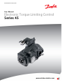
MAKING MODERN LIVING POSSIBLE
User Manual
Electronic Torque Limiting Control
Series 45
powersolutions.danfoss.com
User Manual
S45 ETL Control
Revision history
Table of revisions
2
Date
Changed
Rev
March 2015
First edition
AA
L1519202 • Rev AA • March 2015
User Manual
S45 ETL Control
Contents
Overview
Purpose of this Manual...................................................................................................................................................................5
Before You Start................................................................................................................................................................................ 5
Literature References.................................................................................................................................................................5
General Electronic Torque Control Information
PLUS+1 Compliance........................................................................................................................................................................ 6
Electric Torque Limiting Control Principle.............................................................................................................................. 6
LS Signal Line Orifice..................................................................................................................................................................7
Electronic Torque Limiting Control Characteristic............................................................................................................... 7
System Considerations when Implementing ETL
Electronic Torque Limiting and Load Sense Signals............................................................................................................9
Electronic Torque Limiting and Margin Erosion....................................................................................................................9
General Angle Sensor Information
PLUS+1 Compliance......................................................................................................................................................................10
Angle Sensor Principle................................................................................................................................................................. 10
Angle Sensor Characteristics..................................................................................................................................................... 10
J & F-Frame (45-90cc) Angle Sensor Identification Convention:............................................................................. 11
E-Frame (100-147cc) Angle Sensor Identification Convention:...............................................................................12
Angle Sensor Electrical Specifications....................................................................................................................................13
Sensor Connector and MC012 Microcontroller Pin Assignments................................................................................ 14
Angle Sensor DTM04-4P Connector Pin Assignments................................................................................................14
Pre-compiled MC012 Pin Assignments............................................................................................................................ 14
Potentiometers, Pressure Transducers, and the PumpTorqCalc Function Block....................................................15
Potentiometer............................................................................................................................................................................15
Pressure transducer................................................................................................................................................................. 15
General PLUS+1 ETL Service Tool Information
System Overview............................................................................................................................................................................18
Torque Limit Setpoint...................................................................................................................................................................18
Torque Limit Setpoint Parameters..................................................................................................................................... 18
ETL Service Tool Setup
Additional Setup
Angle Sensor Calibration.............................................................................................................................................................19
Angle Sensor Calibration Parameters................................................................................................................................20
Establish the Minimum Pump Displacement................................................................................................................. 20
Establish the Maximum Pump Displacement with Engine Off................................................................................ 21
Establish the Maximum Pump Displacement with Engine Running..................................................................... 21
Pump Setup......................................................................................................................................................................................22
Pump Setup Parameters........................................................................................................................................................ 23
Define Pump Displacement..................................................................................................................................................23
RPM Input Setup.............................................................................................................................................................................24
RPM Input Parameters............................................................................................................................................................ 24
Perform RPM Input Setup......................................................................................................................................................24
Torque Potentiometer Calibration.......................................................................................................................................... 25
Torque Potentiometer Calibration Parameters............................................................................................................. 25
Calibrate Torque Potentiometer......................................................................................................................................... 25
Pressure Sensor Setup..................................................................................................................................................................26
Pressure Sensor Setup Parameters.....................................................................................................................................26
Select Pressure Sensor Setup............................................................................................................................................... 26
Torque Limit Profile Setup..........................................................................................................................................................27
Torque Limit Profile Setup Parameters.............................................................................................................................28
Establish Torque Limit Profile with Torque Curve........................................................................................................ 28
Establish Torque Limit Profile without Torque Curve................................................................................................. 29
Adjust Torque Setpoints........................................................................................................................................................ 29
Considerations for Establishing the Torque Limit Profile.......................................................................................... 30
Boost Mode...................................................................................................................................................................................... 31
Boost Mode Parameters......................................................................................................................................................... 31
L1519202 • Rev AA • March 2015
3
User Manual
S45 ETL Control
Contents
CAN Torque Setpoint Setup.......................................................................................................................................................32
Command Filter Setup................................................................................................................................................................. 32
Command Filter Setup Parameters....................................................................................................................................34
Troubleshooting
4
Pressure Setpoint Faults.............................................................................................................................................................. 35
Electrical Interface..........................................................................................................................................................................35
L1519202 • Rev AA • March 2015
User Manual
S45 ETL Control
Overview
Purpose of this Manual
This manual is intended to be a reference for customers using Danfoss S45 Open Circuit Axial Piston
Electronic Torque Limiting (ETL) pumps in conjunction with the keyed ETL MC012 and PLUS+1® Guide
Subsystem Application Block. The setup and operation of the PLUS+1® ETL software will be illustrated
with S45 ETL pumps by utilizing the ETL PLUS+1® service screens.
Before You Start
Users setting up an ETL system with both PLUS+1® software and S45 Open Circuit ETL pumps should have
a working knowledge of basic hydraulic systems, principles, and PLUS+1® Service Tools.
Users should also have access to PLUS+1® and S45 technical literature.
Literature References
Useful technical information on pump displacements, controls specifications, software, and operating
condition requirements can be found in the following literature.
Literature references
Literature type
Literature title
Literature number
Technical Information
Series 45 Axial Piston Open Circuit
Pumps
520L0519
Service Manual
Series 45 Frame J Open Circuit
520L0607
Series 45 Frame F Open Circuit
11005158
Series 45 Frame E Open Circuit
520L0606
Parts Manuals
Repair Instructions
Series 45 Frame J
520L0585
Series 45 Frame F
11007197
Series 45 Frame E
520L0584
Series 45 Frame J Open Circuit
520L0610
Series 45 Frame F Open Circuit
520L0821
Series 45 Frame E Open Circuit
520L0609
User Guide
PLUS+1® Service Tool User Manual
L1307770
(Also found under Help on toolbar)
Data Sheet
PLUS+1® Controllers MC012-110 and
MC012-112
L1301095
Product Electrical Installation
MBS1250 Heavy Duty Pressure
Transmitter
11062087
L1519202 • Rev AA • March 2015
5
User Manual
S45 ETL Control
General Electronic Torque Control Information
PLUS+1 Compliance
All Series 45 Electric controls have met and passed the Danfoss PLUS+1 compliance standard testing, and
as such, this Series 45 control is PLUS+1 compliant. PLUS+1 compliance blocks are available on the
Danfoss website, within the PLUS+1 Guide section.
Electric Torque Limiting Control Principle
The Electronic Torque Limiting control consists of a normally closed proportional relief valve (PRV)
integrated into a Pressure Compensated/Load Sensing control. This control operates as a PC/LS control,
with the additional ability to limit load sense pressure using the integrated PRV by varying the current to
the solenoid. When combined with an angle sensor, this control allows for a PC/LS control with electronic
torque limiting.
J-frame pump with integrated ETL control
P108779
Pump torque consumption is a function of pump outlet pressure, pump displacement, and pump
mechanical efficiency. When pump mechanical efficiency is considered constant, the pump torque can
be limited when pump displacement is known and pump pressure is controlled. As pump displacement
increases, the pump outlet pressure can be limited using the PRV to result in a constant torque limit.
6
L1519202 • Rev AA • March 2015
User Manual
S45 ETL Control
General Electronic Torque Control Information
Pump outlet pressure is equal to the load sense pressure, which is limited with the PRV, plus the margin
pressure setting of the pump.
LS Signal Line Orifice
S45 Electronic Torque Limiting Controls require the use of an LS signal line orifice. The LS signal line
orifice is used to enhance system stability, as well as allow the limiting of torque throughout the full
range of pump pressure and flow. The standard 0.8 mm orifice is best suited for use in a wide variety of
applications. Please contact your Danfoss representative for further information on the availability of
additional LS signal line orifice sizes.
Electronic Torque Limiting Control Characteristic
The Electronic Torque Limiting control allows users to limit pump torque consumption electronically by
combining a pressure limiting PRV and angle sensor. This torque limit can be changed with varying
engine speeds (as shown in the Electronic Torque Limiting graph below), allowing the use of full engine
torque at all engine speeds and increasing machine productivity. A microcontroller is required to store
engine torque vs speed, receive the pump angle sensor signal, and then calculate and output the pump
outlet pressure limit. The basic torque limiting control logic for a single engine speed is shown below.
Danfoss offers a PLUS+1 subsystem application block for the Electronic Torque Limiting control option in
combination with keyed MC-12 microcontroller hardware.
Electronic Torque Limiting
Pump Pressure (bar)
300
250
200
150
Speed 1
100
Speed 2
Speed 3
50
0
0
50
100
150
200
Pump Displacement (cc)
P108783
L1519202 • Rev AA • March 2015
7
User Manual
S45 ETL Control
General Electronic Torque Control Information
Basic ETL Control Logic
350
600
500
250
400
200
300
150
200
100
100
50
0
0
5
10
15
20
25
30
35
40
45
Pump Displacement (cc)
Maximum System Pressure - ETL Active (bar)
8
Current to Valve (mA)
Maximum System Pressure (bar)
300
L1519202 • Rev AA • March 2015
Current to Valve (mA)
50
0
P108785
User Manual
S45 ETL Control
System Considerations when Implementing ETL
When setting up an ETL system to function properly, you must account for LS signal line orificing and
margin erosion.
Electronic Torque Limiting and Load Sense Signals
Danfoss PVG valves, as well as many competitor valves, are manufactured with LS signal line orifices
installed in the pump inlet (PVP) module. These orifices enhance system stability by dampening the
highest load pressure signal before it is relayed to the open circuit pump. They also help limit the amount
of flow over the load sense relief valve inside the PVP.
It is important to ensure that when using these LS line orifices the highest resolved load sense pressure is
communicated to the pump or loss of some flow sharing functionality may occur. If you experience
symptoms of loss of flow sharing, some troubleshooting steps may include removing the LS line orifice in
the valve stack, or ensuring that the LS pressure rails are connected to each other when using two or
more different valve stacks. In this way, the highest load from the system is communicated to the pump.
Electronic Torque Limiting and Margin Erosion
A potential flow sharing problem may arise when several functions are actuated at the same time and
require a high flow demand from the pump. This problem may include a loss of movement in the highest
pressure function when many functions are actuated at the same time. This problem is margin erosion.
Margin erosion is caused when margin pressure is shifted from the operator-controlled valves to the LS
signal line orifice in the S45 pump. When this margin shifts too much, the valve cannot flow share
correctly. Danfoss PVG valve groups reduce this problem with compensator valves which remain open at
a very low margin pressure. This allows more aggressive torque limiting, particularly at low engine idle
speeds where torque limiting is most critical.
In addition to using valves with superior low pressure flow sharing characteristics, it is possible to use
calculations to identify problem areas where margin erosion can become a concern. Please contact your
Danfoss representative for more information on calculating and planning for margin erosion.
L1519202 • Rev AA • March 2015
9
User Manual
S45 ETL Control
General Angle Sensor Information
PLUS+1 Compliance
The Electric Angle Sensor has met and passed the Danfoss PLUS+1 compliance standard testing, and as
such, this Angle Sensor is PLUS+1 compliant. PLUS+1 compliance blocks are available on the Danfoss
website, within the PLUS+1 Guide section.
Angle Sensor Principle
The Series 45 Angle Sensor option allows users to measure the angle of pump displacement. The angle
sensor is an electronic sensor mounted to the housing of the pump, which reads the pump stroke angle
based on the swashplate position. Interfacing with the angle sensor is achieved through a 4-pin Deutsch
DTM04-4P receptacle attached to a flexible connection cable (for a mating connector, use Deutsch® plug
DTM06-4S). The sensor is mounted to the pump within an aluminum housing to prevent magnetic
interference.
AMR Sensor
Swashplate
Magnet Carrier
Deutsch Plug
P108788
Angle Sensor Characteristics
The angle sensor package incorporates two sensor signals (primary & secondary), within a single sensor
housing. This allows for improved accuracy and troubleshooting. For the ‘Angle Sensor – Right’ order
code in the K module, the sensor is positioned according to the following conventions.
10
L1519202 • Rev AA • March 2015
User Manual
S45 ETL Control
General Angle Sensor Information
J & F-Frame (45-90cc) Angle Sensor Identification Convention:
When looking at the input shaft with the control on the ‘top’ side, the angle sensor will be viewed on the
right hand side. This convention is true for both Clockwise and Counter-clockwise rotation J & F-Frames.
86.8
[3.417]
43.5
[1.71]
36
[1.417]
37.1
[1.462]
42.5
[1.67]
30.5
[1.2]
94.1
[3.704]
29.5
[1.16]
37.1
[1.462]
87.3
[3.44]
36
[1.417]
93.6
[3.68]
J Frame Angle Sensor Position
F Frame Angle Sensor Position
P108816
This sensor location yields a unique voltage versus swashplate angle characteristic curve which is the
same for both Clockwise and Counter-clockwise rotation J & F-frames. Although each pair of curves will
be unique for individual pumps, a general example of what to expect is provided below for J & F units
with the ‘Right’ angle sensor position.
Sensor Output Voltage vs. Swashplate Angle
CW & CCW J & F-Frames (45-90cc)
Primary Output Voltage
Secondary Output Voltage
5
4.5
Sensor Output (Volts)
4
3.5
3
2.5
2
1.5
1
0.5
0
0
1
2
3
4
5
6
7
8
9
10 11 12 13 14 15 16 17 18
Swashplate Angle (Degrees)
P108817
L1519202 • Rev AA • March 2015
11
User Manual
S45 ETL Control
General Angle Sensor Information
E-Frame (100-147cc) Angle Sensor Identification Convention:
The location convention for the E-Frame angle sensor is different from that of the J & F-Frame due to a
difference in design of the endcap and servo systems. When looking at the input shaft, the angle sensor
will be positioned on the same side as the outlet port of the endcap. The outlet port of the endcap is
always the smaller of the inlet and outlet ports, indicated below. This is the ‘right side’ order code
location, even though it appears on the left hand side from a frontal view.
36
[1.42]
36
[1.42]
Outlet Port
59.4
[2.34]
126.9
[5.0]
120
[4.72]
Approximate
Wire Length
131.5
[5.18]
E Frame Angle Sensor Position
P108821
Clockwise rotation E-frames appear with the control on the top side in this view. Counter-clockwise
rotation E-Frames appear with the control on the bottom side in this view.
This sensor location yields a unique voltage versus swashplate angle characteristic curve which is
different for Clockwise and Counter-clockwise rotation E-frames. Although each pair of curves will be
unique for individual pumps, a general example of what to expect is provided below for both Clockwise
and Counter-clockwise rotation units with the Right angle sensor position.
12
L1519202 • Rev AA • March 2015
User Manual
S45 ETL Control
General Angle Sensor Information
Sensor Output Voltage vs. Swashplate Angle
CW E-Frames (100-147cc)
Primary Output Voltage
Secondary Output Voltage
5
4.5
Sensor Output (Volts)
4
3.5
3
2.5
2
1.5
1
0.5
0
0
1
2
3
4
5
6
7
8
9
10 11 12 13 14 15 16 17 18
Swashplate Angle (Degrees)
P108823
Sensor Output Voltage vs. Swashplate Angle
CCW E-Frames (100-147cc)
Primary Output Voltage
Secondary Output Voltage
5
4.5
Sensor Output (Volts)
4
3.5
3
2.5
2
1.5
1
0.5
0
0
1
2
3
4
5
6
7
8
9
10 11 12 13 14 15 16 17 18
Swashplate Angle (Degrees)
P108822
Angle sensor electrical specifications
Electrical specifications
Description
Minimum
Typical
Maximum
Unit
Note
Supply (V+)
4.75
5
5.25
Vdc
Sensor is ratiometric in the voltage range
L1519202 • Rev AA • March 2015
13
User Manual
S45 ETL Control
General Angle Sensor Information
Electrical specifications (continued)
Description
Minimum
Typical
Maximum
Unit
Note
Supply protection
—
—
28
Vdc
Sensor will switch off above 5.5 V
Supply current drawn
—
22
25
mA
Sensor supply at 5 V
Output short circuit current
(VDD to SIG 1/2 and GND to
SIG 1/2)
—
—
7.5
mA
Additional 7.5 mA for each sensor signal,
total sensor 7.5x2+22=37 mA typical for
FSO
Sensitivity in sensing range at
calibration temperature for
primary and secondary sensor
70.02
78
85.8
mV
—
Resolution
—
0.03
—
degree
11 bit output channel
Hysteresis
—
—
—
—
Design of sensor eliminates any
mechanical hysteresis
Environment temperature
range
-40 (-40)
80 (176)
104 (220)
°C (°F)
If temperature limits are exceeded, the
sensor will function at a reduced level of
performance
Operating temperature range
20 (68)
50 (122)
95 (203)
°C (°F)
Temperature of oil
Storage temperature
-40 (-40)
—
125 (257)
°C (°F)
—
Accuracy for primary and
secondary signals throughout
operating temperature range
when calibrated at 50 deg. C
—
Primary: ±0.65
Secondary: ±0.85
—
degree
Includes linearity, temperature drift, and
repeatability. Does not include the error
due to offsets and different ferrous
environment
Refresh rate of the sensor
—
—
100
μs
Internal ADC refresh rate
Sensor Connector and MC012 Microcontroller Pin Assignments
Angle Sensor DTM04-4P Connector Pin Assignments
For a mating connector, use Deutsch® plug DTM06-4S.
4
1
3
2
P108760
Pin
Assignment
1
Ground (GND)
2
Output signal 2 (SIG2) - Secondary signal
3
Output signal 1 (SIG1) - Primary signal
4
Supply (V+)
Pre-compiled MC012 Pin Assignments
12-pin connector
1
2 3 4 5 6
12 11 10 9 8 7
2200B
14
L1519202 • Rev AA • March 2015
User Manual
S45 ETL Control
General Angle Sensor Information
Pre-compiled MC012 Pin Assignments
Pin callout
Pin assignment type
ETL function assigned
C1-P1
Power ground (–)
Generic/sensor ground
C1-P2
Power supply (+)
Machine power
C1-P3
CAN (+)
CAN/J1939 High
C1-P4
CAN (–)
CAN/J1939 Low
C1-P5
AIN/CAN shield
Pressure transducer signal (optional)
C1-P6
5Vdc sensor power (+)
Angle sensor power (mandatory)
Pressure transducer power (optional)
Torque potentiometer power (optional)
C1-P7
Sensor power ground (–)
Generic/sensor ground
C1-P8
DIN/AIN/FreqIN
Angle sensor signal 1 (mandatory)
C1-P9
DIN/AIN/FreqIN
Angle sensor signal 2 (optional)
RPM speed ring pickup
Boost mode switch functionality
C1-P10
DIN/AIN/FreqIN
Potentiometer wiper (optional)
C1-P11
PWMOUT/DOUT/PVGOUT
User function
C1-P12
PWMOUT/DOUT/PVGOUT
Control coil current supply
Potentiometers, Pressure Transducers, and the PumpTorqCalc Function Block
Potentiometer
It is possible to use a potentiometer to control the torque limiting signal for ETL setup purposes. Use a 1kohm potentiometer with a 120-ohm resistor on the +V and –V ends.
Pressure transducer
Using a pressure transducer allows the ETL service tool to report actual torque and power consumed by
the S45 pump via the PumpTorqCalc Funcion Block. The PumpTorqCalc function block is an optional part
of the ETL system, and it allows the user to report real-time data on a graphical display terminal to help
equipment operators understand and improve operating efficiencies or share data between subsystems
to coordinate power sharing.
For more detailed information on the PumpTorqCalc Function Block, see Work Function Control Blocks
Library (L1313265).
Danfoss recommends using the MBS1250 Heavy Duty Pressure Transducer with a measuring range of 0
to 400 bar [5800 psi]. For information on this transducer, see MBS1250 Heavy Duty Pressure Transmitter
Product Electrical Installation (11062087).
L1519202 • Rev AA • March 2015
15
User Manual
S45 ETL Control
General PLUS+1 ETL Service Tool Information
The Electronic Torque Limiting (ETL) Service Tool is used to set up the torque limiting functionality on a
machine. See ETL Service Tool Setup on page 19 for the steps required to set up an ETL system.
Typical ETL Service Tool Screen shows a typical ETL Service Tool screen. You can navigate the Service Tool
screens in two ways.
• Diagnostic Navigator Panel (1), which allows you to view the hierarchy of all screens
• Navigation buttons (2), which give you quick access to related screens
ETL functionality is listed under Diagnostic Navigator > Parameter Functions (3).
System Overview
‒ Torque Limit Setpoint
Torque Potentiometer Calibration
Torque Limit Profile Setup
Torque Setpoint
CAN Torque Setpoint Setup
‒ Command Filter Setup
‒ Angle Sensor Calibration
‒ Boost Setup
‒ RPM Input Setup
‒ Pump Setup
‒ Pressure Sensor Setup
‒ Pressure Setpoint Faults
‒ Electrical Interface
•
User-defined toggle inputs (4) appear with a blue background.
Parameter faults (5) are shown as green, if no fault is present, and red, if a fault is present.
Each screen includes navigation links back to the System Overview (6), bounded by red.
Outputs (7) appear on all ETL Service Tool screens.
16
L1519202 • Rev AA • March 2015
User Manual
S45 ETL Control
General PLUS+1 ETL Service Tool Information
Typical ETL Service Tool Screen
Typical ETL Service Tool Outputs
Output
Description
Torque Limit Setpoint
Displays the real-time calculated torque limit for the real-time engine speed as a
percentage of maximum torque consumable by the pump. It is calculated based on the
curve fitted from the torque limit profile (discussed on torque limit profile page) or as an
input of the voltage from the Torque Potentiometer.
Engine Speed
Shows the real-time engine speed fed back from the machine. Engine speed feedback must
be wired to the microcontroller by the user using either the CAN High and CAN Low pins
(C1-P3 and C1-P4), or the RPM speed ring pickup pin (C1-P9) (see RPM Input Setup on page
24).
Pressure Setpoint
Displays the real-time system pressure currently allowed by the ETL control system.
Displayed both as a percentage of Max Pump Pressure and in bar. It is calculated by
referencing current pump displacement and engine speed (torque available at engine).
Control Current
Displays real-time current in milliamps (mA) being sent to the pump’s control solenoid from
the PLUS+1® microcontroller. A current of zero or near-zero mA indicates that the solenoid
is not being activated to limit torque.
Torque Consumed
Displays the real-time torque consumed by the pump as a calculated percentage of pump
maximum torque based on the Max Pump Displacement and Max Pump Pressure inputs.
Power Consumed
Displays the real-time power consumed by the pump as a calculated percentage of pump
maximum power based on the Max Pump Displacement, Max Pump Pressure, and Max
Pump Speed.
Displacement
Displays the real time pump displacement in both percent of maximum displacement and
cm3/rev. This displacement depends directly on the minimum and maximum displacement
calibration points.
Pressure
Indicates real-time system pressure based on a pressure transducer. Note that a pressure
transducer must be added to the system by the user for this optional functionality.
L1519202 • Rev AA • March 2015
17
User Manual
S45 ETL Control
General PLUS+1 ETL Service Tool Information
System Overview
The System Overview screen is the home screen for the ETL Service Tool. This screen shows a high-level
overview of how the S45 ETL software ties into the machine’s engine and hydraulic systems by reporting
real-time parameters.
You can also use the System Overview to do the following actions.
• Navigate to each ETL functionality to tune changes or conduct diagnostics after the general setup
• Enable or disable ETL Control using the Toggle button
ETL System Overview Screen
Torque Limit Setpoint
The Torque Limit Setpoint screen is important because it allows the user to select between two torque
limit input options (Torque Limit Profile or Torque Potentiometer).
This screen also provides quick navigation to the most frequently used setup screens.
Torque Limit Setpoint Parameters
Torque Limit Setpoint Parameters
Inputs
18
Torque Limit Input
Allows the user to select between two different forms of torque
limitation controls, Torque Profile and Potentiometer. The Torque
Profile is used when the seven limiting setpoints are finalized, and
the Potentiometer is used when first setting up ETL or conducting
diagnostics. These are discussed in detail in Torque Limit Profile
Setup on page 27.
Maximum Torque Allowed
Allows the user to de-rate the whole Torque Limit Profile by a
common factor. The software sets the default value to 100%.
L1519202 • Rev AA • March 2015
User Manual
S45 ETL Control
ETL Service Tool Setup
This section describes the ETL functions that are required for the ETL system to operate, including how to
set up each ETL function.
To set up each ETL function, you will make changes to each function's respective ETL Service Tool screen,
similar to the screen shown in Typical ETL Service Tool Screen.
The following steps are required in order for the ETL system to operate.
1. Calibrate Angle Sensor
a. Establish the Minimum Pump Displacement on page 20
b. Establish the Maximum Pump Displacement with Engine Off on page 21
or
2.
3.
4.
5.
6.
Establish the Maximum Pump Displacement with Engine Running on page 21
Define Pump Displacement on page 23
Perform RPM Input Setup on page 24
Calibrate Torque Potentiometer on page 25
Select Pressure Sensor Setup on page 26
Establish Torque Limit Profile
• Establish Torque Limit Profile with Torque Curve on page 28
or
Establish Torque Limit Profile without Torque Curve on page 29
Angle Sensor Calibration
A fundamental step in setting up ETL is to calibrate your angle sensor. The calibration will ensure accurate
angle sensor voltage readings based on maximum and minimum pump displacements (swashplate
angles).
Calibration does not inform the software what the physical maximum displacement of the pump is in
terms of engineering units. This is done in the Pump Setup Parameters screen, and the correct
calibration of the angle sensor is independent of the Max Pump Displacement input.
It is possible when calibrating the angle sensor that the Minimum Displacement Voltage is greater than
the Maximum Displacement Voltage. This is due to the different relationships between swashplate angle
and voltage for J and F-frames versus E-frame pumps. For more information, see the Angle Sensor
Characteristics on page 10.
L1519202 • Rev AA • March 2015
19
User Manual
S45 ETL Control
ETL Service Tool Setup
Angle Sensor Calibration Screen
Angle Sensor Calibration Parameters
Angle Sensor Calibration Parameters
Calibration
Inputs
Faults
Minimum Pump Displacement
Records the angle sensor signal voltage that corresponds to the
pump’s lowest displacement condition
Maximum Pump Displacement
Records the angle sensor signal voltage that corresponds to the
pump’s highest displacement condition
C1p08-Primary Signal
Displays the real-time voltage signal from the primary sensor
pickup
C1p09-Secondary Signal
Displays the real-time voltage signal from the secondary sensor
pickup, if enabled (optional)
Calibration/Parameter Faults
Minimum/Maximum displacement not calibrated
Invalid setup/calibration
Parameter out of range
Sensor Input Faults
Signal 1 input too low/high
Signal 1 input at Sensor Power/Ground
Redundant signal indicates error
Establish the Minimum Pump Displacement
To establish the minimum displacement of the pump, you must operate the pump at either the Low
Pressure Standby Condition (LPSB) or the High Pressure Standby Condition (HPSB).
For the best results, calibrate and compare using both LPSB and HPSB to achieve the lowest (or highest,
for CW E-frame units) captured voltages.
20
L1519202 • Rev AA • March 2015
User Manual
S45 ETL Control
ETL Service Tool Setup
It is important to compare the minimum displacement voltage readings at both LPSB and HPSB.
Generally, the swashplate angle is lower at LPSB because there are lower leakages at lower pressures, so
lower displacements are required to make up the leakages. This is not true when some flow is allowed
past the main valve block at LPSB. Then, HPSB conditions become preferred. Although the leakages are
higher at higher pressures, the increase in flow due to leakages is lower than the flow allowed by the
main valve.
1. Set the engine at full operating speed.
The engine must be operated at full speed to prevent an inaccurate displacement reading.
2. If the ETL is not disabled in the System Overview screen, toggle ETL Control to Disabled.
The control current should approximate 0 mA.
3. Operate the pump at one or both of the following conditions.
Condition
When to use
Low Pressure Standby
Condition (LPSB)
Use when the machine’s main valve block completely shuts off flow to any
downstream components (zero flow needed by machine functions/valves from
pump)
High Pressure Standby
Condition (HPSB)
Use when the machine’s main valve block does not completely shut off flow to all
downstream components (some small flow needed by machine functions/valves
from pump at all times, even with no operator command)
a) If using LPSB, let the machine stand at full engine speed without operating any functions.
This allows the pump to de-stroke naturally because no flow is commanded from the pump, and
system pressures will be only slightly higher than the pump’s LS setting.
b) If using HPSB, operate a machine function over a hard-stop and reach full pressure compensator
(PC) setting with system pressure.
This allows the pump to de-stroke by porting high pressure oil to servo.
From the Angle Sensor Calibration screen while maintaining either LPSB or HPSB:
4. Click Minimum Pump Displacement > Capture Voltage.
Establish the Maximum Pump Displacement with Engine Off
1. Turn off the machine.
2. Momentarily jog the starter to turn the pump shaft a few revolutions, without actually running the
engine.
This allows the pump’s swashplate to return to its naturally spring biased full-stroke position by
overcoming residual pressure and friction in the swashplate and servo system.
From the Angle Sensor Calibration screen:
3. Click Maximum Pump Displacement > Capture Voltage.
Establish the Maximum Pump Displacement with Engine Running
The engine must be operated at full speed to prevent an inaccurate displacement reading.
1. Operate the pump in a full displacement, full flow, and low load machine condition.
a) Operate engine at full operating speed.
b) Command a single high flow function or multiple machine functions simultaneously while
remaining below the pump’s pressure compensator setting (low system pressure).
Do not reach or exceed the pressure compensator setting or the pump will begin to de-stroke
and reduce its displacement and render a bad maximum displacement reading.
From the Angle Sensor Calibration screen:
2. Click Maximum Pump Displacement > Capture Voltage.
L1519202 • Rev AA • March 2015
21
User Manual
S45 ETL Control
ETL Service Tool Setup
Pump Setup
The pump setup function defines the pump displacement in PLUS+1® software. It also sets the maximum
system pressure and maximum pump speed to calculate the maximum pump torque and power.
Coil current thresholds are also set up based on the user's inputs.
Pump Setup Screen
22
L1519202 • Rev AA • March 2015
User Manual
S45 ETL Control
ETL Service Tool Setup
Pump Setup Parameters
Pump Setup Parameters
Inputs
Faults
Max Pump Pressure
Defines the maximum desired system pressure created by the pump, in
bar. This must be less than or equal to the Pressure Compensator (PC)
setting. This software setting DOES NOT override the pump’s factory set
mechanical Pressure Compensator setting. If the Max Pump Pressure is
higher than the PC setting, the pump will default to the physical PC
pressure of the pump and the ETL system will not function correctly.
Max Pump Speed
Calculates power consumed by the pump. Generally, the highest engine
operation speed of the machine should be used. See Series 45 Pumps
Technical Information (520L0519) for allowed pump operating speeds in
order to ensure conformance to recommended continuous operation
speeds. This input does not limit physical pump speed in any way.
Max Pump
Displacement
Defines the true maximum displacement of the pump in terms of cm3/rev
and correlates it to the Maximum Captured Voltage.
Also known as nominal pump displacement, it can be determined by the
pump’s model code.
LS pressure setting
Defines the margin setting of the pump, in bar. This must be equal to the
LS pressure setting as defined from the factory. This may be found on the
pump's identification tag.
Threshold current
Defines the minimum current required for active torque limiting in the
control. It is based on the Max Pump (PC) Pressure, LS Pressure Setting,
and 12- vs. 24-volt coil characteristics. This is an interpolated value that
references control pressure vs. current curves.
Parameter input faults
Max Pump Pressure out of range
Max Pump Speed out of range
Max Pump Displacement out of range
Input faults
Displacement value too high or low
Speed value too high or low
Pressure value too high or low
Define Pump Displacement
From the Pump Setup screen:
1. Set Pump Max Pressure to the desired maximum operating pressure.
The Pump Max Pressure setting must not exceed the Pressure Compensator (PC) setting of the
pump. It should be equal to or less than the PC setting, or else the system will lose power because the
pump will need to relieve pressure in a constant manner.
2. Set LS Pressure Setting to the pump's factory LS margin pressure.
3. Set Max Pump Speed to the maximum operating speed at which the pump will operate.
In general, you should use the highest engine operation speed of the machine. See Series 45 Pumps
Technical Information (520L0519) for allowed pump operating speeds to conform to the
recommended continuous operation speeds.
4. Set Max Pump Displacement to the physical maximum displacement of the pump in units of cm3/
rev.
5. Set Threshold Current.
a) Toggle Coil Setup to the correct coil voltage.
b) Set Max Pump (PC) Pressure and LS Pressure Setting.
The Recommended Threshold field will display the recommended threshold.
c) Select Use Recommended.
The recommended current threshold will transfer to the Threshold Current field.
Advanced users may reference a control pressure vs. current curve and enter their own threshold to
create a custom offset for the threshold setting.
L1519202 • Rev AA • March 2015
23
User Manual
S45 ETL Control
ETL Service Tool Setup
RPM Input Setup
The RPM input limits the torque throughout an engine’s usable speed range. To set up this limit, you
must select the proper speed input, either CAN bus speed pickup or speed ring pulse pickup.
RPM Input Setup Screen
RPM Input Parameters
RPM Input Parameters
Inputs
Speed Input
Pulse Per Revolution
Faults
Toggle switches between two different inputs: CAN bus and Speed ring
pulse pickup
Sets the number of pulses per revolution of the Hall Effect Sensor when
Speed Ring is selected
C1p09 - MFIn Freq
Displays the frequency at which the speed ring sensor is sensing pulses
Parameter input faults
PPR parameter is out of range (>10,000)
Frequency is too high (>50,000)
Frequency is too low (=0)
Perform RPM Input Setup
From the RPM Input Setup screen:
1. Toggle your desired input to use for the engine speed pickup.
• Speed ring
•
CAN bus
2. If a hall effect/speed ring type is used, indicate the number of pulses per revolution in Pulse Pickup
Calibration > Pulse Per Revolution.
The engine speed output will read the real-time speed when set up.
24
L1519202 • Rev AA • March 2015
User Manual
S45 ETL Control
ETL Service Tool Setup
Torque Potentiometer Calibration
This section applies only if a potentiometer is used for ETL setup.
A potentiometer greatly reduces the Torque Limit Profile setup time by allowing quick adjustments to
the actual torque limit at any engine speed condition. In order for a potentiometer to be used for this
functionality, it must first be calibrated.
Torque Potentiometer Calibration Screen
Torque Potentiometer Calibration Parameters
Torque Potentiometer Calibration Parameters
Calibration
C1p10 - Voltage
Indicates the real-time signal voltage being input from the Torque
Potentiometer
Minimum Captured Voltage
Displays the minimum captured voltage created by the
potentiometer
Maximum Captured Voltage
Displays the maximum captured voltage created by the
potentiometer
Auto Calibration Toggle
Enables or disables the auto calibration feature
Clear Calibration
Clears the minimum and maximum captured voltages from the
previous calibration to establish a new calibration
Calibrate Torque Potentiometer
1. Connect a potentiometer to the indicated pins in the MC012 pin out.
From the Torque Potentiometer Calibration screen:
2. Toggle the auto calibration to Auto Cal Enabled.
This calibrates the potentiometer.
L1519202 • Rev AA • March 2015
25
User Manual
S45 ETL Control
ETL Service Tool Setup
3. Turn the potentiometer from lock to lock in a steady manner.
The auto calibration feature will automatically capture the minimum and maximum allowable
voltages registered while the Auto Cal is enabled. The proper voltage range will be attained when
using a 1k-ohm potentiometer with 120-ohm resistors on both the +V and -V ends.
4. After the minimum and maximum voltages are captured, toggle the auto calibration to Auto Cal
Disabled.
5. If the calibration did not cover the full range of the potentiometer, or if you need to use a new
potentiometer, click Clear Calibration.
This deletes the previously captured voltages to capture a new calibration.
The minimum and maximum voltages of the potentiometer will not be 0V or 5V. This is not allowed
for fault monitoring purposes.
Pressure Sensor Setup
The Pressure Sensor Setup screen allows the user to enable the use of a system pressure transducer. A
pressure transducer is helpful to diagnose the system and calculate power consumed by the pump.
Pressure Sensor Setup Screen
Pressure Sensor Setup Parameters
Pressure Sensor Setup Parameters
Inputs
Pressure Sensor Enable Enables or disables in-line pressure transducer functionality
Faults
Parameter input faults
Pin value too high (at sensor power)
Pin value too low (at sensor ground)
Select Pressure Sensor Setup
26
L1519202 • Rev AA • March 2015
User Manual
S45 ETL Control
ETL Service Tool Setup
1. After system pressure functionality is desired, hook up the recommended pressure transducer to the
recommended pins.
For pinout, see Pre-compiled MC012 Pin Assignments on page 14.
From the Pressure Sensor Setup screen:
2. Toggle Pressure Sensor Enable to Enabled.
Torque Limit Profile Setup
The Torque Limit Profile is the heart of an ETL system. It is what defines how a machine reacts to torque
loads, and it has an infinite number of tuning possibilities. It allows you to define how the system limits
torque consumed by the open circuit hydraulic system.
The most basic torque profile will reference a graph of engine torque available vs. engine speed from the
engine manufacturer. However, this basic profile may not always be the best profile, and such detailed
engine information might be difficult to obtain.
It is important to realize that the user can tune the reactivity of the ETL system by how closely the 7 input
points match the actual torque available from the engine. Torque values which exactly match the
available torque from the engine may yield a system which allows for noticeable engine speed reactions
(engine bog or droop) as torque limiting takes over. This generally occurs because the pump’s input
torque requirements may increase much more rapidly than the engine’s torque output.
However, torque values which are set slightly lower than the actual available engine torque provide
some margin between the limited torque and the actual torque. This combats any reactivity from the
engine at all, and gives the operator the setup with the lowest potential for noticeable engine speed
changes.
The desired amount of engine reaction is subjective and can vary for different applications.
You can create a Torque Limit Profile with or without a torque curve. A torque curve is highly
recommended for best optimization, but it is not necessary.
L1519202 • Rev AA • March 2015
27
User Manual
S45 ETL Control
ETL Service Tool Setup
Torque Limit Profile Setup Screen
Torque Limit Profile Setup Parameters
Torque Limit Profile Setup Parameters
Inputs
Faults
Speed Inputs 1–7
These speed inputs correspond to 7 engine speed points on a torque
curve for which torque is to be limited
Torque Inputs 1–7
These torque inputs correspond to the 7 engine speed points on a torque
curve for which torque is to be limited
Parameter inputs
Speed [N] is less than or equal to Speed [N-1]
Speed [N], out of range
Torque [N], out of range
Inputs
Actual engine input speed value too low or high
Establish Torque Limit Profile with Torque Curve
The following steps establish a torque limit profile if a known engine torque curve is available.
From the Torque Limit Profile Setup screen:
1. Set the engine Speed Inputs (Speed 1–7) at which you wish to limit torque.
For example, set the lowest engine idle speed, highest engine idle speed, and five equally spaced
points between the two.
2. Set the Torque Inputs (Torque 1–7).
To do this, normalize the engine's torque values to reflect the pump's maximum consumable torque.
That is, divide the available engine torque by the pump’s maximum consumable torque to get a
Pump Torque Setpoint percentage.
Pump Torque Setpoint n speed [%] =
28
L1519202 • Rev AA • March 2015
Engine Available Torque n speed
Pump Torque Consumed Max Pump Pressure, Displacement
User Manual
S45 ETL Control
ETL Service Tool Setup
For example, if your engine’s available torque at 950 rpm is 196 N-m, and a 75cc J-frame pump
operating at a pressure limit of 240 bar will consume 302 N-m of torque, then 196 / 302 = 65%. This is
the Pump Torque Setpoint required at 950 rpm. Continue using this method for all 7 torque setpoints.
After establishing a torque limit profile, the torque setpoints may still require adjustment to achieve the
desired engine/machine reactivity. See Adjust Torque Setpoints on page 29.
Establish Torque Limit Profile without Torque Curve
The following steps establish a torque limit profile if an engine torque curve is not available. It uses a
guess-and-check method.
From the Torque Limit Profile Setup screen:
1. Set the engine Speed Inputs (Speed 1–7) at speeds which you wish to limit torque.
For example, set the lowest engine idle speed, highest engine idle speed, and five equally spaced
points between the two.
2. Set the Torque Inputs (Torque 1–7) .
The following steps are one suggestion.
a) Pick the lowest engine speed and set the machine at this condition.
b) Operate the machine through various high-torque consumption cycles.
c) Adjust the torque limit setpoint to achieve the desired level of torque limiting (some, or virtually
none, engine reaction/bog).
The reactiveness is affected by how close the pump’s allowed torque is relative to the engine’s
available torque.
After establishing a torque limit profile, the torque setpoints may still require adjustment to achieve the
desired engine/machine reactivity. See Adjust Torque Setpoints on page 29.
Adjust Torque Setpoints
After establishing a torque limit profile, the torque setpoints may still require adjustment to achieve the
desired engine/machine reactivity.
Adjust the torque setpoints using one of the following options.
Option
Torque Inputs
Steps
1. Set the Torque Inputs (Torque 1–7).
2. Download and check.
Torque Setpoint Curve
1. Click and drag the points in Torque Setpoint Curve.
2. Download and check.
Torque Potentiometer
1. Use a torque potentiometer to adjust the torque setpoints while operating the
machine.
2. Enter the setpoints into the Torque Limit Profile.
3. Download and check.
The torque potentiometer has been shown to greatly reduce the process time to adjust torque
setpoints and fine tune the torque profile.
L1519202 • Rev AA • March 2015
29
User Manual
S45 ETL Control
ETL Service Tool Setup
Considerations for Establishing the Torque Limit Profile
•
•
•
The amount of torque limiting required may be objective or subjective
‒ Objective examples
Killing the machine vs. not killing the machine
Not allowing the engine to droop more than ‘XXXX’ rpm below desired idle speed
Not allowing the engine to droop to a certain sound criteria
Allowing the engine to droop to a certain sound criteria
Not allowing the pump to drop below a certain flow requirement based on a pressure criteria
(necessary function speed under no load)
‒ Subjective examples
Operator must be able to experience some engine reactivity to perceive machine work
Operator skill allows for smaller margin between available engine torque and pump torque
consumed
Operator does not want machine to slow down too much
The amount of torque consumed by the open circuit pump system does not account for the torque
consumed by the closed circuit pump system
‒ Propel vs. work functions
A specific machine function may require more or less torque depending on environmental conditions
‒ Cold weather vs. hot weather oil viscosity
For questions on setting up the Torque Limit Profile for your machine, consult your Danfoss
representative.
30
L1519202 • Rev AA • March 2015
User Manual
S45 ETL Control
Additional Setup
The features in this section are not required for an ETL system to function. These features enhance or
adjust system performance and functionality.
Boost Mode
Boost mode, or ETL override, allows the user to configure an operator interface to enable or disable ETL.
One example is a momentary switch incorporated into an interface such as a joystick.
The pre-keyed MC012 does not allow both the torque potentiometer and the boost mode functionality
to be used at the same time. To use boost mode, the potentiometer functionality must be disabled, and
vice versa. The engine will not be protected from stalling while boost mode is enabled.
One benefit of boost mode includes artificially creating a pressure setting that is lower than the pump’s
physical pressure compensator setting. As a result, you can achieve extra pressure capability on
command by enabling or disabling ETL and creating an extra power level.
Boost Setup Screen
Boost Mode Parameters
Boost Mode Parameters
Boost Enable
Allows or prevents the use of Boost Mode. When Disabled, Boost Mode cannot be used
even if an operator interface is present. If Enabled, Boost Mode can be used when not
using the Torque Potentiometer functionality.
Input
Boost mode can be configured with a switch that is either Pull Up or Pull Down in
the electrical schematic. This toggle switches the logic between the two options.
Status
Indicates whether Boost Mode is Off (ETL enabled) or Boost Enabled (ETL disabled).
L1519202 • Rev AA • March 2015
31
User Manual
S45 ETL Control
Additional Setup
CAN Torque Setpoint Setup
In CAN setpoint enable mode, the S45 pump responds to auxiliary command messages.
When the CAN setpoint is enabled, you can remotely send a torque setpoint to the pump by identifying
an address on the CAN.
Please consult with your Danfoss representative for more information on setting up torque setpoints with
CAN messaging.
CAN Torque Setpoint Setup Screen
Command Filter Setup
The Command Filter Setup screen allows for possible filtering of control current signals if there are
pressure oscillations. The ETL system, by default, sets the command control filter to zero, which means it
is disabled.
If the command control filter is used, the filter values can be increased until the unwanted oscillations
reach an acceptable level.
Command filter setup is only necessary if unwanted instability or oscillations occur when ETL is active.
The time constant sets the cutoff frequency for a first order low pass exponential filter.
Determining the frequency of oscillations can help give you a starting point for the time constant: fc = 1/
(2*pi*t).
32
L1519202 • Rev AA • March 2015
User Manual
S45 ETL Control
Additional Setup
If the ETL control produces unwanted oscillations, and all time constant values are set to zero, use the
following table and the Command Filter Setup screen to reduce oscillations.
Are oscillations occurring when the load
is increasing?
Yes
Increase the Increasing input.
No
Leave the Increasing input at zero.
Are oscillations only occurring when the Yes
load is decreasing at high engine speed?
No, there is no oscillation when the load is
decreasing at high engine speed
No, oscillations occur when the load is
decreasing at both high and low speeds
L1519202 • Rev AA • March 2015
•
•
•
•
•
•
Set the High Speed input to the affected engine speed.
Increase the High Speed Decreasing input.
Leave the High Speed Decreasing input at zero.
Set the High Speed input to the high engine speed.
Ensure the High Speed and Low Speed inputs match the
engine tuning speeds before adjusting filter inputs.
Set the High Speed Decreasing and Low Speed
Decreasing inputs to the high and low engine setpoints.
33
User Manual
S45 ETL Control
Additional Setup
Command Filter Setup Screen
For questions on system stability and tuning with Command Filter time constants, consult your Danfoss
representative.
Command Filter Setup Parameters
Command Filter Setup Parameters
Inputs
Faults
Low Speed
Speed at which Low Speed Decreasing time constant is used for
filtering the torque setpoint output
High Speed
Speed at which High Speed Decreasing time constant is used for
filtering the torque setpoint output
Low Speed Decreasing
Low pass filter time constant to limit decrease in pressure setpoint. The
actual used filter value is a scaled between High Speed Decreasing and
Low Speed Decreasing, depending on speed. Associated with Low
Speed.
High Speed Decreasing
Low pass filter time constant to limit decrease in pressure setpoint. The
actual used filter value is a scaled between High Speed Decreasing and
Low Speed Decreasing, depending on speed. Associated with High
Speed.
Increasing
Low pass filter time constant to limit increase in pressure setpoint.
Parameter Fault
High Speed out of range
Low Speed out of range
Input Fault
Displacement too low/high
Speed to low/high
Torque Demand too low/high
34
L1519202 • Rev AA • March 2015
User Manual
S45 ETL Control
Troubleshooting
Pressure Setpoint Faults
The Pressure Setpoint Faults screen is used for troubleshooting.
Pressure Setpoint Faults Screen
Electrical Interface
The Electrical Interface screen allows you to troubleshoot the electrical interface, including the status of
the input pins, output pins, and supply/sensor power.
L1519202 • Rev AA • March 2015
35
User Manual
S45 ETL Control
Troubleshooting
ETL Electrical Interface Screen
36
L1519202 • Rev AA • March 2015
User Manual
S45 ETL Control
L1519202 • Rev AA • March 2015
37
User Manual
S45 ETL Control
38
L1519202 • Rev AA • March 2015
User Manual
S45 ETL Control
L1519202 • Rev AA • March 2015
39
Products we offer:
•
•
•
•
•
•
•
•
•
•
•
•
•
•
•
•
Bent Axis Motors
Closed Circuit Axial Piston
Pumps and Motors
Displays
Electrohydraulic Power
Steering
Electrohydraulics
Danfoss Power Solutions is a global manufacturer and supplier of high-quality hydraulic and
electronic components. We specialize in providing state-of-the-art technology and solutions
that excel in the harsh operating conditions of the mobile off-highway market. Building on
our extensive applications expertise, we work closely with our customers to ensure
exceptional performance for a broad range of off-highway vehicles.
We help OEMs around the world speed up system development, reduce costs and bring
vehicles to market faster.
Danfoss – Your Strongest Partner in Mobile Hydraulics.
Hydraulic Power Steering
Go to www.powersolutions.danfoss.com for further product information.
Integrated Systems
Wherever off-highway vehicles are at work, so is Danfoss. We offer expert worldwide support
for our customers, ensuring the best possible solutions for outstanding performance. And
with an extensive network of Global Service Partners, we also provide comprehensive global
service for all of our components.
Joysticks and Control
Handles
Microcontrollers and
Software
Open Circuit Axial Piston
Pumps
Orbital Motors
Please contact the Danfoss Power Solution representative nearest you.
PLUS+1® GUIDE
Proportional Valves
Sensors
Steering
Transit Mixer Drives
Comatrol
www.comatrol.com
Schwarzmüller-Inverter
www.schwarzmuellerinverter.com
Local address:
Turolla
www.turollaocg.com
Valmova
www.valmova.com
Hydro-Gear
www.hydro-gear.com
Daikin-Sauer-Danfoss
www.daikin-sauer-danfoss.com
Danfoss
Power Solutions (US) Company
2800 East 13th Street
Ames, IA 50010, USA
Phone: +1 515 239 6000
Danfoss
Power Solutions GmbH & Co. OHG
Krokamp 35
D-24539 Neumünster, Germany
Phone: +49 4321 871 0
Danfoss
Power Solutions ApS
Nordborgvej 81
DK-6430 Nordborg, Denmark
Phone: +45 7488 2222
Danfoss
Power Solutions
(Shanghai) Co., Ltd.
Building #22, No. 1000 Jin Hai Rd
Jin Qiao, Pudong New District
Shanghai, China 201206
Phone: +86 21 3418 5200
Danfoss can accept no responsibility for possible errors in catalogues, brochures and other printed material. Danfoss reserves the right to alter its products without notice. This also applies to
products already on order provided that such alterations can be made without changes being necessary in specifications already agreed.
All trademarks in this material are property of the respective companies. Danfoss and the Danfoss logotype are trademarks of Danfoss A/S. All rights reserved.
L1519202 • Rev AA • March 2015
www.danfoss.com
© Danfoss A/S, 2015