1
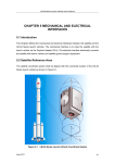
LS+ LambdaSonde Plus LAMBDA METER USER MANUAL Version 3.0 • www.lsplus.eu LS+ LambdaSonde Kit Components 18mm x 1.5mm Boss and Plug P/N: LS-104 Power Red: +12 V Power Black, White: Grounds Lambda Sensor P/N: LS-103 Both ground wires must run separate until connected to ground point (i.e. don’t extend with single wire) Wiring Harness, P/N: LS-102 (2.4m to sensor, 2.4m to power) Calibration Potentiometer Display Module P/N: LS-101 Analog Output Pink: 0-5 V Signal (Vout) Brown: Signal Ground (Lambda = 0,14 x Vout + 0,6 Error=0,2V, Warmup=0,3V) WARNINGS The Lambda sensor gets very hot when power is applied and it stays hot for a while after power is disconnected. It can burn you and potentially ignite combustible vapors. Be careful when handling the sensor. Do not open or modify the display module. Do not apply excessive voltage (more than 28V DC) to the harness. Do not modify the wiring harness. If the wiring harness is damaged, do not use it. Replace it. Do not open or modify the Lambda sensor. Do not attempt to clean the Lambda sensor with compressed air or any solvent. If you do this, it is highly likely that the sensor will begin to give inconsistent readings. Installing and Calibrating the LS+ Introduction The LS+ is a tool to measure the air-fuel ratio (Lambda) delivered to carbureted and fuel injected performance engines. Its measurement range is 0,65 to 1,3 Lambda. For maximum Lambda sensor life, the sensor must be powered when in the exhaust of a running engine. LS+ Installation The Lambda sensor should be located between 300 and 1200mm from the engine and upstream of any catalyst device if so equipped. The closer the sensor is to the engine, the more likely it will be overheated (max. gas temp. 850 C), possibly shortening its life. The further it is from the engine, the more likely condensed water will get into the sensor and thermally shock it, again possibly shortening its life. The sensor should be mounted at least ten exhaust diameters upstream of the exhaust exit. If the sensor is mounted between one and ten exhaust diameters from the exhaust exit, the Lambda measured will be leaner (i.e. higher) than the actual Lambda at low engine speeds (i.e. less than 3000 rpm) due to air reversion effects at the exit of the exhaust system. This is particularly acute with single and two-cylinder engines. In turbocharged applications, it is recommended to install the sensor downstream of the turbine. This is due to the fact that the high pressures before the turbine can distort the Lambda reading. Apply the same installation guidelines as described above, but take into consideration that the sensor needs to be downstream of the turbine. Make sure there are no leaks in the exhaust system, as this will create an artificially lean Lambda reading. Also, install the sensor upstream of any factory air-injection if so equipped, as this too will cause a false lean reading. The sensor boss requires a 19mm hole in the exhaust. A step drill or hole saw may be used. Weld the sensor boss to the exhaust so that it will position the sensor in the upper half of the exhaust. This is to avoid liquid fuel or condensed water from getting inside the sensor and thermally shocking it. After welding the sensor boss to the exhaust, run an M18 x 1.5mm tap or thread cleaner through the boss to remove any thread distortion. If this is not done, the sensor’s threads may be damaged during installation or removal. Apply a small amount of anti-seize on the threads and tighten the sensor to 20~25 Nm. Caution must be taken not to overtighten the sensor. Unless you are permanently installing the unit as a constant Lambda monitoring device, you will be installing and removing the sensor frequently. The more you over-tighten the sensor, the more the threads will deform each time you install it and make it that much more difficult to reinstall the next time. During a reinstallation, if the sensor shows any resistance to being screwed back into the boss, run the tap or thread cleaner through the boss, clean the threads of the sensor with a fine wire brush, and apply a small amount of anti-seize on the threads before installation. If the threads on the sensor are damaged, run the sensor into a die. The display module has an operating temperature range of -40 to 85 C and is splashproof but not 100% water-proof. Mount it accordingly. The display module and the harness should be kept away from ignition systems and the harness should be routed away from the exhaust system and moving engine components. The quality of the Lambda measurement depends on the quality of the power you supply the LS+ with. The ground terminal should be connected directly to the battery’s negative terminal or the body of the vehicle (if metal). The power terminal should have 11 to 28V DC attached (via a switch or relay) whenever the engine is running. If the sensor is not powered when the engine is running, sensor life will be shortened. The LS+ (including sensor) draws less than 2 amps. Before the LS+ is used for the first time, or for the first time before a new Lambda sensor is used, it should be calibrated. (see section LS+ Calibration) Analog Output The LS+ has a 0 to 5V linear analog output signal (Vout) that is proportional to Lambda according to the formula below and it also has indication for the status of the sensor and controller: Lambda = 0,14 x Vout + 0,6 Error: Vout=0.2 +/- 0.040 Warmup: Vout=0.3 +/- 0.040 The output is available from short pink (Vout) and brown (signal ground) wires that can be pulled out of the harness sleeve at the controller end of the harness. This output can be fed to a data acquisition system or engine controller. It is extremely important to note that the signal ground (brown) is at the ground potential of the point where the power ground of the harness is attached. The power ground point used by the LS+ must be the same power ground point used by the data acquisition system or engine controller. If it is not, the above formula will not work. Before attaching the analog output wires of the LS+ to your data acquisition or engine controller, measure the voltage between the brown (signal ground) wire and the point on the data acquisition system or engine controller where that signal ground wire is about to be attached. Have the LS+ powering the sensor and have the data acquisition system or engine controller powered on (have the engine running if the LS+ is to drive the engine controller) while measuring. If this voltage measured is less than 0.010 V then there is no problem. If it is greater than 0.010 V, then you will have to relocate the power ground of the LS+ or the data acquisition system or the engine controller ground so that the voltage measured is less than 0.010 V. LS+ Calibration The procedure to calibrate the LS+ is as follows: 1. Connect the harness to the control module and the Lambda sensor. With power disconnected from the harness and the sensor removed from the exhaust, hold the sensor by its wires letting it hang free in air. You cannot reliably calibrate the LS+ with the sensor mounted in the exhaust of an engine, even if the engine has been off for several days. 2. Attach power to the harness. In about 10 seconds, you will start to notice the Lambda sensor getting hot. Use CAUTION, the sensor can burn you. 3. Wait 5 minutes. This is to allow the sensor to reach operating temperature. NOTE: If the sensor is “smoking” or smells, it is not being exposed to pure calibration air. Under such circumstances, leave it powered in air for 45 minutes to burn off any condensed material. Do not spray the sensor with compressed air or any solvent. If you do this, it is highly likely that the sensor will begin to give inconsistent readings. 4. Turn the calibration knob on the back of the display head until the display reads “CAL-”. If the display reads “Air_” when the sensor is in air, turn the knob clockwise until the display reads “CAL-“. If the display reads “Air-–“ when the sensor is in air, turn the knob counterclockwise unit the display reads “CAL-“. 5. Disconnect the power from the harness. When the Lambda sensor cools down, install it in the exhaust and do not touch the calibration knob until the next time you calibrate the LS+. It is impossible to predict how often the LS+ needs to be calibrated without knowing the conditions under which the Lambda sensor was used. However, here are some calibration rules-of-thumb: The first time before a new sensor is used: calibrate. For every 1000m. change in altitude: calibrate. For race engines: calibrate before every tune session. For wild, street performance engines: calibrate once every week of use on the street. For mild street engines: calibrate once every month of use on the street. For use with leaded fuel: calibrate once every hour. Experience will teach you if you need to shorten or lengthen these times by how much you had to turn the calibration knob to recalibrate. If you did not have to turn the calibration knob at all, you can lengthen the time between calibrations. The LS+ has been designed to extend the Lambda sensor’s life as long as possible. However, since sensor life depends on sensor operating conditions, it impossible to predict sensor life without knowing the conditions under which the Lambda sensor was used. Certainly, leaded fuel will shorten the sensor’s life. However, there is a statistical component to sensor life. For example, a plug may foul and the sensor may be sprayed with raw fuel and thus be thermally shocked. Therefore, the Lambda sensor should be considered an expendable part; a cost of tuning, just like gasoline and your time. Some tuners will never kill a sensor. Some tuners will kill two sensors a race season. Some tuners will kill a sensor every tuning session or race. If you are not using the sensor to tune the engine, take it out. Replacement Lambda sensors are available from your LS+ distributor or you can use a Bosch LSU4.2 sensor you acquired on your own. An optional connector kit (P/N LS105, see Appendix) is available that allows you to attach your own sensor. If you make a mistake and miswire the sensor, you will likely damage the sensor, the controller, and your reputation with us. Using the LS+ to Tune Engines for Racing Applications People who tune spark ignition engines for racing applications are concerned with decreased lap times, faster e.t.s, and higher speeds. Once an engine is physically built, the fuel delivery (i.e. jetting or fuel pulse duration), and spark timing are the two principle tuning parameters used to optimize the engine for the type of racing it will participate in. One way to tune the fuel delivery is to do a lot of track testing. However, because the relationship between Lambda measurements and maximum horsepower, best throttle response, engine life, and best fuel economy are well known, it is faster to first tune to specific Lambdas and then to use actual track performance for final fuel delivery adjustments. For most spark ignition engines, there is a specific small window of Lambda in which maximum horsepower and best throttle response will be found. For gasoline, that range is about Lambda 0,85 to 0,89. For reasons such as engine life and fuel economy, some engines are not operated within that range. Here are some examples: At high load conditions, air-cooled engines are often operated at a Lambda as low as 0,68 in order to reduce engine temperatures that may lead to engine damage. At high load conditions, turbocharged engines are often operated at a Lambda as low as 0,68-0,78 (sometimes even less) in order to reduce engine and turbocharger temperatures which may lead to engine and turbine damage. When mounting the sensor on a turbocharged application, it is recommended that the sensor be installed downstream of the turbine. Engines operated at loads beyond their original design or at their maximum load for periods longer than they were designed for may be operated at a Lambda as low as 0,68 in order to reduce engine temperatures that may lead to engine damage. In racing where fuel stops are made, engines can be operated at a Lambda greater than 0,89 at light loads in order to improve fuel economy. Fuel economy is maximized at a Lambda of about 1,1. However, at these leaner Lambdas (i.e. higher numbers), internal engine temperatures will increase and this may lead to engine damage at high loads. With low octane fuels, engines are often operated at a Lambda less than 0,85 in order to suppress detonation that may lead to engine damage. Engines that have a centralized fuel delivery system (i.e. a carburetor) or badly shaped manifolds may have some cylinders operating at a Lambda greater or less than the engine average. The fuel delivery and induction should be tuned so that the average of the cylinders is between 0,85 and 0,89, and to avoid a specific cylinder(s) from operating at a lean Lambda that could lead to overheating or detonation. In summary: If you have a water-cooled, naturally aspirated engine, start with a Lambda of 0,85 and tune from there. For forced induction, start at 0,68 and tune from there. “Tune from there” means adjusting the Lambda and then testing for benefits such as decreased lap times, faster e.t.s, and higher speeds while watching for issues leading to unsatisfactory engine life or fuel economy. Always keep in mind that leaner Lambdas (i.e. higher numbers) increase engine temperatures and if caution is not taken, can lead to engine damage at high engine loads. The preceding discussion pertains to race engines operating under race conditions. When race engines are idling, a Lambda less than 0,89 can lead to plug fouling or bad environment. Often increasing the idle Lambda will eliminate plug fouling. At idle, the engine is operating far below its maximum temperature and pressure limits, so increasing idle Lambda is unlikely to lead to engine damage at idle unless the engine is wildly misfiring. With carburetors, idle Lambda adjustments will influence off-idle Lambda and may cause detonation during initial throttle opening. Therefore and especially with carburetors, the choice of idle Lambda will be based on tradeoffs between spark plug fouling, idle smoothness, off-idle Lambda, and detonation. The final choice of idle Lambda may be between 0,89 and 1,1. Often it is closer to 0,89 than 1,1. Using the LS+ to Tune Engines for Performance Street Applications Performance street engines should be tuned the same way as race engines are except during non-WOT (non-wide open throttle) operation, the Lambda should be increased. The reasoning here is that it makes no sense to pollute the air and waste fuel unless maximum engine power is required. For non-WOT and non-idle conditions, a Lambda of about 1 will often give satisfactory performance, will pollute less, and will use less fuel. LS+ Troubleshooting If you cannot calibrate the LS+ or if the display shows “Sen#” (“#” is a trouble code number), you should: 1. Check if the sensor is attached 2. Check if the wiring harness is damaged 3. If steps 1. and 2. show no problems, replace the Lambda sensor. It has reached its limit for useful life. If the display shows “Bat_”, the supply voltage is too low (below 11V). If the display shows “Bat¯“, the supply voltage is too high (above 28V). If the display reads “0,65”, the Lambda is 0,65 or less. If the display reads “1,3”, the Lambda is 1,3 or more. LS+ Specifications Lambda Range 0,65 ~ 1,3 Lambda Analogue output 0-5V with status indication Accuracy Within 0,01 Lambda Supply Voltage DC 11V ~ 28V Sensor Tightening Torque 20-25 Nm. Controller Temperature Tolerance -40 to 85°C Absolute Maximum Exhaust Temperature 850° C Dimensions Controller, excluding protusions: 86 x 67 x 32 mm Controller weight: 120g Harness length: Sensor side 2,4m, Power side 2,4m Compatible Fuel Types Gasoline, alcohol (methanol), ethanol, CNG, LPG, propane LS+ Product Warranty LSPLUS warrants that the products, which it sells to the distributor, seller, reseller, or customer, shall be free from defects in workmanship and materials within a period of sixty (60) days from the delivery thereof to the aforementioned parties. This does not apply to products that have been modified, altered, abused, damaged during transit, or subjected to conditions in excess of their intended environment. Due to the nature of the product, there is no warranty on Lambda sensor life. LSPLUS not be liable for any economic damages or losses resulting from the improper use of its products. Appendix Optional P/N LS-105: Connector Kit for Replacement Bosch LSU 4.2 Sensor Deutsch 0416-204-2005 (dummy plug) Deutsch DTM04-6P Deutsch WM6P (terminal lock) Deutsch 0460-202-2031 (gold terminals) Terminal No. Wire Color 4 1 2 3 5 6 Spare Terminal Plug GRAY WHITE RED BLACK YELLOW Crimp Here Prefer Deutsch Tool HDT-48-00 Assembly instructions Crimp the supplied terminals to the sensor wires (you can’t solder them since the wires are made out of stainless steel) and install the terminals in the connector housing so that the colors on the sensor wires flow into the same colors on the LS+ harness (i.e. red to red, …). www.lsplus.eu