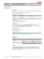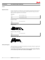
1
MAKING MODERN LIVING POSSIBLE
Service Manual
Open Circuit Axial Piston Pumps
Series 45 E Frame
powersolutions.danfoss.com
Service Manual
Series 45 E Frame Open Circuit Pumps
Revision history
Table of revisions
2
Date
Changed
Rev
August 2015
Danfoss Layout
0300
October 2012
add new control types
AG
November 2010
new last page
AE
February 2010
fix Osaka address
AD
March 2008
add displacement limiter specs
AC
March 2005
First edition
A
520L0606 • Rev 0300 • August 2015
Service Manual
Series 45 E Frame Open Circuit Pumps
Contents
Introduction
Technical specifications
Features
Pressure measurement
Initial Start-Up Procedures
Fluid and Filter Maintenance
Troubleshooting
Overview..............................................................................................................................................................................................5
Safety precautions............................................................................................................................................................................5
Unintended machine movement..........................................................................................................................................5
Flammable cleaning solvents................................................................................................................................................. 5
Fluid under pressure.................................................................................................................................................................. 5
Personal safety............................................................................................................................................................................. 5
Symbols used in Danfoss literature............................................................................................................................................6
General description......................................................................................................................................................................... 7
System circuit.....................................................................................................................................................................................8
General specifications.....................................................................................................................................................................9
Type of mounting....................................................................................................................................................................... 9
Auxiliary mounting pad options............................................................................................................................................9
Control options............................................................................................................................................................................9
Port options...................................................................................................................................................................................9
Direction of rotation...................................................................................................................................................................9
Installation position....................................................................................................................................................................9
Technical specifications............................................................................................................................................................9
Hydraulic parameters................................................................................................................................................................... 11
Inlet pressure..............................................................................................................................................................................11
Pressure compensator valve setting..................................................................................................................................11
Case pressure............................................................................................................................................................................. 11
Hydraulic fluid ...........................................................................................................................................................................11
Temperature range (1)............................................................................................................................................................. 11
Fluid viscosity.............................................................................................................................................................................11
Filtration ......................................................................................................................................................................................11
Displacement limiter.....................................................................................................................................................................12
Auxiliary mounting pads............................................................................................................................................................. 12
Input shafts.......................................................................................................................................................................................13
Control options...............................................................................................................................................................................13
General......................................................................................................................................................................................... 13
PC control.................................................................................................................................................................................... 13
LS control.....................................................................................................................................................................................14
Electric Proportional Controls.............................................................................................................................................. 15
Electric On/Off Controls..........................................................................................................................................................15
Electronic Torque Limiting Controls (ETL)....................................................................................................................... 16
PLUS+1® Compliance......................................................................................................................................................... 16
Required tools................................................................................................................................................................................. 18
Port locations and gauge installation.....................................................................................................................................18
General...............................................................................................................................................................................................19
Start-up procedure........................................................................................................................................................................ 19
Recommendations........................................................................................................................................................................ 20
Excessive noise and/or vibration..............................................................................................................................................21
Actuator response is sluggish....................................................................................................................................................21
System operating hot...................................................................................................................................................................21
Low pump output flow................................................................................................................................................................22
Pressure or flow instability..........................................................................................................................................................22
System pressure not reaching PC setting............................................................................................................................. 23
High inlet vacuum..........................................................................................................................................................................23
520L0606 • Rev 0300 • August 2015
3
Service Manual
Series 45 E Frame Open Circuit Pumps
Contents
Adjustments
Minor repair
4
PC control..........................................................................................................................................................................................24
LS control.......................................................................................................................................................................................... 26
Shaft seal replacement.................................................................................................................................................................28
Removal........................................................................................................................................................................................28
Installation...................................................................................................................................................................................28
Auxiliary pads.................................................................................................................................................................................. 29
Removal........................................................................................................................................................................................29
Installation...................................................................................................................................................................................29
LS and PC Controls.........................................................................................................................................................................30
Disassembly................................................................................................................................................................................30
Inspection....................................................................................................................................................................................31
Reassembly................................................................................................................................................................................. 31
Electric Controls..............................................................................................................................................................................33
Disassembly................................................................................................................................................................................33
Inspection....................................................................................................................................................................................33
Reassembly................................................................................................................................................................................. 34
Electronic Torque Limiting Control......................................................................................................................................... 35
Repair............................................................................................................................................................................................ 35
Angle Sensor....................................................................................................................................................................................36
Removal........................................................................................................................................................................................36
Inspection....................................................................................................................................................................................36
Reassembly................................................................................................................................................................................. 37
Servo Control Orifice.....................................................................................................................................................................38
Plug and fitting sizes and torques........................................................................................................................................... 39
520L0606 • Rev 0300 • August 2015
Service Manual
Series 45 E Frame Open Circuit Pumps
Introduction
Overview
This manual includes information for the installation, maintenance, and minor repair of the Series 45
frame E open circuit axial piston pumps. The manual includes a description of the units and their
individual components, troubleshooting information, and minor repair procedures. Performing
installation, maintenance, and minor repair of Series 45 E frame axial piston pumps according to the
procedures in this manual will not affect your warranty.
Performing minor repairs requires the unit to be removed from the vehicle/machine. Thoroughly clean
the unit before beginning maintenance, or repair activities. Since dirt and contamination are the greatest
enemies of any type of hydraulic equipment, follow cleanliness requirements strictly. This is especially
important when changing the system filter and when removing hoses or plumbing.
A worldwide network of Danfoss Authorized Service Centers (ASCs) is available for major repairs. Major
repairs require the removal of the unit’s endcap, which voids the warranty unless done by an ASC.
Danfoss ASCs are trained by the factory and certified on a regular basis. You can locate your nearest ASC
using the distributor locator at www.powersolutions.danfoss.com
Safety precautions
Always consider safety precautions before beginning a service procedure. Protect yourself and others
from injury. Take these general precautions whenever servicing a hydraulic system.
Unintended machine movement
W
Warning
Unintended movement of the machine or mechanism may cause injury to the technician or bystanders.
To protect against unintended movement, secure the machine or disable / disconnect the mechanism
while servicing.
Flammable cleaning solvents
W
Warning
Some cleaning solvents are flammable. To avoid possible fire, do not use cleaning solvents in an area
where a source of ignition may be present.
Fluid under pressure
W
Warning
Escaping hydraulic fluid under pressure can have sufficient force to penetrate your skin causing serious
injury and/or infection. This fluid may also be hot enough to cause burns. Use caution when dealing with
hydraulic fluid under pressure. Relieve pressure in the system before removing hoses, fittings, gauges, or
components. Never use your hand or any other body part to check for leaks in a pressurized line. Seek
medical attention immediately if you are cut by hydraulic fluid.
Personal safety
W
Warning
Protect yourself from injury. Use proper safety equipment, including safety glasses, at all times.
520L0606 • Rev 0300 • August 2015
5
Service Manual
Series 45 E Frame Open Circuit Pumps
Introduction
Symbols used in Danfoss literature
WARNING may result in injury
Tip, helpful suggestion
CAUTION may result in damage to product or
property
Lubricate with hydraulic fluid
Reusable part
Apply grease / petroleum jelly
Non-reusable part, use a new part
Apply locking compound
Non-removable item
Inspect for wear or damage
Option - either part may exist
Clean area or part
Superseded - parts are not interchangeable
Be careful not to scratch or damage
Measurement required
Note correct orientation
Flatness specification
Mark orientation for reinstallation
Parallelism specification
Torque specification
External hex head
Press in - press fit
Internal hex head
Pull out with tool – press fit
Torx head
Cover splines with installation sleeve
O-ring boss port
Pressure measurement/gauge location or
specification
The symbols above appear in the illustrations and text of this manual. They are intended to communicate
helpful information at the point where it is most useful to the reader. In most instances, the appearance
of the symbol itself denotes its meaning. The legend above defines each symbol and explains its purpose.
6
520L0606 • Rev 0300 • August 2015
Service Manual
Series 45 E Frame Open Circuit Pumps
Introduction
General description
Danfoss Series 45 E frame open circuit piston pumps convert input torque into hydraulic power.
Rotational force is transmitted through the input shaft to the cylinder block. The input shaft is supported
by tapered roller bearings at the front and rear of the pump and is splined into the cylinder block . A lipseal at the front end of the pump prevents leakage where the shaft exits the pump housing. The spinning
cylinder block contains nine reciprocating pistons. Each piston has a brass slipper connected at one end
by a ball joint. The slippers are held to the swashplate by the spring retainer and block spring. The block
spring also holds the cylinder block to the valve plate. The reciprocating movement of the pistons occurs
as the slippers slide against the inclined swashplate during rotation. Via the valve plate, one half of the
cylinder block is connected to pump inlet and the other half to pump outlet. As each piston cycles in and
out of its bore, fluid is drawn from the inlet and displaced to the outlet thereby imparting power into the
system circuit. A small amount of fluid is allowed to “leak” from the cylinder block / valve plate and
slipper / swashplate interfaces for lubrication and cooling. Case drain ports are provided to return this
fluid to the reservoir.
The volume of fluid displaced into the system circuit is controlled by the angle of the swashplate. The
swashplate is forced into an inclined position (into stroke) by the bias piston and spring. The servo piston
opposes the action of the bias piston and spring forcing the swashplate out of stroke when hydraulic
pressure in the control circuit rises above the spring force.
The pump control, by varying the pressure at the servo piston, controls the displacement of fluid in the
system circuit. Controls designed for Pressure Compensation (PC) or Load Sensing (LS) are available. For a
detailed description of control operation, refer to Control options on page 13.
Pump and control sectional view
LS control
(attached to endcap)
LS adjustment
LS spool
PC adjustment
PC spool
Lifting lug
Servo piston guide
Adjustable
displacement
limiter
Servo piston
Slipper retainer
Shaft seal
Valve plate
Cylinder block
Block
spring
Input shaft
Tapered
roller
bearing
Tapered
roller
bearing
Swashplate
Slipper
Bias spring
Bias piston guide
520L0606 • Rev 0300 • August 2015
Bias piston
Piston
P104001E
7
Service Manual
Series 45 E Frame Open Circuit Pumps
Introduction
System circuit
The pump receives fluid directly from the reservoir through the inlet line. A screen placed in the inlet
protects the pump from large contaminants. The output of the pump is directed to a PVG-32 multisection load sensing directional control valve which directs fluid to the actuators in the system. Fluid
returning from the system is cooled by a heat exchanger and cleaned by a filter before returning to the
reservoir.
The speed of the actuators in the system depends on the volume of fluid being provided by the pump.
The operating pressure varies depending on actuator load, but is limited to an adjustable maximum
setting by the PC section of the pump control and by a system relief valve integrated into the side
module of the PVG valve.
The position of the PVG valve sets the demand for flow in the system and communicates this to the
pump control by means of a hydraulic signal (load sense signal). The pump will provide as much flow to
the system as it demands while limiting the maximum pressure. Therefore flow and pressure in the
system are compensated to meet requirements.
Full available flow is a function of pump displacement, operating speed, and efficiency. Refer to Series 45
Axial Piston Open Circuit Pumps Technical Information, 520L0519 for details.
Pictorial circuit diagram
E Frame Series 45
open circuit axial
piston pump with
load sensing control
Double-acting cylinder
PVG 32
multi-section
load
sensing
control
valve
Bi-directional
gear motor
System pressure
Servo pressure
Reservoir
Filter
Heat exchanger
Actuator pressure
Load sense pressure
Actuator return
Suction / case drain /
system return
P104 045E
8
520L0606 • Rev 0300 • August 2015
Service Manual
Series 45 E Frame Open Circuit Pumps
Technical specifications
General specifications
Type of mounting
SAE-C mounting flange.
Auxiliary mounting pad options
SAE-A, SAE-B, SAE-B-B, SAE-C, SAE C-C
Control options
PC: Pressure Compensator
LS: Load Sensing (with PC)
Port options
Inlet and system ports:
SAE flanged ports, code 61 Inlet Code 62 outlet.
•
•
Axial (end) ports or radial (side) ports.
All other ports:
SAE straight thread O-ring boss.
•
Direction of rotation
Clockwise or counterclockwise.
Installation position
Installation position is discretionary. To satisfy inlet pressure conditions, it is recommended that the
pump always be located below the lowest level of hydraulic fluid in the reservoir. The housing must
always be filled with hydraulic fluid.
Technical specifications
Features and options
Feature
Unit
E100B
E130B
E147C
Maximum Displacement
cm³ [in³]
100 [6.10]
130 [7.93]
147 [8.97]
Flow at rated speed (theoretical)
l/min
[US gal/min]
245
[64.7]
286
[75.6]
309
[81.6]
Input torque at maximum displacement (theoretical)
N•m/bar
[lbf•in/1000 psi]
1.592
[972]
2.069
[1263]
2.340
[1428]
Mass moment of inertia of internal rotating
components
kg•m²
[slug•ft²]
0.0128
[0.0094]
0.0128
[0.0094]
0.0128
[0.0094]
Weight
kg [lb]
51.3 [113]
Axial ports
Radial ports
Model
54.9 [121]
Rotation
Clockwise, Counterclockwise
Mounting
SAE-C
Auxiliary mounting
SAE-A, SAE-B, SAE-BB, SAE-C, SAE-CC
System ports (type)
4-bolt split flange
520L0606 • Rev 0300 • August 2015
9
Series 45 E Frame Open Circuit Pumps
Service Manual
Technical specifications
Features and options (continued)
Feature
Unit
Model
E100B
System ports (location)
E130B
E147C
Axial, Radial
Control types
PC, Remote PC, LS, LS with internal bleed
Shafts
Splined
13-tooth, 14-tooth, 17-tooth
Straight
Ø 38.08 mm [1.5 in]
Displacement limiters
Optional, adjustable
Ratings
Rating
Input speed¹
Working pressure
Units
E100B
E130B
E147C
500
500
500
continuous
2450
2200
2100
maximum
2880
2600
2475
minimum
continuous
min-1 (rpm)
bar [psi]
maximum
External shaft loads
External moment (Me)
N•m [lbf•in]
Thrust in (Tin), out (Tout)
N [lbf]
310 [4495]
260 [3770]
400 [5800]
350 [5075]
455 [4030]
360 [3190]
396 [3500]
2846 [640]
1735 [390]
2113 [475]
6672 [1500]
7117 [1600]
77 200
32 700
21 600
at 210 bar [3045 psi]
19 800
8400
5500
at 260 bar [3770 psi]
9700
4116
2700
5400
2300
—
at 140 bar [2030 psi]
B10 hours
at 310 bar [4495 psi]
Mounting flange load
moments
310 [4495]
400 [5800]
7740 [1740]
Thrust out (Tout)
Bearing life
Model
Vibratory (continuous)
N•m [lbf•in]
Shock (max)
1920 [17 000]
6779 [60 000]
(1) Input speeds are valid at 1 bar absolute [0 in Hg vac] inlet pressure. See Inlet pressure vs. speed charts
in the Series 45 Technical Information Manual 520L0519.
10
520L0606 • Rev 0300 • August 2015
Service Manual
Series 45 E Frame Open Circuit Pumps
Technical specifications
Hydraulic parameters
Inlet pressure
Minimum pressure, continuous = 0.8 bar absolute [6.7 inch Hg vac] (at reduced maximum pump speed)
Minimum pressure, cold start = 0.5 bar absolute [15.1 inch Hg vac]
Pressure compensator valve setting
Setting
100 and 130 cc
Minimum
100 bar [1450 psi]
Maximum
310 bar [4495 psi]
147 cc
260 bar [3770 psi]
Case pressure
Maximum continuous: 0.5 bar [7 psi] Above inlet
Intermittent: 2 bar [29 psi] Cold start
Hydraulic fluid
Refer to Danfoss publication Fluids and Filtration BLN-9887 or 520L0463. For information on
biodegradable fluids refer to Biodegradable Hydraulic Fluids 520L0465. See Fluid and Filter Maintenance
on page 20 for recommended fluid and filter change intervals.
Temperature range (1)
Intermittent (cold start): - 40° C [- 40° F]
Continuous: 82° C [180° F]
Maximum (2): 104° C [220° F]
(1) Hydraulic fluid viscosity must be maintained within the prescribed limits.
(2) As measured at the hottest point in the system, e.g. drain line.
Fluid viscosity
Viscosity limits
Rating
ν continuous
ν intermittent
mm2/s (cSt) [SUS]
minimum
9 [58]
maximum
110 [500]
minimum
6.4 [47]
maximum (cold start)
1000 [4700]
Filtration
Required cleanliness level: ISO 4406 Class 18/13 or better. Refer to Danfoss publications Fluids and
Filtration BLN-9887 or 520L0463 and Design Guidelines for Selecting and Maintaining the Required
Hydraulic Fluid Cleanliness 520L0465. See Fluid and Filter Maintenance on page 20 for recommended
fluid and filter change intervals.
520L0606 • Rev 0300 • August 2015
11
Service Manual
Series 45 E Frame Open Circuit Pumps
Features
Displacement limiter
Frame E Series 45 pumps are available with an optional adjustable maximum displacement limiter. The
adjustable stop limits the pump’s maximum displacement. The displacement change per turn of the
displacement limiter adjustment screw is shown below.
Setting range
100 cc
40 to 100 cm³ [2.44 to 6.1 in³]
130 cc
70 to 130 cm³ [4.27 to 7.93 in³]
147 cc
87 to 147 cm³ [5.31 to 8.97 in³]
Displacement change
100 cc
8.4 cc/rev [0.513 in³/rev]
130 cc
147 cc
Displacement limiter
P107 779E
Displacement change - older models
100 cc
6.5 cc/rev [0.397 in³/rev]
130 cc
147 cc
Displacement limiter - older models
P104 046
Auxiliary mounting pads
Auxiliary mounting pads are available for all radial ported Series 45 pumps. These pads are typically used
for mounting auxiliary hydraulic pumps.
Since the auxiliary pad operates under case pressure, you must use an O-ring to seal the auxiliary pump
mounting flange to the pad. Oil from the main pump case lubricates the drive coupling. For details refer
to Series 45 Axial Piston Open Circuit Pumps Technical Information 520L0519.
12
520L0606 • Rev 0300 • August 2015
Service Manual
Series 45 E Frame Open Circuit Pumps
Features
Auxiliary pad options
P104 047
Input shafts
Series 45 E frame pumps are available with a variety of splined and straight keyed shafts. For information
on shafts refer to Series 45 Axial Piston Open Circuit Pumps Technical Information 520L0519.
Control options
The Series 45 Frames E have three possible control options, a Load Sensing (LS) control with Pressure
Compensator (PC), a PC only control, or an electric control.
General
The bias piston and spring (1) acts at all times to push the swashplate (2) to maximum angle causing the
pump to stroke. The servo piston (3) acts against the bias piston and spring to reduce the swashplate
angle causing the pump to destroke. Swashplate angle determines pump outlet flow. The pump control,
depending on conditions in the system circuit, sets swashplate angle by metering system pressure to the
servo piston.
Cross-section pump
3
1
2
P104 048
Bias spring and servo piston set swashplate position
PC control
The PC control design maintains a constant pressure in the hydraulic circuit as flow varies. The PC control
modulates pump flow accordingly to maintain system pressure at the PC setting as the PC adjusting plug
(4) and spring (5) defines.
When system pressure, acting on the non-spring end of the PC spool (6), overcomes the force of the PC
spring, the spool shifts porting system pressure to the servo piston and the swashplate angle decreases.
520L0606 • Rev 0300 • August 2015
13
Service Manual
Series 45 E Frame Open Circuit Pumps
Features
When system pressure drops below the PC setting, the PC spring shifts the spool in the opposite
direction connecting the servo piston to pump case and the swashplate angle increases. The swashplate
is maintained at whatever angle is required to keep system pressure at the PC setting.
Cross-section PC control
4
6
5
P104 049
PC spool shifts to port system pressure to servo piston
LS control
The LS control design matches pump flow with system demand. The LS control senses the flow demand
of the system as a pressure drop across the External Control Valve (ECV). As the ECV opens and closes, the
pressure delta across the valve changes. When opening, the delta decreases. When closing, the delta
increases. The LS control then increases or decreases pump flow to the system until the pressure delta
becomes equal to the LS setting as defined by the LS adjusting plug (7) and spring (8).
The LS control consists of two spool valves that connect the servo piston either to pump case or system
pressure. The PC spool (6) controls the pressure-compensating function of the control as previously
described. The LS spool (9) controls the load-sensing function. The PC spool has priority over the LS spool.
Through internal porting, system pressure (upstream of ECV) is applied to the non-spring end of the LS
spool, and through hydraulic line connected at port X, LS pressure (downstream of ECV) is applied to the
spring end. This arrangement allows the LS spool to act on the delta between system pressure and LS
pressure. The LS spring sets the threshold of operation (LS setting).
Because the swashplate is biased to maximum angle, the pump attempts to deliver full flow to the
hydraulic system. When the flow being delivered exceeds demand, the pressure delta across the ECV is
great enough to overcome spring force and shift the LS spool porting system pressure to the servo
piston. The pump de-strokes reducing flow until the delta across the ECV becomes equal to the LS
setting. When flow being delivered is less than demand, the delta across the ECV drops below the LS
setting and the LS spring shifts the spool connecting the servo piston to pump case. The pump strokes
increasing flow until the delta across the ECV becomes equal to the LS setting.
When the external control valve is placed in neutral, it connects the LS signal line to drain. With no LS
pressure acting on the non-spring end of the LS spool, the pump adjusts stroke to whatever position
necessary to maintain system pressure at the LS setting. The pump is now in standby mode.
Because of the series arrangement of the LS and PC spools, the PC spool will override the LS spool. If at
any time system pressure reaches the PC setting, the PC spool will shift blocking the passage that
connects the LS spool with the servo piston and porting system pressure to the servo piston causing the
pump to destroke.
Typical load-sensing control valve
Load
2 pressure
Return
pressure
Tank
Load sense
pressure
14
System
2 pressure
520L0606 • Rev 0300 • August 2015
P101 665E
Service Manual
Series 45 E Frame Open Circuit Pumps
Features
Pressure drop across external control valve defines system demand
Cross-section LS control
Spring Spring
guide
Spool
Plug
Plug
Spool
LS spring
LS adjusting
plug
PC adjusting
plug
Spring
Spring (PC heavy)
guide
P104 051
LS spool shifts to port system pressure to servo piston
Electric Proportional Controls
Plus+1TM Compliance
All Series 45 Electric controls have met and passed the Danfoss PLUS+1® compliance standard testing,
and as such, this Series 45 control is PLUS+1® compliant. PLUS+1® compliance blocks are available on the
Danfoss website, within the PLUS+1 Guide section.
Electric Proportional Control Principle
The Electric Proportional Control consists of a proportional solenoid integrated into a Remote Pressure
Compensated control. This control allows the pump to be operated at any pressure limit between the
Load Sense and Pressure Compensation settings by varying the current sent to the solenoid.
Electric On/Off Controls
PLUS+1TM Compliance
All Series 45 Electric controls have met and passed the Danfoss PLUS+1® compliance standard testing,
and as such, this Series 45 control is PLUS+1® compliant. PLUS+1® compliance blocks are available on the
Danfoss website, within the PLUS+1 Guide section.
520L0606 • Rev 0300 • August 2015
15
Service Manual
Series 45 E Frame Open Circuit Pumps
Features
Electric On/Off Control Principle
The Electric On-Off Control consists of an On/Off solenoid integrated into a Remote Pressure
Compensated control. This control allows the pump to be operated at either the Load Sense pressure
setting when “On”, or the Pressure Compensation pressure setting when “Off”.
Electronic Torque Limiting Controls (ETL)
PLUS+1® Compliance
All Series 45 Electric controls have met and passed the Danfoss PLUS+1® compliance standard testing,
and as such, this Series 45 control is PLUS+1® compliant. PLUS+1® compliance blocks are available on the
Danfoss website, within the PLUS+1 Guide section.
Electric Torque Limiting Control Principle
The Electronic Torque Limiting control consists of a normally closed proportional relief valve (PRV)
integrated into a Pressure Compensated/Load Sensing control. This control operates as a PC/LS control,
with the additional ability to limit load sense pressure using the integrated PRV by varying the current to
16
520L0606 • Rev 0300 • August 2015
Service Manual
Series 45 E Frame Open Circuit Pumps
Features
the solenoid. When combined with an angle sensor, this control allows for a PC/LS control with electronic
torque limiting.
B
M1
M2
M4
L2
S
L1
P104 025
Pump torque consumption is a function of pump outlet pressure, pump displacement, and pump
mechanical efficiency. When pump mechanical efficiency is considered constant, the pump torque can
be limited when pump displacement is known and pump pressure is controlled. As pump displacement
increases, the pump outlet pressure can be limited using the PRV to result in a constant torque limit.
Pump outlet pressure is equal to the load sense pressure, which is limited with the PRV, plus the margin
pressure setting of the pump.
520L0606 • Rev 0300 • August 2015
17
Service Manual
Series 45 E Frame Open Circuit Pumps
Pressure measurement
Required tools
The service procedures described in this manual can be performed using common mechanic’s hand
tools. Special tools, if required are shown. Calibrate pressure gauges frequently to ensure accuracy. Use
snubbers to protect gauges.
Port locations and gauge installation
The illustration below shows gauge port locations. Recommended pressure gauges and fittings are in the
table.
Gauge and port information
Port
Purpose
Range of gauge
Fitting
M1, M2
System pressure
0-300 bar [0-5000 psi]
9/16 - 18 O-ring fitting
M4
Servo pressure
0-300 bar [0-5000 psi]
9/16 - 18 O-ring fitting
L1, L2
Case drain
0-300 bar [0-5000 psi]
1-1/16 - 12 O-ring fitting
X1
LS signal
0-300 bar [0-5000 psi]
7/16 - 20 O-ring fitting (tee
into LS signal line)
Gauge port locations
X
X
S
X
M4
B
M2
S&B
L1
M1
L2
P104 052
18
520L0606 • Rev 0300 • August 2015
Legend
B
=
S
=
L1, L2 =
X
=
M1
=
M2
=
M4
=
Main pressure line
Suction line
Case drain lines
Load sensing pressure port
CW endcap system pressure gauge*
Gauge port for port B*
Gauge port — servo pressure
*Same pressure
Service Manual
Series 45 E Frame Open Circuit Pumps
Initial Start-Up Procedures
General
Follow this procedure when starting-up a new Series 45 installation or when restarting an installation in
which the pump has been removed.
W
Warning
Unintended movement of the machine or mechanism may cause injury to the technician or bystanders.
To protect against unintended movement, secure the machine or disable/disconnect the mechanism
while servicing.
Prior to installing the pump, inspect for damage incurred during shipping. Make certain all system
components (reservoir, hoses, valves, fittings, heat exchanger, etc.) are clean prior to filling with fluid.
Start-up procedure
1. Connect the pump to the prime mover. Ensure that pump shaft is properly aligned with the shaft of
the prime mover.
C
Caution
Incorrect shaft alignment may result in damage to drive shaft, bearings, or seal which can cause
external oil leakage.
2. Fill the reservoir with recommended hydraulic fluid. Always filter fluid through a 10 micron filter
pouring into the reservoir. Never reuse hydraulic fluid.
3. Fill the main pump housing with clean hydraulic fluid. Pour filtered oil directly into the upper most
case drain port.
4. Fill the inlet line leading from the pump to the reservoir. Check the inlet line for properly tightened
fittings and be certain it is free of restrictions and air leaks.
5. To ensure the pump stays filled with oil, install the case drain line in the upper most case drain port.
6. Install a gauge at the system pressure gauge port to monitor system pressure during start up.
Follow recommendations in the vehicle/machine operator’s manual for prime mover start up
procedures.
7. While watching the pressure gauge installed at the system pressure gauge port, jog the prime mover
or run at the lowest possible speed until system pressure builds to normal levels (minimum 11 bar
[160 psi]). Once system pressure is established, increase to full operating speed. If system pressure is
not maintained, shut down the prime mover, determine cause, and take corrective action. Refer to
the Troubleshooting chapter.
8. Operate the hydraulic system for at least fifteen minutes under light load conditions.
9. Check and adjust control settings as necessary after installation. Refer to the Adjustments chapter.
10. Shut down the prime mover and remove the pressure gauge. Replace the plug at port the system
pressure gauge port.
11. Check the fluid level in the reservoir; add clean filtered fluid if necessary.
The pump is now ready for operation.
520L0606 • Rev 0300 • August 2015
19
Service Manual
Series 45 E Frame Open Circuit Pumps
Fluid and Filter Maintenance
Recommendations
To ensure optimum life of Series 45 products, perform regular maintenance of the fluid and filter.
Contaminated fluid is the main cause of unit failure. Take care to maintain fluid cleanliness when
servicing.
Check the reservoir daily for proper fluid level, the presence of water, and rancid fluid odor. Water in the
fluid may be noted by a cloudy or milky appearance or free water in the bottom of the reservoir. Rancid
odor indicates the fluid has been exposed to excessive heat. Change the fluid immediately if these
conditions occur. Correct the problem immediately.
Change the fluid and filter per the vehicle/machine manufacturer’s recommendations or at these
intervals:
Change the fluid more frequently if it becomes contaminated with foreign matter (dirt, water, grease,
etc.) or if the fluid is subjected to temperature levels greater that the recommended maximum.
Dispose of used hydraulic fluid properly. Never reuse hydraulic fluid.
Change filters whenever the fluid is changed or when the filter indicator shows that it is necessary to
change the filter. Replace all fluid lost during filter change.
Fluid and filter change interval
20
Reservoir type
Maximum change interval
Sealed
2000 hours
Breather
500 hours
520L0606 • Rev 0300 • August 2015
Service Manual
Series 45 E Frame Open Circuit Pumps
Troubleshooting
Excessive noise and/or vibration
Item
Description
Action
Check fluid level in reservoir.
Insufficient hydraulic fluid causes cavitation.
Fill the reservoir to proper level.
Check for air in system.
Air in system causes noisy, erratic control.
Purge air and tighten fittings. Check inlet for
leaks.
Check pump inlet pressure/vacuum.
Improper inlet conditions cause erratic behavior
and low output flow.
Correct pump inlet pressure / vacuum
conditions. Refer to the Hydraulic Parameters
topic.
Inspect shaft couplings.
A loose or incorrect shaft coupling causes
excessive noise and/or vibration.
Repair or replace coupling and ensure that
correct coupling is used.
Check shaft alignment.
Misaligned shafts create excessive noise and/or
vibration.
Correct shaft misalignment.
Hydraulic fluid viscosity above acceptable limits.
Hydraulic fluid viscosity above acceptable limits
or low fluid temperature will not allow the pump
to fill or control to operate properly.
Allow system to warm up before operating, or
use fluid with the appropriate viscosity grade for
expected operating temperatures. See Hydraulic
Fluids and Lubricants Technical Information
Manual, 520L0463.
Item
Description
Action
Check external system relief valve setting.
Low external relief valve setting slows down
system.
Adjust external relief valve setting following
manufacturer’s recommendations. External relief
setting must be above PC setting to operate
properly.
Check PC and LS control setting.
Low PC setting prevents the pump from
Adjust PC and LS setting. Refer to the
achieving full stroke. Low LS setting limits output Adjustments chapter.
flow.
Check LS control signal pressures.
Incorrect LS signal will not allow pump to
operate correctly.
Inspect system to ensure that proper LS signal
transmit to pump.
Internal system leaks.
Worn internal parts don’t allow the pump to
operate properly.
Refer to Authorized Service Center for required
repair.
Hydraulic fluid viscosity above acceptable limits.
Hydraulic fluid viscosity above acceptable limits
or low fluid temperature will not allow the pump
to fill or control to operate properly.
Allow system to warm up before operation or sue
fluid with the appropriate viscosity grade for
expected operating temperatures. See Hydraulic
Fluids and Lubricants Technical Information
Manual, 520L0463.
Check external system valving.
Malfunctioning valving may not allow system to
respond properly.
Repair or replace system valving as required.
Check pump case pressure.
High case pressure causes the system to be
sluggish.
Correct case drain line restrictions.
Check pump inlet pressure/vacuum.
High inlet vacuum causes low output flow.
Correct inlet pressure conditions.
Item
Description
Action
Check fluid level in reservoir.
Insufficient volume of hydraulic fluid will not
meet cooling demands of system.
Fill reservoir to proper level. Verify proper size of
reservoir.
Inspect heat exchanger. Check air flow and input
air temperature for the heat exchanger.
Insufficient air flow, high input air temperature,
or undersized heat exchanges will not meet
cooling demands of the system.
Clean, repair, or replace heat exchanger as
required. Verify proper size of heat exchanger.
Actuator response is sluggish
System operating hot
520L0606 • Rev 0300 • August 2015
21
Service Manual
Series 45 E Frame Open Circuit Pumps
Troubleshooting
Item
Description
Action
Check external system relief valve setting.
Fluid passing through relief valve adds heat to
system.
Adjust external system relief valve setting
following manufacturer’s recommendations.
External relief valve setting must be above PC
setting for proper operation.
Check pump inlet pressure/vacuum.
High inlet vacuum adds heat to system.
Correct inlet pressure/vacuum conditions.
Item
Description
Action
Check fluid level in reservoir.
Insufficient hydraulic fluid will limit output flow
and cause internal damage to pump.
Fill the reservoir to proper level.
Hydraulic fluid viscosity above acceptable limits.
Fluid viscosity above acceptable limits or low
fluid temperature will not allow the pump to fill
or control to operate properly.
Allow system to warm up before operating, or
use fluid with the appropriate viscosity grade for
expected operating temperatures. See Hydraulic
Fluids and Lubricants Technical Information
Manual, 520L0463.
Check external system relief valve setting.
Eternal relief valve set below PC setting causes
low output flow.
Adjust external relief valve following
manufacturer’s recommendation. External relief
valve setting must be above PC setting to
operate properly.
Check PC and LS control setting.
Low PC setting prevents the pump from
achieving full stroke.
Adjust PC and LS setting. Refer to the
Adjustments chapter.
Check pump inlet pressure/vacuum.
High inlet vacuum causes low output flow.
Correct inlet pressure conditions.
Check input speed.
Low input speeds decrease flow.
Adjust input speed.
Check pump rotation.
Incorrect rotational configuration causes low
flow.
Use pump with appropriate rotational
configuration.
Item
Description
Action
Check for air in system.
Air in system causes erratic operation.
Activate PC allowing system to bleed air. Check
inlet line for leaks and eliminate source of air
ingression.
Check control spools.
Sticking control spools cause erratic operation.
Inspect spools for free movement in bore. Clean
or replace.
Check LS setting.
Low LS setting may cause instability.
Adjust LS setting to proper level. See the
Adjustments chapter.
Check LS signal line.
Blocked LS signal line interferes with proper LS
operation.
Remove blockage.
Check external relief valve and PC setting.
Insufficient pressure differential between PC
setting and external relief valve.
Adjust external relief valve or PC control settings
to appropriate level. Relief valve setting must be
above PC setting to operate properly.
Check external relief valve.
Chattering external relief valve may cause
unstable feedback to pump control.
Adjust or replace relief valve.
Low pump output flow
Pressure or flow instability
22
520L0606 • Rev 0300 • August 2015
Service Manual
Series 45 E Frame Open Circuit Pumps
Troubleshooting
System pressure not reaching PC setting
Item
Description
Action
Check PC control setting.
System pressure will not rise above PC setting.
Adjust PC to appropriate setting. Refer to the
Adjustments chapter.
Check external relief valve.
External relief valve setting below PC setting
presents pressure compensation.
Adjust external relief valve according to
manufacturer’s recommendations. External relief
valve must be set above PC setting to operate
properly.
Inspect PC control spring.
Broken, damaged, or missing spring will cause
erratic operation.
Replace the spring as required.
Inspect PC spool for wear.
Wear of PC spool causes internal leakage in the
control.
Replace the spool as required.
Inspect PC spool for proper orientation.
Improper orientation results in poor operation.
Correct orientation of spool.
Check PC control for contamination.
Contamination may interfere with movement of
the PC spool.
Clean PC control components, take appropriate
action to eliminate contamination.
High inlet vacuum
C
Caution
High inlet vacuum causes cavitation which can damage internal pump components.
Item
Description
Action
Check fluid temperature.
Low temperature increases viscosity. High fluid
viscosity causes high inlet vacuum.
Allow system to warm up before operating.
Inspect inlet screen.
Blocked or restricted inlet screen causes high
inlet vacuum.
Clean screen/remove blockage.
Check inlet piping.
Too many fittings, bends, or long piping causes
high inlet vacuum.
Eliminate fittings to make path more direct.
Hydraulic fluid viscosity above acceptable limits.
High fluid viscosity causes high inlet vacuum.
Select fluid with appropriate viscosity for
expected operating temperature. See Hydraulic
Fluids and Lubricants Technical Information
Manual, 520L0463.
520L0606 • Rev 0300 • August 2015
23
Service Manual
Series 45 E Frame Open Circuit Pumps
Adjustments
PC control
PC setting is indicated in the pump model code. Refer to the Series 45 Open Circuit Axial Piston Pumps
Technical Information Manual, 520L0519, for more information.
Before performing adjustments, read Pressure measurement.
1. Install a pressure gauge in port M1 or M2 to measure system pressure. Install a pressure gauge in case
drain port L1 or L2 to measure case pressure.
W
Warning
Escaping hydraulic fluid under pressure can have sufficient force to penetrate your skin causing
serious injury and/or infection. Relieve pressure in the system before removing hoses, fittings,
gauges, or components.
Unintended movement of the machine or mechanism may cause injury to the technician or
bystanders. To protect against unintended movement, secure the machine or disable / disconnect
the mechanism while servicing.
C
Caution
Contamination can damage internal components and void the manufacturer’s warranty. Take
precautions to ensure system cleanliness when removing and reinstalling system lines.
2. Start the prime mover and allow fluid to reach normal operating temperature. Operate a hydraulic
function to its full extension, loading the pump at maximum pressure and zero flow.
3. Loosen the PC set screw and turn the PC adjusting plug until the desired setting is indicated on the
pressure gauge at port M1 or M2 (1). Clockwise rotation increases pressure, counterclockwise rotation
decreases; approximate gain 42 bar [610 psi] per turn.
If the pressure does not increase, an external system relief valve may require adjustment. External
system relief valve must be set above the PC setting for proper operation.
(1) P C setting is referenced to case pressure. Subtract case pressure from system pressure to compute
the actual setting.
4. While holding the position of the PC adjusting plug, torque the PC set screw to 7.5 - 10.8 N•m [5.5 - 8
lbf•ft].
5. Stop the prime mover, remove the pressure gauges, and return the system to its normal operating
configuration.
Pressure change
24
Control option
PC adjustment
LS adjustment
LS, LD, LB, LE, PC, RP
42 bar/rev [609 PSI/rev]
17.2 bar/rev [250 PSI/rev]
BB, BC, BP, BS
36 bar/rev [534 PSI/rev]
AB, AC, AD, AJ, AS
8.5 bar/rev [123 PSI/rev]
520L0606 • Rev 0300 • August 2015
Service Manual
Series 45 E Frame Open Circuit Pumps
Adjustments
PC control adjustment
PC set screw
4 mm
7 - 11 N•m [6 - 8 lbf•ft]
PC adjusting plug
6 mm
Case drain port L1
0 - 10 bar [0 - 145 psi]
7/8-14
54 - 136 N•m
[40 - 100 lbf•ft]
Gauge M2
0 - 300 bar [0 - 4351 psi]
9/16-28
34-68 N•m [25-50 lbf•ft]
P104053
520L0606 • Rev 0300 • August 2015
25
Service Manual
Series 45 E Frame Open Circuit Pumps
Adjustments
LS control
The LS setting is indicated in the pump model code. Refer to the Series 45 Open Circuit Axial Piston Pumps
Technical Information Manual, 520L0519, for more information.
Before performing adjustments, read Pressure measurement.
1. Install a pressure gauge in port M1 or M2 to measure system pressure. Install a pressure gauge in
drain port L1 or L2 to measure case pressure. Tee-in a gauge to the LS / remote PC signal line (port X).
W
Warning
Escaping hydraulic fluid under pressure can have sufficient force to penetrate your skin causing
serious injury and/or infection. Relieve pressure in the system before removing hoses, fittings,
gauges, or components.
Unintended movement of the machine or mechanism may cause injury to the technician or
bystanders. To protect against unintended movement, secure the machine or disable / disconnect
the mechanism while servicing.
C
Caution
Contamination can damage internal components and void the manufacturer’s warranty. Take
precautions to ensure system cleanliness when removing and reinstalling system lines.
2. Start the prime mover and allow fluid to reach normal operating temperature. Slowly operate a
hydraulic function that will demand approximately half flow from the pump, but keep system
pressure below the PC set point.
3. Loosen the LS set screw. While watching the pressure gauges, turn the LS adjusting plug until the
desired pressure differential between port M1 or M2 and port X is achieved (1). Clockwise rotation
increases the setting, counterclockwise rotation will decrease it; approximate gain = 17 bar [250 psi]
per turn.
(1) The LS setting is a differential pressure. Subtract pilot pressure at port X from system pressure at
port M2 to compute the actual setting.
4. While holding the position of the LS adjusting plug, torque the LS set screw to 9.5 N•m [7 lbf•ft].
5. Operate a hydraulic function to its full extension loading the pump at maximum pressure and zero
flow.
26
520L0606 • Rev 0300 • August 2015
Service Manual
Series 45 E Frame Open Circuit Pumps
Adjustments
6. Loosen the PC set screw and turn the PC adjusting plug until the desired setting is indicated on the
pressure gauge at port M1 or M2 (2). Clockwise rotation increases pressure, counterclockwise rotation
decreases it; approximate gain = 42 bar [610 psi] per turn.
If the pressure does not increase, an external system relief valve may require adjustment. External
system relief valve must be set above the PC setting for proper operation.
(2) PC setting is referenced to case pressure. Subtract case pressure from system pressure to compute
the actual setting.
7. While holding the position of the PC adjusting plug, torque the PC set screw to 9.5 N•m [7 lbf•ft].
8. Stop the prime mover, remove the pressure gauges, and return the system to its normal operating
configuration.
LS control adjustment
LS set screw
4 mm
7.5 - 10.8 Nm [5.5 - 8 lbf•ft]
LS adjusting plug
6 mm
Case drain port L1
0 - 10 bar [0 - 145 psi]
7/8-14
54 - 136 N•m
[40 - 100 lbf•ft]
P104054
Gauge port M2
0 - 300 bar [0 - 4351 psi]
9/16-18
34-68 N•m
[25-50 lbf•ft]
Adjusting plug, set screw, and gauge locations shown
520L0606 • Rev 0300 • August 2015
27
Service Manual
Series 45 E Frame Open Circuit Pumps
Minor repair
Shaft seal replacement
The Series 45 open circuit variable pumps use a lip-type shaft seal. You can replace this seal without
major disassembly of the unit. Replacing the shaft seal requires removing the pump from the machine.
Removal
1. Using the appropriate snap-ring pliers, remove the retaining ring (K010) from the housing.
2. Remove the shaft seal (K020) from the bore in the pump housing and discard.
C
Caution
Don't damage the pump housing or shaft.
3. Puncture the face of the seal with a packing hook, or use a slide-hammer type puller to remove the
seal.
Shaft seal and retaining ring
P104055
Installation
1. Inspect the pump housing and new seal for damage. Inspect the sealing area on the shaft for rust,
wear, or contamination. Polish the sealing area on the shaft if necessary.
2. Lubricate the lip of the new shaft seal with clean hydraulic fluid. Place a protective sleeve over the
shaft end to prevent damage to the seal during installation.
3. Keeping the seal perpendicular to the shaft, press the new seal into the housing just far enough to
clear the retaining ring groove. Install seal with the cupped side toward the shaft bearing. Do not
damage the seal during installation.
C
Caution
Premature bearing failure can result if the shaft seal contacts the shaft bearing.
Press the seal into the housing only far enough to clear the retaining ring groove.
4. Using the appropriate snap ring pliers, install the seal retaining ring.
5. Remove the installation sleeve.
28
520L0606 • Rev 0300 • August 2015
Service Manual
Series 45 E Frame Open Circuit Pumps
Minor repair
Auxiliary pads
You may install auxiliary mounting pads on pumps equipped with through-drive radial ported end caps.
Follow these steps to either remove, replace, or exchange auxiliary mounting pads.
Removal
1. Remove the screws (J130), retaining the cover plate (J110) or auxiliary pump (not shown). Remove the
shipping cover or auxiliary pump and its seal (J120).
2. Remove the drive coupling (J140) if present.
3. Remove the 4 screws (J100) retaining the pad adapter (J080) to the endcap. Discard the pad adapter
O-ring (J090) if present.
Auxiliary mounting pads
J140
J090 dg
J080
J100
J120
I10 mm
J110
t47.5 - 61 N•m
[35 - 45 lbf•ft]
J140
J090 dg
J130
J080
h3/4 inch
t91 - 111 N•m
[67 - 82 lbf•ft]
TO
P
J120
J110
J131
h9/16 inch
t37 - 50 N•m
[27 - 37 lbf•ft]
J140 (Some auxiliary A pads
do not have this coupling)
J120
J110
P104357
Installation
1. Lubricate new O-ring (J090) with petroleum jelly. Install the pad adapter to the endcap.
2. Install the 4 screws (J100 ) and torque to 47.5 - 61 N•m [35 - 45 lbf•ft].
3. Install the drive coupling (J140) if present.
4. Install shipping cover with seal (J120) or auxiliary pump with O-ring (customer supplied).
C
Caution
Shipping cover is intended only to retain coupling during shipment and storage. Do not operate
pump with coupling and shipping cover installed.
5. Install the screws (J130) and torque to 94 - 115 N•m [67 - 82 lbf•ft]. If you have an auxiliary A pad,
install the screws (J131) and torque to 37 - 50 N•m [27 - 37 lbf•ft].
520L0606 • Rev 0300 • August 2015
29
Service Manual
Series 45 E Frame Open Circuit Pumps
Minor repair
LS and PC Controls
Disassembly
1. Remove the 4 screws (C300) holding the control housing onto the end cap.
2. Remove the control and discard the 4 interface O-rings (C200).
3. Remove the PC set screw (C102), PC adjusting plug (C138), O-ring (C138A), springs (C134, C135), and
seat (C133). Discard the O-ring.
4. Remove the plug (C103), O-ring (C103A), and PC spool (C132) from the control housing. Discard the
O-ring. Note orientation of the spool for reassembly.
For PC only controls, skip steps 5 through 7
5. Remove the plug (C105) and O-ring (C105A), or the plug (C106) and O-ring (C106A). Discard the Oring (C105A or C106A).
6. Remove the LS set screw (C102), LS adjusting plug (C118), O-ring (C118A), back‑up rings (C118B),
springs (C114, C115), and seat (C113). Discard the C118A O-ring.
7. Remove the C104 plug, C104A O-ring, and C112 LS spool from the control housing; discard the Oring. Note orientation of the spool for reassembly.
Control assembly
C103
3/16 inch
10.8 - 13.5 N•m
[8 - 10 lbf•ft]
C104
3/16 inch
C103A
10.8 - 13.5 N•m
[8 - 10 lbf•ft]
C132
C104A
C105
C112
3/16 inch
10.8 - 13.5 N•m
[8 - 10 lbf•ft]
C105A
C102
6 mm
C106A
C106
7.5 - 10.8 N•m
[5.5 - 8 lbf•ft]
3/16 inch
10.8 - 13.5 N•m
[8 - 10 lbf•ft]
C200
C133
C113
C115
C114
C118B
C118A
C118B
C118
C135
C300
4 mm
C134
5.4 - 7.5 N•m
[4 - 5.5 lbf•ft]
C138A
C138
E101226
LS control shown; parts C104 through C106 and C112 through C118 are not used on PC control
30
520L0606 • Rev 0300 • August 2015
Service Manual
Series 45 E Frame Open Circuit Pumps
Minor repair
Inspection
1. Inspect the adjusting plugs for wear at the tips and where they contact the springs; replace as
necessary.
2. Inspect the springs and spring guides for wear or damage; replace as necessary.
3. Carefully inspect the spools. Ensure the sealing lands are free of nicks and scratches. Check the ends
that contact the spring guides for wear. Replace spools as necessary.
4. Inspect the control housing for damage. Check the spool bores for excessive wear.
5. Clean all parts and lubricate spools, springs, guides and new O-rings with clean hydraulic fluid.
Reassembly
1. Install the PC spool (C132), spherical end first, into the PC bore. Using a new O-ring (C103A), install the
plug (C103). Torque the plug (C103) to 10.8 - 13.5 N•m [8 - 10 lbf•ft].
2. Place the two PC springs (C134, C135) onto the spring guide (C133) and install into the PC bore. Place
a new O-ring (C138A) onto the PC adjusting screw and thread it into the PC bore until flush, then
make another full turn. Install and torque the PC set screw (C102) to 7.5 - 10.8 N•m [5.5-8 lbf•ft].
3. Install the LS spool (C112), spherical end first, into the LS bore. Using a new O-ring (C105A or C106A),
install the plug (C105 or C106). Torque the plug (C105 or C106) to 10.8 - 13.5 N•m [8 - 10 lbf•ft].
For PC only controls, skip steps 15 through 17.
4. Using a new O-ring (C104A), install the plug (C104). Torque the plug to 10.8 - 13.5 N•m [8 - 10 lbf•ft].
5. Place the two LS springs (C134, C135) onto the spring guide (C113) and install into the LS bore. Place
a new O-ring (C118A) and back-up rings (C118B) onto the LS adjusting screw and thread it into the LS
bore until flush, then make another full turn. Install and torque the LS set screw (C102) to 7.5 - 10.8
N•m [5.5-8 lbf•ft].
520L0606 • Rev 0300 • August 2015
31
Service Manual
Series 45 E Frame Open Circuit Pumps
Minor repair
6. Using petroleum jelly to retain them, install the 4 interface O-rings (C200) in the recesses on the
control housing.
7. Install the control assembly onto the endcap using the 4 screws (C300). Torque the screws to 5.4 - 7.5
N•m [4 - 5.5 lbf•ft]. Torque screws in a criss-cross pattern and re-torque the first screw to ensure
proper torque retention.
8. Check and adjust the control setting. See Adjustments.
Control assembly
C103
3/16 inch
10.8 - 13.5 N•m
[8 - 10 lbf•ft]
C104
3/16 inch
C103A
10.8 - 13.5 N•m
[8 - 10 lbf•ft]
C132
C104A
C105
C112
3/16 inch
10.8 - 13.5 N•m
[8 - 10 lbf•ft]
C105A
C102
6 mm
C106A
C106
7.5 - 10.8 N•m
[5.5 - 8 lbf•ft]
3/16 inch
10.8 - 13.5 N•m
[8 - 10 lbf•ft]
C200
C133
C113
C115
C114
C118B
C118A
C118B
C118
C135
C300
4 mm
C134
5.4 - 7.5 N•m
[4 - 5.5 lbf•ft]
C138A
C138
E101226
LS control shown; parts C104 through C106 and C112 through C118 are not used on PC control
32
520L0606 • Rev 0300 • August 2015
Service Manual
Series 45 E Frame Open Circuit Pumps
Minor repair
Electric Controls
Disassembly
1. Remove four screws (C300).
2. Remove the control and discard the four O-rings (C200).
3. Remove set screws (C102), PC adjusting plug (C138) with O-ring (C138A), springs (C134, C135), and
seat (C133). Discard the O-ring if it is damaged.
4. Remove plug (C103). Remove PC spool (C132). Note orientation of the spool for reassembly.
5. Remove plug (G030), and orifice (G020).
6. Remove LS adjusting plug (C118), springs (C114, C115), and seat (C113).
7. Remove plug (C104), and spool (C112). Note the orientation of the spool for reassembly.
8. Remove four screws (C151). Remove the manifold (C152) and discard the two interface O-rings
(C154).
9. For electric proportional controls only: Remove the electric control manifold drain orifice (C149).
10. Remove plug (C153). Remove the cartridge valve nut (C125), electric solenoid (C155), and cartridge
valve (C150) from the electric control manifold.
Control disassembly
C103
C125
C104
C132
C300
C112
C155
C102
C150
C149
C154
C152
G030
G020
C200
C151
C133
C113
C115
C135
C153
C114
C134
C138A
C118
P108 668E
C138
Inspection
1. Inspect the adjusting plugs for wear at the tips and where they contact the springs; replace as
necessary.
2. Inspect the springs and spring guides for wear or damage; replace as necessary.
3. Carefully inspect the spools. Ensure the sealing lands are free of nicks and scratches. Check the ends
that contact the spring guides for wear. Replace spools as necessary.
4. Inspect the control housing for damage. Check the spool bores for excessive wear.
5. Remove debris from orifices if necessary. Ensure the servo control orifice backup plug is clean, and
remove debris if necessary.
6. Clean all parts and lubricate spools, springs, guides and new O-rings with clean hydraulic fluid.
520L0606 • Rev 0300 • August 2015
33
Service Manual
Series 45 E Frame Open Circuit Pumps
Minor repair
Reassembly
1. Install the servo control orifice (G020), and torque to 2-3.4 N•m [18-30 in•lb]. Then install the orifice
backup plug (G030), and torque to 2-3.4 N•m [18-30 in•lb].
2. Install the PC spool (C132), spherical end first, into the PC bore. Install plug (C103). Torque the plug to
10.8 - 13.5 N•m [8 - 10 lbf•ft].
3. Place the two PC springs (C134, C135) onto the spring guide (C133) and install into the PC bore. Place
a new O-ring (C138A) onto the PC adjusting screw (C138) and thread it into the PC bore until flush,
then make another full turn. Install and torque the PC set screw (C102) to 7.5 - 10.8 N•m [5.5-8 lbf•ft].
4. Install the LS spool (C112), spherical end first, into the LS bore.
5. Install plug (C104). Torque the plug to 10.8 - 13.5 N•m [8 - 10 lbf•ft].
6. Place the two LS springs (C114, C115) onto the spring guide (C113) and install into the LS bore.
Thread adjusting screw (C118) into the LS bore until flush, then make another full turn. Install and
torque the LS set screw (C102) to 7.5 - 10.8 N•m [5.5-8 lbf•ft].
7. Install the electric control manifold drain orifice (C149) and torque to 2-3.4 N•m [18-30 in•lb].
8. Install the cartridge valve (C150) into the electric control manifold (C152). Torque to 25.8-28.5 N•m
[19-21 lbf•ft]. DO NOT OVERTORQUE the cartridge valve.
9. Install the electric solenoid (C155), and solenoid coil nut (C125). Torque to 6.8-9.5 N•m [5-7 lbf•ft].
10. Install plug (C153). Torque the plug to 10.8 - 13.5 N•m [8 - 10 lbf•ft].
11. Using petroleum jelly to retain them, install the two interface O-rings (C154) in the recesses on the
electric control manifold.
12. Install the manifold assembly onto the control housing using four screws (C151). Torque the screws to
5.4 - 7.5 N•m [4 - 5.5 lbf•ft]. Torque the screws in a criss-cross pattern and re-torque the first screw to
ensure proper torque retention.
13. Using petroleum jelly to retain them, install the four interface O-rings (C200) in the recesses on the
control housing.
14. Install the control assembly onto the endcap using the four screws (C300). Torque the screws to 5.4 7.5 N•m [4 - 5.5 lbf•ft]. Torque screws in a criss-cross pattern and re-torque the first screw to ensure
proper torque retention.
15. Check and adjust the control setting. See Adjustments.
34
520L0606 • Rev 0300 • August 2015
Service Manual
Series 45 E Frame Open Circuit Pumps
Minor repair
Electronic Torque Limiting Control
Repair
Disassembly, inspection and reassembly steps are the same as the steps in the previous topic (Electric
Controls). This includes repair of the spools and plugs.
The solenoid (C155), nut (QC125), and O-rings (QC120) for the valve are available as separate repair
parts. The valve is only available as a complete assembly (QC150).
If it is necessary to remove the orifice (H020), use a 3 mm internal hex wrench. Torque it to 2.7 Nm [24
in-lb] when it is installed in the manifold.
C300
QC125
C154
C149
C155
QC150
QC120
*C200
C152
C151
* Included in overhaul seal kit Q210
H020
C153
P108790
Item
Description
Wrench size
Torque
C149
Orifice
3 mm internal hex
2.7 Nm [24 in-lb]
C151
Screws
C152
Manifold
-
-
C153
Plug
5 mm internal hex
12 Nm [8.9 lbf-ft]
C154
O-ring
-
-
C155
Solenoid
-
-
C200
O-rings
-
-
C300
Screws
QC120
O-rings
QC125
Nut
8.7 Nm [6.4 lbf-ft]
QC150
Valve assembly
27.7 Nm [20.4 lbf-ft]
H020
Manifold orifice
520L0606 • Rev 0300 • August 2015
6.4 Nm [4.7 lbf-ft]
6.4 Nm [4.7 lbf-ft]
3 mm internal hex
2.7 Nm [24 in-lb}
35
Service Manual
Series 45 E Frame Open Circuit Pumps
Minor repair
Angle Sensor
Removal
1. Remove the four sensor housing screws (K195), sensor housing (K265), and sensor housing O-ring
(K175).
2. Remove two locating dowels (K185).
3. Remove two magnet carrier screws (K115) and discard. Remove magnet carrier (K105) from pump
swashplate through housing.
Screws (K115) must be discarded after disassembly. Used magnet carrier screws may loosen and lead
to premature failure. Ensure that new screws with locking compound are utilized.
During O-ring removal from sensor housing, be careful not to damage or scratch seal area .
K105
K115 K185
K175
K265
Right side
K195
P108840
Item
Description
K105
Magnet carrier
K115
Carrier screws
-
4.5 Nm [3.35 lbf ft]
K175
O-ring
-
-
K185
Locating dowels
-
-
K195
Screws
K265
Housing
Inspection
36
520L0606 • Rev 0300 • August 2015
Wrench size
Torque
-
5.9 Nm [4.35 lbf ft]
-
-
Service Manual
Series 45 E Frame Open Circuit Pumps
Minor repair
1. Carefully examine the angle sensor housing for mechanical damages, cracks, or scratched surfaces.
2. Check the angle sensor connector for breaks, pin deformation, or contamination.
3. Check sensor wiring for heat damage, scuffing/chafing, or kinks.
4. Check sensor seal area for contamination and surface damage
5. Check magnet carrier for cracks , deformations, wearing, and for contamination with magnetic
particles
W
Warning
A thorough inspection with the angle sensor removed is a strong indicator of pump and hydraulic
system contamination and filtration quality.
Reassembly
1. Using new magnet carrier screws with locking compound (K115) install the magnet carrier (K105) to
pump swashplate through the housing. Torque the screws to 4.5 Nm [3.3 lbf-ft].
W
Warning
Used magnet carrier screws may loosen and lead to premature failure. Ensure that new screws with
locking compound are utilized.
2. Install the locating dowels (K185) into the dowel holes.
3. Lubricate new O-ring (K175) with petroleum jelly. Install the O-ring to the angle sensor housing
(K265) first.
4. Install angle sensor housing (K265) with O-ring (K175) to housing with 4 screws (K195) and torque to
5.9 Nm [4.4 lbf-ft].
520L0606 • Rev 0300 • August 2015
37
Service Manual
Series 45 E Frame Open Circuit Pumps
Minor repair
Servo Control Orifice
1. Remove four screws (C300).
2. Remove the control and discard the four O-rings (C200).
3. Remove PC plug (C103), and PC spool (C132) from the control housing.
Note the orientation of the spool for reassembly.
4. Remove backup plug (G030), and orifice (G020).
5. Install the orifice (G020), and torque to 2-3.4 N•m [18-30 in•lb]. Then install the orifice backup plug
(G030), and torque to 2-3.4 N•m [18-30 in•lb].
6. Install the PC spool (C132), spherical end first, into the PC bore. Install plug (C103). Torque the plug to
10.8 - 13.5 N•m [8 - 10 lbf•ft].
7. Using petroleum jelly to retain them, install the four O-rings (C200) in the recesses on the control
housing.
8. Install the control assembly onto the endcap using four screws (C300). Torque the screws to 5.4 - 7.5
N•m [4 - 5.5 lbf•ft]. Torque screws in a criss-cross pattern and re-torque the first screw to ensure
proper torque retention.
Control assembly
C103
C132
C300
G030
G020
C200
P108 669E
38
520L0606 • Rev 0300 • August 2015
Service Manual
Series 45 E Frame Open Circuit Pumps
Minor repair
Plug and fitting sizes and torques
If any plugs or fittings are removed from the unit during service, install and torque as indicated here. This
drawing is a composite. Your configuration may differ but here is the appropriate wrench size and
torque:
Plug locations, sizes, and torques
K040
1-1/16 inch
9/16 inch
95-135 N•m
[70-100 lbf•ft]
L020
3/4 inch
5/16 inch
41-95 N•m
[30-70 lbf•ft]
J042
9/16 inch
1/4 inch
36-50 N•m
[27-37 lbf•ft]
J041
9/16 inch
1/4 inch
20.5-27 N•m
[15-20 lbf•ft]
J040
9/16 inch
1/4 inch
20.5-27 N•m
[15-20 lbf•ft]
K070
1-1/16 inch
9/16 inch
95-135 N•m
[70-100 lbf•ft]
P104060
520L0606 • Rev 0300 • August 2015
39
Products we offer:
•
•
•
•
•
•
•
•
•
•
•
•
•
•
•
•
Bent Axis Motors
Closed Circuit Axial Piston
Pumps and Motors
Displays
Electrohydraulic Power
Steering
Electrohydraulics
Danfoss Power Solutions is a global manufacturer and supplier of high-quality hydraulic and
electronic components. We specialize in providing state-of-the-art technology and solutions
that excel in the harsh operating conditions of the mobile off-highway market. Building on
our extensive applications expertise, we work closely with our customers to ensure
exceptional performance for a broad range of off-highway vehicles.
We help OEMs around the world speed up system development, reduce costs and bring
vehicles to market faster.
Danfoss – Your Strongest Partner in Mobile Hydraulics.
Hydraulic Power Steering
Go to www.powersolutions.danfoss.com for further product information.
Integrated Systems
Wherever off-highway vehicles are at work, so is Danfoss. We offer expert worldwide support
for our customers, ensuring the best possible solutions for outstanding performance. And
with an extensive network of Global Service Partners, we also provide comprehensive global
service for all of our components.
Joysticks and Control
Handles
Microcontrollers and
Software
Open Circuit Axial Piston
Pumps
Orbital Motors
Please contact the Danfoss Power Solution representative nearest you.
PLUS+1® GUIDE
Proportional Valves
Sensors
Steering
Transit Mixer Drives
Comatrol
www.comatrol.com
Schwarzmüller-Inverter
www.schwarzmuellerinverter.com
Local address:
Turolla
www.turollaocg.com
Hydro-Gear
www.hydro-gear.com
Daikin-Sauer-Danfoss
www.daikin-sauer-danfoss.com
Danfoss
Power Solutions (US) Company
2800 East 13th Street
Ames, IA 50010, USA
Phone: +1 515 239 6000
Danfoss
Power Solutions GmbH & Co. OHG
Krokamp 35
D-24539 Neumünster, Germany
Phone: +49 4321 871 0
Danfoss
Power Solutions ApS
Nordborgvej 81
DK-6430 Nordborg, Denmark
Phone: +45 7488 2222
Danfoss
Power Solutions Trading
(Shanghai) Co., Ltd.
Building #22, No. 1000 Jin Hai Rd
Jin Qiao, Pudong New District
Shanghai, China 201206
Phone: +86 21 3418 5200
Danfoss can accept no responsibility for possible errors in catalogues, brochures and other printed material. Danfoss reserves the right to alter its products without notice. This also applies to
products already on order provided that such alterations can be made without changes being necessary in specifications already agreed.
All trademarks in this material are property of the respective companies. Danfoss and the Danfoss logotype are trademarks of Danfoss A/S. All rights reserved.
520L0606 • Rev 0300 • August 2015
www.danfoss.com
© Danfoss A/S, 2015