1
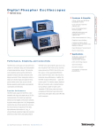
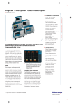
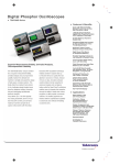
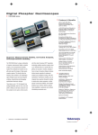
Digital Phosphor Oscilloscopes
TDS7000 Series
Features & Benefits
4 GHz, 1 GHz and 500 MHz
bandwidth models
Up to 20 GS/s real-time
capture rate
Up to 32 Megasamples
memory depth
>400,000 wfms/second
maximum waveform
capture rate
Jitter measurements to 1 psRMS
Graphical user interface
Control via classic direct
controls, touch-sensitive color
display or mouse
Open Windows® environment
Built in networking
Applications
Verification, debug and
characterization of
sophisticated designs
Performance, Simplicity, and Connectivity
TDS7000 Series oscilloscopes are high perform-
TDS7000 Series high bandwidth signal access
ance solutions for verification, debug, and charac-
solutions include the P7240 4 GHz (120 ps rise
terization of sophisticated electronic designs. The
time) active probe and the P7330 3 GHz (130 ps
family features exceptional signal acquisition per-
rise time) differential probe. Small form-factors and
formance, operational simplicity and open connec-
a wide array of tip accessories ensure effective-
tivity to the design environment. Classic analog-
ness. In addition, the TDS7404 includes the
style controls, a large touch-sensitive display and
TekConnect™ signal interconnect system. This
graphical menus provide intuitive control. Open
interface replaces traditional BNC input connectors
access to the Windows operating system enables
with a convenient positive-locking interface suitable
unprecedented customization and extensibility.
for higher system bandwidths. P7000 Series probes
are directly compatible with TekConnect signal
Superior Performance
TDS7000 models range from 500 MHz to 4 GHz
interconnect system along with adapters that
provide SMA, BNC and N connections.
bandwidth with single-shot sample rates to 20 GS/s,
meeting demands of the latest high speed logic
families and multi-Gigabit communication standards.
Acquisition memory options from 2 to 32 Megasamples
maximize the value of high sample rate and ensure
that critical events are captured with fine detail.
High performance jitter analysis to 1 psRMS is
achieved through exceptional trigger and acquisition
performance, deep memory and applied software.
1
Digital Phospor Oscilloscopes • TDS7000 Series • http://dpo.tektronix.com
Jitter and timing analysis
Spectral analysis
Disk drive analysis
Investigation of transient
phenomena
Digital Phosphor Oscilloscopes
TDS7000 Series
Figure 1. Digital Phosphor technology provides
unprecedented waveform capture rate, maxi
mizing the probability of discovering hidden
faults and revealing dynamic signal behavior.
Figure 2. Extensive use of illustrations helps
users locate advanced features quickly and
apply them with confidence.
Figure 3. Sophisticated analysis capabilities
allow users to fully characterize and document
design performance.
Digital Phosphor Oscilloscopes
form display area remains visible even when dis-
Application-specific Extensions
Signal observation time is critical for successful dis-
playing control windows so changes in the wave-
The TDS7000 family contains many extended fea-
covery of intermittent faults and characterization of
form aren’t missed when making selections or
tures to quantify and document signal characteris-
complex dynamic signals. TDS7000 Series Digital
adjustments. Context-sensitive help supplements
tics. These features remain close at hand without
Phosphor Oscilloscopes incorporate 3rd generation
graphic control windows and encourages users to
cluttering the human interface. Applied measure-
DPX technology to enable maximum waveform cap-
apply advanced capabilities to solve their problem.
ment extensions can be installed to enhance
ture rates of more than 400,000 waveforms per
TDS7000 capabilities. Optional applications include
second. This unprecedented performance allows
The adaptable TDS7000 Series human interface
jitter analysis and disk drive measurements. These
users to fully visualize signal activity. In trou-
readily supports any operating style and environ-
applications build on the precision signal acquisition
bleshooting applications, Digital Phosphor can save
ment. Users can select traditional instrument-style
performance of TDS7000 Series to address the
minutes, hours, or even days by quickly revealing
buttons for navigation or switch to a Windows menu
need for application specific measurements to
the nature of faults so sophisticated trigger modes
bar. Classic analog-style controls provide instant
quickly quantify device performance.
can be applied to isolate them.
access to the most frequently used functions while
the large touch sensitive display provides intuitive
Operational Simplicity
The TDS7000 Series graphical user interface delivers sophisticated capability to advanced users without intimidating occasional users. The front panel
includes a complete set of classic analog-style controls for most commonly used features. For
advanced use, the combination of large 10.4 inch
(264 mm) touch sensitive display and graphical
interface creates a highly visual environment with
explicit illustration of instrument features. The wave
menu operation. Waveform positions, cursor locations and trigger level can be directly dragged using
the touch screen or a mouse. A graphical drag-box
can be used to select a waveform area for zooming,
histogram analysis or measurement gating. The USB
interface allows a mouse, keyboard and other
peripherals to be added without powering off the
instrument. With this flexibility, TDS7000 Series
instruments readily adapt to a cart, cluttered bench
top, shelf, floor and other locations that otherwise
make operation awkward.
2
Digital Phospor Oscilloscopes • TDS7000 Series • http://dpo.tektronix.com
Intuitive Zooming
TDS7000 acquired waveforms are always horizontally fit into the display. This “big picture” is retained
for context while zoom is used to select areas of
specific interest. Waveform zoom can be directly
controlled with knobs or the graphical user interface
for intuitive interaction.
Digital Phosphor Oscilloscopes
TDS7000 Series
Enhanced Spectral Analysis
The TDS7000 Series includes a unique spectrumanalyzer style interface for performing frequency
domain analysis. Controls such as center frequency,
frequency span, resolution bandwidth and reference
level provide access to wide- or narrow-band frequency, phase, and group delay information. A gating function allows selection of only a portion of the
time-domain signal for analysis. These controls
Figure 4. Open access to the Windows desktop
allows users to leverage standard tools for
documentation, analysis, information browsing
and communications.
Parametric Measurements
allow users to focus on extracting spectral information instead of confronting the idiosyncrasies of
FFTs found in typical DSOs.
View the Windows® Desktop
on Separate Monitor
TDS7000 can also be expanded with the addition of
an external monitor. With dual-monitor mode
enabled the instrument retains live scope displays
while other applications such as publishing, analysis
or browsing tools reside on the external monitor.
Users can easily transfer images and waveform
data from TDS7000 to the locally running application or view Web-based reference information while
using the scope for design work.
Standard Interfaces
The TDS7000 includes standard interfaces for con-
Complete Connectivity
The TDS7000 includes a complete parametric meas-
The TDS7000 Series includes open access to the
urement system for signal characterization. Direct
Windows operating environment. While the
selection from a graphical palette makes locating
instrument remains a dedicated oscilloscope, the
choices simple. Users can quickly reassign measure-
ability to access the Windows desktop creates a
ments to a different waveform, simplifying verifica-
powerful new tool. Built-in applications such as
tion tasks. Split cursors make it easy to measure
WordPad, Paint and a web browser allow users to
trace-to-trace timing characteristics. Measurement
concurrently maintain lab notes while working with
statistics can be gathered for deeper insight.
the instrument. This saves time and eliminates
Measurement results are easily extracted for inclu-
error-prone steps associated with transporting
sion in a document or analysis in a spreadsheet
images for later report development. Other applica-
using the Windows clipboard or an Export function.
tions such as Microsoft Excel, MATLAB® and
trol and peripheral expansion. The GPIB command
set shares a high degree of commonality with previous TDS 500/700-class instruments while increasing hardware and software performance. Both USB
and PS-2 interfaces are included for mouse, keyboard and other peripheral expansion. USB offers
the advantage of hot-insertion and removal so
devices can be added or removed without cycling
power. The TDS7000 also includes a LAN interface
for network connection.
MathCAD® can be installed in the instrument to
Powerful Math
accomplish local signal analysis. The installation of
The TDS7000 Series allows user defined math
networking enables Web-based information brows-
expressions to be performed on waveform data giv-
ing, e-mail exchange, printing and file sharing.
ing them the opportunity to get on-screen results in
terms that they can define. Common waveform math
functions are provided at the touch of a button. For
advanced applications, algebraic expressions consisting of waveform sources, math functions, measurement values and scalars can be created easily
using a calculator-style editor. This allows users to
quickly transform raw waveform data into powerful
information that is readily interpreted.
Digital Phospor Oscilloscopes • TDS7000 Series • http://dpo.tektronix.com 3
Digital Phosphor Oscilloscopes
TDS7000 Series
Characteristics
Vertical System
TDS7054
Input Channels
Analog Bandwidth (–3 dB)
Calculated Rise Time 10 mV/div – 1 V/div
TDS7104
4
4
4
500 MHz
1 GHz
4 GHz
800 ps
400 ps
100 ps
Hardware Bandwidth Limits
250 MHz or 20 MHz
Input Coupling
Input Impedance
TDS7404
AC, DC, Gnd
DC, Gnd
1 MΩ ±0.5% or 50 Ω ±1%
50 Ω ±2.5%
Input Sensitivity, 1 MΩ
1 mV/div to 10 V/div
Input Sensitivity, 50 Ω
1 mV/div to 1 V/div
2 mV/div to 1 V/div
8-bits (>11-bits w/averaging)
8-bits (>11-bits w/averaging)
Vertical Resolution
Max Input Voltage, 1 MΩ
±150 V CAT I Derate at 20 dB/decade to
9 VRMS above 200 kHz
Max Input Voltage, 50 Ω
5 VRMS, with peaks less than ±30 Volts
Determined by TekConnect accessory
1.00%
1.00%
1 mV/div – 100 mV/div ±1 V
101 mV/div – 1 V/div ±10 V
1.01 V/div – 10 V/div ±100 V
2 mV – 50 mV/div ±0.5 V
50.5 mV – 99.5 mV ±0.25 V
100 mV – 500 mV ±5 V
505 mV – 1 V/div ±2.5 V
Channel to Channel Isolation
Any two channels at equal vertical
scale settings
≥100:1 at 100 MHz and ≥30:1 at the rated bandwidth
≥100:1 at 4 GHz
DC Measurement Accuracy
Stated for average >16 waveforms
±((0.3% * |Reading – Net Offset|) + Offset Accuracy +
(0.06 div * V/div))
Net Offset = Offset – (Position * Volts/div)
±((1.0% * |Reading – Net Offset|) + Offset Accuracy +
(0.06 div * V/div))
Net Offset = Offset – (Position * Volts/div)
Delta-DC Measurement Accuracy
Stated for average >16 waveforms
±((1.0% * |Reading|) + (0.1 div * V/div)+ 0.3 mV)
±((1.0% * |Reading|) + (0.1 div * V/div)+ 0.3 mV)
DC Gain Accuracy
Offset Range
Timebase System
TDS7054
Timebase Range
TDS7104
50 ps – 10 s/div
16 ns to 250 s
16 ns to 250 s
Timebase Delay Time Range
Channel to Channel Deskew Range
Time Interval Accuracy
±25 ns
±25 ns
±(0.30 sample interval) +
(15 ppm * reading)
±(0.15/sample rate) +
(10 ppm * reading)
Trigger Jitter (RMS)
Long Term Sample Rate and
Delay Time Accuracy
4
TDS7404
200 ps/div – 40 s/div
8 psRMS (typical)
7 psRMS
±15 ppm over ≥1 ms interval
±10 ppm over ≥1 ms interval
Digital Phospor Oscilloscopes • TDS7000 Series • http://dpo.tektronix.com
Digital Phosphor Oscilloscopes
TDS7000 Series
Acquisition System
TDS7054
TDS7104
TDS7404
1 channel (max)
5 GS/s
10 GS/s
20 GS/s
2 channels (max)
5 GS/s
5 GS/s
10 GS/s
Real-time Sample Rates
3-4 channels (max)
2.5 GS/s
2.5 GS/s
5 GS/s
Equivalent time sample rate (max)
250 GS/s
250 GS/s
250 GS/s
Maximum record length per channel
with standard memory
with Memory Opt. 1M
400 k (1 ch), 200 k (2 ch), 100 k (4 ch)
400 k (1 ch), 200 k (2 ch), 100 k (4 ch)
2 M (1 ch), 1 M (2 ch), 500 k (4 ch)
2 M (1 ch), 1 M (2 ch), 500 k (4 ch)
with Memory Opt. 2M
8 M (1 ch), 4 M (2 ch), 2 M (4 ch)
8 M (1 ch), 4 M (2 ch), 2 M (4 ch)
with Memory Opt. 3M
16 M (1 ch), 8 M (2 ch), 4 M (4 ch)
16 M (1 ch), 8 M (2 ch), 4 M (4 ch)
with Memory Opt. 4M
32 M (1 ch), 16 M (2 ch), 8 M (4 ch)
Maximum Duration at Highest Real-time Resolution (1 ch)
Time Resolution (single-shot)
TDS7054
TDS7104
TDS7404
50 ps (20 GS/s)
200 ps (5 GS/s)
100 ps (10 GS/s)
Max Duration with Standard Memory
80 µs
40 µs
20 µs
Max Duration with Opt. 1M
400 µs
200 µs
100 µs
Max Duration with Opt. 2M
1.6 ms
800 µs
400 µs
Max Duration with Opt. 3M
3.2 ms
1.6 ms
800 µs
Max Duration with Opt. 4M
1.6 ms
Digital Phospor Oscilloscopes • TDS7000 Series • http://dpo.tektronix.com 5
Digital Phosphor Oscilloscopes
TDS7000 Series
Acquisition Modes
TDS7054
FastAcq Acquisition
Maximum FastAcq Waveform Capture Rate
Sample
TDS7104
>200,000 wfms/sec
>200,000 wfms/sec
>400,000 wfms/sec
Acquire sampled values
Acquire sampled values
Acquire sampled values
Peak Detect
Minimum Peak Detect Pulse Width
TDS7404
FastAcq optimizes the instrument for analysis of dynamic signals and capture of infrequent events
Captures narrow glitches at all real-time sampling rates
≤1 ns
≤1 ns
Averaging
From 2 to 10,000 waveforms included in average
Envelope
From 2 to 2x10⁹ waveforms included in min-max envelope
Hi-res
400 ps
Real-time boxcar averaging reduces random noise and increases resolution
FastFrame Acquisition
Acquisition memory divided into segments; maximum trigger rate 150,000 waveforms per second.
Time of arrival recorded with each event
Trigger System
TDS7054
TDS7104
TDS7404
0.35 div DC to 50 MHz
increasing to 1 div at 500 MHz
0.35 div DC to 50 MHz
increasing to 1 div at 1 GHz
0.35 div DC to 50 MHz
increasing to 1 div at 3 GHz
400 mV from DC to 50 MHz
increasing to 750 mV at 100 MHz
250 mV from DC to 50 MHz
increasing to 500 mV at 100 MHz
250 mV from DC to 50 MHz
increasing to 350 mV at 500 MHz
Auto, Normal and Single
Auto, Normal and Single
Auto, Normal and Single
Sensitivity
Internal DC Coupled
External (Auxiliary Input)
Main Trigger Modes
Trigger Sequences
Main, Delayed by Time, Delayed by Events. All sequences can include separate
horizontal delay after the trigger event to position the acquisition window in time
Trigger Level Range
Internal
External (Auxiliary Input)
Line
Trigger Coupling
Trigger Holdoff Range
6
±12 divisions from
center of screen
±12 divisions from
center of screen
±12 divisions from
center of screen
±8 V
±8 V
±8 V
fixed at 0 V
fixed at 0 V
fixed at 0 V
DC, AC (attenuate <60 Hz), HF Rej (attenuate >30 kHz), LF Rej (attenuates <80 kHz), Noise Reject (reduce sensitivity)
250 ns minimum to 12
seconds maximum
Digital Phospor Oscilloscopes • TDS7000 Series • http://dpo.tektronix.com
250 ns minimum to 12
seconds maximum
250 ns minimum to 12
seconds maximum
Digital Phosphor Oscilloscopes
TDS7000 Series
Edge – Positive or negative slope on any channel or front
panel auxiliary input. Coupling includes DC, AC, noise
reject, HF reject and LF reject.
Pattern – Trigger when pattern goes false or stays true
for specified period of time. Pattern – (AND, OR, NAND,
NOR) specified for four input channels defined as HIGH,
LOW or Don’t Care.
Glitch – Trigger on or reject glitches of positive, negative,
or either polarity. Minimum glitch width is 1.0 ns with
200 ps resolution.
State – Any logical pattern of channels (1, 2, 3) clocked
by edge on channel 4. Trigger on rising or falling clock
edge.
Width – Trigger on width of positive or negative pulse
either within or out of selectable time limits (1 ns to 1 s).
Trigger Delay by Time – 16 ns to 250 seconds.
Calculus – Integrate, differentiate.
Trigger Delay by Events – 1 to 10,000,000 Events.
Frequency Domain Functions – Spectral magnitude and
phase, real and imaginary spectra.
Trigger Modes
Runt – Trigger on a pulse that crosses one threshold but
fails to cross a second threshold before crossing the first
again. Optional time qualification.
Timeout – Trigger on an event which remains high, low,
or either, for a specified time period, selectable from 1 ns
to 1 s with 200 ps resolution.
Transition – Trigger on pulse edge rates that are faster
or slower than specified. Slope may be positive, negative
or either.
Setup/Hold – Trigger on violations of both setup time and
hold time between clock and data present on any two
input channels.
Waveform Measurements
Amplitude – Amplitude, High, Low, Maximum, Minimum,
Peak to Peak, Mean, Cycle Mean, RMS, Cycle RMS,
Positive Overshoot, Negative Overshoot.
Time – Rise time, Fall time, Positive Width, Negative
Width, Positive Duty Cycle, Negative Duty Cycle, Period,
Frequency, Delay.
Waveform Processing/Math
Algebraic Expressions – Define extensive algebraic
expressions including waveforms, scalars and results of
parametric measurements e.g. (Integral (Ch1Mean(Ch1))*1.414.
Arithmetic – Add, subtract, multiply, divide waveforms and
scalars.
Vertical Units – Magnitude: Linear, dB, dBm; Phase:
degrees, radians.
Window Functions – Rectangular, Hamming, Hanning,
Kaiser-Bessel, Blackman-Harris, Gaussian, Flattop2, Tek
Exponential.
Combination – Area, Cycle Area, Phase, Burst Width.
Histogram-related – Waveform count, Hits in box, Peak
hits, Median, Maximum, Minimum, Peak to Peak, Mean
(µ), Standard Deviation (σ), µ+1 σ, µ+2 σ, µ+3 σ.
Digital Phospor Oscilloscopes • TDS7000 Series • http://dpo.tektronix.com 7
Digital Phosphor Oscilloscopes
TDS7000 Series
Display Characteristics
Input/Output Ports
Display Type – Liquid crystal active-matrix color display.
Probe Compensator Output – Front panel BNC connector, requires Probe Cal-Deskew Fixture (included) for probe
attachment. Amplitude 1 V±1.0% into a ≥50 Ω load, frequency 1 kHz ±5%.
Display Size – 211.2 mm (W) x 158.4 mm (H), 264 mm
(10.4 in) diagonal.
Display Resolution – 640 horizontal x 480 vertical
pixels.
Waveform Styles – Vectors, Dots, Intensified Samples,
Variable Persistence, Infinite Persistence.
Computer System and Peripherals
CPU – Intel® Celeron™ Processor, 500 MHz.
PC System Memory – 128 MB.
Hard Disk Drive – Rear-panel, removable hard disk drive,
>4.3 GB capacity.
Floppy Disk Drive – Front panel 3.5 in floppy disk drive,
1.44 MB capacity.
CD-ROM Drive – Rear panel CD-ROM drive.
Mouse – Logitech thumb wheel model included, USB
interface.
Keyboard – Order 119-6297-00 (USB interface).
8
Analog Signal Output Amplitude – Front-panel BNC
connector, provides a buffered version of the signal that
is attached to the Channel 3 input when Ch 3 is selected
as trigger source. 20 mV/div ±20% into a 1 MΩ load,
10 mV/div ±20% into a 50 Ω load.
Analog Signal Output Bandwidth, Typical –
TDS7054/TDS7104: 100 MHz into a 50 Ω load
TDS7404: 1 GHz into a 50 Ω load.
Auxiliary Output Levels – Front-panel BNC connector,
provides a TTL-compatible, polarity switchable pulse
when the oscilloscope trigger.
Parallel Port – IEEE 1284, DB-25 connector.
Audio Ports – Miniature phone jacks for stereo
microphone input and stereo line output.
USB Port – Allows connection or disconnection of USB
keyboard and/or mouse while oscilloscope power is on.
Digital Phospor Oscilloscopes • TDS 7000 Series • http://dpo.tektronix.com
Keyboard Port – PS-2 compatible.
Mouse Port – PS-2 compatible.
LAN Port – RJ-45 connector, supports 10Base-T and
100Base-T.
Serial Port – DB-9 COM1 port.
SVGA Video Port – DB-15 female connector; connect a
second monitor to use dual-monitor display mode.
Supports Basic requirements of PC99 specifications.
GPIB Port – IEEE 488.2 standard.
Scope VGA Video Port – DB-15 female connector,
31.6 kHz sync, EIA RS-343A compliant, connect to show
the oscilloscope display, including live waveforms on an
external monitor or projector.
Power Source
Power – 100 - 240 VRMS ±10%, 50/60 Hz; 115 VRMS
±10%, 400 Hz; CAT II, <300 W (450 VA).
Digital Phosphor Oscilloscopes
TDS7000 Series
Physical Characteristics
Benchtop Configuration
Dimensions
Height
Width
Depth
Weight
Net
Shipping
mm
277
455
425
kg
18
37
in.
10.9
17.9
16.75
lbs.
39
80
Altitude –
Operating: 10,000 ft. (3,048 m).
Mechanical
Cooling – Required clearances:
in.
Top
0 or >3
Bottom
0
Left side
3
Right side
3
Front
0
Rear
0
mm.
76
0
76
76
0
0
Environmental
Rackmount Configuration
Dimensions
Height
Width
Depth
Weight
Net
Kit
mm
277
502
486
kg
19
5.6
in.
10.5
19.75
19.125
lbs.
41
12.25
Temperature –
Operating: 0°C to +50°C, excluding floppy disk and CDROM drives; +10°C to +45°C, including floppy disk and
CD-ROM drives.
Nonoperating: 40,000 ft. (12,190 m).
Random Vibration –
Operating: 0.00015 g2/Hz from 5 to 350 Hz,
–3 dB/octave from 350 to 500 Hz, 0.000105 g2/Hz at
500 Hz. Overall level of 0.27 GRMS.
Nonoperating: 0.0175 g2/Hz from 5 to 100 Hz,
–3 dB/octave from 100 to 200 Hz, 0.00875 g2/Hz from
200 to 350 Hz, –3 dB/octave from 350 to 500 Hz,
0.006132 g2/Hz at 500 Hz. Overall level of 2.28 GRMS.
Safety – UL 3111-1, CSA-22.2 No. 1010.1,
EN61010-1.
Nonoperating: –22°C to +60°C.
Humidity –
Operating: 20% to 80% relative humidity with a
maximum wet bulb temperature of +29°C at or below
+50°C, noncondensing. Upper limit derated to 25%
relative humidity at +50°C.
Nonoperating: With no diskette in floppy disk drive. 5%
to 90% relative humidity with a maximum wet bulb temperature of +29°C at or below +60°C, noncondensing.
Upper limit derated to 20% relative humidity at +60°C.
Digital Phospor Oscilloscopes • TDS 7000 Series • http://dpo.tektronix.com 9
Digital Phosphor Oscilloscopes
TDS7000 Series
Ordering Information
TDS7054
500 MHz Digital Phosphor Oscilloscope.
TDS7104
1 GHz Digital Phosphor Oscilloscope.
TDS7404
Power Cord Options for all Models
Software
Opt. A1 – Universal European power cord (220 V, 50 Hz).
TDSJIT2 Jitter Analysis Software.
Opt. A2 – UK power cord (240 V, 50 Hz).
TDSDDM2 Disk Drive Analysis Software.
Opt. A3 – Australia power cord (240 V, 50 Hz).
Opt. A5 – Switzerland power cord (220 V, 50 Hz).
WSTRO Wavestar™ waveform capture and
documentation software.
Opt. A99 – No power cord.
Cables
Opt. AC – China power cord.
GPIB Cable (1 m) – Order 012-0991-01.
Recommended Accessories
GPIB Cable (2 m) – Order 012-0991-00.
Keyboard (USB interface) – Order 119-6297-00.
RS-232 Cable – Order 012-1298-00.
Service Manual – Order 071-0711-00.
Centronics Cable – Order 012-1250-00.
4 GHz Digital Phosphor Oscilloscope.
All models include: Accessory pouch, Front cover,
Mouse, Probe Calibration and Deskew Fixture
(067-0405-00), Quick Reference (020-2335-00), User
Reference (071-0700-00), GPIB Programmer’s
Reference, TDS 7000 Series Product Software CD-ROM,
TDS 7000 Series operating system restoration CD-ROM,
Performance verification procedure PDF file, NIST,
MIL-STD-45662A and ISO9000 Calibration Certificate,
Power Cord.
TDS7054 also includes: (4) P6139A 500 MHz, 10x
Passive Probes.
Transit Case – Order 016-1522-00.
TekConnect Adapters –
TCA-SMA TekConnect-to-SMA Adapter.
TCA-N TekConnect-to-N Adapter.
TCA-BNC TekConnect-to-BNC Adapter.
TDS7404 also includes: (4) TekConnect to SMA adapters
(TCA-SMA).
Instrument Acquisitions Memory Upgrades
Acquisition memory upgrades equivalent to Options 1M – 4M can be ordered to extend instrument performance after initial purchase. Users can install upgrades without opening the instrument case or requiring on-site service. Order the appropriate TDS7Mxx kit from the following table according to current and intended configuration.
To Opt. 1M
From Standard Memory
TDS7M01
From Opt. 1M
From Opt. 2M
From Opt. 3M
10 Digital Phospor Oscilloscopes • TDS 7000 Series • http://dpo.tektronix.com
To Opt. 2M
To Opt. 3M
To Opt. 4M (TDS7404 only)
TDS7M02
TDS7M03
TDS7M04
TDS7M12
TDS7M13
TDS7M14
TDS7M23
TDS7M24
TDS7M34
Digital Phosphor Oscilloscopes
TDS7000 Series
Instrument Options (Available where indicated by "x")
TDS7054
TDS7104
TDS7404
Acquisition Memory Options
1M
2 Msamples max, 500 ksamples/ch
x
x
x
2M
8 Msamples max, 2 Msamples/ch
x
x
x
3M
16 Msamples max, 4 Msamples/ch
x
x
x
4M
32 Msamples max, 8 Msamples/ch
x
Mounting Options
1K
K4000 Scope cart
x
x
x
1R
Rackmount kit
x
x
x
J1
TDSJIT2 Jitter Analysis Software
x
x
x
J2
TDSDDM2 Disk Drive Analysis Software
x
x
x
No Probes
x
x
x
Software Options
Probe Options
30
33
Add (1) P6158 3 GHz, 20x Low C Probe
34
Add (1) P6247 1.0 GHz Differential Probe
x
x
35
Add (1) P6243 1.0 GHz Active Probe
x
36
Add (1) P6139A 500 MHz, 10x Passive Probe
x
37
Add (1) P6245 1.5 GHz Active Probe
x
39
Add (1) P6248 1.7 GHz Differential Probe
x
51
Add (1)P7240 4 GHz Active Probe
x
52
Add (1) P7330 3 GHz Differential Probe
x
x
Service Options
D1
Calibration data report
x
x
x
C3
Additional 2 years of calibration
x
x
x
D3
Calibration data report for Option C3
x
x
x
R3
Additional 2 years of repair
x
x
x
Digital Phospor Oscilloscopes • TDS 7000 Series • http://dpo.tektronix.com 11
Digital Phosphor Oscilloscopes
TDS7000 Series
Contact Tektronix:
ASEAN Countries (65) 356-3900
Australia & New Zealand 61 (2) 9888-0100
Austria, Central Eastern Europe,
Greece, Turkey, Malta & Cyprus +43 2236 8092 0
Belgium +32 (2) 715 89 70
Brazil and South America 55 (11) 3741-8360
Canada 1 (800) 661-5625
Denmark +45 (44) 850 700
Finland +358 (9) 4783 400
France & North Africa +33 1 69 86 81 81
Germany +49 (221) 94 77 400
Hong Kong (852) 2585-6688
India (91) 80-2275577
Italy +39 (2) 25086 501
Japan (Sony/Tektronix Corporation) 81 (3) 3448-3111
Mexico, Central America, & Caribbean 52 (5) 666-6333
The Netherlands +31 23 56 95555
Norway +47 22 07 07 00
People’s Republic of China 86 (10) 6235 1230
Republic of Korea 82 (2) 528-5299
South Africa (27 11) 651-5222
Spain & Portugal +34 91 372 6000
Sweden +46 8 477 65 00
Switzerland +41 (41) 729 36 40
Taiwan 886 (2) 2722-9622
United Kingdom & Eire +44 (0)1344 392000
USA 1 (800) 426-2200
For other areas, contact: Tektronix, Inc.
Export Sales, P.O. Box 500, M/S 50-255,
Beaverton, Oregon 97077-0001, USA 1 (503) 627-6877
For the most up-to-date product information
visit our web site at www.tektronix.com
For Further Information
Tektronix maintains a comprehensive, constantly expanding collection of
application notes, technical briefs and other resources to help engineers
working on the cutting edge of technology.
Please visit “Resources For You” on our Web site at www.tektronix.com
Copyright © 2000, Tektronix, Inc. All rights reserved. Tektronix products are
covered by U.S. and foreign patents, issued and pending. Information in this publication supersedes that in all previously published material. Specification and price
change privileges reserved. TEKTRONIX and TEK are registered trademarks of
Tektronix, Inc. All other trade names referenced are the service marks, trademarks
or registered trademarks of their respective companies.
4/00
12 Digital Phospor Oscilloscopes • TDS 7000 Series • http://dpo.tektronix.com
HB/PG
55W-13766-0