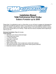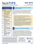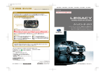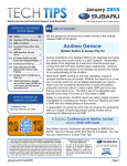
1
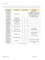
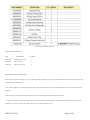
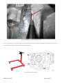
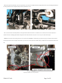
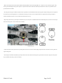
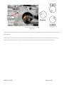
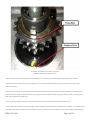
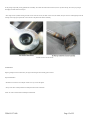
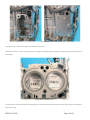
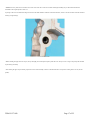
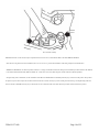
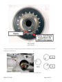
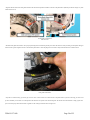
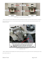
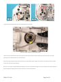
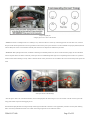
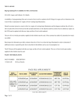
TSB 02-157-14R
Surface Treatment Change To Oil Control Piston Rings
2013-2014 Subaru Legacy and Outback Models with 2.5L FB Engine
2011-2014 Subaru Forester Models with 2.5L FB Engines
2012-2013 Subaru Impreza and 2013MY XV Crosstrek Models with 2.0L FB Engine
Information regarding a major change to the repair procedures previously outlined in Service Bulletins 02-143-13R, 02-144-13R and 02-145-13R. These bulletins
provided a repair procedure for the replacement of the piston rings to address verified concerns of unusual engine oil consumption.
Vehicles confirmed as having this condition which are within the supplied VIN ranges will no longer be repaired with piston ring replacement.
The revised repair procedure to address verified unusual oil consumption concerns on these specific vehicles will consist of replacing the engine short block assembly.
It is critical to understand the nature of the concern as reported by the customer and to confirm the actual condition prior to attempting repairs. Some oil consumption
can and should be expected as a by-product of engine operation even where no concern exists.
Failure to recognize this and correctly diagnose the condition presented can result in unnecessary repairs.
For example: a vehicle which is presented with a report of a low engine oil level (as read on engine dipstick/ gauge or indicated by illumination of the low engine oil
level warning lamp), which is at or near the time / mileage of the next service interval (based upon the date / mileage of the most recent oil change), is not representative
of unusual oil consumption.
The information supplied in this bulletin is only applicable to vehicles within the specific production ranges of this publication exhibiting the condition(s) previously
described.
IMPORTANT: Read and understand this bulletin COMPLETELY before starting an oil consumption test or initiating any repairs.
Concerns related to a possible oil consumption condition are generally initiated when the customer believes the engine oil level on the dipstick has dropped since the
last time it was checked or when the low oil lamp illuminates. These types of complaints by themselves do not directly indicate a concern with the vehicle exists.
It is important to understand all the factors involved in order to make a sound decision regarding whether or not a repair is required or if an oil consumption test should
even be started.
When speaking with customers about a reported or suspected oil consumption concern, always keep the following in mind:
Some engine oil will always be consumed as part of normal engine operation. How much and when it is consumed varies according to manufacturing tolerances, wear,
and vehicle usage patterns.
TSB 02-157-14R
Page 1 of 25
With the extended service intervals commonly used for today’s engines combined with one or more of the conditions listed below, typical engine oil consumption may
require adding engine oil in between scheduled maintenance intervals:
• When the engine is new and within the break-in period (during the first 1000 miles of operation)
• When the engine oil being used is of lower quality (other than “Energy or Resource Conserving” API
Engine Oil
Classification SM or SN or ILSAC, look for the starburst design with GF-4 or GF-5)
• When the incorrect oil viscosity is used (viscosity other than 0W-20 in the case of these specific vehicles)
• When engine braking is employed (use of the transmission’s gear ranges to decelerate while using the engine to apply resistance)
• When the engine is operated at high engine speeds (continually or under frequent, hard acceleration)
• When the engine is operated under heavy loads (frequent carrying of heavy cargo, passengers or trailer towing)
• When the engine idles for long periods of time (may be related to frequent use of a remote engine start system)
• When the vehicle is operated in stop and go and/or heavy traffic situations
• When the vehicle is used under severe temperature conditions (cold or hot)
• When the vehicle accelerates and decelerates frequently
TSB 02-157-14R
Page 2 of 25
Under these or similar operating conditions, the oil level should be checked more frequently. The engine oil and filter may also need to be changed more often. As per
the Owner’s Manual, engine oil consumption under these conditions may be as high as 1 quart per 1200 miles.
As related information, the low oil level warning light (on models so equipped) is designed to illuminate when the engine oil level in the sump drops below
approximately 4 quarts with the engine not running (engine is 1.1 quarts low on oil) and 2.4 quarts when the engine is running.
While this may seem very low, keep in mind that oil remains suspended in the engine while running and will not fully drain back until the engine has been shut off for
at least 5 minutes. In some rare cases, this light may illuminate with more oil present when the engine is running due to specific road or driving conditions such as
repeated hard acceleration/ deceleration, tight turning, driving on undulating roads.
In these cases, the light will generally reset on its own once the actual level is determined to be above the illumination threshold.
However, this may take some time as certain driving parameters must be met for the system to self-correct. As long as the oil level has been checked and adjusted (if
necessary), the immediate concern has been addressed.
If the lamp does not extinguish on its own after some time and the oil level remains full, an inspection of the circuit and components should be performed.
See Section 3 of the Owner’s Manual for more information on the oil level warning system. See Service Procedure to reduce false illumination of low oil level
warning lamp (on models so equipped) later in this bulletin for instructions on how to address customer concerns where the low engine oil level warning lamp
illuminates when the engine oil level is either full or nearly full.
The updated piston rings were incorporated into production as per the table below.
MODEL
STARTING VIN
DATE
2013-2014
Legacy and Outback
2013 Impreza 2.0L
n/a
D*025244
n/a
2/20/2013
2013 XV Crosstrek
D*855330
2011-2013 Forester
n/a
n/a
2014 Forester
n/a
n/a
TSB 02-157-14R
2/20/2013
Page 3 of 25
PART INFORMATION
The chart below provides a required part list for the short block replacement procedure. This list is provided as a reference only and may not be totally complete
depending on the needs of your specific repair. Always verify with your Parts Department that all needed parts with the most up-to-date part numbers are ordered.
part list for the short block replacement
TSB 02-157-14R
Page 4 of 25
part list for the short block replacement
MISCELLANEOUS MATERIALS
PART
DESCRIPTION
QUANTITY
SOA635065
ThreeBond 1280B / 1217G
1
SOA635041
Super Coolant, (qt.)
8
SOA635045
Engine Oil (qt.) 0W-20
6
SERVICE PROCEDURE / INFORMATION
Before starting any repairs, the first step is to always confirm the customer’s complaint. It is critical to get as much information from the customer as possible to help
you make the most accurate diagnosis.
• Review all the available service and repair history along with any other records the customer can provide to establish whether or not the vehicle has been properly
maintained.
• Perform a thorough visual inspection to make sure there are no external oil leaks that could be contributing to the condition.
• It is also very important to not overlook the engine’s PCV system and to confirm it is operating properly. Check the air filter assembly and throttle body / intake
manifold for any excessive oil residue which could be an indicator of a sticking or failed PCV valve.
TSB 02-157-14R
Page 5 of 25
NOTES:
• An oil consumption test will need to be completed to determine the proper course of action. There is a specific procedure and Oil Consumption Test form which must
be completed. See Subarunet \ Service \ Forms for the latest test form. Always print the latest form anytime a new test is started.
• Where applicable, available reprogramming to reduce the possibility of false low engine oil level warning lamp illumination must be installed. See Service Procedure
to reduce false illumination of low oil level warning lamp (on models so equipped) later in this bulletin for further instructions. This must be completed at either the
start or end of the consumption testing regardless of the final outcome.
IMPORTANT: At the start of the Oil Consumption Test Form, specific information regarding what prompted (reason for) the testing must be collected. Once this
questionnaire section of the form is completed, it must be faxed to 856-488-3199.
Upon completion of the actual consumption test, the remainder of the form must be completed and faxed AGAIN to 856-488-3199. This information is being collected
for quality assurance purposes only. You will not receive any response from these submissions.
This is NOT an authorization process. Proceed with any necessary testing or repairs as indicated by the information provided in this service bulletin, the Oil
Consumption Test form results, Subaru’s Claims Policies and Procedures, and your evaluation of the actual condition presented based upon your review of all three
areas.
Keep in mind, these repairs should only be completed when unusual oil consumption has been confirmed.
Before initiating the consumption test, all basic checks must be completed. These include (but are not limited to): confirming the actual oil level, noting if any oil has
been added prior to this visit and how much, checking for any external leaks, confirming PCV operation, and verifying that a consumption test has not already been
started or completed previously.
Always use the latest Oil Consumption Test form form found on Subarunet in the Service Forms area. Follow the instructions outlined on the form.
NOTE: The oil and filter change is only necessary if no prior consumption test has been completed or is already in process. There is no need for duplicate or repeat
testing.
One-time documented results are all that is required to move forward with these repairs.
Always close the repair order on the day the oil change has been completed and submit the claim for the oil consumption test using the coding provided at the end of
this bulletin. Indicate “Oil Consumption Test” in the comments field / box when entering your claim.
DO NOT hold the repair order open until the vehicle returns. Have the customer drive the vehicle then return for inspection when any of the following have occurred:
• At least 1200 miles have elapsed
• When the low engine oil level warning lamp illuminates (when equipped)
TSB 02-157-14R
Page 6 of 25
• When the oil level reaches the lower hole in the dipstick/ gauge (as determined by the customer).
The customer should be advised to not add oil unless there will be a significant delay before they can return for inspection once a low oil condition occurs. A one-time
check of the oil consumption by the retailer is all that is needed to establish if the condition outlined in this bulletin applies.
SPECIFIC SERVICE PROCEDURES
The following information is provided to underscore service procedures specific to the repairs outlined in this bulletin. They are not meant to represent the entire repair
process from start to finish.
The procedures provided here are specific to certain steps in the overall process. In some cases, they will differ greatly from the Service Manual instructions and should
be followed in place of the Service Manual for these specific areas only.
For the balance of the repair procedure, refer to the Service Manual. It is highly recommended to review all of the Service Manual procedures for short block
replacement then review these specific procedures to become familiar with the differences.
• When draining the engine oil, do not remove the engine oil filter. Leave the existing oil filter in place through engine disassembly, reassembly, installation and initial
startup after engine reassembly.
• When removing the engine, there is no need to remove the transmission case cover (CVT only) or to disconnect / disturb any of the transmission harness connectors.
While raising the transmission with the service jack placed under the front differential as shown in the illustration below, only raise it enough to access and remove the
engine mounting hardware.
Raising it too high can push the transmission up into the bulkhead / transmission tunnel and possibly cause damage.
TSB 02-157-14R
Page 7 of 25
raising the transmission with the service jack
• When removing the CVT fluid cooler (if equipped), leave it attached to its mounting bracket and remove as an assembly (3 bolts) from the transmission. Disconnect
just the engine coolant hoses from it and do not disturb the 2 short CVT fluid lines. Hook one of the cooler’s mounting bracket “ears” behind the bulkhead harness as
shown in the photo below to keep the cooler assembly out of your way. Use a shop cloth between the “ear” and the bulkhead harness to prevent any chafing.
TSB 02-157-14R
Page 8 of 25
keep the cooler assembly out of your way
• To make separating the transmission (CVT) from the engine easier, there is a pry relief shown below in the machined mounting surface of the transmission case near
the engine number. Use caution when applying any prying pressure and avoid twisting the tool to prevent case damage.
TSB 02-157-14R
Page 9 of 25
separating the transmission (CVT) from the engine pry relief
• Once the engine is removed, if you are using a generic engine stand (preferable since engine rotation is necessary), use the four mounting holes on the engine block
shown below to mount it. NOTE: Do not use the mounting studs in the upper oil pan.
four mounting holes on the engine block
TSB 02-157-14R
Page 10 of 25
• When removing the intake manifold, as shown in the photos below, leave the TGV assemblies attached to the upper intake, remove the 2 nuts holding the EGR tube to
the water pipe then remove the complete assembly from the cylinder heads as a unit.
EGR tube
• There is no need to remove the oil dipstick tube or the original oil filter from the front chain cover. While the cover is removed, store it face (front side) down to
minimize the chances of damaging the machined sealing surface on the block / head side. Also, don’t use it as a tray to store other removed parts.
• IMPORTANT: After all 32 bolts securing the chain cover are removed, be EXTREMELY careful where you pry and what you pry on to break the silicone sealant’s
bond. The photos below show an example of where NOT to pry. In this case, the cam cap became cracked requiring a complete cam carrier replacement. Patience is the
key!
cam cap became cracked
requiring a complete cam carrier replacement
TSB 02-157-14R
Page 11 of 25
• Refer to the instructions found in the Technician Reference Booklet (TRB) for Technical Training Module 105: “Chain Driven Valve Train Boxer Engines” when
removing and reassembling the timing chain components. The photos and instructions found in the TRB and provided below have shown to be preferable to those
provided in the Service Manual.
• The timing chains driving the camshafts are identical and are provided with colored identification links used to align with component timing marks. Chain guides are
also identical for the left and right banks. It is recommended to mark the parts as they are removed. Return them to their original positions during reassembly to
maintain established wear patterns. Colors used for the identification links will vary.
• Begin timing chain removal by positioning the crankshaft keyway at the 6:00 position. The RIGHT bank intake camshaft timing mark (Δ) must be at 6:00 with right
bank exhaust timing mark at 12:00 (camshafts will be unloaded).
Identification Link
• Compress the chain tensioner by hand, insert a pin through the lever into the access hole to lock the plunger in place then remove the 2 bolts, tensioner, guides and
right side timing chain.
• After turning the crankshaft CLOCKWISE, repeat the procedure for the LEFT side with the timing marks (Δ) positioned as shown below. Align the crank sprocket
keyway with RH chain dowel pin (shown in red below).
TSB 02-157-14R
Page 12 of 25
Align the crank sprocket keyway with RH
chain dowel pin
• Compress the chain tensioner by hand, insert a pin through the lever into the access hole to lock the plunger in place then remove the 2 bolts, tensioner, guides and the
left side timing chain.
• After the left chain is removed, turn the crankshaft in a COUNTER CLOCKWISE direction until the timing mark on the crankshaft sprocket (NOT the keyway) is
back to the 6:00 position as shown below. This positions all the pistons away from TDC and prevents accidental contact between the pistons and valves.
TSB 02-157-14R
Page 13 of 25
This positions all the pistons away from TDC and prevents
accidental contact between the pistons and valves
• Before proceeding, it is best to rotate the engine on the stand 90 degrees so it is vertical with one cylinder head facing up (head gasket surface horizontal).
• Remove the rocker cover then the cam carrier from the head that is “up”. Do not disturb the small camshaft end cap covers. Remove the cam carrier with the
camshafts as an assembly.
At this point, the rest of the valve train is sitting loose on the cylinder head. It is imperative all the rockers, selective lash caps and rocker pivots are returned to their
original positions on the cylinder head during reassembly. TIP: An egg carton for each head makes a perfect organizer tray. Make sure to mark it as necessary (front,
intake, exhaust) to eliminate any mixing of parts.
• Loosen the cylinder head bolts in proper order, remove the head, then flip the engine over and repeat the same steps for the opposite side.
• It is very important to take the time necessary to thoroughly clean the old silicone sealer from all the removed components before reassembly. It is a good idea to clean
the surrounding areas then use tape to block off any oil passages in the front cover and cam carriers so any small bits of removed silicone debris are kept from entering
TSB 02-157-14R
Page 14 of 25
the oil passages and possibly causing problems after reassembly. Once all the old sealer has been removed, remove any block-off tape, rinse out any oil passages
thoroughly with brake cleaner and shop air.
• Don’t forget to clean (without removing) the filter screens in the cam carriers (one filter in each carrier). In addition, always be sure to do a thorough inspection and
cleaning of the oil pan, pick-up tube and screen as shown in the photos below before reassembly.
the filter screens in the cam carriers
REASSEMBLY
Begin by putting the new short block onto your engine stand using the same mounting points as before.
Important Reminders:
• Install the new one-time use PCV adapter. NOTE: Never try to reuse the original.
• Swap over the PCV assembly and the PCV baffle plate onto the front of the block.
NOTE: No sealer is used between the baffle plate and the block.
TSB 02-157-14R
Page 15 of 25
PCV baffle plate
• If equipped, swap over the lower water jacket coolant baffles into the new block.
• Head gaskets are marked “L” and “R”. Always make sure they are properly installed while paying close attention to the sealer application areas as outlined in the
Service Manual.
Head gaskets are marked “L” and “R”.
• Always make sure to clean the head bolt threads and apply engine oil to the threads and head bolt washers before starting the torque sequence. Always follow the
torque sequence closely.
TSB 02-157-14R
Page 16 of 25
• IMPORTANT: If by chance the AVCS filter screens in the cam carriers have come loose or fallen out during disassembly, they are directional and MUST be
reinstalled in their original position. There is an
oil passage in the cam case which MUST align with a hole on the outside diameter of the filter screen tube otherwise, oil flow to the AVCS will be restricted or blocked
resulting in engine damage.
AVCS filter screen
• Before installing the upper and lower oil pans, always thoroughly clean and inspect the pick-up tube and screen. Always use new o-rings on the pick-up tube and both
oil pans during reassembly.
• After cleaning the upper oil pan assembly, replace the oil level switch assembly as shown in the illustration below. Torque the 2 retaining bolts to 6.4 Nm (56 inchpounds).
TSB 02-157-14R
Page 17 of 25
oil level switch assembly
IMPORTANT NOTE: At this time, this step for replacement of the oil level sensor is NOT APPLICABLE to 2012MY IMPREZA MODELS.
• Once the basic “long block” has been reassembled (valve cover to valve cover), proceed with installation of the timing components as outlined below.
• IMPORTANT REMINDER: To eliminate possible confusion, it is strongly recommended to follow the timing chain reinstallation procedure outlined in this TSB and
/ or the Technician Reference Booklet (TRB) for Module 105: “Chain Driven Valve Train Boxer Engines” instead of the Service Manual procedure.
• To begin timing chain re-installation, turn the crankshaft COUNTER-CLOCKWISE until the crankshaft sprocket keyway is back to the 6:00 position. This positions
the pistons away from TDC and prevents accidental contact with the valves. NOTE: The keyway is NOT a timing mark. The oblong / oval-shaped timing mark must
face front and be to the RIGHT of the keyway as shown below. Do not confuse this mark with a mark which may be found on the back side of the sprocket.
TSB 02-157-14R
Page 18 of 25
Oblong / Oval-Shaped
Timing Mark to the
RIGHT of the keyway
• Arrange the timing marks as shown below, turning the crankshaft CLOCKWISE into position. Align the indicator link with the timing mark on the crankshaft
sprocket, keyway with the dowel pin.
indicator link with the timing mark on the crankshaft sprocket
TSB 02-157-14R
Page 19 of 25
• Align the indicator links to the timing marks found on the outside of the sprocket assemblies as shown in the photos below (Exhaust sprocket face images vary with /
without exhaust VVT).
Timing Marks Aligned With
Indicator Links
• Install the chain guides and tensioner. Once proper positioning has been confirmed, pull the pin to release the tensioner. With your hand, grab and squeeze the upper
and lower chain / guides together as shown in the reference photo below to allow the plunger in the tensioner to fully extend and click into its furthest notch.
chain guides and tensioner
• If you have 3 notches showing, you want to get one more “click” so that 4 notches are visible as shown in the photos below. If you have 4 showing, you want to end
up with 5. Whether you start with 3 or 4 will depend on the amount of wear present on the chains and guides. The number of clicks listed here is simply a guide. The
point is to ensure proper initial chain tension is applied to avoid creating a brief rattle sound at engine start.
TSB 02-157-14R
Page 20 of 25
tension is applied to avoid creating a brief rattle sound at engine start
• If necessary, insert a plastic screwdriver handle between the lip of the block and the left side (B2) guide. Then, VERY CAREFULLY push down on the guide just
enough to get the extra tensioner notch / “click”. When using this method, always make sure you are using plastic on plastic and NOT metal on plastic to avoid
damaging the chain guides.
push down on the guide just enough to get the extra
tensioner notch / “click”
• Rotate the crankshaft COUNTER-CLOCKWISE until the crankshaft sprocket timing mark is at the 6:00 position. Position the cam sprocket timing marks as shown
below; intake 6:00, exhaust 12:00.
TSB 02-157-14R
Page 21 of 25
crankshaft sprocket timing mark
• Align the indicator link with the timing mark on the crankshaft sprocket as shown below.
indicator link with the timing mark on the crankshaft sprocket
• Same as the left side, align the indicator links to the timing marks found on the cam sprocket assemblies. Install the chain guides and tensioner. Once proper
positioning has been confirmed, pull the pin to release the tensioner.
With your hand, grab and squeeze the upper and lower left side chain / guides together to allow the plunger in the tensioner to extend fully and click into its furthest
notch as shown in the previous (right side) photo.
If necessary, insert a rubber-coated plier handle between the ledge area on the front of the block and the right side (B1) lower chain guide. Then, VERY CAREFULLY
lift up on the guide just enough to get the extra “click” on the tensioner as shown in the photo below.
TSB 02-157-14R
Page 22 of 25
lift up on the guide just
enough to get the extra “click” on the tensioner
• IMPORTANT: When re-installing the front cover assembly, be very careful to not allow it to contact any of the timing sprockets. If contact does occur, it will most
likely be with the exhaust sprockets and it is almost a guarantee the silicone sealer you have put on the front cover will be disturbed. If not properly addressed, that area
will most likely be the source of an oil leak after reassembly. Don’t hesitate to use a helper for the installation to prevent this.
• REMINDER: When replacing the short block, in addition to transferring the crankshaft position sensor, be sure to index the reluctor properly onto the crankshaft as
shown in the photos below. The reluctor is indexed by a dowel pin in the rear crankshaft flange which aligns with a corresponding hole in the reluctor. It is possible to
install the reluctor without indexing it correctly. Failure to index the reluctor correctly will result in a no-start condition due to an out of time crank position signal to the
ECM.
dowel pin in the rear crankshaft flange
• Once the engine is back in the car and filled with fluids, remove the fuel pump fuse and crank the engine over (for no more than 10 seconds at a time) to prime the
oiling system until the oil pressure warning light goes out.
Re-install the fuel pump fuse then run the engine initially with the original oil filter left on the front cover for approximately 5 minutes to catch any other remaining
debris. Check for any fluid leaks then install a new oil filter. Start the engine again and run it for another few minutes.
TSB 02-157-14R
Page 23 of 25
Shut off the engine and allow it cool down for at least five minutes. Re-check and top off the engine oil to the full mark on the dipstick before releasing the vehicle.
• Be advised, some higher than expected oil consumption may occur initially following the shortblock replacement until the new piston rings become seated. While
higher than expected normally, this oil consumption rate should not be as severe as verified prior to the repair. This will generally improve within 1000 miles of driving
until the expected oil consumption rate is achieved.
• Complete the following procedure (where applicable) to conclude the repair procedure, even if no complaint of this condition has been indicated by the customer.
SERVICE PROCEDURE TO REDUCE FALSE ILLUMINATION OF THE LOW OIL LEVEL WARNING LAMP (ON MODELS SO EQUIPPED)
Any repairs performed as part of this bulletin MUST include installation of the applicable ECM reprogramming file for Oil Level Detection and replacement of the oil
level switch. Refer to the applicable TSBs as listed below:
• 11-145-14R for 2013-2014MY Legacy and Outback models
• 11-148-14R for 2014MY Forester models
• 11-149-14R for 2013-14MY Impreza 2.0L and XV Crosstrek models
• 11-150-14 NEW TSB for 2012MY only Impreza models (reprogramming only)
VERY IMPORTANT: If a vehicle is presented where no repairs for actual oil consumption are required but an oil consumption test was completed, BOTH the
applicable ECM reprogramming file for Oil Level Detection AND the updated oil level switch (where applicable per the TSBs listed above) MUST be installed before
releasing the vehicle to the customer.
NOTES:
SOA now highly recommends connecting the Midtronics GR8 Diagnostic Battery Charger to the vehicle and utilizing the Power Supply Mode feature anytime a vehicle
control module is being reprogrammed. Once the GR8 is connected to the vehicle, as long as the battery is fully charged, it takes less than 3 minutes to boot-up the
charger, select the Power Supply Mode, and have the battery voltage stabilized and ready for reprogramming.
VERY IMPORTANT: This information is applicable to the Midtronics GR8 Diagnostic Battery Charger ONLY. It does not apply to any other brand / type of “generic”
battery charger whatsoever. ONLY the GR8 and its Power Supply Mode feature has been tested and approved by Subaru of America, Inc. (SOA).
If the GR8 indicates the vehicle’s battery must be charged, charge the battery using the GR8 before proceeding to reprogram the vehicle while using the Power Supply
Mode.
• Control module failures as a result of battery discharge during reprogramming are not a matter for warranty. Should any DTCs reset after the reprogramming update is
performed, diagnose per the procedure outlined in the applicable Service Manual.
TSB 02-157-14R
Page 24 of 25
An Approved j2534 Device can be used to reprogram the PCM
Subaru reprogramming files using a generic (non-OEM) SAE J2534 pass-thru vehicle programming device are available by contacting Service Technical Information
Company toll free at 1-866-428-2278.
The cost for the CD-ROM with all reprogramming files is $75.00 plus S/H and applicable state tax. Files will be updated four (4) times per year, in CD-ROM format,
with all available reprogramming service information at the same above offered cost. Authorized Subaru Dealers are provided the same reprogramming information.
02-157-14R
TSB 02-157-14R
Page 25 of 25