1
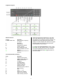
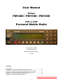
User Manual
Philips
FM1200 / FM1100 / FM1300
VHF or UHF
Personal Mobile Radio
Dennis Koller PA4DEN
Jan Buiting PE1CSI
Philips Mobile Radio Collection
July 2001
Contents
User Manual ............................................................................................. 1-6
Appendix A, The FM1200 SB0 PMR with Handsfree Kit................................ 7
Appendix B, FM1200/1300 Equipment Identification Code System................. 8
Appendix C, Microphone Socket and Power Connector Pinouts..................... 9
Appendix D, Local and Remote Mounting Options ........................................ 10
Appendix E, Frequently Asked Questions ................................................... 11
[This document to be printed in colour only]
-1-
Keyboard Layout:
Main Functions:
Key(s):
0123456789
*
#
E
F
G
H
When the transceiver is switched on, the upper
line of the display shows the current channel or
the frequency. If a valid tone code is received, it is
displayed in the lower right hand corner of the
display. The lower display line shows an S (signal
strength) meter in the form of a horizontal bar.
This is called the normal state.
Function:
Enter channel, frequency
or number
Scanning
Reverse shift
Activate tone squelch
(CTSS / 5-tone)
Go to Calling Channel
Switch between VFO and
Memory
Select second function of
next key
To activate the second function of a key, press
the H key. The text ‘Select Function'’ will appear.
The second (alternate) function of the next key
pressed is activated. Press H again to return to
the normal state.
Second (alternate) function:
Key:
1
2
3
4
5
6
8
*
0
#
E
F
G
Function:
Adjust transmit power
Adjust squelch trip level
Select CTCSS tone
To MENU
To Status Menu
Show names with
memory channels
Select step size
Exclude memory channel
from scanning
Call
Shift + / – / off
Select tone squelch
Clear Priority Channel
Clear memory Channel
-2-
1. Select Frequency
transmit a ZVEI 5-tone sequence at the start of
every transmission.
The transceiver operates in one of three modes.
Using the G button you may select between VCO
and Memory mode. The third mode is the
Priority Channel which may be switched on and
off with the F key.
Activate:
The tone squelch is activated by pressing the E
key. When receiving, the yellow LED lights. When
transmitting, the symbol 'T' appears behind the
frequency.
VCO mode
In VCO mode any frequency that complies with
the selected step size (4) may be entered using
the number keys on the keypad. The transceiver
automatically rounds off the frequency to a valid
entry. For example, of you want to listen at
435.012.500 MHz, at a step size of 12.5 kHz, all
you need to do is enter ‘501’:
435.---.--- →
435.0--.--- →
Adjust:
The code may be set as follows:
- Press H
- Press E
Now set the tone for the squelch. The tone code
has to be entered using the number keys. If a
number flashes, this indicates a DTMF tone.
435.012.500
If a step size of 25kHz is used, entering '501' will
cause the transceiver to round off to 435.000.000.
- Press H
Memory mode
Starting from VCO mode up to 100 preset
frequencies per bank may be stored in memory,
see Heading 5. These frequencies may be
selected when in Memory mode while it is also
possible to assign names to channel frequencies.
If no frequency has been assigned to the selected
channel the transceiver produces an error beep
and ignores the number entered.
( TX:
)
Now set the tone to be transmitted.
1750 Hz tone burst
A tone burst is transmitted by pressing the PTT
and Squelch Defeat buttons at the same time.
The frequency of the tone burst may be adjusted
in the Audio menu.
4. Select Step Size
Priority Channel mode
Provided a frequency has been assigned to the
Priority Channel (see Heading 6), this feature
allows you to change to this frequency at the flick
of a switch. The Calling Channel may be instantly
selected by pressing the F key.
- Press H
- Press 8
Display:
( Select Function )
( Step size: ** )
The desired step size is selected by pressing the
0 and # keys (← or →). Confirm your selection by
pressing any other key.
2. Select CTCSS tone
It may be undesirable for every transmission to be
heard on a certain frequency. A system called
CTCSS is therefore used to pass only those
transmissions containing a sub-audible tone of a
specific frequency. In the receiver a CTCSS
decoder is used to open the squelch and make
the transmission (speech) audible when a valid
CTCSS tone is detected.
The frequency of the CTCSS tone may be
selected as follows:
- Press H
- Press 3
Display:
( Select Function )
( RX:
)
5. Store favourite channels
Up to 100 favourite channels per bank may be
pre-set in the transceiver. A channel is stored as
follows:
Display:
- Select VCO mode
(43*.***.*** )
- Enter the desired frequency and choose
SHIFT and/or CTCSS if required
- Press H
(Select Function )
- Press G
(Store in: xx)
- Select a number, if number has an arrow
in front of it, it has been taken for another
frequency. This is replaced.
(Store in: xx)
- Press H
- If desired, give the channel a name.
(Name:
)
See Heading 10 for text entry.
- Press H again
Display:
( Select Function )
( TX CT:
**)
The lowest frequency is 67.0 Hz, the highest,
250.3 Hz. The quasi-value 'None' is available to
disable CTCSS. Separate CTCSS frequencies
may be used for TX and RX
3. Tone squelch
The squelch may be remain closed until a valid
ZVEI 5-tone code is received. It is also possible to
-3-
See Heading 7 for the name display on/off
function.
number key '2'. The desired letter or character is
selected by repeatedly pressing a number key.
The B button is used to delete a character. Text
beyond the cursor position will shift back, just as
with the DEL key when using a word processor.
The E button is used to enter a space.
All characters behind the keys on the keypad are
shown in the table below. The up and down arrow
keys C and D may be used to step through a
character group. The cursor may be moved by
pressing the left and right arrow keys F and G.
6. Storing Priority (PR) Channel
It is very useful, particularly in mobiles, to have a
single button available to retrieve the Priority
Channel. The Priority Channel frequency may be
programmed as follows:
Display:
- Select VCO mode
(43*.***.*** )
- Enter the desired frequency and set
SHIFT and/or CTCSS if required
- Press H.
( Select Function )
- Press F.
( Calling Frequency? )
- Press H.
- If desired, give the channel a name
( Name:
)
See Heading 10 for text entry.
- Press H again.
( Processing )
On completion of text entry, press the H key.
See Heading 7 for the name display on/off
function.
7. Name display on/off
Names may be assigned to memory channels.
The displaying of the name may be switched on
and off, as follows:
- Press H
- Press 6
11. Scanning
De transceiver is capable of scanning in Memory
as well as in VFO mode:
Display:
(Select Function )
To scan all frequencies:
- Switch to VFO mode by pressing the G button
- Press the * button
8. Clear memory channel
To scan memory channels:
- Select MEMory mode by pressing the G button
- Press the * button
Display:
- Select Memory mode (** ******
)
- Select the channel to be cleared
- Press H
( Select Function )
- Press S
( Clear Channel? )
- Press H
( Processing )
Press any key to stop scanning. During scanning
the red LED is illuminated.
If the transceiver has halted on a certain channel,
scanning may be resumed by pressing * again.
During scanning indicator F is displayed.
9. Clear Priority (PR) Channel
12. Exclude channels from
scanning
Display:
- Select Prioruty Channel (button F)
(A ******
)
- Press H
(Select Function )
- Press F
(Clear Calling?)
- Press H
( Processing )
It is possible to skip certain memory channels
while scanning.
Display:
- Select MEMory mode (** 43***
)
- Select the relevant channel
- Press H
(Select Function )
- Press *
10. Text entry
Text entry using the keys on the keypad is largely
similar to the method used on GSM phones. For
example, the letters A, B and C are 'behind' the
Indicator E shows that the channel is skipped
during scanning.
-4-
17. The MENU
To cancel this setting, perform the same
keypresses in reverse order. The indicator will
disappear.
13. Transmitter power
For lack of buttons on the FM1200/1100/1300, a
number of less frequently used functions have
been gathered into a Menu. Once in the menu,
you can select between available options by
means of the 0 and # keys.
Transmitter output power is dependent on:
- The value set by the internal software
- Antenna matching
- Temperature
Option values may be modified as required by
pressing the H button. In that case, the indicator
with the H key will be visible.
To set transmitter power:
- Press H
- Press 1
Options requiring a number or text to be set may
also be edited using the H key. However, these
entries need to be confirmed by pressing an
unused key or the H key.
Display:
(Select Function )
The transmitter power level may be adjusted by
pressing keys 0 and # or C and D. Confirm
desired level by pressing any other key.
Access the menu as follows:
- Press H
(Select Function )
- Press 4
(xxxxxxx MENU)
To keep the menu reasonably tidy, items have
been distributed across submenus. The
submenus may be viewed from the main menu by
pressing the H button. Like the main menu,
submenus are closed by pressing an unused key.
14. Repeater shift setting
On the UHF radio, the default value for the
repeater shift is 1.6MHz. On VHF, the default
value is 600 kHz. The MENU allows any other
value to be set up (see Heading 17).
Available menu items:
To switch repeater shift on and off:
- Press H
- Press #
- Shift
****** kHz
Define amount of shift for repeaters. Adjust value
using number keys.
Display:
(Select Function )
- TX with SQ
Possible / Not possible
With 'Not possible' selected the transmitter can
not be keyed while a signal is received.
Next there are 3 options:
- Shift off
(43*.***.***
)
- Shift negative (TX frequency 1.6MHz lower)
(43*.***.*** –S)
- Shift positive (TX frequency 1.6MHz higher)
(43*.***.*** +S)
- Limit TX time
**** sec
Define maximum duration of transmission. Adjust
value with number keys. 0 = none.
- Range
430-440 / 300-500
144-146 / 100-200
Select VCO range. (UHF or VHF)
15. Reverse shift
Reverse shift is useful for temporary listening on
the repeater input frequency, and transmitting on
the repeater output frequency.
Reverse shift may be switched on and off by
pressing # only, i.e., without first pressing the H
button. With reverse shift enabled, an ‘R’ is shown
on the display instead of ‘S’.
- Scan mode
Wait for silence / Wait
briefly / Scan until busy
Indicates transceiver activity while in scanning
mode.
- Scan mode
Carrier / Squelch
With 'Carrier' selected, the transceiver evaluates
signal strength, this is faster. 'Squelch' is better
for weak signals.
16. Squelch (trip) level setting
- Press H
- Press 2
Options:
Display:
(Select Function )
Audio
Submenu!
- Microphone
Normal / PA
The AF input may be sent to the loudspeaker
output.
The squelch level is then adjustable using the
keys 0 and # or C and D.
- Suppress
-5-
Tones >500Hz / 1750Hz
only / Never
Suppress beep tones. Indicator C lights while
suppressing.
- Beep
Keyboard beep.
- Reply
***
This code may be transmitted when the personal
code is received.
On / Off
- Reply
Yes / No
Enable/disable replying to personal code.
- Beep
Volume: --Volume of keyboard beep.
- Roger beep
On / Off
Transmit a beep on keying off the transmitter.
- Key acceleration
Accel.: X
Define acceleration of up and down key. The
longer the key is pressed, the faster frequencies
will be stepped through.
- DTMF tones
*** ms
Define length of DTMF tones. Adjust value with
number keys.
- Keys
Repeat / Once
If a key is held pressed, its function may be
automatically repeated.
- ZVEI tones
*** ms
Define length of ZVEI tones used for 5-tone
calling. Adjust value with number keys.
- Settings
Update / Fixed
When 'Update' is selected, all settings are stored
on switching off. 'Fixed' allows settings to be
stored manually using the next menu item. When
switched on, the transceiver employs the
previously stored settings.
Tone burst
*** Hz
Define audio frequency used for opening
repeaters.
- Settings
Store
This allows you to store settings.
Callsign generator
Submenu!
- Callsign generator On / On (hold TX) / Off
The transceiver may transmit text in Morse. 'Hold
TX' causes the transmitter to remain keyed until
the text is finished.
- Memory
Copy now
This allows the contents of the 24C65/64
EEPROM to be copied.
- After call
On / Off
Callsign may be transmitted immediately after 5tone sequence.
- <Language>
Nederlands / English /
Deutsch
Select one of three languages.
- Callsign
<text>
Define callsign transmitted during normal
transmissions. See Heading 10.
- Status
Diagnosis
If the error indicator F is visible, the cause of the
problem may be called up by pressing the H
button.
- Callsign generator Speed: ***
Define Morse speed (0-40).
Adjust value with number keys.
18. Calls
The transceiver allows up to 10 different tone
sequences to be stored. These tone sequences
may be used to selectively call up stations.
- Callsign generator Only TX / TX & LSP
Callsign may be sent to loudspeaker
- Callsign generator After TX: *** sec
Callsign generator is activated *** seconds after
the transmitter is keyed. Adjust value with number
keys.
Calling:
Display:
- Press H
(Select Function )
- Press 0
(Call:
)
- Select the number/station to be called
- Press #
- Callsign generator Every: *** sec
Callsign generator is activated every *** seconds.
Adjust value with number keys.
Defining the codes:
Display:
- Press H
(Select Function )
- Press 0
(Call:
)
- Select the number/station to be called.
- Press H
(Name:
)
- Enter name, see Heading 10
- Press H to confirm
(Nr.
)
- Enter the number
- Press H to confirm
User
Submenu!
- LCD backlight
Off after:
*** s
LCD backlight is switched off automatically ***
seconds after last action.
- My number
***
Define user's personal 5-tone code. The
transceiver produces an alarm tone on reception
of this code.
The H button is used to confirm entries. Cancel
entry with any other key.
-6-
Appendix A. The FM1200 SB0 PMR with Handsfree Kit
The FM1200 SB0 is an FM1000 family member specially made for large trunked radio networks formerly
operated by several large Electricity Boards in the UK. The FM1200 B0 has a Type-1 control board and was
designed to cover 132-156 MHz. It usually comes with a remote control kit comprising a handsfree function
based on a VOX. In addition to the transceiver proper and the FM1000 microphone you will have a remote
mounting cable (5 m), a VOX/Junction Box, a numeric keypad display console with dashboard mounting
socket, a VOX (condenser) microphone, a combined VOX on/off/PTT switch and connecting cables.
Additional items that are not always supplied include a POCSAG podule (a.k.a. 'dongle'), a strain relief
clamp for the microphone cable, a loudspeaker and a transceiver mounting bracket.
This sumptuously equipped PMR set is ideal for mobile use because of the VOX (voice operated TX control)
function and remote mounting option that allows the transceiver proper to be mounted out of sight.
The VOX/Junction box is usually supplied without the various cables connected. The relevant connector
functions are illustrated below.
The VOX is a hardware-only add-on and may be omitted without problems. To convert the radio to local
control, remove the front cover blanking panel from the transceiver and instead fit the display console using
two M2.5 Pozidriv screws inserted into the outer two round holes. The display is electrically connected to the
main transceiver via a white SIL connector at the end of a short internal cable. The microphone is plugged
into the socket formerly used for the remote connection cable, and the loudspeaker is connected via two
pins on the power connector at the rear. See also Appendix D.
The FM1200 will usually cover frequencies between 125 and about 162 MHz, which is well beyond the
factory specification. VCO re-adjustment to obtain larger frequency coverage is not recommended.
You may find one or two small plug-on daughterboards inside the FM1200 B0. These have no function for
the conversion and need to be removed. The two lengths of 'zebrastrip' flexible ribbon cable that are no
longer used may be tucked away inside the hollow space in the plastic part on front of the transceiver.
AntiVOX adjustment
Microphone socket
VOX On/Off/PTT
switch connector
Transceiver connector
Display connector
VOX gain
VOX microphone
connector
Microphone
sensitivity
adjustment
TX hang time adjustment
Louds peaker cable
The VOX/ Junction Box normally comes factory-adjusted for typical in-vehicle use so it will not be necessary
to tweak the microphone sensitivity and transmitter hang time presets on the board. To avoid the VOX being
erroneously triggered by received signals, fit the small condenser microphone as far away as possible from
the loudspeaker. The AntiVOX circuit will attempt to cancel loudspeaker sounds.
All cables in the VOX kit should be inspected for wear and tear on the outside sleeving as well as damage
incurred when these kits were removed from vehicles.
-7-
Appendix B. FM1200/1300 Equipment Identification Coding System
-8-
Appendix C. Microphone Socket and Power Connector Pinouts
-9-
Appendix D. Local and Remote Mounting Options
Note: numeric keypad and VOX/Junction box not
shown in these drawings.
- 10 -
Appendix E. Frequently Asked Questions (FAQ)
Below is a list of questions we have been asked
over and over again, together with the standard
answers supplied.
No, it is not. The text and graphics used by the
conversion exceeds the capacity of the 'standard'
head, which only allows a number of fixed
symbols to be used and does not have a numeric
keypad. The 'basic' console does not even have a
display so its use is out of the question. We
suggest upgrading the radio by getting your
hands on a numeric keypad head.
1. My converted FM1200 does not generate
tones, how come?
Step through the Status Menu (H-5). If you see:
'Tone CPU not active', you have either made an
error in mounting the tone system PROM (32-pin
PLCC 27C256R), or the wire link next to the tone
CPU is not set to the 'ground' position. Check
your solder work carefully using a continuity
tester.
8. Where can I obtain the complete
documentation of these wonderful radios?
A documentation package is available, consisting
of (1) FM1100 Service manual, (2) Numeric
Keypad Manual and (3) FM1200/1300 Service
Supplement. The lot weights approx 1 kg. Price
Euro 20 incl. P&P. Please contact Jan, PE1CSI
on email [email protected].
2. Is it possible to omit the tone PROM, it
seems such a hassle to mount!
Sure, but you will be unable to use any of the
functions that require tone processing (DTMF,
CTCSS, 5-tone calling, 1750 Hz, etc.).
9. On my radio, the display test does not work
to start with. I'm getting solid black blocks
only.
This problem may be caused by a faulty or
incorrectly fitted display EPROM, or LK4 (A15
jumper) in the display console being set to the
wrong position. If the display EPROM is an
27C128 or 27C256, the centre pad of LK4 should
be connected to +5V (left-hand position). If a
27C512 is used, LK4 should be connected to A15
(default position, right-hand).
3. Can I use the FM1200 70cms for 9k6 packet
radio?
We are not packet radio users but we're told that
9k6 is not possible because the varicap-based
automatic RF tracking system inside the FM1200
will faithfully counteract any frequency change
beyond normal deviation caused by modulation
signals. 1k2 packet radio is possible without
problems using a modem hooked up to the
microphone connector.
10. I have just acquired an FM1000 radio at a
local rally. Can I use it with your conversion?
This is the most annoying question we get. There
is no such thing as an 'FM1000'. The designation
FM1000 refers to a family of more than 50
different transceivers rather than an individual
type. First do your homework by analysing the
type code printed on the label at the rear of the
radio. Use Appendix B for reference.
4. Other stations tell me my deviation is too
low, how can I adjust it?
They are probably listening in 25 kHz bandwidth.
If yours is an 'S' FM1200, (examine the type
number) then you can rely on it that the peak
deviation has been accurately set to ±2.5 kHz by
the factory, as required for 12.5 kHz channel
spacing. Similarly the 'R' radio will produce ±4.0
kHz peak deviation, and may in rare cases
require some reduction if used on 12.5 kHz
spaced nets. Open up the microphone and check
electret microphone front is clean and element is
properly seated in its holder.
11. I have available a boxful of FM1000 parts
and other Philips PMR bits, what should I do
with it?
Contact Jan Buiting, PE1CSI, proprietor of the
Philips Mobile Radio Collection, on email
[email protected]. Jan will give you a Freepost
address so you can turn your surplus into a
donation to the Collection and pay no postage.
5. Does your conversion defeat the Philips
PDP and CDP programming tools?
Yes. Having converted the radio it will no longer
recognize the PDP or CDP.
12. Is your firmware and displayware suitable
for VHF or UHF FM1100's?
Not completely. Watch for postings in the
[FM1000] Newsgroup, or [uk.amateur.radio].
6. Is your firmware and displayware suitable
for 4-metre (E0-band) FM1000's?
No, it is not. The E0 band version of the
FM1100/1200 radio is extremely rare in the
Netherlands. An update may be developed in the
future.
7. Is your firmware and displayware suitable
for FM1000's with a 'basic' or 'standard'
console?
- 11 -