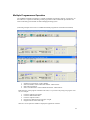
1
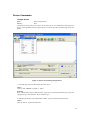
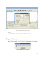
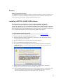
LABTOOL-848XP
Turbo Gang Programmer
User's Manual
2006/11/02 Revision A0.4
Copyright Notice
This document is copyrighted, 1998-2006 by Advantech Equipment Corp.. All rights are reserved.
Advantech Equipment Corp., reserves the right to make improvements to the products described in
this manual at any time without notice.
No part of this manual may be reproduced, copied, translated or transmitted in any form or by any
means without the prior written permission of Advantech Equipment Corp. Information provided in
this manual is intended to be accurate and reliable. However, Advantech Equipment Corp. assumes
no responsibility for its use nor for any infringements upon the rights of third parties which may
result from its use.
Acknowledgments
IBM, PC AT and VGA are trademarks of International Business Machines Corporation.
MS-Windows are trademarks of Microsoft Corporation.
2
How to use this manual
Thank you for purchasing the LABTOOL-848XP Turbo Gang Programmer. We designed this
manual to help you quickly and easily set up and use your LABTOOL-848XP. You can use the
manual in two ways:
Step by step:
The manual should be used in conjunction with the On-line help contained in the LABTOOL848XP software. Once you've installed the LABTOOL-848XP and the software, you shouldn't need
this manual again. You can just press 'F1' in the program and context sensitive help will guide you
through the processes.
Quick Start:
Our special Quick Start section gives experienced users the information they need to setup the
LABTOOL-848XP and software, and basic guidelines on using the LABTOOL-848XP. If you need
more information, you can refer to the rest of the manual. If you have any problems, you can work
through the manual step by step for easy troubleshooting.
If you have any questions, feel free to call your local distributor or sales representative.
Software update:
Please visit our website at www.aec.com.tw to update the software.
3
Packing list
Before you begin installing your LABTOOL-848XP, please make sure that the following materials
have been shipped:
• 1 LABTOOL-848XP turbo gang programmer
• 1 Power cord
• 1 parallel cable
• 1 USB cable
• 1 CD-ROM containing the Windows software
4
Contents
Chapter 0 Quick Start................................................................... 7
Quick Start ................................................................................ 8
Chapter 1 General Information.................................................... 9
Introduction............................................................................. 10
Features................................................................................... 10
Using the LABTOOL-848XP Software.................................. 12
Chapter 2 Installation ................................................................. 14
Minimum PC System Requirements....................................... 15
Installing the LABTOOL-848XP Software ............................ 15
Installing the LABTOOL-848XP .......................................... 15
Upgrading the LABTOOL-848XP Software .......................... 15
Chapter 3 Command Hierarchy................................................. 16
LABTOOL-848XP Command Hierarchy............................... 17
Chapter 4 Operation ................................................................... 18
LED Display on Each Socket ............................................... 19
LED color key......................................................................... 19
File Commands ..................................................................... 19
Save Buffer ............................................................................. 19
Load File ................................................................................. 20
Exit to Window....................................................................... 21
Project Commands ............................................................... 21
Save Project ........................................................................ 21
Load Project ........................................................................ 21
Device Commands................................................................. 22
Change Device .................................................................... 22
Mass-production Mode ……………………………………...23
Editing the Buffer .................................................................. 24
Blank Checking a device ....................................................... 25
Reading a device .................................................................... 25
Programming a device ............................................................ 25
Verifying a device................................................................... 26
Memory Protect ...................................................................... 27
Erasing a device ...................................................................... 27
Configuration .......................................................................... 27
Options................................................................................... 28
Modify Algorithm Parameters ................................................ 28
Device operation options ........................................................ 29
Module options ....................................................................... 31
Parallel Port............................................................................. 32
Statistic Option ....................................................................... 33
Diagnostics............................................................................. 34
Self Test .................................................................................. 35
Chapter 5 Using Adapters ......................................................... 36
Adapter requirements.............................................................. 37
5
Appendix A Error Messages...................................................... 40
Error Messages ....................................................................... 41
Appendix B USB Software General Information ..................... 43
Feature .................................................................................... 44
Installing LABTOOL-848XP USB software.......................... 44
Multiple Programmers Operation ........................................... 45
6
0
CHAPTER
Quick Start
7
Quick Start
0-1) This CD-ROM only has LABTOOL-848XP‘s parallel port software.
0-2) The parallel port must be EPP mode or ECP mode or BPP mode, the EPP mode is
recommended.
0-3) You could download the USB software “β version” from our website: www.aec.com.tw
1)
The LABTOOL-848XP must be turned off before you install its software.
2)
Install LABTOOL-848XP’s software then restart your PC or notebook.
3)
Turn on your LABTOOL-848XP and run its software.
4) Select the chip type to be programmed first.
Use the Hot key “ALT-C”, then type the complete part number of the chips to be programmed;
or use the mouse to select the correct part number.
5) Load the design file into the buffer.
Use the Hot key “ALT-L”, then specify the origin of the file and load.
6) Alternatively, you can read a master chip into the buffer instead of a design file.
The default master socket is socket 0. By putting a chip into socket 0 and performing the Read
operation (Hot key ALT-R), you can transfer the chip’s contents into the buffer.
You can also select any socket as the master socket. Go to the main menu, select the module
options (Hot key F5), then set the master socket, insert a master chip into the master socket, and
perform Read.
7) Insert 8 chips of the same type into the 8 ZIF sockets, set the device operation option (Hot key
F4), then perform Program (Hot key ALT-P). You can now program the 8 chips simultaneously.
8) To speed up throughput, a user can change the mode to Mass production mode (Hot Key Alt-M).
After entering this mode, the LABTOOL-848XP will program chips automatically after they are
properly inserted into the socket. LABTOOL-848XP has both a standard mass production mode
and a concurrent mass production mode. Standard mode allows the LABTOOL-848XP to
program 8 devices at the same time. Concurrent mode divides the 8 sockets into two groups,
group 1 comprised of sockets 0-3 and group 2 comprised of sockets 4-7. Chips in group 1 can be
programmed while chips are inserted or unloaded in group2. After the programming of chips in
group1 is finished, LABTOOL-848XP automatically programs the chips in group2.
A user can enable the insertion timer and adjust the timer. Enabling the timer will allow
LABTOOL-848XP to automatically shutdown a poor contact socket upon timeout of a user-set
timer period. LABTOOL-848XP then automatically programs the chips in the remaining good
sockets. The insertion timer default setting is 5 seconds. When the insertion timer is disabled,
the user will have to either correct the insertion error or press the ignore key to continue
programming after a poor contact socket is discovered.
9) LABTOOL-848XP also automatically keeps a running total of all chips that have been through
programming and all chips encountering programming failures. A user can input a target
quantity of chips to be programmed and an allowable number of programming failures. An
alarm message option provides a message to the screen alerting the user to either the target
quantity of chips being reached, or the allowable number of failures being reached.
10) For a detailed explanation of the device operation options, please refer to Chapters 3 and 4.
8
1
CHAPTER
General Information
9
Introduction
The LABTOOL-848XP is a PC-based gang programmer that works through your PC's parallel port.
It features eight fully isolated 48-pin ZIF sockets, extremely high throughput, standard 5 V and 3 V
chip support, production piece counts, and device insertion and continuity checks, all within a
PC-based design. Device updates are disseminated through software, giving our customers quicker
and more flexible access to new chip support. LABTOOL-848XP future software updates in
EPROM, EEPROM, and FLASH technology will include 87C5x, 89C5x, and PIC16Cxx
microprocessor support. The LABTOOL-848XP was designed with flexibility in mind. If a
customer has special chips that are not in our standard support list, we can provide special programs
which will allow the LABTOOL-848XP to perform as a customized special production gang
programmer.
Features
Universal adapter for Flash chips
The LABTOOL-848XP is designed to meet your future needs in high density Flash chips. Using the
resources of your PC, it supports 32 K bit up to 256 M bit memory chips without upgrading its
hardware. The LABTOOL-848XP also has a universal adaptor which accommodates 48-pin TSOP,
44-pin PSOP, 40-pin TSOP, and 32-pin TSOP Flash chips, which eliminates the need to buy
multiple adapters and saves you money.
Unbeatable speed through semi-concurrent programming technology
The LABTOOL-848XP's on-board intelligence reduces system overhead to a minimum. It can
program eight Flash chips of 8 MB capacity (such as Intel 28F800B3, for example) within 45
seconds. An experienced programmer can program thousands of high-density chips per day.
Furthermore, the LABTOOL-848XP supports two programming modes. In standard programming
mode, the LABTOOL-848XP automatically programs all eight chips after all eight pieces have been
inserted into the sockets. In semi-concurrent programming mode, a user can divide the 8 sockets into
two groups (of 4 sockets each). By using the technique of programming 4 chips while
simultaneously removing and inserting the other 4 chips, a customer can increase throughput. This
also allows interface with the fine pitch pick and place handler for high-density fine pitch chips.
Statistic Functions
The LABTOOL-848XP automatically keeps a running total of all production pieces attempted and
all production pieces failed. Users can input a target quantity of chips to be programmed and an
allowable number of failures. An alarm function can be enabled to send a message to the screen
alerting the user to either the target quantity of chips being reached, or the allowable number of
failures being reached.
Fully isolated ZIF sockets
The LABTOOL-848XP has fully isolated (> 1 M ohms) circuits for each socket's address/data
bus/control lines. Each socket has its own built-in Vcc and Vpp current-limiting circuitry. A
defective device in one socket will not affect the devices in or programming integrity of the
remaining sockets.
Device-insertion and continuity checks - No mistakes!
The LABTOOL-848XP performs device-insertion and continuity checks before programming each
device. It can detect poor pin contact, upside-down device insertion, incorrect position, and pin
number mismatch. This function protects your pocketbook by preventing expensive chip damage
caused by operator error.
Auto-sensing and self-programming
The LABTOOL-848XP has implemented patented technology to meet mass-production
requirements. When a chip fails the device insertion check, the LABTOOL-848XP waits for an
10
operator adjustable time. If the operator fails to correct the improper insertion within the selected
time period, the socket with the improper insertion is shutdown and the other chips are automatically
programmed.
Independent module design
The LABTOOL-848XP is designed to achieve a minimum of down time. Its 8 sockets are divided
into 4 identical modules having two sockets each. Each module is independent of the other three
modules. If one module fails, the customer can continue to operate the other three modules without
sacrificing the turnaround time to repair. Extra modules are available to customers in spare kits.
Project file "Save and Load"
You can save the program configuration project file which contains the device selection, the buffer
data and all of the program setup options. This file can be recalled at any time for future use without
having to go through the setup procedure again. This allows you to pass your design file to the
production department without mistakes. You can also read the data from a device into the buffer
from any of the 8 sockets, according to your specification.
Variable VCC with one or two-pass verification
The LABTOOL-848XP allows users to select the verification voltage after chip programming is
completed, e.g., VCC +/- 5%, VCC +/- 10%. VCC can range from 2 V to 7.5 V. Verification
ensures that the chips have been properly programmed, with no data retention problems.
LABTOOL-848XP Diagram
11
Device support summary
General EPROM: 27xxx series 32 K to 32 Mb with 8/16 bit data width.
Flash EPROM: supports NOR, NAND, AND, DI-NOR, and EEPROM technology
29xxx, 5 V / 3 V Flash, 28Fxxx 12 V / 5 V / 3 V Flash from all major chip vendors.
Microprocessor: (Future release through software update)
Intel 87C5x compatible, ATMEL 89C5x compatible, Micro chip PIC16Cxx.
Specification:
Socket and pin driver:
8 fully isolated 48 pin ZIF sockets with receptacle, over 1 M ohm resistance between each socket.
Four DACs for VCC, VPP1, VPP2 and VPP3 with 8 bit resolution.
VCC range 2 V to 7.5 V, resolution 50 mV
VPP1, 2 & 3 range 5 V to 16 V, resolution 100 mV
Overcurrent protection on all voltage sources
Logic level 5 V to 2.7 V programmable by software
Device Operation: Read, blank check, insertion/contact check, verify, check sum, erase chip,
program, memory protect, edit buffer, configuration, load file, save file, project file load/save
File format: Binary, Intel HEX, Intel extend HEX, Motorola S, HP64000ABS, TEK HEX, straight
Hex
General
Power: 100 VAC to 240 VAC, 47-63 Hz auto switch
Power consumption: 65 W
Operation temperature: 5 to 45 °C (41 to 113 °F)
Safety: CE & LVD certified
Weight: 8.5 kg net, 10 kg shipping weight
Using the LABTOOL-848XP Software
Menus
Accessing the menus can be done in two ways:
Use the mouse and click on the menu option displayed at the top of the screen. A pull-down menu
will appear, and you can select the option you desire by clicking on that option.
If you do not have a mouse available, you can also use the keyboard to access the menus. Press
[F10] to activate the main menu bar.
Select the sub-menu that you want to use with the left and right arrow keys, and press <ENTER> to
activate the sub-menu. Use the up and down arrows to select an option to execute. Press <ENTER>
to execute the command.
Hot-keys
Most of the options available on the menus can also be executed by pressing the hot-key associated
with that option. To see what the hot-key is for a certain option, look on the menu where the option
is located. If a hot-key is available, it will be displayed next to the option name.
12
Hot Keys
Main Menu
Sub Menu
Device Information
Information Line
Statistics
13
2
CHAPTER
Installation
14
Minimum PC System Requirements
O.S.: (1) Parallel port: Win 95/98/ME, Win 2000, Win XP, Win NT 4.0 or latest
(NT OS system, need NT System ADM).
(2) USB port: Win 98/ME, Win 2000 SP4, Win XP SP1/SP2 or latest.
CPU: PII 750 and above
RAM: 64 MB minimum, 128 MB recommended
HD: 16 MB of free hard disk space.
Interfaces: (1) D-25 connector with parallel port EPP or ECP or BPP mode, EPP mode is
recommended
(2) USB 1.1/2.0, USB2.0 is recommended
Installing the LABTOOL-848XP Software
Insert the CD into the PC's CD-ROM E: Drive.
In the file manager, you can select the E:\Setup and hit Enter; it will create a directory called
WLT848XP on your computer's C:\Programm Files\AEC\WL848XP path and will install the
LABTOOL-848XP software in this directory.
Following successful installation, restart your PC then run the software.
Installing the LABTOOL-848XP
1. Switch the PC and the LABTOOL-848XP off.
2. Connect the LABTOOL-848XP to a parallel port using the cable supplied.
3. Switch the PC on.
4. Switch the LABTOOL-848XP on.
Upgrading the LABTOOL-848XP Software
We provide quarterly formal releases of the LABTOOL-848XP software on our website. Monthly
temporary releases are also available on our website. Please download releases from our website at:
www.aec.com.tw
15
3
CHAPTER
Command Hierarchy
16
LABTOOL-848XP Command Hierarchy
File (Alt+F)
Project (Alt+J)
Device (Alt+D)
Options (Alt+O)
Diagnostics (Alt+I)
Save Buffer
Alt+S
Load File
Alt+L
Exit
Alt+X
Save Project
Alt+F1
Load Project
Alt+F2
Change
Alt+C
Mass Production Mode
Alt+M
Edit
Alt+E
Read
Alt+R
Blank Check
Alt+B
Program
Alt+P
Verify
Alt+V
Memory Prot/Prog Config
Alt+Y
Erase
Alt+K
Configuration
Alt+U
Parameters
F3
Operation
F4
Module Options
F5
Parallel Port
F6
Statistic
F7
Self Test
F8
17
4
CHAPTER
Operation
18
LED Display on Each Socket
Each of the 8 sockets in the LABTOOL-848XP has a three-color LED display to indicate the status
of the socket. Read this section carefully to avoid damage to chips.
Warning: Do not insert or remove a chip from a socket while the socket LED is
yellow!
LED color key
Blank
the socket is not active.
Green
the socket is active or the last operation result passed
Yellow
the socket is busy; don’t do anything until the LED turns Green or Red.
Red
the last operation resulted in failure; the socket is active and awaiting another operation.
Flashing LED, 5 Hz frequency. This mode only applies to insertion and contact checks of the
chips in the socket.
Flashing Green
the chip passed the continuity check.
Flashing Yellow
the socket is active and waiting for a chip to be inserted.
Flashing Red
the chip failed the insertion/continuity check, due to poor contact, incorrect chip
positioning, pin count mismatch, chip upside-down, pin short-circuit, or chip
damage.
File Commands
Save Buffer
Menu
Hot-key
File | Save Buffer
Alt+S
This option is used to save the memory buffer to a file on the hard disk.
Select a file (to overwrite!) using the mouse, or type the file name in the box provided. You can also
type in a file spec. (e.g. *.hex) at the Name prompt. This will display all the files of the specified
type, and you can then select the required file to overwrite.
ViewText
Certain file types contain header information. Click on this box to see this information. This will
display information similar to the following:
ABEL(tm) 3.00a FutureNet Div, Data I/O Corp.
Created on: 15-Sep-04 04:17 PM
PROM8908 pin configuration Ver 3.0
AEC Programmers
4 NOV 2004*
QP20* QF2194*
L0000
01101111111111111111111111111111
00000000000000000000000000000000
JEDEC file for: P16V8R
Output File Format
Select the file format of the output file.
19
From Buffer Mode
This mode functions as follows:
Normal
Every byte is written to the output file.
File shuffling
Odd
Every Odd byte is written to the output file.
Even
Every Even byte is written to the output file.
The following four options are used to write the buffer into four different files:
1st byte of 4
This writes the bytes 1, 5, 9, 13, ... into the output file.
2nd byte of 4
This writes the bytes 2, 6, 10, 14, ... into the output file.
3rd byte of 4
This writes the bytes 3, 7, 11, 15, ... into the output file.
4th byte of 4
This writes the bytes 4, 8, 12, 16, ... into the output file.
Load File
Menu
Hot-key
File | Load File
Alt+L
This option loads a file from disk into the memory buffer. The type of files that can be loaded for a
device depends on the device type.
Select a file to load using the mouse, or type the filename in the box provided. You can also type in
a file spec. (e.g. *.hex) at the Name prompt. This will display all the files of the specified type, and
you can then select the required file to load.
ViewText
Certain file types contain header information. Click on this box to see this information. This will
display information similar to the following:
ABEL(tm) 3.00a FutureNet Div, Data I/O Corp.
Created on: 15-Sep-04 04:17 PM
PROM8908 pin configuration Ver 3.0
AEC Programmers
4 NOV 2004*
QP20* QF2194*
L0000
01101111111111111111111111111111
00000000000000000000000000000000
JEDEC file for: P16V8R
Auto Format Detected
The software automatically detects the format of the file that is to be loaded. If the desired format of
the file differs from the format detected, select the correct file format.
From File Mode
This option indicates which bytes must be read in the input file. Select the required format.
To Buffer Mode
This option indicates where the byte previously read is to be written. This enables you to 'build' the
memory buffer from several files.
20
From File Address
If only a selected range is to be read from the input file, fill in the address that will contain the first
byte into this box, and the size of the buffer to be read in Size.
To Buffer Address
If the data read is to be copied into a specific area of the buffer, fill in the starting address here.
Size
This box contains the buffer size. By default it is the same size as the device size. If you want to
download a file into memory that is bigger than the active device, insert the size here (or in Options |
Operation Options).
Clear Buffer Options
Four options are available during memory buffer data loading. The default option is to clear the
buffer to its blank state prior to data loading.
Disable
This option leaves the original buffer data unchanged, but then overwrites it with the contents of the
newly loaded file.
Blank state
This option clears the buffer to the device blank state (using command 00 or FF, depending on
device selection), then overwrites the buffer during file loading.
0x00
First clears the buffer of its contents using command 00, then overwrites the buffer with the new file
contents
0xFF
First clears the buffer of its contents using command FF, then overwrites the buffer with the new file
contents.
Exit to Window
Menu
Hot-key
File | Exit to Window
Alt+X
Quit the LABTOOL-848XP program and exit.
Project Commands
Save Project
Menu
Hot-key
Project | Save Project
Alt+F1
This option saves the current setup of the LABTOOL-848XP software into a project file. The file
includes devices selected, buffer data, operation options setup and device configuration setup. You
can also attach a footnote to this project file. The project file acts as a macro, eliminating the need to
go through each procedure during future programming sessions.
Load Project
Menu
Hot-key
Project | Load Project File
Alt+F2
This option loads the desired project file. After the project file has been loaded, you can
immediately program the chip using the data and setup functions selected.
21
Device Commands
Change Device
Menu
Hot-key
Device | Change Device
Alt+C
This option is used to select a new device as the active device. It is important to select the correct
device, as the algorithms used to program devices are device-specific. The following screen will
appear:
Figure 4.1 Screen for selecting Change Device
1. Select the type of device that will be the active device.
Mouse
Click on 'All', 'EPROM' or 'Flash' or ‘ MCU’.
Keyboard
Press TAB until the cursor is flashing in the 'Type' box. Use the up and down arrows to go to the
appropriate type. Press the space bar to select the type.
2. Enter the part number, the manufacturer number, or parts of both in the 'Search' box.
Mouse
Click on 'Search'. Type in the characters.
22
Keyboard
Press TAB until the cursor flashes in the 'Search' box. Type in the known characters.
All the devices that satisfy this partial information will be displayed.
Use the mouse to select a device, and click 'Ok'. If you are not using a mouse, use the TAB key to
skip between the various screens, and use the arrow keys to move around in each screen.
Mass production Mode
Menu
Hot-key
Device | Mass Produce
Alt+M
The LABTOOL-848XP is a mass-production programmer for manufacturing. When placed in mass
production mode, all keyboard and mouse functions are disabled and the operator needs only to
insert the chips into the ZIF sockets, wait until the green LED next to each socket lights up, remove
the programmed chips and insert new chips. Anyone can do the job well without special training or
skills. Since all keyboard and mouse functions are disabled, the possibility of errors being caused by
pressing the wrong keys or changing the buffer's contents are eliminated.
In mass production mode, the LABTOOL-848XP first performs an insertion test and an ID check on
newly inserted chips. It then automatically programs the chip. In mass production, the LABTOOL848XP can be set to either of two modes: standard mode or concurrent mode. In standard mode,
LABTOOL-848XP programs the devices in all 8 ZIF sockets at one time. In concurrent mode, on
the other hand, the sockets are divided into two groups. Sockets 0-3 comprise group1 and sockets 47 comprise group 2. During operation under concurrent mode, group 1 devices are being
programmed while the operator unloads and inserts chips in the group 2 sockets.
Note:
The insertion test must be enabled to use mass-production mode!
23
Figure 4.2 Standard mass production mode screen
Figure 4.3 Concurrent mass production mode screen
An insertion timer is included for use with the insertion test. When a chip fails an insertion test and
the insertion timer is disabled, the LABTOOL-848XP will alert the operator to the failure and
require either that the problem be corrected or that the operator acknowledge the failure before
continuing with programming. When a chip fails and the insertion timer is enabled, the LABTOOL848XP waits the amount of time set into the insertion timer. This is to give the operator time to
correct the error. If the error is not corrected in time, the error socket shuts down and all the devices
in good sockets are programmed. The insertion timer default time is 5 seconds.
Editing the Buffer
Menu
Hot-key
Device | Edit
Alt+E
This function is used to edit the memory buffer. The memory buffer contains the last file
downloaded from disk into memory. If no file has been downloaded from disk into memory since
the LABTOOL-848XP was switched on, the memory buffer will contain "garbage".
The screen that is displayed is dependent on the type of device that is currently active.
The purposes of the buttons displayed are as follows:
Radix
24
This button controls the display of the memory address in Hex/decimal format. If the address is
currently displayed in decimal format, clicking this button will convert and display the address in
Hex.
Fill
This option is used to fill a block of memory with a specified value. It needs the starting address, the
ending address and the value to be copied into this block of memory.
Copy
This function copies a block in memory to a new address. It requires the starting address, the ending
address and the address the block must be copied to.
Search
This function searches for a specified "search-string". It requires input of the search-string to search
for.
Undo
As you make changes to the memory buffer, the changes on the current page are highlighted. If you
choose this option, it will reverse all changes made to the highlighted areas.
As soon as the changed memory positions move off the screen, or get deselected by another
command, the Undo command will not undo the changes.
Blank checking a device
Menu
Hot-key
Device | Blank Check
Alt+B
This option checks if the active device is in its erased state. It will return a message stating "Device
not blank!" at the first occurrence of data in the device. The address where the data is found will also
be displayed.
Reading a device
Menu
Hot-key
Device | Read
Alt+R
This option reads a master chip into the memory buffer for duplication of the master chip. Prior to
executing this command, a master socket must be designated and the master chip inserted into the
master socket. The default master socket is socket 0.
Programming a device
Menu
Hot-key
Device | Program
Alt+P
This option programs the active device with the contents of the memory buffer. When the
programming is complete, verification will take place. The type of verification depends on the
'verification options' set in the Options|Operation options menu.
25
Figure 4-4 Programming progress screen
Verifying a device
Menu
Hot-key
Device | Verify
Alt+V
This function compares the contents of the active device with the contents of the memory buffer. It
will display an error message and the address if it finds an address where the data differs. It will also
abort the process when this happens.
26
Figure 4-5 Device verification screen
Memory Protect
Menu
Hot-key
Device | Memory Prot/Prog Config
Alt+Y
This function is a device-specific command; it appears on the main menu only after chips having
this capability are selected. The function must be configured before use. When properly configured,
it can be selected and will automatically set memory protection on the chips immediately after they
have been programmed.
Erasing a device
Menu
Hot-key
Device | Erase
Alt+K
This function is a device-specific command; it appears on the main menu only after electronically
erasable chips have been selected. The function can be used to erase a desired memory range from a
chip.
Configuration
Menu
Hot-key
Device | Configuration
Alt+U
This function is a device-specific command for a single Flash chip with a software protect block, an
option register, configure word and lock bit. The function must be configured before use. When used,
27
the memory protect configuration data will be burned into the chip's memory and will protect
specified memory blocks.
Figure 4-6 Example of device-specific configuration screen
Options
Modify Algorithm Parameters
Menu
Hot-key
Options | Parameters
F3
This function allows a user to modify the programming parameters of the chips being programmed.
With the programming parameters for the selected chip appearing on screen, the user activates the
"modify algorithm screen" and changes the parameters by moving the cursor to the corresponding
field and changing the value to the desired value. If a value entered exceeds the allowable limits for
a given parameter, a warning will be flashed, together with allowable limits, after the user attempts
to confirm the setting by pressing "OK".
Warning:
Only experienced users should use this option, as it can damage
the device if it is used incorrectly.
28
Figure 4-7 Example screen: Modify algorithm parameters
If you want to program a device that is not supported by the LABTOOL-848XP, do the following:
1. Select a device that uses the same programming algorithm as the device in question.
2. Modify the device programming parameters.
3. Program the device.
As the programming parameters are for temporary use only, they cannot be saved. After you select a
new device or exit the LABTOOL-848XP software the original parameters will automatically be
restored.
Device operation options
Menu
Hot-key
Options | Operation
F4
29
Figure 4-8 Example screen: Device-specific operation options
The following options can be set:
Start address, End address
This is the start and the end address of the edit buffer. If you want to program a certain area of a
device, you can change the start and end addresses accordingly.
This option is only displayed when the device can be programmed in this way.
When the end address is calculated, it divides the buffer size by (device-bits/8-bits). A 16 bit device,
of which the buffer size is 80 (Hex), will therefore have an end address of 3F.
When selecting a start or an end-address, you should align the buffer on the right boundary: singleword for 8-bit devices, double-word for 16-bit devices, etc.
Erase start/end address
This option is for electronically erasable Flash chips only. The default setting of this option will
erase the entire chip. However, a user can specify ranges of blocks to be erased; data in the
remaining blocks will be unchanged. A user should reference the chip data book or configuration
menu when setting the ranges of blocks to be erased.
Insertion Timer Enable/Disable
When the insertion timer is disabled and an error is detected during insertion testing, the
LABTOOL-848XP waits for the operator to either correct the error condition or to acknowledge and
bypass the error.
30
When the insertion timer is enabled, the LABTOOL-848XP waits a specified period for the operator
to correct the condition, and if no correction is made, shuts down the socket(s) reporting the error
and completes programming of the remaining sockets.
Insertion Timer
This option sets the time-out interval for the insertion test. When the insertion timer is enabled and
an insertion error is detected, if the operator fails to correct the problem within the interval set, the
LABTOOL-848XP will automatically shutdown the error socket and complete programming of the
remaining sockets. If multiple errors exist in different sockets and the operator corrects one of the
sockets, the timer resets and waits the specified time for each succeeding error. Time-out intervals
can be set from 1 to 999 seconds. The default value is 5 seconds.
Insertion Test
This option performs the device-insertion check of the chips in the sockets. The insertion check
includes poor pin contact, pin count mismatch (the pin count of the chip designated in the software
does not match the pin count of the actual chip in the socket), device in wrong position, device
upside-down, short-circuit between pins, and chip damage. Results are displayed at each socket's
LED.
Device ID Check
This option performs a device signature and manufacturer match test. With the chip selected and
plugged into a socket, LABTOOL-848XP checks the device ID and displays the results of each
check on the LED display.
Verify Passes
Checking this option will instruct the LABTOOL-848XP to perform device verification with the
buffer data when programming is complete. When verify passes is enabled, one of the three verify
options (as described below) must be set.
Verifying Options
The following three options are available for verification of data retention following programming:
verify twice with 5% VCC, verify twice with 10% VCC, and verify once with VCC. These options will
only be enabled if the 'Verify passes' option (see above) is enabled.
(•) Twice VCC ± 5 %
When this option is selected, the LABTOOL-848XP will do two verify passes on the device: one
using VCC + 5%, the other VCC - 5%.
Example:
IF VCC is 5.0 V, the LABTOOL-848XP will do one verify pass using a VCC of 4.75 V, and one using
a VCC of 5.25 V.
(•) Twice VCC ± 10 %
When this option is selected, the LABTOOL-848XP will do two verify passes on the device: one
using VCC + 10%, the other VCC - 10%.
Module options
Menu
Hot-key
Options | Module options
F5
31
This option is used to select the master socket location (default slot0), and enable/disable the socket.
Figure 4-9 Master socket selection, active socket selection
Parallel Port options
Menu
Hot-key
Options | Parallel Port
F6
This option is used to select parallel port location (default Auto Search). When a parallel port is a
specified I/O address, you could key in the address in hexadecimal code.
32
Figure 4-10 Parallel Port selection
Statistic Commands
LABTOOL-848XP can keep track of chip programming failures. The lower right-hand corner of the
Run Time Viewer screen contains two entries: Current Quantity and Total Fail. These quantities
automatically increment for every chip LABTOOL-848XP attempts to program, and for every
programming failure. Failures counted include chips that fail device ID check, blank check, verify
pass, protect, and unprotect. The user can input a target quantity of chips to be programmed in a
production run, and an allowable number of failures. An alarm feature can be set so that when the
target quantity or the allowable failures is reached, an alarm message is displayed on the screen to
alert the operator.
Statistic Option
Menu
Hot-key
Options | Statistic
F7
This command controls the setting of the Statistic Option. Select the command using the mouse or
tab key, or the hot-key Alt-T. The screen shown below will appear. Use the mouse or tab between
screen entries. Fill in the desired quantities for Target Quantity and Maximum Fail, and indicate
your choice for alarm enabling or disablement. Select the OK button and press enter to confirm your
selections.
33
Figure 4-11 Statistic option selection screen
Reset
This command clears the statistic report in the lower right corner of the screen.
Diagnostic Commands
LABTOOL-848XP can keep track of chip programming failures. The lower right-hand corner of
Manufacture recommends the user can run self-test of LABTOOL-848XP prior to each day’s
operation and remove all devices from the modules before starting.
Figure 4-12 Remove all the devices screen
34
Self Test
Menu
Hot-key
Diagnostics | Self Test
F8
The self-test routine including testing the parallel port, RAM, ROM and EEPROM of system, and
Pin driver, TTL driver, relay, D/A converter’s voltage drop and other parameter of all modules,
following is the example test result screen.
Figure 4-13 System and all modules self test screen
We wrote a file with serial number for the LABTOOL-848XP (ex: AE0509900001.rep), the user
could find out from C:\Program Files\AEC\WLT848XP (for Parallel port) or C:\Program
Files\AEC\WLT848UXP (for USB port). If you have any issues, you can send us the rep file
(AE0509900001.rep) for a rapid service from our website www.aec.com.tw
Figure 4-14 The Report file screen
35
5
CHAPTER
Using Adapters
36
Adapter requirements
The LABTOOL-848XP supports all 48-pin TSOP, 44-pin PSOP, 40-pin TSOP, and 32-pin TSOP
pin packages. You will need to order an adapter for non-DIL chip packages. You can order the
following available adapters to fit your needs. Other adapters will become available after release of
new chips.
Adapter Types
Adapter
Adapter Decsription
GDP-1305-48TSS
48 pin TSSOP adapter for Sharp LRS1305
GDP-130X-48TSS
48 pin TSSOP adapter for Sharp LRS1306 / 8
GDP-1611-48TS
48 pin TSOP adapter for MX29L1611
GDP-DIP-001
48 pin DIP adapter for Motorola HC705P6 / A, HC705P9, Atmel 90S44xx / 85xx
GDP-DIP-002
DIP adapter for Altera EPC1/2 and Atmel 17Cxxx, 17LVxxx PROM
GDP-DIP-003
DIP to DIP adapter for PIC 16C64 / 5A / 5B / 7 , 16C74A , 16C77 / 774 , 17LVxxx PROM
GDP-F016-56TS
56 pin TSOP adapter for intel 28F016/032S3/S5
GDP-F320-56SS
56 pin SSOP adapter for intel 28F320 / 640 / 128J5 / J3
GDP-F640-56TS
56 pin TSOP adapter for Intel 28F320 / 640J5 / J3
GDP-PLCC-4401
PLCC to DIP adapter for Motorola 44 pin PLCC 68HC705C8 / A
GDP-PLCC-4402
44 pin PLCC adapter for Motorola 68HC705C9 / A
GDP-SOIC-1601
16 pin SOIC Adapter for PIC12F629/675.
GDP-SOIC-1602
16 pin SOIC Adapter for ST M25P10/20/40 .
GDP-ST064-48TS
48 pin TSOP adapter for STM 29KW016/032/064.
GDP-TQFP-4401
TQFP to DIP adapter for Motorola 44 TQFP 68HC705C8 / A44
GDP-TSOP-2801
28 pin TSOP ( 8 * 14 mm ) adapter for Atmel 45DB161/081
LVT - NEC6411-85F
low voltage adapter for NEC uPD29F064115F9.
LVT-128K18-56U
56 pin VFBGA adapter for Intel GE28F128K18.
LVT-128K18-64E
64 ball EBGA adapter for Intel RC28F128K18
LVT-128K3-56U
56 ball VFBGA adapter for Intel GE28F128K3
LVT-128K3-64E
64 ball EBGA adapter for Intel RC28F128K/640K3
LVT-128W18-56U
56 ball VFBGA adapter for Intel GE28F128W18
LVT-128W30-56U
56 ball VFBGA adapter for Intel GE28F128W30
LVT-2240WY-80F
80 pin FBGA adapter for Intel RD38Fxxx WY MCP .
LVT-2240WZ-80F
80 pin FBGA adapter for Intel RD38FxxxxWZ MCP.
LVT-256K18-63VF
63 pin VFBGA adapter for Intel GE28F256K18C.
LVT-256K18-64E
64 pin EGBA adapter for Intel RC28F256K18C.
LVT-256K3-63VF
63 pin VFBGA adapter for Intel GE28F256K3C.
LVT-256K3-64E
64 pin EBGA adapter for Intel RC28F256K3C.
LVT-320D18-56U
uBGA adapter for Intel 28F320D18 ( 1.8Vcc, I/O )
LVT-6408W18-80F
80 pin uBGA adapter for Intel 28F6408W18 CSP Flash.
LVT-6408W30-80F
80 pin uBGA adapter for Intel 28F6408W30 CSP Flash.
LVT-640K18-56U
56 pin VFBGA adapter for Intel GE28F640K18C.
LVT-640K3-56U
56 pin VFBGA adapter for Intel GE28F640K3C.
LVT-640W18-56U
uBGA adapter for Intel 28F320 / 640 / 128W18 ( 1.8Vcc, I/O ) [ 7*8 ball , 0.75 mm ]
LVT-640W30-56U
uBGA adapter for Intel 28F320 / 640W30 ( 1.8Vcc, 3V I/O )
37
Adapter Types
Adapter
Adapter Decsription
LVT-ADS323-48TS
1.8V low voltage adapter for AMD 29DS32X ( 48TSOP )
LVT-MT6428-64F
64 pin FBGA adapter for Micron MT28C6428P20/P18 .
LVT-ST432-64F
64 pin FBGA adapter for ST M36DR342A/B.
PLCC-3228-11
32 pin PLCC to 28 pin DIP adapter ( NC=1,12,17,26 ) for E/EEPROM below 512k <<
29LV256 / 27C512 / 27C256R >>
PLCC-3232-11
32 pin PLCC to 32 pin DIP adapter for E / EEPROM with 1 M and up
PLCC-4440-01
44 pin PLCC adapter ( NC= 1,13,23,33 ) for 44 pin PLCC package 16 bit EPROM
PLCC-4440-02
44 pin PLCC adapter ( NC= 1,12,23,34 ) for 44 pin PLCC package 875X processor
QFN-2828-01
28 pin MLF adapter for PIC 16F87X family
SDP - ST320 - 48U
48 pin BGA ( 0.75 mm pitch ) adapter for ST28W320CT
SDP-1329-64F
72 pin CSP ( 8mm * 11mm ) adapter for SHARP LRS1329 / 1340/1349/1356
SDP-1331-64F
72 pin CSP ( 8mm * 11mm ) adapter for SHARP LRS1331 / 37 / 41 / 42, LRS1357 / 58 ,
LRS1362 / 63 / 64 / 65
SDP-1826-64F
64 ball FBGA adapter for SHARP LRS1826 and ATMEL AT52BR3244/3248
SDP-3204-64F
72 pin CSP adapter for Intel RD28F1602 / RD28F3204
SDP-3224-100Q
100 pin QFP adapter for STV0680
SDP-41DL16-69F
69 ball FBGA adapter for AMD 41DL16xx MCP
SDP-42DL32-73F
73 ball FBGA adapter for AMD 41DL32xx MCP
SDP-49PDL64-73F
73 pin FBGA Adapter for AMD Am49PDL640AG.
SDP-6408-64F
uBGA adapter for Intel RD28F3208C3B/T, 6408J3A
SDP-A128M-64E
64 pin EBGA adapter for AMD 29LV640MH/L, 29LV128MH/L.
SDP-A160-48F
FBGA adapter for AMD 29LV160 ( 0.8mm pitch ) Flash chips
SDP-A256M-56TS
56 TSOP adapter for AMD 29LV256MH/L.
SDP-A320-48F
48 pin uBGA adapter for AMD29DL32X ( 6 * 12mm size )
SDP-A320-63F
63 pin uBGA adapter for AMD29DL32X ( 8 * 14mm size )
SDP-A640-48F
FBGA adapter ( 0.8mm pitch ) for AMD 29DL640D
SDP-A642-64E
64 pin EBGA adapter for AMD29LV642D
SDP-A800-48F
FBGA adapter for AMD 29LV800 ( 0.8mm pitch ) Flash chips
SDP-AT128-64TQ
64 pin TQFP adapter for Atmel Atmega64/128.
SDP-C923-68
68 pin PLCC adapter for Microchip PIC 16C923/924
SDP-D554-96F
96 pin FBGA adapter for Fujitsu MB84VF5F 5F4J2
SDP-D641-52TS/W
52 pin TSOP adapter for MitsuBishi M6MG321S4TP M6MGT641S8TP
SDP-EBGA-001
64 pin EBGA ( 1.0mm pitch ) adapter for Intel 28F800 / 160 / 320F3 / C3
SDP-EBGA-002
64 pin EBGA ( 1.0mm pitch ) adapter for Intel 28F320 / 640 / 128J3A
SDP-EBGA-003
64 pin EGBA adapter for Intel 28F128J3C.
SDP-F016-56TS
56 pin TSOP adapter for intel 28F016 / 032S3 / S5 Flash memory
SDP-F1316-64F
72 pin FBGA ( 0.8mm pitch ) adapter for SHARP LRS1306 / 1316A
SDP-F2108-56F
56 pin FBGA adapter for Fujitsu 84VD2108X MCP.
SDP-F2228-56F
56 pin FBGA Adapter for Fujitsu MB84VD22280/90FE. [ 7*9 ball ]
SDP-F2238-56F
56 Pin FBGA Adapter for Fujitsu MB84VD2238X/39X EF/J. [ 7*11 ball ]
SDP-F256-80F
80 ball VFBGA adapter for Intel RD28F256SJ3AM, RD28F192SJ3AM, RD28F128SJ3AM
SDP-F320-56SS
56 pin SSOP adapter for intel 28F160/320S3/S5
38
Adapter Types
Adapter
Adapter Decsription
SDP-i320-48U
48 pin u BGA adapter for Intel 28F320B3 / C3 , 28F160B3/C3 ( 0.75 mm pitch )
SDP-i320-48VF
48 pin VFBGA adapter for Intel 28F320B3C, 28F320C3C, 28F160C3C
SDP-i640-48VF
48 ball VFBGA adapter for Intel GE28F640C3
SDP-M157-52TS/W
52 pin TSOP adapter for Mitsubishi M5M29KE-157MT
SDP-M160-48U
48 pin uBGA adapter for Micron 28F160C3 ( 0.75 mm pitch )
SDP-MT322-48U
uBGA Adapter for Micron MT28F322P3FJ stack flash.
SDP-S160-48U
48 pin UBGA adapter for SHARP 28F160BJE
SDP-SDA555-52SD
52 pin SDIP Adapter for Micronas SDA555XFL
SDP-SST1621-56F
56 pin FBGA adapter for SST34HF1621/1601
SDP-SST800-48F
48 pin FBGA adapter SST 39VF800/160
SDP-ST064-56TS
56 pin TSOP adapter for ST 58LW064A
SDP-TH1282-48F
48 pin FBGA Adapter for Toshiba TC581282AXB, 58FYM6
SDP-TH2580-56F
56 pin FBGA Adapter for TOSHIBA TH50VSF2580/1AASB.
SDP-TH5782-60F
60 pin FBGA Adapter for TOSHIBA TH50VPF5782/83AASB
SDP-UNIV-20SO
20 pin SOIC ( 300mil ) universal adapter to support 16 - 20 pin SOIC package devices <<
0.762 cm >>
SDP-UNIV-20SO/200
20 pin SOIC ( 207mil ) universal adapter for 8 - 20 pin chips << 0.525 cm >>
SDP-UNIV-28SO/300
28 pin SOIC ( 300mil ) universal adapter to support 20 - 28 pin SOIC package devices <<
0.762 cm >>
SDP-UNIV-28SS/200
28 pin universal SSOP adapters for 200mil x 0.65mm pitch << 0.525 cm >>
SDP-UNIV-28TS
28 pin TSOP universal ( 8mm x 14mm ) adapter
SDP-UNIV-32TS
32 pin TSOP ( 8mm x 20mm ) universal universal adapter for 32 pin TSOP Flash memory
SDP-UNIV-32TS/W
32 pin TSOP ( 8mm x 14mm ) universal adapter for 32 pin TSOP Flash memory
SDP-UNIV-40TS
40 pin TSOP ( 10mm x 20mm ) universal adapter for 40 pin TSOP Flash memory
SDP-UNIV-40TS/W
40 pin TSOP ( 10mm x 14mm ) universal adapter for 40 TSOP Flash memory
SDP-UNIV-40TSS
40 pin universal TSSOP adapter
SDP-UNIV-44
44 pin PLCC universal adapter
SDP-UNIV-44C
44 pin PLCC ( clamshell socket ) universal adapter
SDP-UNIV-44PSO
44 pin PSOP universal adapter for 44 pin PSOP Flash memory
SDP-UNIV-44Q
44 pin PQFP universal adapter
SDP-UNIV-44TQ
44 pin TQFP universal adapter
SDP-UNIV-44TS
44 pin TSOP universal adapter for Samsung / Toshiba 44 pin TSOP NAND Flash memory
SDP-UNIV-48TS
48 pin TSOP ( 12mm x 20mm ) universal adapter to support 48 pin TSOP Flash memory
SDP-UNIV-48TS/W
48 pin TSOP ( 12mm x 14mm ) universal adapter to support 48 pin TSOP Flash memory
SDP-UNIV-48TSS
48 pin universal TSSOP universal adapters for Flash ( 0.4mm pitch, 10 x 14mm )
39
A
APPENDIX
Error Messages
40
Error Messages
This function is not supported in demo mode !
When the LABTOOL-848XP is not activated, some functions may be inhibited.
Illegal range of erase address setting ! Retry again !
The address range for an erase command must match the sector edge.
Time-Out error !
The LABTOOL-848XP does not respond when the system times out.
Cannot open file : XXXXXXXX !
The file was not found or a disk error occurred.
Device ID Code unmatched !
The current chip's ID will be displayed.
File write error !
Illegal file name or disk error.
The LABTOOL-848XP detected an error when writing a file to disk.
Check that there is enough space on the disk to hold the file. Also check that the disk is not writeprotected. This might happen on a network if you are a user that does not have rights to the directory
you want to save the file to. Use another directory or disk.
File read incomplete !
The user break .file format was unmatched or a disk error occurred during file reading.
LABTOOL-848XP not found, Do you want to retry ?
41
The LABTOOL-848XP software does not detect the LABTOOL-848XP on one of the parallel ports.
Press enter to retry. Press Esc to enter demo mode.
Make sure the power on the LABTOOL-848XP is on. Also check the parallel connection between
the PC and the LABTOOL-848XP. If the LABTOOL-848XP shares the parallel port with another
device, remove the other device or move the LABTOOL-848XP to its own port.
LABTOOL-848XP power off or disconnected from PC !
The LABTOOL-848XP software does not detect the LABTOOL-848XP on one of the parallel ports.
Make sure the power on the LABTOOL-848XP is on. Also check the parallel connection between
the PC and the LABTOOL-848XP and between the PC and the printer. If the LABTOOL-848XP
shares the parallel port with another device, remove the other device or move the LABTOOL848XP to its own port.
Other Error Messages
The following list of error messages uses the code XXXX, where XXXX can be Read; Verify/ Blank
Check; Program; Erase; or Memory Protect. Aborted has the same meaning as user break.
XXXX Aborted !
XXXXX error found !
XXXX error on Module X Address XXXXh !
42
B
APPENDIX
USB Software General Information
43
Feature
Multiple programmers Operation
The LABTOOL-848XP programmer is capable of multiple programmers support. A single PC, via
the USB bus, is capable of controlling several programmers. This combination provides the user
with an extremely powerful and versatile multiprogramming system
Installing LABTOOL-848XP USB Software
Recommended O.S. and USB specifications for LABTOOL-848XP with USB port
The LABTOOL-848XP programmer is workable on the Win98SE/ME, Win2000+SP4,
WinXP+SP1, WinXP+SP2. We recommend the Win2000+SP4 or WinXP+SP2 for LABTOOL848XP with USB interface, because you do not install 3rd party USB hub or host device drivers on
these operating systems. The DATAMA-848XP is operated on USB1.1 and USB 2.0 specifications.
We recommended USB2.0 to operate the LABTOOL-848XP with USB port.
Installing LABTOOL-848XP USB software
(1) Download the LABTOOL-848XP USB software β version from www.aec.com.tw.
(2) Turn the LABTOOL-848XP programmer power off.
(3) Install the LABTOOL-848XP’s USB software, the software will be installed into the path
C:\Program Files\AEC\WLT848UXP
(4) Plug the USB cable into the PC and LABTOOL-848XP USB ports.
(5) Turn on the LABTOOL-848XP programmer power on.
(6) The operating system automatically detected a corresponding USB driver for LABTOOL848XP. When you see a message of digital signature of the operating system, please press
“Continue Anyway”.
,
(7) Run the LABTOOL-848XP USB software. The software selecting path is StartÆ All
ProgramsÆ Advantech LabToolÆ LabTool-848XP (USB port)
Note: If the LABTOOL-848XP has hardware issues, please run the “Self Test ” (F8) function. The
software will generate a serial number file(ex: AE0509900001.rep) in the C:\Program
Files\AEC\WLT848UXP path, you can this file to us for a rapid service.
44
Multiple Programmers Operation
The LABTOOL-848XP programmer is capable of multiple programmers support. A single PC, via
the USB bus, is capable of controlling several programmers. This combination provides the user
with an extremely powerful and versatile multiprogramming system
(Following example is based on two LABTOOL-848XP programmers with software installed)
1.
2.
3.
4.
Install two programmers via the USB bus.
Start one instance of the LABTOOL-848XP - USB software.
Select the programmer.
Start a second instance of the LABTOOL-848XP - USB software.
Both instances of the program will behave the same, as if you were only using one program. You
can, for example:
1.
2.
3.
4.
5.
Load two separate project files.
Load two different data files.
Load two separate masters.
Program two different chips in groups of eight.
Program sixteen of the same chip.
There are several options available to display the application windows:
45
1.
2.
3.
Cascade
Tile window Horizontally
Tile window Vertically
To set these display options:
1. Right click the Task Bar
2. Click the display option: Cascade, Tile window Horizontally or Vertically
Setting up the mass production mode:
1. Click “Device” on the Tool Bar. (Note: can also press “Alt+M”)
2. Click “Mass Production Mode”
3. Select either standard or concurrent mode.
4. Click OK.
5. Reset or set the counter, if necessary.
6. Click OK.
It is best to program a full complement of chips at one time. For example, if you are programming
n concurrent mode, you need to install four chips at a time. If you are programming in standard
mode, install eight chips. The programmer is designed to automatically detect a full complement
of chips and then start the programming operation. Without a full complement of chips, the
operator will have to click the “Continue” button.
46