1
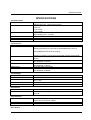
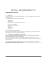
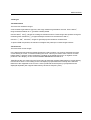
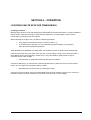
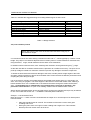
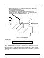
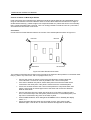
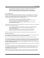
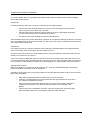
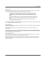
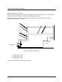
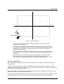
Polar Instruments Ltd.
Garenne Park
Rue de la Cache
St. Sampson
Guernsey
Channel Islands
GY2 4AF
England
http://www.polarinstruments.com
Fax: +44 (0)1481 252476
Email: [email protected]
MAN 129–9803
TONEOHM 950
OPERATOR
MANUAL
TONEOHM 950 MULTILAYER SHORTS LOCATOR
OPERATOR MANUAL
POLAR INSTRUMENTS LTD. HARDWARE WARRANTY
1.
Product Warranty. Product hardware is warranted to be free from defects in material and
workmanship during the Warranty Period (as defined below). Product hardware is warranted
to conform substantially to Polar’s then current (as of the date of Polar’s product shipment)
published user documentation during the Warranty Period. The Warranty Period is twelve (12)
months. Product support beyond these periods may be available at additional cost – consult
Polar for details.
2.
Warranty Claims. Polar shall incur no liability under this warranty if the end user fails to
provide Polar with notice of the alleged defect during the applicable Warranty Period and
within seven (7) days of delivery to end user or, if the defect would not have been reasonably
apparent on inspection, within seven (7) days of its discovery by end user. After receiving such
notice, Polar will notify the purchaser of its designation of one of the following problem
resolution methods:
Return to Factory: The allegedly defective goods must be returned to Polar within
seven days of Polar’s notice and in accordance with Polar’s instructions advised at the
time.
Other: Polar will use commercially reasonable efforts to repair, correct or work
around the problem by means of telephone support or other means reasonably
determined by Polar.
Polar shall incur no liability under this warranty if Polar’s tests disclose that the alleged defect
is due to causes not within Polar’s reasonable control, including alteration or abuse of the
goods. Under the Return to Factory alternative, if a Product is determined not to be defective
or to have a defect due to causes not within Polar’s reasonable control, Polar reserves the
right to apply a processing charge.
3.
Damage in Transit. End user must notify Polar and the carrier of any claim for damage in
transit within two (2) days of receipt of the damaged merchandise. Failure to do so may result
in the carrier and/or Polar refusing to accept liability in which case end user must pay the
purchase price as if the hardware had been delivered without damage.
4.
Polar’s Liability Polar’s liability, and end user’s sole and exclusive remedy, shall be limited to
the express remedies set forth in this Polar Hardware Warranty.
5.
Disclaimer of Warranties. POLAR MAKES NO OTHER WARRANTIES, EXPRESS, IMPLIED
OR STATUTORY, REGARDING PRODUCTS. ALL OTHER WARRANTIES AS TO THE
QUALITY, CONDITION, MERCHANTABILLITY, FITNESS FOR A PARTICULAR PURPOSE,
OR NON-INFRINGEMENT ARE EXPRESSLY DISCLAIMED.
6.
Limitation of Liability. POLAR SHALL NOT BE RESPONSIBLE FOR DIRECT DAMAGES IN
EXCESS OF THE PURCHASE PRICE PAID BY THE END USER OR FOR ANY SPECIAL,
CONSEQUENTIAL, INCIDENTAL, OR PUNITIVE DAMAGE, INCLUDING, BUT NOT
LIMITED TO, LOSS OF PROFITS OR DAMAGES TO BUSINESS OR BUSINESS
RELATIONS, WHETHER OR NOT ADVISED IN ADVANCE OF THE POSSIBILITY OF
SUCH DAMAGES, THE FOREGOING LIMITATIONS SHALL APPLY, NOTWITHSTANDING
THE FAILURE OF ANY EXCLUSIVE REMEDIES.
DECLARATIONS
EUROPEAN COMMUNITY DIRECTIVE CONFORMANCE STATEMENT
This product conforms to all applicable EC Council Directives, including:
EC Council Directive 89/336/EEC on the approximation of the laws of the Member States relating
to electromagnetic compatibility.
EC Council Directive 73/23/EEC on the harmonisation of the laws of the Member States relating
to electrical equipment designed for use within certain voltage limits.
A declaration of conformity with the requirements of these Directives has been signed by:
POLAR INSTRUMENTS (UK) LTD
11 College Place
London Road
Southampton
England
SO1 2FE
Harmonised standards applied in order to verify compliance with these Directives:
EN 50081-1:1992
EN 50082-1:1992
EN 61010-1:1993
iv
SAFETY
SAFETY
WARNING
The LIVE and NEUTRAL lines on this unit are BOTH fused.
This unit contains no user-serviceable parts. When the unit is connected to its supply, the opening of
covers or removal of panels is likely to expose dangerous voltages. To maintain operator safety, do not
operate the unit unless the enclosure is complete and securely assembled.
GROUNDING
This unit must be earthed (grounded); do not operate the instrument with the safety earth disconnected.
Ensure the instrument is connected to an outlet with an effective protective conductor terminal (earth). Do
not negate this protective action by using an extension cord without a protective conductor.
Note: This instrument is fitted with 3-wire grounding type plug designed to fit only into a grounding type
power outlet. If a special local plug must be fitted to the power cord ensure this operation is performed by
a skilled electronics technician and that the protective ground connection is maintained. The plug that is
cut off from the power cord must be safely disposed of.
Power cord color codes are as follows:
Europe
brown
blue
green/yellow
live
neutral
earth (ground)
United States
black
white
green
live
neutral
ground
v
TONEOHM 950 OPERATOR MANUAL
POWER SUPPLY
Check that the indicated line voltage setting corresponds with the local mains power supply. See the rear
panel for line voltage settings.
To change the line voltage settings refer the instrument to a skilled electronics technician. Instructions for
changing the line voltage settings are contained in the TONEOHM 950 Service Manual published by Polar
Instruments.
TONEOHM 950 OPERATION
This manual contains instructions and warnings which must be observed by the user to
ensure safe operation. Operating this instrument in ways other than detailed in this
manual may impair the protection provided by the instrument and may result in the
instrument becoming unsafe. Retain these instructions for later use.
The TONEOHM 950 is designed for use indoors in an electrical workshop environment at a stable work
station comprising a bench or similar work surface.
Use only the accessories (e.g. test probes and clips) provided by Polar Instruments.
The TONEOHM 950 must be maintained and repaired by a skilled electronics technician in accordance
with the manufacturer’s instructions.
If it is likely that the protection has been impaired the instrument must be made inoperative, secured
against unintended operation and referred to qualified service personnel. Protection may be impaired if,
for example, the instrument:
•
•
•
•
•
Shows signs of physical damage
Fails to operate normally when the operating instructions are followed
Has been stored for prolonged periods under unfavourable conditions
Has been subjected to excessive transport stresses
Has been exposed to rain or water or been subject to liquid spills
CAUTION
Electrical Isolation
Disconnect the board under test from the local mains supply (including ground) when using Track
Resistance, Plane Shorts and Trace ranges.
vi
SPECIFICATIONS
SPECIFICATIONS
Track Resistance
RANGES
ACCURACY
[Ω] RANGE
PROBE VOLTAGE
INDICATION
PROBE PROTECTION
Track Current
RANGES
ACCURACY
[Ω], 200mΩ, 2Ω, 200Ω, 20KΩ. Instruments with serial numbers below
005975 have a 2KΩ range instead of 200Ω.
+/-6% in 200mΩ
+/-5% in 2Ω
+/-4% in 200Ω
+/-5% in 20KΩ
High sensitivity, uncalibrated.
Approximately 40mΩ full scale.
60mV maximum.
Tone and meter in all ranges.
Protected to +/- 30V.
200mA, 2A, TRACE.
+/-15% in 200mA, 2A for track resistance between 25mΩ and 500mΩ.
Reading proportional to current when UNCALIBRATED LED is lit.
UNCALIBRATED LED lit during ranging.
TRACE SENSITIVITY
PROBE VOLTAGE
INJECTION CURRENT
INDICATION
PROBE PROTECTION
Track Voltage
RANGES
ACCURACY
INPUT RESISTANCE
INDICATION
PROBE PROTECTION
Plane Shorts
INDICATION
SENSITIVITY
Plane Stimulus
OUTPUT VOLTAGE
OUTPUT CURRENT
PROTECTION
Reading in TRACE is proportional to detected magnetic field strength.
Capable of detecting current flow with 200Ω resistance across Drive
Source.
600mV maximum in 200mA, 2A.
Not applicable in TRACE.
250mA maximum.
Not applicable in TRACE.
Tone and meter in all ranges.
Protected to +/- 30V in 200mA, 2A.
Not applicable in TRACE.
2mV, 20mV, 20V.
+/-4%, +/-15µV.
120Ω in 2mV, 20mV.
1MΩ in 20V.
Meter in all ranges. Tone in 2mV, 20mV.
Protected to +/- 30V
Tone, uncalibrated meter and fault direction arrows.
Adjustable for differing plane resistance. Capable of detecting shorts
up to 20Ω.
550mV maximum. Active only when PLANE SHORTS is ACTIVE and
outputs are connected to a plane.
700mA RMS maximum.
Each output separately fused.
Drive Source
vii
TONEOHM 950 OPERATOR MANUAL
OUTPUT VOLTAGE
0 to 550mV, adjustable.
AC in TRACE, DC in all other ranges.
Protected to +/- 30V.
PROTECTION
ENVIRONMENTAL OPERATING CONDITIONS
The instrument is designed for indoor use only under the following environmental conditions:
Altitude
Temperature
Relative humidity
Mains borne transients
Pollution Degree
Up to 2000m
+5°C to +40°C ambient
RH 80% maximum at 31°C — derate linearly to
50% at 40°C
As defined by Installation Category II
(Overvoltage Category II) in IEC664
2 (IEC664)
Power Requirements
230V ± 10%, 115V ± 10% or 100V ± 10% at 50/60Hz, 25VA.
Physical characteristics (excluding accessories)
Dimensions
305mm (12 in.) wide.
150mm (5.9 in.) high.
275mm (10.8 in.) deep.
Weight
3.5 kg.
Flammability
Enclosure to UL94 V-0.
SYMBOLS
CAUTION
viii
To prevent damage to this product and to ensure its safe use observe the
specifications given in this manual when connecting to terminals marked with this
symbol.
SPECIFICATIONS
ACCESSORIES
Standard Accessories
Needle Probes
950 Plane Probe/Clip assembly
950 Current Trace Probe assembly
950 Stimulus Lead (Set of 4)
Lightweight Headphones
ACC152
ACC113
ACC114
ACC134
EPM115
Optional Accessories
Bare-board Stimulus Lead set (0.025")
Bare-board Stimulus Lead set (0.031")
Bare-board Stimulus Lead set (0.040")
Bare-board Lead set (universal)
Service Manual
ACC121/XG25
ACC121/XG31
ACC121/XG40
ACC154
MAN130
ix
TONEOHM 950 OPERATOR MANUAL
CONTENTS
DECLARATIONS..................................................................................................................................... iv
EUROPEAN COMMUNITY DIRECTIVE CONFORMANCE STATEMENT......................................... iv
SAFETY........................................................................................................................................................ v
WARNING ................................................................................................................................................ v
GROUNDING ........................................................................................................................................... v
POWER SUPPLY.................................................................................................................................... vi
TONEOHM 950 OPERATION ................................................................................................................. vi
CAUTION................................................................................................................................................. vi
Electrical Isolation ........................................................................................................................ vi
SPECIFICATIONS...................................................................................................................................... vii
ENVIRONMENTAL OPERATING CONDITIONS................................................................................... viii
Power Requirements .......................................................................................................................... viii
Physical characteristics (excluding accessories)................................................................................ viii
SYMBOLS............................................................................................................................................... viii
ACCESSORIES....................................................................................................................................... ix
Standard Accessories.......................................................................................................................... ix
Optional Accessories ........................................................................................................................... ix
SECTION 1 INTRODUCTION...................................................................................................................1-1
INTRODUCTION ...................................................................................................................................1-1
TONEOHM 950 operating modes......................................................................................................1-1
SECTION 2 – INSTALLATION AND SET UP...........................................................................................2-1
PREPARATION FOR USE ....................................................................................................................2-1
2.1 Unpacking....................................................................................................................................2-1
2.2 Connecting the TONEOHM 950 to a power supply .....................................................................2-1
2.3 Self test ........................................................................................................................................2-2
SECTION 3 – DESCRIPTION ...................................................................................................................3-1
3.1 Connectors and probes ...............................................................................................................3-1
Plane Probe ...............................................................................................................................3-1
Current Trace Probe and Drive Source leads............................................................................3-1
Needle Probes ...........................................................................................................................3-1
Plane Stimulus leads .................................................................................................................3-1
Headphone socket .....................................................................................................................3-1
3.2 Indicators .....................................................................................................................................3-2
Liquid crystal display ..................................................................................................................3-2
Plane Shorts direction arrows ....................................................................................................3-2
Uncalibrated LED .......................................................................................................................3-2
Probes Reversed LED ...............................................................................................................3-2
Drive Source LED ......................................................................................................................3-2
3.3 Controls........................................................................................................................................3-2
Volume.......................................................................................................................................3-2
Drive Source ..............................................................................................................................3-2
x
CONTENTS
3.4 Ranges.........................................................................................................................................3-3
Track Resistance .......................................................................................................................3-3
Track Current .............................................................................................................................3-3
SECTION 4 – OPERATION ......................................................................................................................4-1
LOCATING FAULTS WITH THE TONEOHM 950 ................................................................................4-1
4.1 Range selection ...........................................................................................................................4-1
4.2 (Low resistance) shorts................................................................................................................4-2
Example – Low Resistance Short ..........................................................................................4-2
4.3 Plane Shorts ................................................................................................................................4-3
Causes of Shorts on Multi-layer Boards ....................................................................................4-4
Connection .................................................................................................................................4-4
Sensitivity Adjustment ................................................................................................................4-5
Operation (Single Short) ............................................................................................................4-5
High Resistance Shorts..........................................................................................................4-6
Multiple Shorts .......................................................................................................................4-7
Segmented Planes.................................................................................................................4-7
Non-Rectangular Boards........................................................................................................4-7
4.4 Track current measurement ........................................................................................................4-8
Excessive Vcc Loads ...............................................................................................................4-10
Example – Excessive Vcc Load...........................................................................................4-11
Example – Multiple Current Paths........................................................................................4-12
4.5 Current Tracing (non-contact)....................................................................................................4-13
Locating faults using TRACE...........................................................................................................4-13
Connection and Sensitivity Adjustment....................................................................................4-13
Operation .................................................................................................................................4-14
Bus Faults (Stuck Nodes) ........................................................................................................4-15
Edge Connectors .....................................................................................................................4-16
Faulty Decoupling Capacitors ..................................................................................................4-17
4.6 Track voltage measurement ......................................................................................................4-18
Example – Excessive Vcc Loads .........................................................................................4-19
SECTION 5 – MAINTENANCE AND CLEANING.....................................................................................5-1
5.1 Calibration requirements..............................................................................................................5-1
5.2 Plane Stimulus Protection Fuses.................................................................................................5-1
5.3 Cleaning.......................................................................................................................................5-1
5.4 Technical Support........................................................................................................................5-1
SECTION 6 – APPLICATION NOTE ........................................................................................................6-1
QUESTION ABOUT PLANE SHORTS..................................................................................................6-1
xi
SECTION 1 INTRODUCTION
INTRODUCTION
Short circuits and loading problems are a common cause of faults in both Manufacturing and Service.
These faults may range from a low resistance short, such as a solder bridge, to a defective component
loading down a bus line in a microprocessor system.
Different methods are required to locate different types of short.
TONEOHM 950 operating modes
The TONEOHM 950 has five operating modes to enable the user to physically locate any type of short
circuit without lifting components, cutting tracks or otherwise damaging the board under test:
Track Resistance
Milliohmmeter for locating low resistance shorts.
Track Current
Measures current flowing in a track without breaking the circuit. Used for
stuck bus or device loading problems.
Current Tracer
Non-contact current tracing where access to tracks or components is
difficult.
Track Voltage
Enables current flow to be traced by measuring the voltage drop caused
by the current flowing in a track. Used when tracing loading faults on very
low resistance tracks.
Plane Shorts
Used on multilayer boards to locate shorts between a track and plane, or
between two planes.
1-1
SECTION 2 – INSTALLATION AND SET UP
PREPARATION FOR USE
2.1
Unpacking
The instrument is shipped in a sturdy transit pack. Open the pack carefully and remove the instrument
and its accessories.
The TONEOHM 950 carton should contain the following:
TONEOHM 950
Needle probes
Current Trace Probe / Drive Source lead assembly
Plane Probe / Clip assembly
Set of four Plane Stimulus leads
Headphones
Operator manual
Power cord
Retain the packaging for possible future use.
NOTE: If the instrument has been shipped or stored in a cold environment, allow the instrument to reach
the temperature of its new location before applying power.
2.2
Connecting the TONEOHM 950 to a power supply
Refer to the voltage label on the rear panel of the instrument and make sure that the marked
rating is suitable for the local mains power supply.
If the rating on the label is not suitable for the local power supply refer the instrument to a skilled
electronics technician. Instructions for changing the line voltage settings are contained in the TONEOHM
950 Service Manual.
Note: If a special local plug must be fitted to the power cord ensure this operation is performed by a
skilled electronics technician and that the protective ground connection is maintained. The plug that is cut
off from the power cord must be safely disposed of.
2-1
TONEOHM 950 OPERATOR MANUAL
Power cord colour codes are as follows:
Europe
BROWN
LIVE
BLUE
NEUTRAL
GREEN/YELLOW
EARTH (GROUND)
United States
BLACK
LIVE
WHITE
NEUTRAL
GREEN
GROUND
Check that the TONEOHM 950 mains switch (on the rear panel) is OFF.
Plug the power cable into the receptacle on the rear panel of the TONEOHM 950.
Plug the other end into a wall outlet.
2.3
Self test
When the instrument is switched on it performs a self test. During the self test the front panel LEDs are lit
in sequence. Do not operate front panel controls during the self test. If the test passes the instrument is
left in the 20V range.
2-2
SECTION 3 – DESCRIPTION
3.1 Connectors and probes
The instrument is supplied with three sets of probes. Each probe fits into a unique socket on the front
panel. A LED adjacent to each socket indicates which probe to use in the selected range.
Plane Probe
The blue Plane Probe and Clip are used in the PLANE SHORTS range. The Clip is attached to the
shorted track, and the Probe used to sense the response on the plane being stimulated by the Plane
Stimulus.
Current Trace Probe and Drive Source leads
The magnetic Current Trace Probe is used to detect currents flowing through tracks, components, etc.
without making physical contact. The Probe must be used in conjunction with the Drive Source output, as
it is tuned to the frequency of the AC current supplied by the Drive Source when TRACE is selected.
The Drive Source leads (a pair of red and black clips) are used to inject the current into the board.
When Track Voltage, 200mA or 2A ranges are selected the Drive Source output is a DC voltage (red clip
positive) which can be used to stimulate the board under test.
Needle Probes
The Needle Probes are used in all ranges except TRACE and PLANE SHORTS. The red (positive) and
black (negative) markings on the probes indicate direction of current flow in Track Current or Track
Voltage.
Plane Stimulus leads
Four test clips (colour-keyed) used in the PLANE SHORTS range to stimulate the shorted plane. The blue
lead is connected to the Top Left corner of the plane, red lead to Top Right, green lead to Bottom Left,
and yellow lead to Bottom Right.
Headphone socket
When the headphones are connected to this socket the internal speaker is switched off. Use only 3.5mm
stereo jack plugs in this socket. A stereo to mono adapter is required for use with an earpiece.
3-1
TONEOHM 950 OPERATOR MANUAL
3.2 Indicators
Liquid crystal display
The liquid crystal display (LCD) gives an indication of the parameter being measured in the units
appropriate to the selected range.
When TRACE, PLANE SHORTS or [Ω] is selected, the display is uncalibrated but proportional to the
reading at the probes.
The display is also uncalibrated if the UNCALIBRATED LED is lit.
Plane Shorts direction arrows
Four LED indicators under the LCD display indicate the direction in which the Plane Probe should be
moved to locate the fault. The indicators operate as follows:
Probe Unconnected
All LEDs off
Probe Distant
Direction LED on
Close to Fault
All LEDs on
Uncalibrated LED
Lit in the 200mA and 2A ranges during ranging or when the Needle Probes are too close together for an
accurate measurement of the current to be displayed.
Probes Reversed LED
Lit when the Needle Probes are connected to a negative voltage or current.
Drive Source LED
Lit when the Drive Source leads are connected correctly and a current greater than 4mA (approximately)
is flowing from the Drive Source.
3.3 Controls
Volume
Adjusts the volume of the speaker or Headphone output.
Drive Source
Adjusts the amplitude of the Drive Source output (0-550mV approximately). The DRIVE SOURCE LED
lights when Drive Source current is flowing.
Adjusts sensitivity in PLANE SHORTS to accommodate different plane resistances.
3-2
DESCRIPTION
3.4 Ranges
Track Resistance
There are five resistance ranges.
A low resistance generates a high tone, and a high resistance generates a low tone. On the 200 mΩ
range resistances below 15 mΩ generate a steady warble.
Use the 200 mΩ and [Ω] ranges for locating low resistance shorts. These ranges are sensitive enough for
measuring track resistance. [Ω] is approximately five times more sensitive than 200 mΩ.
Use the 2 Ω, 200 Ω and 20 KΩ ranges for general purpose resistance measurement.
To protect PCB components, the maximum voltage at the probe tips on these ranges is 60mV.
Track Current
There are three current ranges.
In the 200mA and 2A ranges the Needle Probes are used to make a non-invasive measurement of the
current flowing in a track, i.e. without breaking the circuit. This may be used to trace currents or locate
loading faults. A positive current will produce a reading on the display and a tone. A negative current
produces a zero display, no tone and the PROBES REVERSED LED will be lit.
TRACE uses the non-contact Current Trace Probe to detect the magnetic field intensity of current flowing
from the Drive Source. The reading on the LCD display is proportional to the intensity of the field and
therefore to the magnitude of the current. A tone is produced whose frequency is proportional to the
displayed amplitude (low magnetic field intensity causes low frequency tone).
3-3
SECTION 4 – OPERATION
LOCATING FAULTS WITH THE TONEOHM 950
4.1 Range selection
Different types of short circuit and loading fault require different location techniques. It is often possible to
find the fault in more than one way, but the following approach is recommended. In some cases a
combination of techniques may be required.
When selecting the range to use, consider the following questions:
•
Is the fault a low resistance short (i.e. less than 200 mΩ)?
•
Is the fault static or dynamic, i.e. is the fault always present (static) or only present
when the board is powered (dynamic)?
Track Resistance is applicable to locating static, low resistance shorts on single or two-sided boards.
If the fault is dynamic then use either Track Current or Track Voltage. Using Track Current provides a
direct display of the current flowing in a track, but on very low resistance (wide) tracks it may be
necessary to use Track Voltage.
•
Are the tracks or cables associated with the short accessible?
If access is difficult (e.g. a wire harness or densely packed memory bank) the Current Trace Probe is
useful, as it can detect current without making contact.
•
Does the short involve a plane in a multi-layer board?
If the short involves a plane, then the PLANE SHORTS range is the optimum range to use. However, if
the fault is dynamic it will be necessary to use either Track Current or Track Voltage.
4-1
TONEOHM 950 OPERATOR MANUAL
Table 4-1 indicates the suggested range for locating different types of short circuit.
Type of fault
Shorts below 200 mΩ
Multi-layer shorts (static)
Multi-layer shorts (dynamic)
Excessive Vcc loads
Stuck Bus line (static)
Stuck Bus line (dynamic)
Backplanes/wiring harnesses
Open Circuit Capacitor
Range
[Ω], 200 mΩ
PLANE SHORTS
200mA
200mA
TRACE, 200mA
200mA
TRACE
TRACE
Section
4.2
4.3
4.4
4.4
4.5, 4.4
4.4
4.5
4.5
Table 4-1 Range selection
4.2 (Low resistance) shorts
NOTE: Disconnect power from the board under test before using any of
the resistance ranges.
Low resistance shorts are shorts having a resistance under 200 mΩ, caused typically by a solder or land
bridge. They often occur between adjacent tracks or solder joints on a PCB. Resistance measurements,
using the 200 mΩ range, should isolate the fault to within a few millimetres.
In situations where tracks are thick, more sensitivity and resolution can be gained using the [Ω] range.
As the 950 uses DC for resistance measurement, capacitors do not affect its accuracy. The open circuit
probe tip voltage is limited to a maximum of 60mV to prevent any damage to sensitive components.
To obtain the best results and minimise damage to the track, hold the probes at right angles to the PCB
and apply sufficient pressure to pierce flux and solder resist. Probe the track at different points rather than
scraping the probe along its length.
It is not unusual for a fault to be located between two parallel tracks where there is no visual sign of a
short, even using an eyeglass. This often happens if the board is covered with solder resist, masking a
hairline whisker short. Use a suitable tool to cut between the tracks through the solder resist and the
short. Considerable care is needed when using cutting tools in this type of operation. Eye
protection should be worn. An open circuit reading confirms that the fault has been cleared.
With a densely populated board, where very little track is exposed, the milliohm technique may be difficult
to use. In this case see Section 4.5 — CURRENT TRACING (NON-CONTACT).
Example – Low Resistance Short
Refer to Figure 4-1 — there is a short circuit between the output of U1 and the input of U2. Board power
is disconnected.
4-2
•
Place the Needle Probes at A and E. The resistance of the tracks via the short gives
a reading and a tone.
•
Moving the probe from A to B gives a lower reading and a higher tone. This indicates
that the probe has moved closer to the short.
OPERATION
•
Moving the probe from B to C gives a higher reading and a lower tone, indicating that
the probe has moved beyond the fault.
•
This implies that the fault is between B and C.
•
Now move the other probe from E to give the lowest reading and the highest
frequency tone. When the reading is below about 15 mΩ, the probes should be within
a few millimetres of the short and the tone changes to a warble.
E
U1
C
SHORT
B
A
U2
Figure 4-1 Low Resistance Short
4.3 Plane Shorts
CAUTION: Disconnect power from the board under test
before using PLANE SHORTS.
NOTE: The Plane Stimulus outputs should only be connected to a PCB plane. Do not connect to PCB
tracks.
This range is effective in physically locating shorts between a track and a plane, or between two planes.
Single and multiple shorts each require a different method of location. The two methods are described in
this section.
4-3
TONEOHM 950 OPERATOR MANUAL
Causes of Shorts on Multi-layer Boards
Polar Instruments has evaluated many defective multi-layer boards (both bare and assembled) from a
range of manufacturers and found that the cause of most of these faults are the same as on single or
double-sided boards (e.g. solder bridges, bent component leads etc.) Where the short occurs internally
this is usually associated with a via hole. Thus it is usually possible to locate the short to a point that is
accessible from the surface of the board.
Connection
Connect the four Plane Stimulus leads to the corners of the shorted plane as shown in Figure 4-2.
BLUE LEAD
GREEN LEAD
RED LEAD
YELLOW LEAD
Figure 4-2 Plane Stimulus Connection
The positions of the Stimulus sockets on the front panel correspond to their positions on the board under
test (e.g. blue in Top Left corner, red in Top Right corner, etc.).
4-4
•
Connect the colours as shown to ensure the LED Direction Arrows indicate the
correct direction. Connect as close as possible to the corners of the plane.
•
If the short is between two planes, select either plane but ensure the leads are all
connected to the same plane. This plane is referred to as the stimulated plane.
•
If there are via holes closer to the corners of the plane than component leads, then
solder a short length of tinned copper wire to the holes and connect the Stimulus
leads to those wires.
•
Connect the Plane Clip to the other side of the short. If the fault is a plane to plane
short, connect the Clip to the other plane (referred to as the un-stimulated plane). The
Clip can be connected to any point on the track or plane.
•
Press PLANE SHORTS, which will light the STANDBY LED. In Standby the display
reads "1---".
•
Check the Plane Stimulus leads are connected correctly, then press PLANE
SHORTS again. This will turn on the Plane Stimulus and light the ACTIVE LED.
OPERATION
•
If the warning bell sounds and the 950 returns to STANDBY, check that all the Plane
Stimulus leads are connected to the same plane. To protect components the
maximum voltage appearing on the stimulus outputs is 500mV, and disconnecting
any one of them will automatically turn the stimulus off and return to STANDBY.
Sensitivity Adjustment
The Drive Source control adjusts the sensitivity of the system. It is usually possible to use maximum
sensitivity (i.e. with the control set fully clockwise) but if the plane's internal resistance is high it will be
necessary to reduce the sensitivity to avoid over-ranging near the edges of the board (which would
prevent a meter reading or Direction Arrow from being displayed):
•
Set the Drive Source control fully clockwise (maximum sensitivity).
•
Connect the Plane Probe to a point on the stimulated plane near the board centre,
e.g. an IC ground pin if the ground plane is being stimulated.
•
If no tone is produced, turn the Drive Source control anti-clockwise (to reduce the
sensitivity) until a tone is heard.
Once the general area of the short has been determined, the resolution of the system can be increased (if
necessary) in one of the following ways:
•
If the sensitivity is not already set to maximum, it is possible to increase the sensitivity
once the Plane Probe has been moved closer to the short (by turning the Drive
Source control clockwise).
•
Moving the Plane Stimulus leads in from the edges of the board will stimulate a
smaller area of the plane and hence increase the resolution within this area.
Note that increasing the resolution is usually only required when locating a high resistance short.
Operation (Single Short)
Use the Plane Probe to probe points on the same plane as the Plane Stimulus. These points will usually
be accessible at power supply connections to ICs or decoupling capacitors.
Do not touch the probe tip when probing, as this will interfere with the measurement being made.
The four Direction Arrows under the display indicate the direction in which to move the Probe towards the
short. This is accompanied by a tone which rises in frequency and a meter reading which decreases as
the fault is approached. The Direction Arrows can be used to determine the approximate location of the
short (within 40-50mm). Close to the short all four arrows will light, and the tone or meter readings must
be used to perform the final location.
The highest tone and therefore the lowest meter reading indicate that the probe is within a few millimetres
of the short.
As it is not possible to probe all of a plane from the board surface, it is possible that the fault may be on or
near an adjacent component or via (see Example #2 below). In these cases visual inspection of the
immediate area where the highest tone occurs may be necessary. If there is no apparent fault, refer to
"Multiple Shorts" later in this section.
Note that probing any point on the side of the short connected to the Plane Clip (i.e. the un-stimulated
plane, if the short is between two planes) will result in a high tone, low meter reading and all arrows lit.
4-5
TONEOHM 950 OPERATOR MANUAL
If a reading greater than 3.0 is displayed this indicates there may be multiple shorts. (Refer to Multiple
Shorts later in this section.)
Example #1
Consider a board on which the +5V plane is shorted to the 0V (ground) plane.
•
Connect the Plane Stimulus leads to the corners of the ground plane, and the Plane
Clip to any point connected to the +5V plane.
•
Use the Plane Probe to probe the ground plane (at IC pins or decoupling capacitors).
The arrows will lead the user to 40-50mm of the short.
•
Use the tone and meter reading to locate the short precisely.
Care should be taken when probing decoupling capacitors to note that the lead being probed is connected
to the stimulated plane, as on some boards the +5V and ground may not be consistently connected to the
same side of these components.
Example #2
If a reading less than 5.0 cannot be obtained when probing the stimulated plane, this suggests that the
short is not exactly at the probed point, but some distance from it.
Consider a board where there is a short between the Vcc and ground planes, and assume that the short
actually occurs at the Vcc pin of an IC.
If the ground plane is stimulated, then the user will never probe the precise point where the short occurs,
so the lowest reading will be obtained when the probe is at a point on the ground plane that is close to the
Vcc pin of the IC. If this situation is suspected, try stimulating the Vcc plane instead of the ground plane.
High Resistance Shorts
When the resistance of the short is greater than 20–30 Ω then the TONEOHM 950 will not be able to
resolve its position as precisely as for a "hard short".
Resolution can be improved by moving the positions of the Drive Stimulus leads to reduce the area of the
plane being stimulated.
4-6
•
Start with the leads attached as normal at the corners of the board.
•
Probe the stimulated plane as normal to determine the approximate area of the short
(i.e. where the readings are lowest).
•
Then move the Plane Stimulus leads in from the corners of the board to stimulate a
smaller area of the plane. This will increase the resolution of the reading in the
display.
•
This process can be repeated if necessary, each time reducing the area of the plane
that is stimulated and hence increasing the resolution within that area.
OPERATION
Multiple Shorts
If there are multiple shorts between planes, the Direction Arrows will not lead the operator to the short(s)
and a different probing technique must be used as described in this section.
•
To determine if multiple plane shorts are present, probe various points on the unstimulated plane. Usually a reading of no more than 3.0 will be displayed. If some
readings are 5.0 or more, this suggests there may be multiple shorts between the
planes.
•
To locate the multiple shorts, continue to probe the un-stimulated plane (ignoring the
direction arrows) until the highest reading is displayed; one of the shorts will be in this
area.
•
Repeat this process until one short remains, then use the method for locating a
single short to locate the final short.
In the event of this being unsuccessful TRACE may be used to locate the shorts individually. (See Section
4.5 — CURRENT TRACING (NON-CONTACT))
Segmented Planes
On some very complex boards, the plane in a layer may be broken into segments making it more difficult
to locate the short circuit.
In this situation it is necessary to study the PCB artwork and treat each segment separately as an
individual plane.
If the arrows direct the user to one of the borders of the stimulated area, it may be assumed that the fault
lies outside the area being probed. In this case move the stimulus probes to the plane segment adjacent
to the indicated border, and repeat the search.
Non-Rectangular Boards
Where the shape of the board is not rectangular it may be difficult to determine the true "corners" of the
plane. In this situation try using four points furthest apart on the board.
Alternatively, divide the board into rectangular sections and treat each section separately. If the arrows
direct the user to the edge of a rectangle and the fault is not evident at this location, stimulate the area
adjacent to that edge.
4-7
TONEOHM 950 OPERATOR MANUAL
4.4 Track current measurement
The 200mA and 2A ranges are used to measure the current flowing in a PCB track without needing to cut
the track, lift components or break the circuit in any way.
•
Either power the board from its own supply, or disconnect external power and
connect the TONEOHM 950's Drive Source between the shorted nodes. Use of the
Drive Source is recommended, as its output voltage is limited and its amplitude can
be adjusted using the Drive Source control.
•
Use the Needle Probes to measure the current flowing in a track (see Fig 4-3). The
probes should be kept a few millimetres apart to ensure a valid reading. If the probes
are too close the UNCALIBRATED LED will light.
•
When the probes are first connected to the track the UNCALIBRATED LED will
briefly light while the instrument auto-ranges.
•
Unlike a conventional ammeter where errors are minimum at FSD the current
injection technique used on the 950 results in lower errors at LOWER readings.
Note:
100mA
75mA
25mA
Figure 4-3 Track Current Measurement
The 950 determines the current by measuring the voltage drop along the track, so for a measurement to
be meaningful do not probe a track at a branch (see Figure 4-4).
If the UNCALIBRATED LED lights, there is insufficient current and/or track resistance for the instrument
to make a valid measurement, although the reading will still be proportional to the current. Either increase
the distance between the probes or use Track Voltage.
4-8
OPERATION
Positive current flowing through the track provides a tone and meter indication of the current flow.
Negative current will produce a zero reading, no tone and the PROBES REVERSED LED will light.
OK
WRONG
OK
WRONG
Figure 4-4 Track Current Probing
4-9
TONEOHM 950 OPERATOR MANUAL
Excessive Vcc Loads
A common problem is a power supply rail being held low by a faulty device drawing excessive current.
This is not a low resistance short (less than 200 mΩ) or the rail would read 0V and the shorts location
procedure (Section 4.2) could be used.
The fault may be caused by a component going low resistance, producing a permanent low resistance
between Vcc and ground. This is an example of a static fault, which remains when power is removed from
the board under test.
Another common component failure is an IC that draws excessive current, causing the Vcc rail to be held
low when the board is powered. When the board is un-powered, the Vcc to ground resistance is normal.
This is an example of a dynamic fault.
If the fault is static it is recommended that the Drive Source is connected between the faulty nodes to
supply the current. Its output of 550mV will not damage devices or turn on silicon junctions, making
tracing of the current flow easier. As the output is DC, decoupling capacitors do not affect operation.
Disconnect power from the board under test if the Drive Source is used.
For a dynamic fault it will be necessary to power the board. In this case the current flow that is traced will
be a combination of the "normal" load to devices connected to the supply and the excess current due to
the fault.
As the tone frequency is proportional to the voltage measured, it is usually sufficient to follow the tone
change rather than check readings. If the measured current is negative the tone is turned off and the
PROBES REVERSED LED is lit.
4-10
OPERATION
Example – Excessive Vcc Load
Consider the board shown in Figure 4-5 where the Vcc supply is being loaded. Assume the fault is static.
Vcc
A
DRIVE SOURCE
B
U1
C
D
C1
E
F
U2
C2
GND
Figure 4-5 Excessive Vcc Load
•
Connect the Drive Source leads across the Vcc and ground connections of the PCB.
•
Press 200mA and set the Drive Source control to maximum.
•
The path of the Drive Source current can now be followed to locate the faulty device.
•
Using the Needle Probes, measure the current through the track AB at approximately
90mA.
•
Measure the current through CD at approximately 90mA, i.e. approximately the same.
•
Then measure the current through EF at approximately 5mA. This suggests that
85mA is flowing into U2, and that this is the device loading down the supply.
4-11
TONEOHM 950 OPERATOR MANUAL
Example – Multiple Current Paths
Often on power supply rails, there can be several paths from the Drive Source to the low resistance fault.
As the current is not confined to one track, some interpretation is required.
Figure 4-6 shows the Drive Source current taking two paths to the faulty device which is drawing
approximately 120mA from the supply.
D
C
E
F
B
A
Vcc
FAULTY IC
DRIVE SOURCE
GND
Figure 4-6 Multiple Current Paths
•
Reading AB is 120mA.
•
Reading CD is 10mA.
•
Reading EF is 110mA.
In general it is better to follow the larger current path.
4-12
OPERATION
4.5 Current Tracing (non-contact)
NOTE: Disconnect power from the board under test
before using TRACE.
Locating faults using TRACE
This method is effective in the following situations:
•
Densely populated double sided PCBs.
•
Environmentally coated PCBs.
•
Cable looms with internal shorts.
•
Shorts on multi-layer boards where the short is on an inner layer.
Use TRACE to detect the current flowing in tracks which cannot be probed using the Needle Probes, e.g.
a track running under an IC or in the middle layer of a multi-layer PCB. When using TRACE the current
must be supplied by the Drive Source leads.
The Drive Source drives a current and the resulting magnetic field is detected using the Current Trace
Probe.
The maximum voltage generated by the Drive Source is 550mV, which will not damage devices or turn on
silicon junctions. Its amplitude can be adjusted using the Drive Source control.
The sensitivity of the Current Trace Probe depends on the orientation of its tip. Minimum sensitivity occurs
when the black lines on the probe tip are either side of the PCB track carrying the current.
Turning the probe through 90°, so that the black lines are directly over the PCB track, gives maximum
sensitivity. This can be observed by the display reading and tone frequency increasing.
Connection and Sensitivity Adjustment
Connect the Drive Source leads across the shorted tracks and turn the Drive Source control fully
clockwise. The most effective way to use TRACE is to connect leads 10–20mm apart on the board under
test. Unless there is a good reason, do not put the leads at opposite corners of the board.
4-13
TONEOHM 950 OPERATOR MANUAL
The DRIVE SOURCE LED indicates flow of Drive Source current. If the LED does not light, either the
leads are connected incorrectly, or there may be insufficient current flowing for the Current Trace Probe to
detect the resulting field.
•
Hold the Current Trace Probe near one of the Drive Source leads. As the probe
approaches the lead, the LCD reading and the tone frequency should increase.
•
Position the probe for a maximum reading against one of the Drive Source leads.
•
Adjust the DRIVE SOURCE control to give a reading of 100 to 130. If the reading is
less than 100, leave the control at maximum (this occurs with high resistance shorts,
i.e. above 150 Ω).
•
To alter the distance over which the probe detects current, adjust the DRIVE
SOURCE control.
Operation
Unlike the milliohm ranges, when using TRACE the probe does not gradually approach the fault, giving a
highest tone when it is reached. Instead the probe shows the path of the current. Since the reading and
tone are proportional to the detected field, it is evident when the probe is moving away from the current
carrying track.
When using the Trace Probe take care not to detect the magnetic field from the Drive Source leads
draped over the PCB.
When using TRACE, the following should be considered as a primary objective:
Find a position where the Drive Source leads can be clipped on the board under test, such that
the Trace Probe detects no field outside a 15 to 20mm square adjacent to the leads. This will
mean that the fault must be within that square.
Trying to locate the fault without moving the Drive Source leads is usually unsuccessful without some
familiarity with the PCB layout. A recommended approach is to move the injection points of the Drive
Source around the board to determine in which regions there is current flowing.
The board is first divided into four sectors (see Figure 4-7).
4-14
OPERATION
2
1
A
B
3
4
DRIVE SOURCE
Figure 4-7 Board Sectoring
•
Connect the Drive Source Leads 10-20mm apart near one corner of the board
(Sector 3 in the illustration).
•
Run the Trace Probe along the lines AB, then CD to determine if current is flowing
out of Sector 3 into the other sectors. If current is detected along these lines then it is
flowing into another sector. If so, alter the position of the Drive Source leads to a
different sector and repeat.
•
Continue to move the Drive Source until no current is flowing out of the sector where
the Drive Source is connected. The position of the short is now somewhere within
that sector.
•
Repeat the above process within that sector until the fault is isolated to within a
20mm square. Use of the circuit diagram, combined with knowledge of the current
path can often identify a likely place for a short (eg two adjacent IC pins).
Bus Faults (Stuck Nodes)
Where a static fault exists between two points that have no parallel capacitors, TRACE can be used to
locate the fault.
TRACE is usually unsuitable for locating Vcc loading faults, as power supplies are likely to have high
value electrolytic capacitors connected. These will produce misleading results because the capacitors will
conduct AC current from the Drive Source.
Bus lines have little or no capacitance so when one device is known to be holding the bus down, current
tracing is often the quickest way to isolate the fault.
The sectoring technique described previously is effective in most cases. However, it may be that the fault
is already known to be in one of five or six memory ICs, in which case there is a quicker method:
4-15
TONEOHM 950 OPERATOR MANUAL
•
Connect the Drive Source leads across the faulty lines.
•
Adjust the Drive Source control so that the Trace Probe responds within 10mm of one
of the Drive Source leads.
•
Pass the Probe over each suspect IC, with the thickest sides of the probe tip parallel
to the IC pin sides.
•
The defective IC will be conducting Drive Source current through its substrate, which
will be detected by the probe.
Edge Connectors
Shorts between two pins of a row of edge connectors can be detected by connecting the Drive Source as
shown in Figure 4-8.
1
2
3
4
SHORT
DRIVE SOURCE
Figure 4-8 Edge Connector Shorts
4-16
5
OPERATION
Adjust the Drive Source control to give a reading with the Current Trace Probe at edge connector height.
•
Move the Probe down the gap between each connector in turn, starting nearest to the
Drive Source leads.
•
As the Probe is moved between connectors 1 and 2, 2 and 3, 3 and 4, a tone is
generated. However, when the Probe is moved between connectors 4 and 5 there is
no tone, showing that no current is reaching connector 5. This indicates that the short
is on connector 4.
Note that if the short was on the edge connector nearest to the Drive Source leads, no tone would be
generated when the Probe moved between connectors 1 and 2.
Faulty Decoupling Capacitors
In certain situations TRACE can help to identify an open circuit decoupling capacitor.
Figure 4-9 provides an example.
B
A
D
C
Vcc
DRIVE SOURCE
C1
C2
C3
C4
C5
GND
Figure 4-9 Isolation of Open Circuit Decoupling Capacitor
As the Drive Source is AC in TRACE, each capacitor conducts some current.
The Trace Probe can be used to identify the current flow. The display reading and tone give an indication
of its relative magnitude.
The reading at A would be the highest (the sum of four capacitor currents). The readings at B, C and D
would progressively diminish. The reading at D would be the lowest (only C5's current).
If C3 were open circuit, the readings at B and C would be equal. This method is most suitable for
capacitors in the range 0.1uF to 1.0uF.
4-17
TONEOHM 950 OPERATOR MANUAL
4.6
Track voltage measurement
The 20mV and 2mV ranges provide a method for tracing the flow of a DC current through a PCB track.
This provides an alternative to using the 200mA or 2A Track Current ranges, and is particularly applicable
where the tracks are very thick (i.e. very low resistance)
If the fault is static it is recommended that the Drive Source is connected between the faulty nodes to
supply the current. Its output of 550mV will not damage devices or turn on silicon junctions, making
tracing of the current flow easier. As the output is DC, decoupling capacitors do not affect operation.
Disconnect power from the board under test if the Drive Source is used.
For a dynamic fault it will be necessary to power the board. In this case the current flow that is traced will
be a combination of the "normal" load to devices connected to the supply and the excess current due to
the fault.
It is then possible to trace the current flow through the track and its branches by measuring the voltage
drop along the track due to the current flowing in it.
Remember that the displayed value and tone correspond to the voltage being measured along the track.
This voltage is proportional to the current flowing, but will also vary with the distance between the probes
and the resistance of the track (e.g. a current flowing through a thin track will develop a larger voltage
drop than the same current flowing through a thick track). When comparing the current flow through
tracks, the distance between the probes should be kept approximately the same and the method of
probing shown in Figure 4-4 used.
As the tone is proportional to the voltage measured, it is usually sufficient to follow the tone change rather
than check readings. If the measured voltage is negative, a warble is generated as a warning of reversed
polarity.
NOTE: Do not rely too much on voltage readings, or differences between readings, of less than 15µV.
Readings as small as these can be caused by thermoelectric voltages instead of PCB track currents. For
this reason the TONEOHM 950 does not produce a tone for readings below about 50µV.
4-18
OPERATION
Example – Excessive Vcc Loads
See Section 4.5 for a preferred method of tracing current. However, if the PCB tracks are very thick (i.e.
very low resistance) then the following method is applicable.
Consider the board shown in Figure 4-10 where the Vcc supply is being loaded.
Assume the fault is static.
Vcc
DRIVE SOURCE
A
B
C1
D
C
C2
C3
C4
C5
GND
Figure 4-10 Use of Track Voltage Measurement
•
Connect the Drive Source leads across the Vcc and ground connections of the
board.
•
Press 2mV and set the DRIVE SOURCE control to maximum.
•
The path of the Drive Source current can now be followed to locate the faulty device.
•
Using the Needle Probes, measure the voltage between A and B. The reading is
1.257mV indicating high current flow.
•
Measure the voltage between B and C. The reading is 1.118mV suggesting
approximately the same current flow.
•
Measure the voltage between C and D. The reading is 0.018mV i.e. a low current,
suggesting that C3 has gone low resistance.
•
Note that if the Drive Source leads had been connected across C3, all voltage
measurements would be zero. If this happens, the solution would be to move one of
the leads, e.g. to C2, giving a PCB track drop leading to C3.
4-19
SECTION 5 – MAINTENANCE AND CLEANING
WARNING This instrument should only be serviced by a qualified
electronics technician.
Refer all servicing to qualified service personnel. Polar Instruments publishes a TONEOHM 950 Service
Manual to assist the service technician.
5.1
Calibration requirements
To maintain the calibration of the instrument it is recommended that its Calibration/Adjustment Procedure
is carried out at intervals not exceeding 12 months.
5.2
Plane Stimulus Protection Fuses
Each of the four Plane Stimulus outputs are individually protected by an internal fuse. If an output is
connected to a powered board the fuse opens to minimise damage to the instrument.
Refer all servicing to qualified service personnel.
5.3
Cleaning
Clean the instrument with a cloth lightly moistened with water with a small amount of mild detergent.
Alternatively, a cloth lightly moistened with alcohol (ethanol or methylated spirit) or isopropyl alcohol (IPA)
may be used.
Do not spray cleaners directly onto the instrument.
5.4
Technical Support
For technical support contact your local Polar Instruments distributor or Polar Instruments.
5-1
SECTION 6 – APPLICATION NOTE
QUESTION ABOUT PLANE SHORTS
For full details on using the PLANE SHORTS range refer to Section 4.3.
Even if I can find the location of a short on a multi-layer board, will I be able to repair it?
Most shorts on multi-layer boards have similar causes to those on single or double-sided boards — solder
bridges, track bridges, bent components, etc. These usually occur on the surface of the board and can be
rectified as normal.
The displayed reading is different when the same point is probed several times.
Check that you are not touching the probe tip as this will interfere with the measurement.
When I move a probe 10mm away from the short the reading is lower than another point that is closer to
it!
This is caused by variations in the physical shape and resistance characteristics of the plane. Once you
are close to the short, probe all appropriate points in the area and look for the lowest reading.
I cannot obtain a reading less than 10.0.
The actual short may be some distance from the points being probed. Example #2 in Section 4.3
describes a situation where the short occurs at the Vcc pin of an integrated circuit, but the user is
stimulating (and therefore probing) the ground plane. If you are unable to obtain under 10.0 it may be
necessary to remove components around the area of the lowest reading to locate the short. Visually
inspect the area as a hard short is usually caused by a solder or track bridge, or bent component lead.
What is a “hard short”?
A hard short is one whose resistance is under 200mΩ, typically caused by a solder or track bridge or bent
component lead. If the short resistance exceeds 1Ω, it is probable that a defective component is the
cause of the fault.
What if the short resistance is greater than 30Ω?
If the resistance of the short is high, the resolution of the 950 is reduced. Moving the Plane Stimulus leads
to stimulate a smaller area of the board will help compensate for this. This may be repeated as
necessary.
6-1
TONEOHM 950 OPERATOR MANUAL
What are the symptoms of multiple shorts?
If the results of probing the stimulated plane are inconclusive, try probing the un-stimulated plane. If
varying readings greater than 5.0 are obtained, this suggests that there are multiple shorts between the
planes.
How do I find multiple shorts?
These shorts are more difficult to locate since the Direction Arrows cannot be used. The technique
reverses the method used to find a single short — in this situation the user probes the un-stimulated
plane and looks for the highest reading in the display. Since the Arrows cannot be used it will be
necessary to probe the plane randomly until an area is found where the readings are higher than
surrounding points on the plane. Then probe all the points in that area to find the highest reading.
What if the results are still inconclusive after testing for multiple shorts?
This may indicate that there are multiple catastrophic device failures on the board causing multiple high
resistance paths between the planes. To troubleshoot in this situation it will be more effective to use an
instrument such as the T3000 Fault Locator to test components on the board and replace them as
necessary.
The Direction Arrows point in different directions when points that are close to each other are probed.
This indicates that the probe is close to the short. Ignore the Arrows and use the probe to find the lowest
displayed reading.
Two of the Direction Arrows are lit at the same time.
This also indicates that the probe is close to the short. Ignore the Arrows and use the probe to find the
lowest displayed reading.
6-2