1
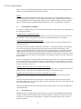
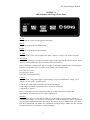
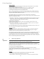
F3 SERIES
CASE SIZE 3A
FILTERED BATTERY CHARGER
OPERATION & MAINTENANCE
MANUAL
SENS part no.:
Document revision:
DCN number
Date
101146
H
106651
9/19/2014
1840 Industrial Circle
Longmont, CO 80501
Fax: (303) 678-7504
Tel: (303) 678-7500
Email: [email protected]
Web: www.sens-usa.com
Installation or Service problems? Call SENS at (800) 742-2326 between 8:00
am and 5:00 pm Mountain time Monday through Friday, or visit our website.
Copyright © Stored Energy Systems LLC 2006-2014
F3 Series Charger Manual
IMPORTANT SAFETY INSTRUCTIONS
SAVE THESE INSTRUCTIONS
This manual contains important safety and operating instructions for Stored Energy Systems (SENS)
model F3.
Before using the battery charger, read all instructions and cautionary markings on the battery charger,
battery and equipment connected to the battery system.
WARNING:
Please read
these safety
warnings and
heed them.
Failure to do so
could result in
either severe
personal injury
or equipment
damage.
This equipment uses and generates potentially lethal voltages. The equipment should only be installed and
maintained by trained persons. Do not attempt to install or operate this equipment unless you are certain
you are adequately trained.
To reduce the risk of injury, charge only properly sized lead-acid or nickel cadmium batteries. Other types
of batteries or under-sized batteries may burst causing personal injury and damage.
• Do not install or operate charger if it has been dropped or otherwise damaged. Return it to the factory
for repair.
• Install the charger in accordance with all local codes.
• Do not expose charger to rain or snow.
• Do not disassemble charger; return to factory when service or repair is required. Incorrect assembly may
result in a risk of electric shock or fire.
• To reduce risk of electric shock, de-energize and disconnect the AC input and the battery from the
charger before attempting maintenance or cleaning.
• Use of an accessory not recommended or sold by SENS may result in a risk of fire, electric shock or
personal injury.
• During normal operation, batteries may produce explosive hydrogen gas. Never smoke, use an open
flame, or create sparks near the battery or charger.
• Remove jewelry, watches, rings, etc. before installing battery or charger.
Maintenance
Instructions
User maintenance is limited to charger adjustment. All on-site servicing should be performed by qualified
service personnel. If qualified personnel are not available, return the charger to the factory for repair, or
contact the factory to arrange for field service.
When returning a unit to the factory for repair, ship it in the original factory packaging if possible. If the
original carton is not available, pack in a carton with at least 2 inches of approved packaging material on
all sides of the charger to help prevent shipping damage.
2
F3 Series Charger Manual
1
This manual covers installation, operation and troubleshooting of SENS model F3 filtered battery charger.
Overview
1.1
READ THIS FIRST
Please follow the installation and use instructions. They are vital to the satisfactory operation of the
charger. If you have any doubts about adjusting, maintaining or servicing the equipment, contact SENS
service department.
Changing factory-set potentiometers voids the warranty. Contact the factory if you believe that the
settings on your charger are incorrect.Before determining that the charger is not working correctly, check
the following:
1. Are three phases of AC power available to the charger?
2. Are any circuit breakers tripped or fuses blown?
3. Is the charger connected to a battery of the correct voltage?
4. Was the charger damaged in transit or installation?
5. The charger may have shut down to excessive output voltage. To ensure that the high volt shutdown
has been reset, turn off both the AC input breaker and DC output breaker for five minutes. This is
more than sufficient time for the DC voltage to decay and reset the shutdown.
6. If the battery is being over- or undercharged, check whether the output voltage settings have been
tampered with. The pots should be covered with either white adhesive paper dots or a hard colored
varnish. Under no circumstances change the adjustment of control board pots other than R33 and
R34.
1.1
Description and Application
The F3 is a fully automatic battery charger and DC current source offering the following features:
• Constant voltage output
• Electronic current limiting
• Filtered output (on battery rated in AH four times amp rating of charger): 12, 24, 48V: 30 mV rms; 110,
120V: 150 mV rms; 144, 240V: 300 mV rms
• Filtered output without battery: 12, 24, 48V: 100 mV rms
• With optional filter for 110 & 120V models: 30mV rms on battery, 300mV without battery
• Temperature compensation to maximize battery performance and life
• Circuit breakers for AC input and DC output
The chargers are designed to supply equipment requiring a low ripple DC source and to automatically
recharge and maintain a parallel connected lead-acid or nickel-cadmium battery.
1.2
Upon Delivery
Inspect the charger for damage caused during transit, and report damage to the carrier immediately. Then
contact SENS to determine how best to repair/replace the damaged unit.
3
F3 Series Charger Manual
2
2.1
Mechanical Installation
Installation
Caution: Heed the following warning to prevent damaging the lower cover of the charger!
FIGURE 2.1
Lifting Instructions
WHEN INSTALLING
DO NOT LIFT UNIT
FROM MIDDLE OF
LOWER COVER - THE
COVER WILL BEND.
USE A SPREADER
PLATE EQUIVALENT TO
1" THICK PLYWOOD
ACROSS THE BOTTOM
OF THE UNIT WHEN
LIFTING
The charger can be mounted either on a wall or in a standard 23” relay rack. Locate the charger in a dry
place as close to the battery and load as possible to minimize voltage drop.
WARNING: These chargers are not approved for operation in mines or other places with explosive
atmospheres
Wall Mounting
Mount the system to a robust wall using 1/4” bolts with flat washers behind the mounting holes if
necessary to level the charger on an uneven wall. The charger should be located as close to the battery
and load as possible to reduce voltage drop in the charging leads. Refer to the mechanical drawings at the
end of this document for case dimensions and mounting dimensions.
Relay Rack Mounting
The charger is shipped on its back with the mounting flanges in the wall-mount position. Place the
charger in a vertical position, then unbolt and reverse the mounting flanges. CAUTION: When changing
the angles from wall mount (the standard shipping configuration) to rack mount, you MUST either stand
the charger up vertically, or otherwise remove the charger’s weight from the rack angles when removing
the rack angle bolts. If you do not, the bolts in heavy chargers may strip on their way out.
Protect the charger from construction grit, metal chips, paint or other debris. Clean away debris after
installation and before turning on the charger.
Ventilation
The charger is designed to be convection cooled. Required clearances around the unit for proper cooling
are 6 inches on the top and 4 inches on the bottom.
2.2
Electrical - Power Wiring
WARNING: Heat sinks and many other metallic components inside the charger are LIVE with either line
or output voltage. These voltages can be lethal. Do not touch any exposed metal surfaces inside the
enclosure while the charger is operating.
Remove the two 1/4-turn fasteners securing the charger's top front panel and open the front panel. Make
4
F3 Series Charger Manual
AC and DC connections direct to the AC and DC circuit breakers in accordance with diagram 2.2 below.
Caution: Small sense leads are connected to the output side of the DC breaker. These must remain
connected to the output side of the breaker after installation of the DC cabling, or the charger will not
function properly.
FIGURE 2.2
Power Connections
AC INPUT
DC OUTPUT
ØA
ØB
ØC
+
Connection should be made by a qualified installer in accordance with national and local electrical codes.
The installer should determine the gauge of wire to be used based on the length of cable run and the
ampere requirements of the charger. Size the DC cabling to keep voltage drop in the charging leads as
low as possible.
Refer to TABLE 2.2 for the charger’s AC requirement of your charger. The input voltage and frequency
are marked on the charger’s front panel. Maximum current consumption will be approximately 75% to
80% of the breaker’s rating. Typical efficiency is 85% for 24 volt units, 88% for 48 volt units and 91%+
for 120 and 240 volt units. Power factor is approximately 0.8 at rated input voltage.
WARNING: The battery charger must be connected to a grounded permanent wiring system. A ground
stud or terminal is provided for this purpose
TABLE 2.2
AC Input Circuit Breaker Ratings
Charger output
V
24
24
24
A
100
150
200
V
48
48
48
48
48
A
50
75
100
150
200
Rated Charger AC Circuit Breaker (/Phase)
V
120
120
120
120
120
168
96
110
144
A
25
35
50
75
100
30
50
100
30
5
208V
amps
15
20
30
40
60
20
25
35
50
70
240V
amps
15
20
25
35
50
15
25
35
50
70
380V
amps
15
15
15
25
30
15
15
20
30
40
40
400V
amps
15
15
15
25
30
15
15
20
30
35
415V
amps
15
15
15
20
30
15
15
20
25
35
480V
amps
15
15
15
20
25
15
15
15
25
30
15
20
15
F3 Series Charger Manual
Caution: Do NOT connect the battery backwards; charger damage may result
The voltmeter will show battery voltage as soon as the DC connection is completed. Check the voltmeter
as soon as the DC connection has been made. If the meter reads zero or is deflecting below zero, reverse
the polarity of the battery connections.
2.3
Alarm Connections
F3 chargers are supplied with one of three following alarms configurations:
TABLE 2.3
Charger Part Number Suffix and Alarms Configuration
Second digit of part number suffix (e.g. "F5E2")
Alarms “0”
Alarms “5”
none
none
none
none
none
none
none
none
none
Alarms “6”
Float or boost mode
AC fail
Charger fail
Low battery voltage
High battery voltage
none
none
none
Summary of above
< Alarm system code
Indications
LED
LED & Form C contact
LED & Form C contact
LED & Form C contact
LED & Form C contact
LED
LED
Form C contact
Form C contact
Float or boost mode
AC fail
Charger fail
Low battery voltage
High battery voltage
Ground fault
Ground fault Ground fault + or Summary of above
Connect to the charger’s Form C contacts according to Figure 2.3
1. Make connections to the system's Form C alarm contacts as shown.
2. Run alarm wiring out of the charger separately from the AC supply wiring
3. Use 16 to 22-gauge wire.
4. NOTE: Do not exceed the relay maximum current rating of 0.5A @ 117 VAC or 1A @ 24 VDC.
The remote alarm connection board is located on the circuit breaker pan, adjacent to the control board.
See Figure 2.3 on next page.
FIGURE 2.3
Remote Contact Terminal Block
FAIL
OK
COM
AC
FAIL
FAIL
OK
CHARGE
FAIL
COM
FAIL
OK
LOW DC
VOLTS
COM
FAIL
OK
HIGH DC
VOLTS
COM
FAIL
OK
LOW DC
DISC.
COM
FAIL
OK
OPTION
COM
FAIL
OK
FAIL
2.4
COM
OK
COM
SUMMARY
GROUND
FAULT
Temperature Compensation
F3 chargers include battery temperature compensation (TC). TC is required by all batteries for maximum
performance and life. The TC feature automatically reduces the charger’s output voltage at high
temperatures and vice-versa.
6
F3 Series Charger Manual
The F3 has provision for either local or remote sensing of temperature. Local sensing is done by
components located on the charger’s control board, which is exposed to the ambient air. At installations
where the battery is located in a different room, or is otherwise subject to ambient temperatures different
from the charger it is necessary to sense temperature at the battery. The SENS remote sensor is optional.
The control board automatically selects the remote sensor over the local sensor. If the remote sensor is
damaged or disconnected temperature sensing automatically reverts to local.
The two leads of the RTS are connected to a port on the control board as follows: Connect the yellow lead
of the sensor to J6 “K” and the violet lead to J6 “A”. If the sensor is connected properly D12 will not
illuminate when the charger is in operation. If D12 stays lit, check that RTS leads are not reversed, and
check that the RTS is not damaged. Any excess length of the RTS leads should be cut off rather than
coiled, to ensure the shortest possible length. The RTS leads should be routed separately and away from
all other AC power, DC power, and alarm wires and cables to prevent noise coupling that may cause
abnormal operation of the charger.
NOTE: D12 on the control board will remain lit whenever the remote temperature sensor is either not
used, or if the remote sensor is disabled. This is normal when RTS is not used.
3
3.1
Start-up
Operation
Start with both input and output breakers OFF.
First, check that the connected battery voltage is correct (e.g. 120 volts for a 120 volt charger). It is OK if
the battery voltage is different from the nominal value by a few percent. If the battery voltage is more
than 10% different from the rated voltage of the charger, recheck your connections BEFORE turning on
either breaker.
Caution: To prevent damage to the charger, ensure the charger is connected to the battery and the load
(not solely the load) prior to closing the DC breaker. The battery should be approximately 3 to 4 times
the charger output current rating (e.g. 100 Amp charger needs 300-400Ah battery bank).
Next close the AC input breaker. Check that the charger voltage comes up to approximately nominal.
(Some voltage overshoot on initial startup is normal).
Next close the DC output breaker. The charger will immediately begin to supply current if required by the
battery or load.
In chargers with alarms code “5” or “6”, the front panel AC FAIL and CHARGE FAIL lights will
extinguish, and should be replaced by the green AC ON light.
The charger will automatically supply power to the load and maintain the battery without further attention.
If the charger does not start as described, or appears to have failed, check the following:
• Verify that AC mains power is available
• Verify that no external circuit breakers are tripped
• Verify that contractor-installed AC, DC and alarm connections are correct
• Disconnect AC and DC power sources. Open the charger. Verify that no components (e.g. main DC
output fuse, if fitted) or harness connections are blown, loose or damaged
If all of the above appear to be in order, contact SENS at the toll-free service number on the front of this
document for assistance in troubleshooting.
3.2
FLOAT/BOOST MODES
Two modes of voltage control are provided in all F3 chargers as follows:
FLOAT
The float mode is the battery “maintenance” voltage. It is the normally fully charged voltage of the
7
F3 Series Charger Manual
battery. This is the normal charging position for all batteries, and the recommended charging position at
all times for Valve Regulated Lead Acid (VRLA) batteries.
BOOST
This voltage is slightly higher than the float setting. Boost slightly overcharges the battery in order to
ensure that all the cells of a battery are fully charged to the same voltage. Continued operation in boost is
not recommended because the high charging voltage will cause battery electrolyte to boil away quickly.
This is a particular problem with VRLA batteries where there is no way to replenish lost electrolyte.
3.3
FLOAT/BOOST CONTROL
F3 chargers are equipped with one of the four following float/boost voltage control systems depending on
the configuration ordered:
FLOAT/BOOST front panel rotary switch
The charger will operate indefinitely in the mode that is selected. The AUTO position may be shown on
the front panel. If the AUTO position is locked out, the AUTOBOOST feature is not supplied.
AUTO/FLOAT/BOOST front panel rotary switch
When the selector switch is in the FLOAT or BOOST mode the charger will operate indefinitely in the
mode that is selected.
The AUTO mode selects automatic equalization of the battery. The charger determines when the battery
is in need of fast charging, and operates in the fast charge boost mode only until the battery is fully
charged. The charger determines state of charge by the measuring the amount of current drawn from the
output terminals. When the selector switch is in the AUTO position the charger will start in the boost
mode and stay there until current demanded drops below about 50% of the charger’s rated current. When
current demand increases to about 70% of the charger’s rated output the charger will resume operation in
the boost mode.
Please see the Appendix for a diagram of how the Autoboost system works. The AUTO setting eliminates
the need to periodically equalize the cells of a battery as the charger does this automatically. The AUTO
position should not be selected when the continuous load on the charger is greater than about 50% of the
charger’s maximum rated current.
Manually initiated boost timer (either 0-24 hours or 0-72 hours)
When the timer is turned clockwise the charger will be in boost mode, where it will remain until the timer
returns to 0 hours. At the end of the selected time the charger will return to float mode.
Manually initiated boost timer plus AUTO/FLOAT/BOOST rotary switch
Selection of the AUTO position allows the charger to operate in the AUTOBOOST mode (described
above)
Selection of the FLOAT mode forces the charger to remain in the float mode unless the boost timer is
activated by turning past zero. If the boost timer is activated, the charger will revert to float mode after the
time selected on the timer expires.
Selection of the BOOST mode forces the charger into boost charge, where it will remain until BOOST is
deselected manually.
3.4
Alarm Indications
NOTE: Chargers are equipped with a “dead-front” panel. Alarm LEDs are behind the dead front panel
and will be visible when they illuminate due to an alarm condition, or when the TEST button is pressed.
See Figure 3.5 for the location of LED indicators. Chargers with no alarms (alarms code “0”) have no
LEDs or test button.
8
F3 Series Charger Manual
FIGURE 3.4
LED Indicators on Charger Front Panel
AC ON
Indicates that AC power is being supplied to the charger.
BOOST
The charger is operating in the BOOST mode.
FLOAT
The charger is operating in the FLOAT mode.
AC FAIL
Indicates that AC power is not available to the charger. Input AC is failed, or AC breaker is tripped.
CHGR FAIL
Indicates that the charger is failing to produce the output current required by the battery and load. When
the battery and load demand no current the failure alarm will not activate.
In the event that the CHARGE FAIL and AC ON lights are illuminated simultaneously, then the charger
has failed. The probable causes of an alarm, in descending order of likelihood are:
a) A failure of AC power
b) A tripped AC breaker
c) The charger has malfunctioned
LOW DC
Indicates that DC voltage has dropped to approximately 8.5% below nominal battery voltage (e.g. 22
volts for a 24 volt system). Probable causes:
a) The AC power has failed, and the battery has become discharged
b) The charger has malfunctioned and the battery has become discharged
c) The battery is defective
There is a time delay in the low voltage alarm which prevents the alarm from activating until
approximately 30 seconds after the low voltage condition starts.
HIGH DC
Indicates that the charger’s output has exceeded a pre-set threshold level (approximately 20% above
nominal battery voltage - e.g. 29 volts for a 24 volt system). If this alarm stays activated for any period of
time, the charger should be shut down and serviced. The charger may have malfunctioned, or the alarm
card may be misadjusted. The alarm actives immediately upon high voltage condition, but stays activated
for approximately 30 seconds after the condition disappears.
9
F3 Series Charger Manual
HIGH DC SHTDN
Indicates that the charger has been shut down by the high output voltage shutdown circuit. Probable
causes of a high DC shutdown are as follows:
a) The float or boost voltages have been increased above the pre-set shutdown voltage
b) The high voltage shutdown set point has been changed from the factory setting.
c) The charger has malfunctioned, and is not regulating properly.
There is a delay of approximately 5 seconds after the onset of the high voltage condition until the unit
shuts down. When a high volt shutdown occurs, the red HVS LED on the control board will illuminate,
along with the SHUTDOWN LED on the front panel.
If the high DC shutdown activates the charger will stay off until the battery voltage drops to
approximately nominal, at which point the circuit will reset and the charger will start. Manual reset of the
shutdown is accomplished as follows:
1) Turn off the AC input breaker. (Note that while the SHUTDOWN LED will extinguish, the charger is
still locked out. This is because the shutdown LED is driven by the control board's power supply,
which is derived from the AC supply, rather than from battery).
2) Turn off the DC output breaker.
3) Wait for about one minute for capacitor voltage to decay through the capacitor bleeder resistor
4) Turn on the DC output breaker
5) Turn on the AC input breaker. If the charger is still in high DC shutdown, repeat steps 1 through 3,
waiting longer before turning DC and AC breakers back on.
The control board includes two sets of Form C contacts for high volt shutdown indication. Either one of
these can be used for remote indication of high voltage shutdown.
GROUND (optional)
This is a ground fault alarm. If either the charger’s positive or negative is connected to ground, even
through a high resistance path, this alarm will activate. LEDs indicate either positive or negative
grounding. The Form C contact only indicates that a fault has occurred.
Some applications require that ground be referenced to either the positive or negative output. In this case,
the activated ground fault alarm will be a nuisance. The alarm can be safely disabled by placing the
ground fault jumper located on the alarm board (mounted on the charger’s front door) in the “disabled”
position. When pins 1 and 2 of J5 are connected together the ground fault alarm is disabled. When pins 2
and 3 are connected the ground fault alarm is enabled.
4
4.1
Output Voltage Adjustment
Adjustments
WARNING: Working inside the charger exposes you to dangerous AC and DC voltages. Do not touch
circuit breakers, filter capacitors, heat sinks or any other exposed metal surfaces
NOTE: Do not tamper with factory adjustments unless sure adjustment is necessary. Temperaturecompensated control circuitry automatically adjusts the output voltage depending on temperature. Adjust
the output only under these circumstances:
a) To correct a previous unauthorized adjustment
b) To adjust the charger for a different type of battery (e.g. from lead-acid to nickel-cadmium)
c) If your battery is consistently being over-charged or under-charged
NOTE: Unless authorized by SENS, any charger adjustment, including output voltage adjustment, voids
the warranty.
Procedure
1. Use a precision external voltmeter connected directly to the charger output terminals.
2. Set the charger’s front panel FLOAT/BOOST control to FLOAT.
3. Open the charger’s front panel and locate the control card. It contains two potentiometers labeled
10
F3 Series Charger Manual
“FLOAT” (R34) and “BOOST” (R33), both located next to one of the control transformers.
4. Adjust the FLOAT pot until the desired voltage is achieved.
Adjustment of the BOOST voltage is similar to adjustment of FLOAT, except that you adjust the BOOST
pot instead of the FLOAT pot. Be sure that the charger front panel mode switch is in BOOST when you
make adjustments.
Please note that the BOOST adjustment controls the level above FLOAT voltage, not the absolute
voltage. Therefore, whenever the FLOAT the voltage is changed, the BOOST voltage also changes.
4.2
Factory-Set Output and Alarm Voltages
NOTE: Output voltages are temperature compensated (vary with temperature). The factory settings
below are at 20 degrees C. The compensation is -0.18% per degree C. The alarm voltage settings are
NOT temperature compensated.
Chargers set for sealed maintenance-free lead-acid battery
12 volt
24 volt
32 volt
48 volt
120 volt 168 volts 240 volt
Float voltage
13.62
27.24
36.32
54.48
136.20
190.68
272.40
Boost voltage
13.80
27.60
36.80
55.20
138.00
193.20
276.00
Low DC alarm
11.00
22.00
29.33
44.00
110.00
154.00
220.00
High DC alarm
14.61
29.22
38.96
58.44
146.10
204.54
292.21
High DC shutdown
15.19
30.39
40.52
60.78
151.95
212.73
303.89
Chargers set for flooded lead-acid battery
12 volt
24 volt
Float voltage
13.32
26.64
Boost voltage
14.00
28.00
Low DC alarm
11.00
22.00
High DC alarm
14.82
29.64
High DC shutdown
15.41
30.83
32 volt
35.52
37.28
29.33
39.47
41.05
48 volt
53.28
55.92
44.00
59.20
61.57
120 volt
133.20
139.80
110.00
148.01
153.93
168 volts
186.48
196.00
154.00
207.48
215.50
240 volt
266.40
279.60
220.00
296.02
307.86
Chargers set for nickel cadmium battery
Multiply volts per cell times # of cells for actual voltage
Per Cell
Float voltage
1.43
Boost voltage
1.52
Low DC alarm
1.19
High DC alarm
1.61
High DC shutdown
1.67
Chart 4.2 shows relationships between charger output voltage, alarms and high volt shutdown. Output
voltage is temperature compensated down to ten degrees C; compensation then ends.
To determine the charger’s voltage at temperatures other than 20 deg. C., multiply number of degrees C
difference between ambient and twenty C times .0018. Multiply that product times the factory voltage
setting (e.g. 27.24) and add it to the factory setting. Examples:
Example 1: Float voltage at 10 degrees C of a 24 volt charger set for 27.24 volts at 20 degrees C:
20-10 (.0018) (27.24) + 27.24 = 27.73 volts
Example 2: Float voltage at 50 degrees C of a 24 volt charger set for 27.24 volts at 20 degrees C:
20-50 (.0018) (27.24) + 27.24 = 25.77 volts
11
F3 Series Charger Manual
CHART 4.2
Graph of Factory-Set Output, Alarm and Shutdown Voltages
2.55
VRLA Float
2.45
VRLA Boost
Flooded Float
2.35
Flooded Boost
2.25
HV Alm VRLA
2.15
HV Shtdn VRLA
1.85
HV Alm Flooded
1.75
HV Shtdn Flooded
Low DC Alarm
Degrees C
4.3
Forced Load Sharing
Chargers can be set up for forced load sharing when used in parallel with units of the same current
rating. Forced load sharing causes the chargers to share the load from light loading to full load except
when either charger is in BOOST mode (whether activated manually or via the AUTO BOOST
system) or if either charger is operating in current limit. Chargers will share the load within +10% of
each other.
To set up, ensure that the DC output leads from each charger are identical in length and wire gauge.
Install a Load Share Cable (supplied by SENS or assembled by user) between terminals on both
control boards where labeled “PAR”.
To assemble a Load Share Cable:
1. Cut desired length of single wire (18 or 22 wire AWG).
2. Connect a 10KΩ, 2 Watts or more, resistor inline with signal wire. Connect resistor to wire
using a Butt Connector or twist wires together and cover with Heat - shrink.
12
F3 Series Charger Manual
5
5.1
Troubleshooting Table
Troubleshooting
If there is a problem and you suspect the charger is at fault, turn off the AC mains supply before
proceeding. Ensure that the following are correct: AC input wiring, battery and/or load connections
and PC card connectors. Ensure no foreign objects are in charger.
Symptom
No output /
Charge Fail
alarm
Possible Cause
Control board
failure
Test
Replace with known good
board
DC Fuse blown
High DC Shutdown
Check fuse for continuity
Check LED D30 on control
board
Power rectifier
circuit failure
AC failure
Shutdown due to
excessive output
voltage
AC breaker Power diode, SCR,
or freewheeling
trips
diode short
repeatedly
Control board
DC fuse blows
failure
or DC
breaker trips
Freewheeling diode
short
Control board
Low output
failure
voltage / Low
DC alarm
Misadjusted Float
Voltage pot (R34)
on control board
Overloaded charger
Corrective Action
Replace board,
Replace if open
If lit, see "High output
Voltage" under Symptom
below in this chart
Test all power diodes with
Replace all shorted, open, or
meter, perform SCR test on all
bad parts
SCRs (figure 5.2)
Check input supply
Restore AC input supply
Check whether LED D30 on Shut off AC and DC breakers
control board is lit
for at least 2 minutes, then
restore
Check all power devices for
Replace shorted device(s)
shorts
Replace with known good
board
Replace board, send bad
board to SENS for repair
Check diode for short
Replace diode
Replace with known good
board
Replace board,
Adjust pot and see if output
voltage is affected
Adjust R34 to correct output
voltage
Turn off DC breaker, check Check load for problems, and
voltage on INSIDE breaker
check battery condition
terminals
Overheating
Test all power diodes and
Replace bad devices
SCRs (figure 5.2)
Check for obstruction of top
Remove obstruction(s)
and bottom vents
Check for vertical mounting of
Mount charger vertically
charger
Verity that room temperature
Reduce room temperature
is less than 50 C
Verity that AC input voltage
Contact utility company
is not higher than charger's
specified operating range
Check for failure of one phase Contact electrician or utility
company
Bad filter capacitor Disconnect capacitors one at a
Replace capacitor that
time and check for change in
corrected output voltage
output voltage
when removed
13
F3 Series Charger Manual
Symptom
High output
volts / High
DC alarm
Possible Cause
Test
Corrective Action
Line voltage less
that charger's
specified operating
range
Control board
failure
Measure AC line voltage
Use larger gauge AC wires or
contact utility company
Replace with known good
board
Replace board
Adjust pot and see if output
voltage is affected
Adjust float pot to correct
output voltage
Misadjusted Float
Voltage pot on
control board
Remote temperature
sensor failure
Remove Remote Temp.
Replace Remote Temp.
Sensor connector on control
Sensor
board J6
Control board
Replace with known good
Replace board,
High ripple
failure
board
voltage
Excessive line
Measure and compare the
Contact electrician or utility
voltage imbalance
three AC phase voltages
company
Power diode / SCR
Test all power diodes with
Replace all open or bad parts
failure
meter, perform SCR test on all
SCRs (figure 5.2)
AC phase failure
Check for failure of one phase Contact electrician or utility
company
AC line voltage too
Check for AC line voltage
Contact utility company
high
over charger's specified
operating range
Bad filter capacitor Disconnect capacitors one at a
Replace capacitor that
time and check for change in
corrected output voltage
output voltage
when removed
Alarm, display, or
Replace each board in turn
Replace failed board(s)
Alarms or
with a known good board
indicators not control board failure
functioning
5.2 Component Diagnostic Tests
Test #1: With transformer leads disconnected, energize the transformer with the normal AC supply
voltage. Measure entire secondary voltage. It should be 1.1 times the nominal battery voltage.
Test #2: With one or both leads disconnected from the inductor, measure the resistance across the
inductor terminals. If the resistance is near a short circuit condition, the inductor is OK.
Test #3: Power Diodes, units with SCR/diode modules
See the attached SCR/diode module troubleshooting table to determine module condition.
Test #3: Power Diodes, units with stud-mount diodes
Using a digital multimeter set to the diode testing function, measure the junction voltage across the
diode. A reading of between 0.4 volt and 0.8 volt in the forward polarity direction and infinity in the
reverse polarity direction indicates a good diode.
Test #4: SCRs, units with SCR/diode modules
See the attached SCR/diode module troubleshooting table to determine module condition.
Test #3: SCRs, units with stud-mount SCRs
14
F3 Series Charger Manual
Refer to Figure 5.2. Disconnect all the leads to the SCR and its heat sink. Connect a voltmeter across
the 1KΩ resistor to measure the voltage drop. With the battery connected as shown, Vdrop should
read approximately 2.3V (Vsource-0.7V). Remove the voltage source to the gate, but keep it
connected to the 1KΩ resistor and cathode. Vdrop should equal zero. Reconnect the gate and reverse
the batteries polarity. Vdrop should read zero volts. Readings other than these indicate a defective
SCR.
Test #5: Due to the modest cost of the control circuit, we recommend that the entire unit be replaced
rather than attempting to repair it. If the troubleshooting guide has not revealed any defective
components (tests #1-4), the control circuit should be replaced as a unit.
Test #6: Remove all wires from the current shunt. Place a milliohmmeter across the two terminals.
The following formula should be used to determine the correct resistance:
Resistance in ohms should equal 0.5/Output current rating of the charger, except in 35 amp units when
resistance should equal 0.1 ohms.
If the resistance is more than 20% too low, the current shunt should be replaced.
FIGURE 5.2
SCR test setup
15
F3 Series Charger Manual
16
F3 Series Charger Manual
Diagram of Automatic Boost Operation (Optional Feature)
Appendix
Boost v oltage
Float v oltage
Battery voltage
Point at which charger changes
f rom current limit to v oltage limit
Volts
Point at which AUTOBOOST
returns charger to f loat v oltage
100% charger
output current
Charger output current
Amps
50% to 75% of
charger current limit
Zero current f low
0
Time
NOTE:
When the charger switches f rom BOOST to FLOAT mode,
no current will f low into the battery f or a while due to the battery 's
high state of charge.This is completely normal, and indicates
that the charger is working properly.
17
SENS Limited Warranty Policy
What is covered:
This warranty covers any defect in material and workmanship on battery chargers manufactured
by Stored Energy Systems, a Colorado Limited
Liability Company (SENS).
What this warranty does not cover:
This warranty does not cover damages, defects or failures of your equipment resulting from
shipping damage, accidents, installation errors, unauthorized adjustment or repair, unauthorized
third-party service, failure to follow instructions, misuse, fire, flood, acts of persons not in our
control, and acts of God.
For how long:
Two years from date of shipment.
What we will do:
If your battery charger is defective within two years of date of shipment, we will repair it or, at
our option, replace it at no charge to you.
If we choose to replace your charger, we may replace it with a new or refurbished one of the
same or similar design. The repair or replacement will be warranted for the remainder of the
original two-year warranty period. If we determine that your charger cannot be repaired or
replaced, we will refund its purchase price to you.
What we ask you to do:
First contact SENS service department to obtain warranty service
instructions. To obtain
warranty service the product must be returned, freight prepaid, to the factory under a Return
Merchandise Authorization
(RMA) number provided by SENS. If, in SENS’ opinion, the
problem can be rectified in the field, SENS may elect to ship replacement parts for customer
installation instead of having the product returned to the factory.
Limitation:
This warranty is limited to defects in material or workmanship of the product. It does not cover
loss of time, inconvenience, property damage or any consequential damages. Repair,
replacement or refund of the purchase price of the equipment is your exclusive remedy.
Form.135-1