1
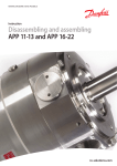
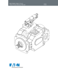
MODEL #NMP 830KT
POINTS OF INTEREST:
•
•
•
•
•
•
The pump must not start against pressure or vacuum. When it is switched on,
the pressure in the suction and pressure lines must be atmospheric
The maximum permissible operating pressure (see type plate or data sheet)
must not be exceeded. EXCEPTION: If the data sheet includes valves for
intermittent operation, they may be employed briefly.
To prevent the maximum permissible operating pressure being exceeded,
restriction or control of the air or gas flow should only be carried out in the
suction line.
If restriction or control of the air or gas flow is made on the pressure side,
ensure that the maximum permissible operating pressure is not exceeded.
When the pump is at a standstill the inlet and exhaust must be at normal
atmospheric pressure.
Diaphragm and valve plate(s) are the only parts subject to wear. Wear is
usually indicated by a drastic reduction in the pneumatic performance. When
replacing parts proceed as described in section 4
SECTION 4:
SERVICING:
•
Before working on the pump isolate the power supply securely,
then check that the lines are not live
Always change valve plate(s), diaphragm, and O-rings (if existing)
at the same time.
•
CHANGING THE DIAPHRAGM
PARTS REQUIRED
NMP 830 KT: CAI Part # 310309-4
•
•
•
1 Diaphragm
2 Valve Plates
2 O-rings
TOOLS REQUIRED:
•
•
Phillips screwdriver #1
Pencil
CHANGING THE DIAPHRAGM
PROCEDURE:
1. Mark the position of head parts relative to each other by drawing a line
with a pencil. This helps to avoid incorrect assembly later
2. Undo the four screws c in the head
3. Lift the head plate fand the intermediate plate i complete with valve
plates g and O-rings h off the housing
4. Hold the pump with one hand, so that the diaphragm is pointing
downwards. Lift the diaphragm j by the opposing side edges, grasp it and
unscrew it in the counter-clockwise direction.
5. Take the diaphragm spacers k off the threaded portion of the diaphragm
and put them on the threaded portion of the new diaphragm.
6. Move the connecting rod to the upper point.
7. Screw the new diaphragm j with spacers k clockwise onto the
connection rod and tighten hand tight.
8. place the intermediate plate i on the housing, in the position indicated by
the drawing line.
9. Exchange both valve plates g and both O-rings h. The valve plates for
pressure and suction sides are identical, as are upper and lower sides of the
plates.
10. Place the head plate f on the intermediate plate i, in the position
indicated by the drawing line; gently tighten the four screws c (with
spring washer d and washer e) evenly and diagonally (if a torque
screwdriver is available: torque about 0.30 Nm)
11. Let the pump run.
NMP 830KT
1
2
3
1
Screw
2
Spring Washer
3
Washer
4
Head Plate
5
Valve Plate
6
O-ring
7
Intermediate Plate
8
Diaphragm
9
Spacer
4
5
6
7
8
9
Connecting Rod
NMP 830 Pump Diaphragm 5/08
SPARE PARTS KITS
ELASTOMER REPLACEMENT KIT:
For Models N010AT.11l, N010ST.11l, N010AT.16l, N010ST.16l
Kit Part # 071708
QTY
ID#
DESCRIPTION
1
E
Teflon valve plate
2
H
Teflon diaphragm
HEAD PARTS REPLACEMENT KITS:
For Model N010ST.11l
Kit Part #200182
ID#
QTY
1
A
1
B
1
F
1
G
2
M
1
M
2
M
1
N
DESCRIPTION
Head plate
Intermediate plate
Flathead screw
Clamping disk
Panhead screws
Thermo switch
Washers
Heating element
For Model N010AT.16l
Kit Part #200183
For Model N010ST.16l
Kit Part #071714
QTY
1
1
1
1
ID#
A
B
F
G
DESCRIPTION
Head plate
Intermediate plate
Flathead screw
Clamping disk
Note: If your model number begins with MPU, PU or PJ, contact KNF Customer Service
for the proper Parts Kit, as the contents may differ from those listed above.
CHANGING THE DIAPHRAGM AND VALVE PLATE
During Normal use, the diaphragm and valve plate are the only parts of the
pump that need to be replaced. If you run into a problem or have a question
regarding the following procedure, please call KNF Applications Engineering for
assistance.
MATERIALS/TOOLS NEEDED:
The proper replacement kit
Marking pencil
7mm Nut driver
Slotted-head screwdriver
PROCEDURE:
SHUT OFF ALL POWER and UNPLUG POWER CORD
1. It is usually not necessary to remove the heated-head (.11) wiring.
2. Mark the relative positions of the head plate A intermediate plate B and
mounting ring C with a line using a marker for ease or re-assembly later.
3. Undo the 4 head nuts & flat washers D, and 6 cup washers L from the studs
and lift off the head plate A, valve plate E and intermediate plate B.
4. Lightly clean the valve seat area of the head plate A and intermediate plate B,
if necessary, of any deposits with fine steel wool. This area must be clean and
smooth without pits or scratches to obtain best performance
5. Loosen the countersunk slotted-head clamping disc screw F and remove the
clamping disc G, the two diaphragms H, connecting rod disc and shim disks
P. Replace exact number of shims when reassembling.
6. Turn the motor fan or counterweight by hand until the connecting rod K is at
mid-stroke, and place the shim disk(s) P, the connection rod disc, two new
diaphragms H on the housing C, lining up screw holes. Brown side down (if
applicable).
7. Place the clamping disc G (bevel side up) on top of the two new diaphragms
H. Tighten the countersunk clamping disc screw F SNUGLY (but not too
tight)
8. Place the intermediate plate B over the diaphragm, lining up the marks made
previously in step 2.
9. Place the valve plate E on top of the intermediate plate B, orienting the valve
flaps with the holes. Brown side down (if applicable)
10. Place the head plate A on top of the valve plate E, Lining it up with the
markings you made in step 2.
CHANGING THE DIAPHRAGM AND VALVE PLATE
PROCEDURE: (continued)
11. Be sure that all components are centered. Position the 6 cup washers L over
each stud, oriented as shown in the diagram, then the flat washer. Tighten the
4 head nuts D in a crisscross pattern to a SNUG FIT. Do not over tighten.
Remove any old TEFLON tape from all fittings. Carefully apply two layers
of TEFLON tape around any fittings before reinstalling into pump head. Do
not apply tape beyond threads, as excess tape may tear off and lodge in the
valve. Do not substitute fro any other type of tape!
12. Check that the pump runs freely by turning the motor fan or counterweight J
by hand. Check all mechanical and electrical connections for tightness.
Replace the housing lid.
13. Apply power to the pump. Listen for a possible “knocking” sound. If it is
present, equally loosen the four head screws slightly until the sound just
disappears. This step is to be sure that the clamping disc does not touch the
intermediate plate during operation.
Notes: Should you need to send a KNF pump to our factory for repairs, please be sure to
read the instructions in the Limited Warranty section with regard to obtaining an RMA
(Return Materials Authorization) number prior to shipment.
FOR SERVICE OR PARTS CONTACT:
KNF NEUBERGER, INC.
Two Black Forest Road
Trenton, NJ, 08691-1810
(609) 890-8600 phone
(609) 890-8323 fax
http://www.knf.com
UN010KT
Head nut and single
flat washer
D
Headplate
A
Valveplate
E
Intermediate Plate
B
Spacer Ring
C
L
Six Cup Washers
(See Note)
N
Heating Element
(Heated Version Only)
F
Clamping Disk Screw
G
Clamping Disk
H
Two Diaphragms
NOTE:
Cup Washer
Orientation
Connecting Rod Disk
P
Connecting Rod
K
Counterweight
J
Figure A
Shim Disk(s)
(Reassemble with exact
number removed.)
A
Headplate
E
Valveplate
B
Intermediate Plate
CAUTION:
Be sure valve ports
and valve plate are
positioned as shown in
Figure A
(Large hole opposite
small hole).
UN010 Pump Diaphragm 5/08
400/600 CLD/HCLD
OZONE CAPILLARY CLEANING
SAFETY INSTRUCTIONS
• Before Working on Analyzer
– Remove Power Connections
• Proper Safety Procedures Must Be
Observed At All Times
If the analyzer has an oven
Using a Phillips screwdriver remove the six screws and set
cover aside
cover
Using a 7/16th wrench, loosen the fitting on the left side of
the measuring chamber and pull out the ozone capillary
You may need to use a back up wrench
fitting
Disconnect the ozone capillary from the tubing
ozone capillary
A second 7/16th wrench may be needed to hold the elbow
While disconnecting the ozone capillary a second 7/16
wrench may be needed to hold the elbow
ozone capillary
Check the capillary for damage and/or discoloration
mixing tube
capillary
Using high pressure air, blow out the tubing in both
directions to clean.
mixing tube
capillary
Reassemble in opposite steps
Make sure not to bend the mixing tube when inserting it into the
measuring chamber
400/600 CLD/HCLD
SAMPLE CAPILLARY CLEANING
SAFETY INSTRUCTIONS
• Before Working on Analyzer
– Remove Power Connections
• Proper Safety Procedures Must Be
Observed At All Times
If the analyzer has an oven
Using a Phillips screwdriver remove the six screws and set
cover aside
cover
Using a 7/16th wrench, loosen the fitting on the left side of
the measuring chamber and pull out the ozone capillary
You may need to use a back up wrench
fitting
Using the same 7/16th wrench, remove the pressure tap
You may need to use a back up wrench
pressure tap
Using 9/16th wrench, remove the outlet tube
You may need to use a back up wrench
outlet tube
Using 7/16th wrench, remove sample fitting
You may need to use a back up wrench or wedge screwdriver
sample fitting
Pull out the sample capillary from the measurement
chamber
sample capillary
Make sure not to bend the capillary
To free the sample capillary and tubing from the analyzer,
remove the fitting from the manifold
You may need to use a back up wrench
manifold
Using high pressure air, blow out the sample capillary in
both directions.
You may need to use a back up wrench
If unable to clean, replace the sample capillary and sample tube
Reassemble in opposite steps
400/600 CLD/HCLD
OZONE LAMP REPLACEMENT
SAFETY INSTRUCTIONS
• Before Working on Analyzer
– Remove Power Connections
• Proper Safety Procedures Must Be
Observed At All Times
Using 7/16th” wrench remove the outlet fitting
outlet fitting
Using 7/16th” wrench remove the inlet fitting
inlet fitting
Using a Phillips screwdriver, remove the saddle clamps (2)
saddle clamp #1
Using a Phillips screwdriver, remove the saddle clamps (2)
saddle clamp #2
On the power connector, squeeze the two locking tabs
together
power connector
While squeezing the two locking tabs together, separate
the connector
locking tabs
Lift out the lamp housing
lamp housing
With the lamp housing out, unscrew the black retaining ring
retaining ring
Gently remove the lamp from the housing
Because of oils on skin, do not touch lamp with bare hands
lamp
CAUTION—Do not break the lamp it contains MERCURY!
Reassemble lamp and housing in reverse order.
Because of oils on skin, do not touch lamp with bare hands
lamp
Make sure to align long tube with the inlet and outlet fittings
400/600 CLD/HCLD
MEASUREMENT CHAMBER
CLEANING
SAFETY INSTRUCTIONS
• Before Working on Analyzer
– Remove Power Connections
• Proper Safety Procedures Must Be
Observed At All Times
Using a 11/32” nut driver, remove the nuts securing the fan
housing
fan housing
Set fan and fan housing aside
fan housing
1. Remove the two power connectors from the detector board
NOTE: The connectors are keyed to ensure easy re-installation
connector #1
1. Remove the two power connectors from the detector board
NOTE: The connectors are keyed to ensure easy re-installation
connector #2
Using a 9/64th” Allen key remove the four cap screws
holding the black heat sink and detector board
cap screw
Maintain pressure against the housing while taking off the last cap screw
because the assembly is slightly spring loaded—(see picture next page)
Maintain pressure against housing while taking off the last
cap screw because the assembly is slightly spring loaded
housing
Gently rotate the detector assembly back exposing the
photo diode and ground strap
ground strap
photo diode
Using needle nose pliers remove ground strap
and set detector assembly aside
ground strap
torsion spring
Be sure not to lose the flat torsion spring on the detector diode housing
Using a 9/64th”Allen key remove two opposing cap screws
holding the filter ring
filter ring
The cap screws are slightly longer for the filter housing ring than the
detector housing
The cap screws are slightly longer for the filter housing ring
than the detector housing
longer cap screws
Insert two retaining studs. This prevents the measuring
chamber from disconnecting from the chamber mount.
retaining studs
Remove the remaining cap screws
cap screws
Gently remove the filter retaining ring and set aside
filter retaining ring
Remove the optical filter exposing the measuring chamber
measuring chamber
optical filter
Set optical filter aside for cleaning
measuring chamber
optical filter
Using Isopropyl alcohol (or soap and water)+ Q-Tips (or soft cloth)
thoroughly clean any deposits from the surface of the optical filter
optical filter
Clean reflective surface of the measuring chamber.
reflective surface
Take care not to damage the sample capillary in the center of the chamber
Reassemble all components in reverse order
Make sure to use the longer cap screws for the filter retaining ring