1
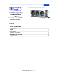
ANHYDRATOR INSTALLATION AND OPERATION
BULLETIN ANH-SB07b
SERVICE BULLETIN
VALVES • VESSELS • SYSTEMS • CONTROLS
System drawings shown in this bulletin are for illustration purposes only. Refrigeration systems should only be serviced by a qualified technician.
Always observe proper safety procedures when servicing a refrigeration system. For more information see the latest revision of Phillips Safety
Bulletin SGRV.
GENERAL INFORMATION
Pressure Rating:
300 psig (21 bar, gauge)
Approximate Weight:
Bare Unit: 375 lb (170 kg)
Unit with Valves: 450 lb (205 kg)
Heat Transfer Rate*:
6 Tons (21 kW) at 135°F (75°C) DT
collected in the Anhydrator ultimately becomes a mixture of
up to about 70% water, 30% ammonia, and other
impurities. (It is not practical to remove all the ammonia
from the water.) These impurities are drained from the
bottom of the unit and disposed of according to local
regulations.
PURE
AMMONIA TO
SUCTION
ACCUMULATOR
*The Anhydrator does not impose a heat load on the refrigeration system. The stated
Heat Transfer Rate is useful for estimating how quickly cold liquid vaporizes to separate impurities.
The Phillips Anhydrator operates as a self-regulating still to
remove water, oil, and other impurities from ammonia. Because
the unit uses heat from high pressure liquid, thereby subcooling
it, the unit is essentially energy-neutral. Because of its unique
self-regulating capability, the unit can be allowed to run
indefinitely without draining the accumulated impurities until a
time that is convenient for the operator. Installing the Anhydrator
as outlined in this bulletin will ensure low system operating costs
with minimal maintenance.
Inside the Anhydrator, cold impure liquid ammonia (typically
taken from the pump discharge) is exposed to heat from the high
pressure receiver liquid. (Refer to Figure 1.) The warm and cold
streams do not mix. The cold impure liquid ammonia boils, and
the resulting pure ammonia vapor is returned to the pump
accumulator. After giving up some of its heat, the liquid from the
high pressure receiver also goes to the pump accumulator.
Because this liquid is now subcooled, the reduction in flash gas
at the accumulator roughly balances with the pure ammonia
vapor mentioned earlier. Depending on the system, the liquid
AMMONIA &
CONTAMINANTS
FROM SUCTION
ACCUMULATOR
HP LIQUID SUPPLY
TO SYSTEM
LIQUID FROM
HP RECEIVER
WATER &
CONTAMINANTS
OUT
Figure 1: Flow through the Anhydrator
(Unit shown with 300HM Float Valve)
INSTALLATION
The Anhydrator should be located in an area with adequate
ventilation for safe draining, as described later in this bulletin. Also,
the HP liquid line should never include two isolation valves that
could trap the liquid inside the Anhydrator (figure 3). On systems
with liquid lines larger than 1", the Anhydrator may be supplied with
by-passed warm liquid in the manner shown in figure 4.
ANH-SB07b
DRY SUCTION
S
TO
EVAPORATORS
CONTAMINATED
LP LIQUID
SUB-COOLED HP LIQUID
Figure 2 is an example of how the Anhydrator may be integrated
into a basic liquid recirculation system. Here, a small amount of
contaminated liquid is taken intermittently from just downstream of
the pumps. The ammonia vaporized in the Anhydrator returns to the
accumulator, while the impurities are left behind. Although the
Anhydrator’s self-regulation prevents liquid from returning through
the vapor connection due to boil-over, attaching the vapor outlet to
the accumulator or a wet suction line provides an extra measure of
safety against a component malfunction.
WET SUCTION
PURE NH3 VAPOR
Inside an ammonia system, water travels with liquid ammonia and
accumulates in locations like pump accumulators and flooded
chillers. Connecting the Anhydrator to these locations allows water
and other contaminants to be safely and effectively removed.
HP LIQUID
ANHYDRATOR
Figure 2: Basic Anhydrator Installation
1
WET SUCTION
DRY SUCTION
S
TO
EVAPORATORS
CONTAMINATED
LP LIQUID
SUB-COOLED HP LIQUID
Although the warm liquid from the high pressure
receiver has been subcooled by the economizer,
there will still be sufficient heat to boil cold liquid.
In the event of sudden system changes affecting
the flow of the warm liquid, the self-regulating
characteristics of the Anhydrator will prevent
surges of impurities back to the system through
the top vapor connection. Note that some means
should be provided for switching the source of
contaminated liquid between the economizer and
the pump discharge.
Anhydrators are available without valves, with valves shipped loose, or assembled
with valves. Consequently, the actual field configuration will vary. However figure
7 shows recommendations for a typical installation. It is suggested that the top
portion of the Anhydrator should be covered with 3” thick insulation, down to the
level of the lower elliptical head. The level-indicator tube should be left
uncovered.
PURE NH3 VAPOR
Because water can also collect inside “closed-coil” (i.e.,
shell-and-tube
or
shell-and-coil)
economizers,
provisions should be made to connect them to the
Anhydrator as well. (Flash economizers need not be
connected to the Anhydrator.) Figure 5 shows one way
that this can be accomplished.
ECONOMIZER
Flooded chillers will accumulate water in the same
way as economizers. Consequently, they too
should be connected to the Anhydrator. System
configurations vary, but Figure 6 is one example
to illustrate how this can be done. Note that when
the cold liquid is not from the pump discharge or
other high pressure source, the float valve on the
Anhydrator must be at a lower elevation than the
source of the liquid.
HP LIQUID
CONTAMINATED LP LIQUID
Figure 5: Anhydrator used with Economizer
SUCTION
NOTE:
DO NOT INSTALL
STOP VALVES
THAT COULD
TRAP HP LIQUID
IN THE
ANHYDRATOR.
The HP line inside
the Anhydrator has
no pressure relief
to prevent rupture.
SUB-COOLED HP LIQUID
FLOODED CHILLER
SUB-COOLED HP LIQUID
PURE NH3 VAPOR
CONTAMINATED LP LIQUID
HP LIQUID
ANHYDRATOR
HP LIQUID
Figure 3: Never Trap HP Liquid
HP LIQUID MAIN
Figure 6: Anhydrator used with Flooded Chiller
2 PSID RESTRICTION
Figure 4: Installation on Larger Systems
ANH-SB07b
Cold contaminated liquid enters the Anhydrator through a ½” FPT
connection on the float valve. The purified ammonia vapor is routed to the
pump accumulator or wet suction through a 2” line. Warm liquid from the
high pressure receiver (or economizer) enters through a 1” connection on
the bottom of the Anhydrator. It leaves the unit through a second 1”
connection, after becoming sub-cooled, and flows to the pump
accumulator or flooded chiller. Water and other impurities separated from
the ammonia are drained from the unit through a valve at the bottom of
the unit. Because water and other impurities will be flowing through it, it is
recommended that a stainless steel ball valve be connected directly to the
drain connection. A globe valve will also serve, but with reduced reliability.
Also many ball valves are of flanged construction, permitting disassembly
to clear debris.
A spring loaded, self-closing drain valve should be installed after the ball
or globe valve, similar to those recommended for oil pot drains. Note that
in the event that liquid ammonia is trapped in the pipe above the drain
valve, a self-relieving feature will prevent hydrostatic rupture. But in this
case, the discharge of the dead man valve should not be capped.
2
OPERATION
LOWER PORTION
NOT TO BE
INSULATED
LEVEL INDICATOR
TUBE
Figure 7: Anhydrator, shown assembled with optional valves
Initial Start-Up
1.
2.
3.
4.
With warm liquid flowing through the 1” lines at the
bottom of the unit,
•
Close the 2” valve at the top of the unit,
•
Close the 1/2” hand valve upstream of the filter, and
•
Close the 1” valve on the bottom of the unit.
Draw a vacuum inside the unit through the ¼” FPT
service connection near the top of the unit.
Open the 2” valve to suction.
Open the 1/2” hand valve, allowing liquid to flow into the
Anhydrator.
Frost should begin to form on the level indicator tube as the
liquid level inside the unit rises. Pure ammonia is now boiling
to a vapor and returning to the pump separator. Water, oil,
and other impurities are trapped in the Anhydrator.
Allow the unit to run until the frost is melting above the 1”
drain valve and on the oil sump portion of the unit. This
indicates that a significant amount of water, oil and other
impurities have been collected. (The time required before this
happens depends on the quantity of impurities present in the
system.) Guidelines for draining the unit are given below.
There is no danger in allowing the impurities to collect
indefinitely. They will be trapped inside the Anhydrator where
they cannot affect system operation. However, it is
recommended that initially the Anhydrator be drained on a
monthly basis to assess the level of system contamination.
Thereafter, the unit should be drained every three months.
Draining
SAFETY: Draining impurities from the Anhydrator is similar to draining an oil pot. Consequently the procedure is
potentially dangerous and should only be performed by properly trained personnel. Further information can be found
in the IIAR Recommended Oil Draining Guidelines. The Anhydrator should never be drained before it has been properly
isolated from the system and pumped down.
Personnel should be familiar with:
•
The exact procedure for isolating and draining the unit
(given below)
•
Emergency response procedures
•
The location of the nearest eyewash/shower station
•
The location of all valves that would be required to further
isolate the unit in the event of a problem
•
Ammonia first aid procedures
•
Lockout/tag procedures
ANH-SB07b
Personnel should wear proper safety apparel including,
but not limited to:
•
Elbow-length rubber gloves
•
Splash goggles
•
Face shield
In addition, check the ventilation fans in the area.
Be sure they are operating.
3
Draining (Continued)
SAFETY NOTES:
Remain in position at the Anhydrator and keep a vigilant
watch for the duration of the draining process.
Never disable the self-closing feature of the “dead-man”
valve. Never apply direct heat to the Anhydrator to speed
up the pump-down or draining process.
1.
2.
3.
Close the 1/2” hand valve upstream of the filter.
Allow the unit to run until the bottom portion of the unit is
nearly clear of frost.
Allow the unit to run at least an additional 60
minutes. Heat from the warm liquid ensures that
ammonia mixed with the impurities (which will be
drained) is minimal.
BE SURE THE ANHYDRATOR HAS BEEN
INSTALLED WITH A PRESSURE RELIEF VALVE
BEFORE PROCEDING.
Close the 2” valve at the top of the unit.
Place bucket under drain valve.
If the system operates at a vacuum, wait for pressure to
rise to a positive value.
7. Open the 1” valve at the bottom of the unit.
8. Open the quick-closing drain valve at the bottom of the
unit and allow liquid (oil, water, some ammonia) to begin
to drain into a bucket.
A strong odor of ammonia will be apparent and is
normal. However, if the odor is overwhelming,
immediately stop draining, close drain valves, and
open 2” suction valve. Allow the unit to pump down
for an additional 60 minutes. (Return to steps 3 & 4,
above.)
9. Drain 2 - 4 gallons of liquid into a bucket.
10. Close the quick-closing drain valve
11. Close the 1” valve.
12. Dispose of the drained liquid per established procedures
and in accordance with local regulations.
TROUBLESHOOTING
CONDITION:
Frost line on level
indicator tube moves
up and down slightly
Liquid level shown in
float valve chamber
sight glass
sometimes shows
high liquid level.
Level indicator tube
never frosts-up
completely
4.
5.
6.
SAFETY NOTES:
If the quick-closing drain valve does not have a selfrelieving feature, clear the pipe between the ball valve
and drain valve of liquid by opening the drain valve
briefly after closing the ball valve. (Otherwise trapped
liquid could lead to hydrostatic rupture.)
If the quick closing drain valve does have a self-relieving
feature, capping the valve outlet could lead to trapped
liquid, causing hydrostatic rupture. Be sure to read the
valve manufacturer’s literature for recommendations
before capping the outlet.
Re-starting the Unit
1.
2.
Level indicator tube
never clears
completely of frost
Liquid flood-back to
the system
Liquid fails to drain
when the quickclosing drain valve is
opened.
CAUSE / SOLUTION
This is normal during operation. The
unit’s internal components allow the
liquid level to move in response to
changing system conditions.
This is normal during operation. The
unit’s internal components allow the
liquid level to move up and down in
response to changing system
conditions.
However if the liquid level is always
high, it indicates a possible
malfunction of the float valve.
Troubleshoot float valve according to
that component’s service manual.
• Insufficient flow into unit:
1. On gravity-fed
applications, be sure the
float valve elevation is
lower than the source
liquid level
2. Check if 1/2” globe valve is
completely open or if
strainer is blocked with oil,
debris.
3. Check if float valve is
operating properly.
• Suction temperature is above
32°F.
• Lower end of indicator tube is
clogged with oil. Drain oil per
normal draining procedures.
This is normal during operation, but
during pump-down the frost should
clear. The presence of frost indicates
a high concentration of ammonia
remains in the unit.
Float valve may be malfunctioning.
Troubleshoot float valve according to
that component’s service manual.
•
Ensure that the 1” valve above
the spring-loaded valve is open.
•
Check the pressure gauge at
the service connection. A deep
vacuum (10” to14” Hg) may
prevent flow, especially if a thick
layer of oil exists. With the unit
still isolated, monitor the
pressure and attempt draining
again when the pressure rises
to 0 psig or higher.
•
Spring-loaded drain valve may
be clogged with debris. Close 1”
drain valve, remove and clean
spring-loaded valve.
Open the 2” valve at the top of the unit.
Open the 1/2” hand valve and allow the unit to re-fill.
H. A. Phillips & Co.
1612 Louise Drive
South Elgin, Illinois 60177-2242 • U.S.A.
Phone: (630) 377-0050 • Fax: (630) 377-2706
E-mail: [email protected], or visit us at www.haphillips.com
ANH-SB07b
4