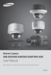
1
Network Camera SNB-5000/SND-5080/SND-5080F/SNV-5080 User Manual Before installing and operating this product, please read this manual thoroughly. English overview IMPORTANT SAFETY INSTRUCTIONS 1. Read these instructions. 2. Keep these instructions. 3. Heed all warnings. 4. Follow all instructions. 5. Do not use this apparatus near water. 6. Clean only with dry cloth. 7. Do not block any ventilation openings, Install in accordance with the manufacturer’s instructions. 8. Do not install near any heat sources such as radiators, heat reaisters, stoves, or other apparatus (including amplifiers) that produce heat. 9. Do not defeat the safety purpose of the polarized or grounding-type plug, A polarized plug has two blades with one wider than the other. A grounding type plug has two blades and a third grounding prong. The wide blade or the third prong are provided for your safety, If the provided plug does not fit into your outlet, consult an electrician for replacement of the obsolete outlet. 10. Protect the power cord from being walked on or pinched particularly at plugs, convenience receptacles, and the point where they exit from the apparatus. 11. Only use attachments/ accessories specified by the manufacturer. 12. Use only with the cart, stand, tripod, bracket, or table specified by the manufacturer, or sold with the apparatus. When a cart is used. Use caution when moving the cart/apparatus combination to avoid injury from tip-over. 13. Unplug this apparatus during lighting storms or when unused for long periods of time. 14. Refer all servicing to qualified service personnel. Servicing is required when the apparatus has been damaged in any way, such as power-supply cord or plug is damaged, liquid has been spilled or objects have fallen into the apparatus, the apparatus has been exposed to rain or moisture, does not operate normally, or has been dropped. 2_ overview WARNING TO REDUCE THE RISK OF FIRE OR ELECTRIC SHOCK, DO NOT EXPOSE THIS PROCUCT TO RAIN OR MOISTURE. DO NOT INSERT ANY METALLIC OBJECT THROUGH THE VENTILATION GRILLS OR OTHER OPENNINGS ON THE EQUIPMENT. Apparatus shall not be exposed to dripping or splashing and that no objects filled with liquids, such as vases, shall be placed on the apparatus M OVERVIEW CAUTION CAUTION RISK OF ELECTRIC SHOCK. DO NOT OPEN CAUTION : TO REDUCE THE RISK OF ELECTRIC SHOCK. DO NOT REMOVE COVER (OR BACK). NO USER SERVICEABLE PARTS INSIDE. REFER SERVICING TO QUALIFIED SERVICE PERSONNEL. EXPLANATION OF GRAPHICAL SYMBOLS The lightning flash with arrowhead symbol, within an equilateral triangle, is intended to alert the user to the presence of “dangerous voltage” within the product’s enclosure that may be of sufficient magnitude to constitute a risk of electric shock to persons. The exclamation point within an equilateral triangle is intended to alert the user to the presence of important operating and maintenance (servicing) instructions in the literature accompanying the product. Class construction An apparatus with CLASS construction shall be connected to a MAINS socket outlet with a protective earthing connection. Battery Batteries(battery pack or batteries installed) shall not be exposed to excessive heat such as sunshine, fire or the like. English _3 overview Disconnection Device Disconnect the main plug from the apparatus, if it’s defected. And please call a repair man in your location. When used outside of the U.S., it may be used HAR code with fittings of an approved agency is employed. CAUTION These servicing instructions are for use by qualified service personnel only. To reduce the risk of electric shock do not perform any servicing other than that contained in the operating instructions unless you are qualified to do so. The BNC output port is used to monitor the installation process of the network camera. If you keep the BNC cable connected, a risk of lightening may cause damage or malfunction to the product. 4_ overview Please read the following recommend safety precautions carefully. Do not install on a surface where it is exposed to direct sunlight, near heating equipment or heavy cold area. Do not place this apparatus near. Do not attempt to service this apparatus yourself. Do not place a glass of water on the product. Do not install near any magnetic sources. Do not block any ventilation openings. Do not place heavy items on the product. User’s Manual is a guidance book how to use the products The meaning of the using sign in the book is following y Reference : In case of providing information for helping of product’s usages y Notice : If there’s any possibility to occur any damages for the goods and human caused by not following the instruction Ú Please read this manual for the safety before using of goods and keep it in the safe place. English _5 M OVERVIEW Do not Place this apparatus on an uneven surface. overview This equipment has been tested and found to comply with the limits for a Class A digital device, pursuant to part 15 of the FCC Rules. These limits are designed to provide reasonable protection against harmful interference when the equipment is operated in a commercial environment. This equipment generates, uses, and can radiate radio frequency energy and, if not installed and used in accordance with the instruction manual, may cause harmful interference to radio communications. Operation of this equipment in a residential area is likely to cause harmful interference in which case the user will be required to correct the interference at his own expense. Samsung Techwin cares for the environment at all product manufacturing stages, and is taking measures to provide customers with more environmentally friendly products. The Eco mark represents Samsung Techwin’s devotion to creating environmentally friendly products, and indicates that the product satisfies the EU RoHS Directive. Correct Disposal of This Product (Waste Electrical & Electronic Equipment) (Applicable in the European Union and other European countries with separate collection systems) This marking on the product, accessories or literature indicates that the product and its electronic accessories (e.g. charger, headset, USB cable) should not be disposed of with other household waste at the end of their working life. To prevent possible harm to the environment or human health from uncontrolled waste disposal, please separate these items from other types of waste and recycle them responsibly to promote the sustainable reuse of material resources. Household users should contact either the retailer where they purchased this product, or their local government office, for details of where and how they can take these items for environmentally safe recycling. Business users should contact their supplier and check the terms and conditions of the purchase contract. This product and its electronic accessories should not be mixed with other commercial wastes for disposal. 6_ overview CONTENTS OVERVIEW INSTALLATION & CONNECTION 24 Important Safety Instructions Product Features Recomended PC Specifications What’s Included At a Glance (SNB-5000) At a Glance (SND-5080) At a Glance (SND-5080F) At a Glance (SNV-5080) 24 26 28 32 33 Installation (SND-5080) Installation (SND-5080F) Installation (SNV-5080) Mounting the Lens Inserting/Removing an SD Memory Card Memory Card Information (Not Included) Connecting with other Device 36 37 NETWORK CONNECTION AND SETUP 42 42 43 44 45 46 47 50 51 52 52 Connecting the Camera Directly to Local Area Networking Connecting the Camera Directly to a DHCP Based DSL/Cable Modem Connecting the Camera Directly to a PPPoE Modem Connecting the Camera to an IP Router with the PPPoE/Cable Modem IP Address Setup Static IP Setup Dynamic IP Setup Port Range Forward (Port Mapping) Setup Connecting to the Camera from a Shared Local PC Connecting to the Camera from a Remote PC via the Internet English _7 M OVERVIEW 2 2 9 9 10 12 15 18 21 overview CAMERA SETUP 53 WEB VIEWER 62 SETUP SCREEN 70 APPENDIX 87 8_ overview 53 53 How to use the Menu Key Camera Menu Setup 62 63 64 66 67 68 Connecting to the Camera Login Installing Silverlight Runtime Using the Live Screen Using OSD Screen Menu Playback 70 70 73 77 83 Setup Audio & Video Setup Network Setup Event Setup System Setup 87 89 91 93 Camera Specification Network Specification Troubleshooting GPL/LGPL Software License PRODUCT FEATURES RECOMENDED PC SPECIFICATIONS y CPU : Pentium4 / 2.4GHz or higher y Operating System : Windows XP, VISTA, 7 Mac OS y Resolution : 1280X1024 pixels or higher y RAM : 1GB or higher y Web Browser : Internet Explorer 7.0 or higher Firefox, Google Chrome, Safari y Video Memory : 128MB or higher English _9 M OVERVIEW y HD Video Quality Supports up to 1.3 mega pixels of HD video quality. y H.264/MPEG-4/MJPEG Multi-Streaming This network camera supports the H.264/MPEG-4/MJPEG codec and can display videos in different resolutions and qualities simultaneously with different Codecs. y Support various communication protocols Supports TCP/IP, UDP, RTP/RTSP, email, and FTP protocols as well as various internet protocols such as ARP, HTTP, HTTPS and DHCP. y Web Browser-based Monitoring Using the Internet web browser to display the image in a local network environment. y Alarm If an event occurs, the event-related video will be transferred to the FTP/email specified by the user or saved to the SD memory, or the event signal will be sent to the ALARM OUT port. y Intelligent Video Analysis Analyzes the event video according to the user-specified rules to recognize the event. y ONVIF (Spec 1.01) Compliance This product supports ONVIF Core Spec. 1. 01. For more information, refer to www.onvif.org. overview WHAT’S INCLUDED Please check if your camera and accessories are all included in the product package. Appearance 10_ overview Item Name Quantity Description Model Name User Manual/ IP Installer DVD 1 User Manual 1 Power Adapter 1 Used for connecting to the power source Jack Modular 1 LAN cable gender Cable for the testing monitor 1 Used to test the camera connection to a portable display device Alarm Cable 1 Used to connect to Alarm I/O Template 1 Product installation guide SND-5080F SNV-5080 Iron Screw 3 Used for fixing to an iron plate SND-5080/5080F Dustproof Plate 1 Preventing dust inflow SND-5080 SNB-5000 SND-5080/5080F SNV-5080 SND-5080/5080F SNV-5080 Appearance Quantity Description C Mount Adapter Auto Iris Lens Connector 1 Used to install the camera lens Camera Holder (Mount) 1 Used to install the camera holder Camera Holder (Mount) Screws 2 Used to install the mount ASSY-Screw Tapping 4 Used for installation on the wall or ceiling L Wrench 1 Used to remove/fix the dome cover Plastic Anchor 4 For fixing a screw, Inserted in a hole (reinforced anchoring force) Model Name SNB-5000 M OVERVIEW Item Name SNV-5080 Tapping Screw SND-5080F Bracket Safety Lens Options (not included) CS Lens Optional lens to be inserted in a camera SNB-5000 C Lens M The Test Monitor Cable is connected to a portable displayer and used for testing the camera. If you intend to use it for an actual monitoring camera, use the BNC cable instead. English _11 overview AT A GLANCE (SNB-5000) Front Side SNB-50 www.sam 00 sungcc tv.c om Item M Description Camera Holder (Mount) Holes Used when you mount the camera onto the bracket by fixing the camera holder (mount) adaptor with the bracket. Auto Iris Lens (Optional) Installed on the lens adaptor. Auto Iris Lens Connector Used to supply power and output signal to control the iris of the lens. Wipe out a dirty surface of the lens softly with a lens tissue or cloth to which you have applied ethanol. 12_ overview Rear Side AUDIO OUT AUDIO IN SD CARD SD SYSTEM POWER 1 2 3 4 5 1 : ALARM IN 4 : 2 : ALARM OUT 5 : GND 3 : ALARM COM Item SD Memory Card Compartment M OVERVIEW VIDEO RESET NETWORK ACT LINK GND AC 24V DC 12V Description Compartment for the SD memory card. AUDIO OUT Terminal for audio output. AUDIO IN Terminal for audio input. Audio terminal ON : A memory card is inserted and operates normally. SD Flashing : Failed to record, insufficient space, or inserted abnormally. OFF : Camera is off, camera is restarting, or memory card is not in place. System, Power, SD Indicators ON : The camera is turned on and connected to the network properly. SYSTEM Blinking : During DDNS setup, or in case of setup failure, or in a state of unstable network connection OFF : When the system is rebooting, or turned off POWER ON : While the power is on OFF : If the power is off English _13 overview Resets the camera settings to the default. Press and hold it for about 5 seconds to turn off the system indicator and restart the system. Reset Button J Resetting the camera requires reconfiguration of network settings (IP address, subnet mask, gateway address etc.) using the IP Installer software application. Power Port Used to plug the power cable. GND Used for earth-grounding. Network Port Used to connect a PoE or LAN cable. ALARM IN Used to connect the alarm input signal. ALARM OUT Used to connect the alarm output signal. I/O Port ALARM COM Common port where the alarm output signal is connected. GND Video Out Port 14_ overview Used for earth-grounding. Video signal output port connected to the monitor. AT A GLANCE (SND-5080) Appearance M OVERVIEW Item Description Dome Cover Dome cover for the lens and unit protection. Main unit Main unit includes the lens, switch board, PCB boards and screws. Power Port Used to plug the power cable. Video Out Port Video signal output port connected to the monitor. Network Port Used to connect a PoE or LAN cable. Audio In Jack Used to connect to a microphone. Audio Out Jack Used to connect to speakers. English _15 overview Inside 3 Item Alarm In / Out terminals SD Memory Card Compartment Description ALARM IN Used to connect the alarm input signal. ALARM OUT Used to connect the alarm output signal. ALARM COM Common port where the alarm output signal is connected. GND Used for earth-grounding. Compartment for the SD memory card. Resets the camera settings to the default. Press and hold it for about 5 seconds to turn off the system indicator and restart the system. Reset Button 16_ overview J Resetting the camera requires reconfiguration of network settings (IP address, subnet mask, gateway address etc.) using the IP Installer software application. Components 1 2 7 8 Item Description Inner Cover Cover for the main unit’s protection. Side wing hooks By lifting it while gently pressing the both ends, you can separate the inner cover. ZOOM lever Turn the barrel left or right to adjust the zoom, and turn the knob clockwise to lock the zoom. Focus lever Turn the barrel left or right to adjust the focus, and turn the knob clockwise to lock the focus. SD Memory Card Compartment Compartment for the SD memory card. Monitor Out Using the test monitor cable, you can connect to a mobile display for camera test. 7 Wiring Cover If you drill a hole in the wiring cover for wiring, remove the cover and attach the provided dustproof plate to it, and arrange the cables through the plate. The dust-proof plate is to prevent outside dust from inflow to the wiring compartment. 8 Lock Release To separate the bracket from the main unit for the installation or to separate the camera from an installed camera, push this release and turn the main unit in the marked direction of <UNLOCK>. 6 English _17 M OVERVIEW 3 4 5 6 overview AT A GLANCE (SND-5080F) Appearance Item 7 Description Dome Cover Dome cover for the lens and unit protection. Main unit Main unit includes the lens, switch board, PCB boards and screws. Power Port Used to plug the power cable. Video Out Port Video signal output port connected to the monitor. Network Port Used to connect a PoE or LAN cable. Audio In Jack Used to connect to a microphone. Audio Out Jack Used to connect to speakers. 18_ overview Inside M OVERVIEW 3 Item Description ALARM IN Alarm In / Out terminals ALARM OUT Used to connect the alarm output signal. ALARM COM Common port where the alarm output signal is connected. GND SD Memory Card Compartment Used to connect the alarm input signal. Used for earth-grounding. Compartment for the SD memory card. Resets the camera settings to the default. Press and hold it for about 5 seconds to turn off the system indicator and restart the system. Reset Button J Resetting the camera requires reconfiguration of network settings (IP address, subnet mask, gateway address etc.) using the IP Installer software application. English _19 overview Components 3 4 5 Item Description Inner Cover Cover for the main unit’s protection. Side wing hooks By lifting it while gently pressing the both ends, you can separate the inner cover. ZOOM lever Turn the barrel left or right to adjust the zoom, and turn the knob clockwise to lock the zoom. Focus lever Turn the barrel left or right to adjust the focus, and turn the knob clockwise to lock the focus. Monitor Out Using the test monitor cable, you can connect to a mobile display for camera test. 20_ overview AT A GLANCE (SNV-5080) Appearance M OVERVIEW Item Description Dome Cover Dome cover for the lens and unit protection. Main unit Main unit includes the lens, switch board, PCB boards and screws. Power Port Used to plug the power cable. Video Out Port Video signal output port connected to the monitor. Network Port Used to connect a PoE or LAN cable. Audio In Jack Used to connect to a microphone. Audio Out Jack Used to connect to speakers. English _21 overview Inside 3 Item Description ALARM IN Alarm In / Out terminals ALARM OUT Used to connect the alarm output signal. ALARM COM Common port where the alarm output signal is connected. GND SD Memory Card Compartment Used to connect the alarm input signal. Used for earth-grounding. Compartment for the SD memory card. Resets the camera settings to the default. Press and hold it for about 5 seconds to turn off the system indicator and restart the system. Reset Button 22_ overview J Resetting the camera requires reconfiguration of network settings (IP address, subnet mask, gateway address etc.) using the IP Installer software application. Components 3 4 Item Description Inner Cover Cover for the main unit’s protection. Side wing hooks By lifting it while gently pressing the both ends, you can separate the inner cover. ZOOM lever Turn the barrel left or right to adjust the zoom, and turn the knob clockwise to lock the zoom. Focus lever Turn the barrel left or right to adjust the focus, and turn the knob clockwise to lock the focus. Monitor Out Using the test monitor cable, you can connect to a mobile display for camera test. English _23 M OVERVIEW 5 installation & connection INSTALLATION (SND-5080) Precautions before installation Ensure you read out the following instructions before installing the camera: y Select an installation site (ceiling or wall) that can endure at least 5 times of the camera weight. y Stuck-in or peeled-off cables can cause damage to the product or a fire. y For safety purposes, keep anyone else away from the installation site. And put aside personal belongings from the site, just in case. Installing the camera 1. Hold down the bottom lock lever while removing the cover with the other hand. Removing the cover reveals the main unit and inner cover. 24_ installation & connection 2. To fix the camera position, hold down either hook of the inner cover and lift it up. M INSTALLATION & CONNECTION 3. Push the release lock out while turning the main unit in the <UNLOCK> direction to remove the bracket. If this doesn't work, use the hole on the bottom of the bracket to turn the bracket in the <LOCK>direction. 4. Use the provided screws (x3) to fix the bracket to a desired position (ceiling or wall). Ensure that the <CAMERA FRONT> label on the bracket faces the direction for camera monitoring. 5. Arrange the cables through the bracket to the ceiling or wall. If you drill a hole in the ceiling cover for wiring, press hard to remove the cover and attach the dust-proof plate to it, and arrange the cables through the plate. If you intend to arrange the cables without drilling a hole, use the empty area opposite to the <CAMERA FRONT> label side for the wiring purpose. 6. Mount the main unit onto the bracket. Align the marking hole of the main unit with the <CAMERA FRONT> label of the bracket, and turn the unit in the <LOCK> direction. Wiring Cover 7. Adjust the lens in a desired direction. For adjusting the lens direction, refer to "Adjusting the monitoring direction for the camera". (page 31) 8. Secure the inner cover to the main unit. Fit the two holes of the wing-side locks on the inner cover into the corresponding hole of the main unit, and press it down until you hear a click. 9. Fix the cover to the main unit. Fit the protruding part inside the cover into the corresponding hole of the main unit, and turn the cover to fix it. English _25 installation & connection INSTALLATION (SND-5080F) Removing the dome cover 1. Hold down the bottom lock lever while removing the cover with the other hand. Removing the cover reveals the main unit and inner cover. 2. To fix the camera position, hold down both hooks of the inner cover while lifting it up. Ceiling Mount 1. Use the provided template to drill one hole for the camera, and one for the screw (5 mm in diameter, at least 35 mm in depth), and insert the plastic anchor (HUR 5) to the end of the screw hole. 2. Connect and arrange the necessary cables (power, video, etc) lest that they should be damaged or caught while installing the camera. 26_ installation & connection 3. Insert the camera assembly into the hole so that it fits to the camera hole, and fix the assembly using the assembly screw tappings (TH, M4xL30). (x3) 4. Close the dome cover. M INSTALLATION & CONNECTION 5. Fix the cover to the main unit. Fit the protruding part inside the cover into the corresponding hole of the main unit, and turn the cover to fix it. To add an alarm cable 1. For this, first you should remove the dome cover from the housing. 2. Pull out the protruding rubber bar as shown. 3. This will reveal a hole in the place of the rubber bar, through which you insert the cable, and connect it to the alarm terminal on the PCB. 4. Connect and arrange the necessary cables (power, video, etc) lest that they should be damaged or caught while installing the camera. Then, install the camera assembly in the reverse order of the disassembly. 5. Adjust the lens in a desired direction and close the dome cover. English _27 installation & connection INSTALLATION (SNV-5080) Disassembling To connect the alarm in/out, the dome cover and lens cover are to be separated. 1. Using the L-wrench provided, loosen 3 screws by turning them counterclockwise and separate the dome cover. 2. Lift up the inner cover while gently pressing its both ends to separate it from the unit. 28_ installation & connection Optional Accessories for Installation For your easier installation, you can purchase appropriate optional accessories available. 1. WALL MOUNT ADAPTOR(SCX-300WM)/ HANGING MOUNT(SCX-300HM) This adaptor is used when installing the dome camera onto a wall. M INSTALLATION & CONNECTION 2. CEILING MOUNT ADAPTOR(SCX-300CM)/ HANGING MOUNT(SCX-300HM) This adaptor is used when installing the dome camera on a concrete ceiling. 3. POLE MOUNT ADAPTOR(SCX-300PM) This is an adaptor for WALL MOUNT ADAPTOR (SCX-300WM) installation on a pole whose diameter is bigger than 80mm. English _29 installation & connection 4. CORNER MOUNT ADAPTOR (SCX-300KM) This is an adaptor for WALL MOUNT ADAPTOR (SCX-300WM) installation on the corner of wall joint. Installing on the ceiling directly 1. Using the L-wrench provided, loosen 3 screws by turning them counterclockwise and separate the dome cover. 2. Loosen 3 screws by turning them counterclockwise, press both left and right lock releases inwards (in arrow direction) to unlock the stopper, and then separate the camera from the case. 30_ installation & connection 3. Drill holes (diameter 5mm, more than 35mm deep) on the ceiling by matching to the holes on the case bed, and insert plastic anchors (HUD 5) fully into the holes. Fix the case bed on the ceiling by using Tapping Screws (TH M4xL30). (4 places) 5. Adjust the lens aiming to your desired direction. 6. Assemble the Dome Cover. For waterproof purpose, fix and secure the bolt using L-wrench provided. M For the wall mounting installation and how to connect the alarm cables, refer to the installation instructions of SND-5080F. (pages 26~27) Adjusting the monitoring direction for the camera (SND-5080/SND5080F/SNV-5080) Panning Tilting Lens rotation You can adjust the camera direction only when the camera is fixed on the ceiling. Then, turning the camera to the left or right is referred to as "Panning", while tilting the angle is "Tilting". For panning, the panning limit is 220° for the clockwise, and 120° for the counterclockwise, a total of 340° enabled; further rotation is stopped by the stopper. English _31 M INSTALLATION & CONNECTION 4. Connect power and video cables and arrange cable running not to damage or squeeze them, and assemble the camera unit in the reverse way. installation & connection MOUNTING THE LENS Disconnect the power before proceeding. M The C lens and CS lens are not included in the product package. You must use the mega lens only for this purpose. Mounting the CS lens Turn the optional CS lens clockwise to insert it. SNB-50 www.sam 00 sungcc tv.c om CS Lens Mounting the C lens Turn the C mount adaptor clockwise to insert it and do the same with the C lens. SNB-50 www.sam 00 sungcc tv.c om 32_ installation & connection C Lens Connecting the Auto Iris Lens connector Insert the lens connector into the corresponding hole of the camera. www.sam 00 sungcc tv.c om Focusing Turn the lens left or right to control the zoom and focus the lens so that you can view a clear, sharp object. INSERTING/REMOVING AN SD MEMORY CARD Inserting an SD Memory Card Push the SD memory card in the direction of the arrow shown in the diagram. 000 .com SNB-5msungcctv www.sa English _33 M INSTALLATION & CONNECTION SNB-50 installation & connection J Do not insert the SD memory card while it’s upside down by force. Otherwise, it may damage the SD memory card. Removing an SD Memory Card Gently press down on the exposed end of the memory card as shown in the diagram to eject the memory card from the slot. 000 .com SNB-5msungcctv www.sa 34_ installation & connection M INSTALLATION & CONNECTION J Pressing too hard on the SD memory card can cause the card to shoot out uncontrollably from the slot when released. To remove the SD memory card, set <Record> to OFF from <SD Record> and press [Apply]. (page 78) If you saved data in the SD memory card, removing the SD memory card will cause damage to the data stored in the card. If the SD memory is inserted, the SD LED indicator on the rear of the camera will turn on. If there occurs a problem in the SD memory, the SD LED indicator will blink. English _35 installation & connection MEMORY CARD INFORMATION (NOT INCLUDED) What is a memory card? The memory card is an external data storage device that has been developed to offer an entirely new way to record and share video, audio, and text data using digital devices. Selecting a memory card that’s suitable for you Your camera supports SDHC memory cards. You may, however, experience compatibility issues depending on the model and make of the memory card. For your camera, we recommend you use a memory card from the following manufacturers: SDHC/SD Memory Card : Sandisk, Transcend, Kingston Your camera supports 2GMB to 32GB of memory card capacity. Playback performance can be affected depending on the speed of memory card, so use the high-speed memory card. To ensure proper recording of video data, we recommend you use a memory card that supports at least read/write speed 10Mbps and Class 6. Memory Card Use SD and SDHC memory cards feature a switch that disables writing data on to the media. Having this switch to the Lock position will prevent accidental deletion of data stored in the memory card but at the same time will also prevent you from writing data on to the media. W Memory Card Components Contacts Lock Switch SD/SDHC 36_ installation & connection CONNECTING WITH OTHER DEVICE SD M INSTALLATION & CONNECTION AUDIO OUT AUDIO IN Monitor SD CARD SYSTEM POWER VIDEO RESET 1 2 3 4 5 1 : ALARM IN 4 : 2 : ALARM OUT 5 : GND 3 : ALARM COM NETWORK ACT LINK GND AC 24V DC 12V Power Network Monitor Out Power Monitor Network English _37 installation & connection Connecting to the monitor Connect the [VIDEO] port of the camera to the video input port of the monitor. M In the initial installation of the camera, you can connect the camera to the monitor for checking the connection status. You must set <Video Output> to <ON> before the display screen can be activated. (page 72) Connect the monitor test cable to the output port of the monitor. Ethernet Connection Connect the Ethernet cable to the local network or to the Internet. Power Supply Use the screwdriver to connect each line (+, –) of the power cable to the corresponding power port of the camera. J Be careful not to reverse the polarity when you connect the power cable. M The instructions above are also applied to SND-5080/SND-5080F/SNV-5080. You can also use a router featuring PoE (Power over Ethernet) to supply power to the camera. 38_ installation & connection Connecting to Audio Input/Output Microphone Network 00 tv.com SNB-am50sungcc www.s Speaker Amp Amp Microphone Amp Microphone Microphone Speaker Amp English _39 M INSTALLATION & CONNECTION PC installation & connection 1. Connect the AUDIO IN port of the camera with the microphone directly or LINE OUT port of the amplifier that the microphone is connected to. 2. Connect the AUDIO OUT port of the camera with the LINE IN port of the speaker. 3. Check the specifications for audio input. y Audio Codec G.711 PCM. μ-law 64kbps 8kHz sampling y Full duplex Audio y Audio in Used for mono signal line input (Max.2.4 Vpp) y Audio out Used for mono signal line output (Max.2.4 Vpp) y Line out impedance 600 Alarm I/O Wiring Diagram ALARM IN 1 ALARM OUT 2 ALARM COM 3 4 GND 5 40_ installation & connection (5mA sink) (30VDC 2A, 125VAC 0.5A MAX) Connecting to the I/O port box Connect the Alarm I/O signal to the corresponding port of the rear port box. AUDIO OUT AUDIO IN 1 2 3 4 5 SD CARD SD SYSTEM POWER RESET 1 2 3 4 5 1 : ALARM IN 4 : 2 : ALARM OUT 5 : GND 3 : ALARM COM 1 : ALARM IN 4 : 2 : ALARM OUT 5 : GND 3 : ALARM COM NETWORK ACT LINK GND AC 24V DC 12V <SNB-5000> 5 4 3 2 1 1 : ALARM IN 4 : 2 : ALARM OUT 5 : GND 3 : ALARM COM <SND-5080/SND-5080F/SNV-5080> y y y y ALARM IN : Used to connect the alarm input signal. ALARM OUT : Used to connect the alarm output signal. ALARM COM : Common port where the alarm output signal is connected. GND : Used for earth-grounding. English _41 M INSTALLATION & CONNECTION VIDEO network connection and setup You can set up the network settings according to your network configurations. CONNECTING THE CAMERA DIRECTLY TO LOCAL AREA NETWORKING Connecting to the camera from a local PC in the LAN 1. Launch an Internet browser on the local PC. 2. Enter the IP address of the camera in the address bar of the browser. SNB-50 www.samsu00 ngcctv.com Camera INTERNET SNB-50 www.samsu00 ngcctv.com Camera Local PC External Remote PC Firewall DDNS Server (Data Center, KOREA) <Local Network> M A remote PC in an external Internet out of the LAN network may not be able to connect to the camera installed in the intranet if the port-forwarding is not properly set or a firewall is set. In this case, to resolve the problem, contact your network administrator. 42_ network connection and setup CONNECTING THE CAMERA DIRECTLY TO A DHCP BASED DSL/CABLE MODEM INTERNET SNB-50 www.samsu00 ngcctv.com DSL/Cable Modem External Remote PC Camera 1. Use the cross LAN cable to connect the network cable directly to your PC. 2. Run the IP Installer and change the IP address of the camera so that you can use the web browser on your desktop to connect to the Internet. 3. Use the Internet browser to connect to the camera. 4. Move to [Setup] page. 5. Move to [Network] – [DDNS] and configure the DDNS settings. 6. Move to [Network] – [Interface], and set the network type to [DHCP]. 7. Connect the camera, which was removed from your PC, directly to the modem. 8. Restart the camera. M For registering the DDNS settings, refer to "DDNS". (page 74) For configuring the DDNS settings, refer to "Registering with DDNS". (page 76) For setting the network type, refer to "Interface". (page 73) English _43 M NETWORK CONNECTION AND SETUP DDNS Server (Data Center, KOREA) network connection and setup CONNECTING THE CAMERA DIRECTLY TO A PPPOE MODEM INTERNET SNB-50 www.samsu00 ngcctv.com PPPoE Modem External Remote PC Camera DDNS Server (Data Center, KOREA) 1. Use the cross LAN cable to connect the network cable directly to your PC. 2. Run the IP Installer and change the IP address of the camera so that you can use the web browser on your desktop to connect to the Internet. 3. Use the Internet browser to connect to the camera. 4. Move to [Setup] page. 5. Move to [Network] – [DDNS] and configure the DDNS settings. 6. Move to [Network] – [Interface], and set the network type to [PPPoE]. 7. Connect the camera, which was removed from your PC, directly to the modem. 8. Restart the camera. M For registering the DDNS settings, refer to "DDNS". (page 74) For configuring the DDNS settings, refer to "Registering with DDNS". (page 76) For setting the network type, refer to "Interface". (page 73) 44_ network connection and setup CONNECTING THE CAMERA TO AN IP ROUTER WITH THE PPPOE/CABLE MODEM This is for a small network environment such as homes, SOHO and ordinary shops. SNB-50 www.samsu00 ngcctv.com INTERNET www.samsu00 ngcctv.com Camera IP Router PPPoE or Cable Modem PPPoE or Cable Modem External Remote PC Local PC DDNS Server (Data Center, KOREA) Configuring the network settings of the local PC connected to an IP router Configuring the network settings of the local PC connected to an IP router, follow the instructions below. y Select : <Network Neighborhood> <Properties> <Local Area Connection> <Properties> <General> <Internet Protocol (TCP/IP)> <Properties> <Obtain an IP address automatically> or <Use the following IP address>. y Follow the instructions below if you select <Use the following IP address>: ex1) If the address (LAN IP) of the IP router is 192.168.1.1 IP address : 192.168.1.100 Subnet Mask : 255.255.255.0 Default Gateway : 192.168.1.1 ex2) If the address (LAN IP) of the IP router is 192.168.0.1 IP address : 192.168.0.100 Subnet Mask : 255.255.255.0 Default Gateway : 192.168.0.1 ex3) If the address (LAN IP) of the IP router is 192.168.xxx.1 IP address : 192.168.xxx.100 Subnet Mask : 255.255.255.0 Default Gateway : 192.168.xxx.1 M For the address of the IP router, refer to the product’s documentation. English _45 M NETWORK CONNECTION AND SETUP Camera SNB-50 network connection and setup IP ADDRESS SETUP Buttons used in IP Installer Item Description Device Name Model name of the connected camera. Click the column to sort the list by model name. However, search will be stopped if clicked during the search. Mode Displays either <Static> or <Dynamic> for the current network connection status. MAC(Ethernet) Address Ethernet address for the connected camera. Click the column to sort the list by Ethernet address. However, search will be stopped if clicked during the search. IP Address IP address. Click the column to sort the list by IP address. However, search will be stopped if clicked during the search. The factory default is "192.168.1.100" Protocol Network setting for the camera. The factory default is "IPv4". Cameras with the IPv6 setting will be displayed "IPv6". 46_ network connection and setup This function is not currently implemented. URL DDNS URL address enabling access from the external Internet. However, this will be replaced with the <IP Address> of the camera if DDNS registration has failed. IPv4 Scans for cameras with the IPv4 setting. IPv6 Scans for cameras with the IPv6 setting. Search Scans for cameras that are currently connected to the network. However, this button will be grayed out if neither IPv4 nor IPv6 is checked. Auto Set <IP Installer> will automatically configure the network settings for you. Manual Set You should configure the network settings manually. Exit Exits the IP Installer program. STATIC IP SETUP Manual Network Setup Run <IP Installer.exe> to display the camera search list. At the initial startup, both [Auto Set] and [Manual Set] will be grayed out. M For cameras found with the IPv6 setting, these buttons will be grayed out as the cameras do not support this function. 1. Select a camera in the search list. Find the MAC (Ethernet) address labeled on the rear of the camera. Both the [Auto Set] and [Manual Set] buttons will be activated. 2. Click [Manual Set]. The Manual Setting dialog appears. The default values of <IP Address>, <Subnet Mask>, <Gateway>, <HTTP Port> and <VNP Port> of the camera will be displayed. The default <Password> is 4321. English _47 M NETWORK CONNECTION AND SETUP UPnP Status network connection and setup 3. In the <Address> pane, provide the necessary information. MAC (Ethernet) Address : The MAC (Ethernet) address of the applicable camera will be set automatically so you don't need to input it manually. If using an IP router y IP Address : Enter an address falling in the IP range provided by the IP router. ex) 192.168.1.2~254, 192.168.0.2~254, 192.168.XXX.2~254 y Subnet Mask : The <Subnet Mask> of the IP router will be the <Subnet Mask> of the camera. y Gateway : The <Local IP Address> of the IP router will be the <Gateway> of the camera. M The settings may differ depending on the connected IP router model. For more information, refer to the user manual of the applicable router. If not using an IP router : For setting <IP Address>, <Subnet Mask>, and <Gateway>, contact your network administrator. 4. In the <Port> pane, provide necessary information. y HTTP Port : Used to access the camera using the Internet browser, defaulted to 80. Use the spin button to change the HTTP Port value. y VNP Port : Used to control the video signal transfer, defaulted to 4520. 5. Enter the password. This is the login password for the "admin" user who accesses the camera. The default password is "4321". 6. Click [OK]. Manual network setup will be completed. 7. When the manual setup including <IP> is completed, the camera will restart. 48_ network connection and setup If the IP router has more than one camera connected Configure the IP related settings and the Port related settings distinctly with each other. Category Camera #1 Camera #2 IP Address Subnet Mask Gateway 192.168.1.200 255.255.255.0 192.168.1.1 192.168.1.201 255.255.255.0 192.168.1.1 Port related settings HTTP Port VNP Port 80 4520 10000 4530 M If the <HTTP Port> is set other than 80, you must provide the <Port> number in the address bar of the Internet browser before you can access the camera. ex) http://IP address : HTTP Port http://192.168.1.201:10000 Auto Network Setup Run <IP Installer.exe> to display the camera search list. At the initial startup, both [Auto Set] and [Manual Set] will be grayed out. M For cameras found with the IPv6 setting, these buttons will be grayed out as the cameras do not support this function. 1. Select a camera in the search list. Find the MAC (Ethernet) address labeled on the rear of the camera. Both the [Auto Set] and [Manual Set] buttons will be activated. 2. Click [Auto Set]. The Auto Setting dialog appears. The <IP Address>, <Subnet Mask>, and <Gateway> will be set automatically. 3. Enter the password. This is the login password for the "admin" user who accesses the camera. The default password is "4321". 4. Click [OK]. Auto network setup will be completed. 5. The camera will automatically complete the network setting and restart. English _49 M NETWORK CONNECTION AND SETUP IP related settings network connection and setup DYNAMIC IP SETUP Dynamic IP Environment Setup y Example of the dynamic IP environment - If an IP router, with cameras connected, is assigned an IP address by the DHCP server - If connecting the camera directly to modem using the DHCP protocols - If IPs are assigned by the internal DHCP server via the LAN Checking the dynamic IP 1. From a local PC, run <IP Installer> to display a list of cameras that are assigned <Dynamic IP>. 2. Select a camera in the list, and click [Manual Set] to check the <Dynamic IP> of the camera. If you uncheck <DHCP>, you can change <IP> or <Port> to <Static>. 50_ network connection and setup PORT RANGE FORWARD (PORT MAPPING) SETUP If you have installed an IP router with a camera connected, you must set the port range forwarding on the IP router so that a remote PC can access the camera in it. Manual Port Range Forwarding M NETWORK CONNECTION AND SETUP 1. From the Setup menu of the IP router, select <Applications & Gaming> <Port Range Forward>. For setting the port range forward for a third-party IP router, refer to the user guide of that IP router. 2. Select <TCP> and <UDP Port> for each connected camera to the IP router. Each port number for the IP router should match that specified in <Netwok> - <IP> from the camera's Setup menu. 3. When done, click [Save Settings]. Your settings will be saved. M The settings may differ depending on the connected IP router model. For more information, refer to the user manual of the applicable router. English _51 network connection and setup CONNECTING TO THE CAMERA FROM A SHARED LOCAL PC 1. Launch <IP Installer>. It will scan for connected cameras and display a list of them. 2. Double-click a camera to access. The Internet browser starts and connects to the camera. M You can also access the camera in such way you type the IP address of the found camera in the address bar of the Internet browser. CONNECTING TO THE CAMERA FROM A REMOTE PC VIA THE INTERNET As a remote PC can not directly access <IP Installer>, you should access the camera in the IP router network using DDNS URL of the camera. 1. Before you can access a camera in the IP router network, you should have set the port range forward for the IP router. 2. From the remote PC, launch the Internet browser and type the DDNS URL address of the camera, or the IP address of the IP router in the address bar. ex) http://www.samsungipolis.com/[Product ID] 52_ network connection and setup camera setup HOW TO USE THE MENU KEY Follow the steps below if you run the Web Viewer for setting the menus. 1. Launch the Web Viewer. M CAMERA SETUP 2. Click [Camera Menu ( )] in the left corner of the Live screen. The camera setup menu appears. 3. Use the Up/Down (▲/▼) buttons to move to a desired item. 4. To change the value of a selected item, use the Left/Right (◄/►) buttons. To break down to a sub-menu structure, )] on the selected item. click [Enter ( : This arrow appears next to a menu that contains sub items. J If <IV analysis function> is enabled, camera’s OSD menu operation can be set as an event. CAMERA MENU SETUP You can change the camera settings according to the environment where the camera is located. SSDR (Samsung Super Dynamic Range) Setup In a scene where the difference between bright and dark is severe, you can increase the brightness of the dark area alone to regulate the overall brightness. ▲/▼ Ö ◄/► Ö ENTER Ö ▲/▼ Ö ◄/► Ö ENTER 1. Move to <SSDR> and select <ON>. MAIN SETUP SSDR WHITE BAL BACKLIGHT EXPOSURE SPECIAL EXIT ON ATW OFF English _53 camera setup 2. Configure the <SSDR> and <D-RANGE> settings as necessary. y SSDR : Adjust the level of the dynamic range. y D-RANGE : Select the amplitude area of the dynamic range. SSDR SETUP SSDR D-RANGE RETURN 8 NARROW 3. When completed, select <RETURN> to return to the previous screen. White Balance Setup You can correct the image colors based on white under any lighting conditions. ▲/▼ Ö ◄/► Ö ENTER Ö ▲/▼ Ö ◄/► Ö ENTER 1. Move to <WHITE BAL> and select a setting value. MAIN SETUP y ATW : Corrects the colors of the camera SSDR ON video automatically. WHITE BAL ATW BACKLIGHT OFF y MANUAL : You can adjust the red and EXPOSURE SPECIAL blue gains of the camera video manually. EXIT y AWC l SET : Corrects the colors of the camera video to be optimized to the current lighting condition and screen mode. You may need readjustment if the lighting condition is changed. Put the focus of the camera to a white paper and press the [Enter ( )] button. y OUTDOOR : Automatically corrects the video colors of the camera to be optimized to the outdoor environment. y INDOOR : Automatically corrects the video colors of the camera to be optimized to the indoor environment. 2. To adjust it manually, select <MANUAL>. 3. Specify the <RED> and <BLUE> values as necessary. 4. When completed, select <RETURN> to return to the previous screen. 54_ camera setup WHITE BAL MANUAL SETUP RED BLUE RETURN 529 532 Custom Backlight Setup You can specify a desired area on the video manually and set the area to be displayed more clearly. ▲/▼ Ö ◄/► Ö ENTER Ö ▲/▼/◄/► Ö ENTER 1. Move to <BACKLIGHT>. MAIN SETUP SSDR WHITE BAL BACKLIGHT EXPOSURE SPECIAL EXIT 3. Set the BLC <LEVEL>. You can change the level to adjust the brightness of the monitoring area. 4. Set the <TOP, BOTTOM, LEFT, RIGHT> levels to specify the target area. 5. When completed, select <RETURN> to return to the previous screen. ON ATW BLC BLC SETUP LEVEL TOP BOTTOM LEFT RIGHT RETURN LOW 30 75 30 70 English _55 M CAMERA SETUP 2. Select <BLC>. camera setup HLC (Highlight Compensation) Setup When a strong light such as streetlamp or headlight faces forward to the camera, you can mask that exposed area in order to protect it from being saturated. ▲/▼ Ö ◄/► Ö ENTER Ö ▲/▼ Ö ◄/► Ö ENTER 1. Select <BACKLIGHT>. 2. Select <HLC>. MAIN SETUP SSDR WHITE BAL BACKLIGHT EXPOSURE SPECIAL EXIT 3. Set the <LEVEL> and the <MASK TONE>. y LEVEL : Adjust the brightness level so as to remove the incoming highlight from a specific condition. y MASK TONE : Adjust the mask tone of the highlighted area. ON ATW HLC HLC SETUP LEVEL MASK TONE RETURN MIDDLE 7 4. When completed, select <RETURN> to return to the previous screen. M At night operation, this function will be activated only if the highlight comes from more than a certain area in a dark environment. At night operation, HLC will not function in too a bright or too a dark scene. 56_ camera setup Exposure Setup You can adjust the exposure level of the camera. ▲/▼ Ö ENTER Ö ▲/▼/◄/► Ö ENTER Ö ▲/▼/◄/► Ö ENTER 1. Move to <EXPOSURE> and select a setting value. MAIN SETUP ON ATW OFF 2. Select each item and set it appropriately. y BRIGHTNESS : Adjust the screen EXPOSURE SETUP brightness. BRIGHTNESS 50 y IRIS : If set to <MANUAL>, you can IRIS AUTO SHUTTER --adjust the iris of the camera manually. AGC HIGH SSNR3 ON y SHUTTER : Adjust the electronic shutter SENS-UP AUTO of the camera. RETURN - MANUAL : Adjust the shutter speed of the camera manually. - A.FLK : This will prevent the screen from flickering. y AGC : Specify how to adjust the level according to the luminance. - MANUAL : Adjust the screen brightness manually. y SSNR3 : Adjust the noise reduction level. SSNR3 LEVEL SETUP LEVEL RETURN 12 English _57 M CAMERA SETUP SSDR WHITE BAL BACKLIGHT EXPOSURE SPECIAL EXIT camera setup y SENS-UP : Automatically senses the darkness level at night or in a low contrast scene and extends the accumulation time accordingly for a bright and sharp image. SENS-UP LIMIT SETUP LIMIT RETURN 2X If you set the shutter mode to MANUAL/ FLICKERLESS, SENS-UP mode will be deactivated. The greater the video accumulation factor is, the brighter the screen is but the afterimage of a moving object grows accordingly. - AUTO : Set the work condition to Auto mode in a low contrast scene. 3. When completed, select <RETURN> to return to the previous screen. Screen Display Setup You can specify the camera title and the OSD color that will be displayed on the screen. ▲/▼ Ö ◄/► Ö ENTER Ö ▲/▼ Ö ◄/► Ö ENTER 1. Select <SPECIAL>. MAIN SETUP SSDR WHITE BAL BACKLIGHT EXPOSURE SPECIAL EXIT ON ATW OFF 2. Select <CAM TITLE>. SPECIAL SETUP CAM TITLE OSD COLOR DAY/NIGHT IMAGE ADJ RETURN 58_ camera setup OFF WHITE AUTO 3. Use alphanumeric characters in the list and enter a desired title in the bottom input line. You can enter up to 15 characters for the title. _______________ M CAMERA SETUP 4. Select <POS> and specify where to display the camera title. When the camera title is displayed, use the direction buttons to specify the position; Click OK to return to the previous menu. CAMERA TITLE SETUP A BCD E F G H I J K L M NO P Q R S T U V W X Y Z abcde f g h i j k l m _n o p q r s t u v w x y z . 0123 45 6 789 I J CLR POS END 5. When done, select <END>. To cancel your input, select <CLR>. 6. When completed, select <RETURN> to return to the previous screen. OSD Color You can set the OSD color on the screen to your preference. ▲/▼ Ö ENTER Ö ▲/▼ Ö ◄/► Ö ENTER 1. Select <SPECIAL>. MAIN SETUP SSDR WHITE BAL BACKLIGHT EXPOSURE SPECIAL EXIT 2. Move to <OSD COLOR> and select a desired color. 3. When completed, select <RETURN> to return to the previous screen. ON ATW OFF SPECIAL SETUP CAM TITLE OSD COLOR DAY/NIGHT IMAGE ADJ RETURN OFF WHITE AUTO English _59 camera setup Day/Night Mode Setup You can switch the mode to adjust the black and white level as well as the colors. ▲/▼ Ö ◄/► Ö ENTER Ö ▲/▼ Ö ◄/► Ö ENTER 1. Select <SPECIAL>. MAIN SETUP SSDR WHITE BAL BACKLIGHT EXPOSURE SPECIAL EXIT 2. Select <DAY/NIGHT>, and specify a desired mode setting value. y AUTO : Displays in color mode during normal daytime and switches to black and white mode in a low contrast scene at night. Press the [Enter ( )] button to adjust the switching interval between the two modes. ON ATW OFF SPECIAL SETUP CAM TITLE OSD COLOR DAY/NIGHT IMAGE ADJ RETURN OFF WHITE AUTO If you set the AGC mode to OFF from <EXPOSURE>, the AUTO DAY/NIGHT mode will be disabled accordingly. - DWELL TIME : This is the time while each applicable lighting condition is DAY/NIGHT AUTO SETUP kept in order to enable the switch DWELL TIME between day and night modes. DURATION RETURN - DURATION : Adjust the brightness of the lighting where the mode switch occurs. y COLOR : Always displays the video in colors. y BW : Always displays the video in black and white. 3. When completed, select <RETURN> to return to the previous screen. 60_ camera setup 5 SEC SLOW Image Adjustment You can configure the sharpness, gamma level, and color settings of an image to your preference. ▲/▼ Ö ◄/► Ö ENTER Ö ▲/▼ Ö ◄/► Ö ENTER 1. Select <SPECIAL>. MAIN SETUP ON ATW OFF 2. Select <IMAGE ADJ>. SPECIAL SETUP CAM TITLE OSD COLOR DAY/NIGHT IMAGE ADJ RETURN 3. Select each item and set it appropriately. If selecting <SHARPNESS>, you can IMAGE SETUP adjust the sharpness of the image. SHARPNESS y SHARPNESS : Adjust the overall sharpGAMMA COLOR LEVEL ness of the image. RETURN The higher the level is, the sharper and clearer the outline of the image becomes. y GAMMA : Adjust the contrast of the image. y COLOR LEVEL : Adjust the color level of the image. OFF WHITE AUTO ON 0.45 50 4. When completed, select <RETURN> to return to the previous screen. English _61 M CAMERA SETUP SSDR WHITE BAL BACKLIGHT EXPOSURE SPECIAL EXIT web viewer CONNECTING TO THE CAMERA Normally, you would 1. Launch the Internet browser. 2. Type the IP address of the camera in the address bar. ex) • IP address (IPv4) : 192.168.1.100 http://192.168.1.100 - the Login dialog should appear. • IP address (IPv6) : 2001:230:abcd: ffff:0000:0000:ffff:1111 http://[2001:230:abcd:ffff:0000 :0000:ffff:1111] If the HTTP port is other than 80 1. Launch the Internet browser. 2. Type the IP address and HTTP port number of the camera in the address bar. ex) IP address : 192.168.1.100:Port number(10000) http://192.168.1.100:10000 - the Login dialog should appear. Using URL 1. Launch the Internet browser. 2. Type the DDNS URL of the camera in the address bar. ex) URL address : http://www.samsungipolis.com/[Product ID] - the Login dialog should appear. 62_ web viewer To check the DDNS address If the camera is connected directly to the DHCP cable modem, DSL modem, or PPPoE modem, the IP address of your network will be changed each time you try to connect to the ISP (Internet Service Provider) server. If this is the case, you will not be informed of the IP address changed by DDNS. LOGIN The default user ID is "admin", and the default password is "4321". 1. Enter "admin" in the <User Name> input box. 2. Enter "4321" in the <Password> input box. If the password is changed, enter the changed password instead. 3. Click [OK]. If you have logged in successfully, you will the Live Viewer screen. M For security purposes, ensure that you change the password in <System> - <User>. The administrator ID, "admin", is fixed and can not be changed. If you check the "Save this password in your password list" option when your input is done, you will be logged in automatically without being prompted to enter the login information from next time on. J If you are using Internet Explorer 7.0 or 8.0 as the default web browser, you can view the best quality image with a screen ratio of 100%. Reducing the ratio may cut the image on the borders. English _63 M WEB VIEWER Once you register a dynamic IP-based device with the DDNS server, you can easily check the changed IP when you try to access the device. To add the IP address to the <DDNS> server, visit www.samsungipolis.com and register your device, and set the DDNS option to <Samsung DDNS> before providing the user ID and password for the DDNS server. web viewer This network camera uses Microsoft Silverlight for displaying the video. INSTALLING SILVERLIGHT RUNTIME If your PC has not installed Silverlight Runtime or has just installed an old runtime version, you will be redirected to the Silverlight Runtime installation page automatically when accessing the web viewer. 1. Click <Click Here>. 2. When the file download dialog pops up, click <Run>. 3. When the download is completed, click <Run>. 4. The Silverlight Runtime installation page will be displayed. <Install now> to proceed with the installation. 64_ web viewer 5. When done, click <Close>. J M WEB VIEWER 6. Close and restart the web browser, and try to access the Web Viewer. When Siverlight Runtime is properly installed, you will see the Live screen. For normal installation, set the Block Popup setting as follows: Internet Explorer l Tools l Block Popup l Always allow popups from the current site(A) English _65 web viewer USING THE LIVE SCREEN Item Description Monitoring Move to the monitoring screen. Playback Switch to the monitoring screen that plays recording data in the SD memory. Setup Move to the Setup screen. Viewer Screen Displays the Live video on the screen. Alarm Output Activate the Alarm Out port. Audio Display the audio Listen and Talk toggle button on the screen. Reset Alarm Reset the alarm output settings. Camera Menu Used to retrieve and customize the Camera Setup menu. For selecting and saving each menu item, refer to "How to use the menu key". (page 53) Digital PTZ You can use the mouse wheel to activate the digital zooming. Screen Optimization, Full Screen Adjust the screen to the optimal size, and display the Full Screen icon on the Live screen. 66_ web viewer Capture Saves the snapshot as an image file in the .jpeg or .bmp format. Video Format You can select a profile type in <Video Profile> under the <Audio & Video> setup menu. To capture the snapshot M WEB VIEWER 1. Click [ ] on the scene to capture. The Capture dialog should appear. 2. Click [Save] button. The screenshot will be saved in the specified path. USING OSD SCREEN MENU To toggle the audio sound 1. Click the [Audio ( )] button. The corresponding button will be displayed in the Viewer. 2. Click the button to listen to / mute the sound as you wish. This button operates as a toggle button. To toggle the microphone sound 1. Click the [Mic ( )] button. The corresponding button will be displayed in the Viewer. 2. Click the button to start / stop talking. This button operates as a toggle button. Click the microphone button that pops up on the screen to display the Silverlight installation screen. To fit the full screen )] button. 1. Click the [Full Screen ( The corresponding button will be displayed in the Viewer. 2. Click the button. This will fit the Viewer to the full screen. 3. To exit the full screen mode, press [Esc] on the keyboard. English _67 web viewer PLAYBACK 1. Click the [Playback ( )] button. 2. Specify the start time and end time of your search. 3. Select a search type. )] button. 4. Click the [Search ( The search results will be displayed in the list. 5. Select a data item to play in the search list. 6. Click the [Play ( )] button. 7. To stop playing the video, click [Stop )]. ( To return to the search screen, click )]. [Exit ( To capture the snapshot ] on the scene to capture. 1. Click [ The Capture dialog should appear. 2. Click [Save]. The screenshot will be saved in the specified path. J If you are using the Internet Explorer as the default web browser, select "ToolsInternet Options-Security" and uncheck "Use protected mode". 68_ web viewer To check the information of the searched video Click the [About ( )] button. To back up the searched video M WEB VIEWER 1. Click [ ] on the scene to back up. The Capture dialog should appear. 2. Click [Save]. The screenshot will be backed up to the specified path. To download SlimPlayer You can download SlimPlayer that is designed to play videos stored in your PC. 1. Click [SlimPlayer ( )]. You will see a download dialog where you can specify the download path. 2. Specify the path with a proper file name and click [Save]. 3. Unzip the downloaded file and run the executable. English _69 setup screen SETUP You can configure the audio & video, network, event and system settings of the camera in the network. 1. In the Live screen, click <Setup ( )>. 2. The Setup screen appears. AUDIO & VIDEO SETUP You can configure the audio & video, network, event and system settings of the camera in the network. Video Profile 1. From the Setup menu, select the <Audio & Video ( )> tab. 2. Click <Video Profile>. 3. Select a <Video Profile> number. 4. Click the input box of each item and enter / select a desired value. The context menu may differ depending on the selected codec type. y Default Profile : This is the default video profile. y Fixed Framerate Profile : Fix the frame rate of the selected profile regardless of the settings of other profiles. y E-mail/FTP Profile : Video profile to be transferred to the specified email or FTP site. Only the MJPEG codec can be set as the E-mail/FTP Profile. y Record Profile : This is the profile that is applied to video recording. 5. When done, click [Apply]. 70_ setup screen To add a video profile You can add as many codec as necessary so that a variety of profiles can be applied according to the recording condition. 1. Select a profile number. 2. Provide the name and select a codec. 3. Specify the conditions under which the codec will be applied. y Target bitrate : Specify the bit rate at which you will transfer the video. y Encoding priority : You can set the video transfer method to Framerate or Compression. y GOP size : Select a GOP size between 1 and 15. y Profile : The H.264 profiling method is fixed to <HIGH>. y Entropy coding : Reduce the possible compression loss due to encoding. y Multicast (VNP) : Specify the use of the VNP protocol. - IPv4 : Enter an IPv4 address with which you can connect to the IPv4 network. - Port : Specify the video communication port. - TTL : Set the TTL for the VNP packet. y Multicast (RTP) : Specify the use of the RTP protocol. - IPv4 : Enter an IPv4 address with which you can connect to the IPv4 network. - Port : Specify the video communication port. - TTL : You can set the TTL for the RTP packet. What is GOP size? GOP (Group of Pictures) is a set of video frames for MPEG4 and H.264 format compression, indicating a collection of frames from the initial I-Frame (key frame) to the next I-Frame. GOP consists of 2 kinds of frames: I-Frame and P-Frame. I-Frame is the basic frame for the compression, also known as Key Frame, which contains one complete image data. P-Frame contains only the data that has changed from the preceding I-Frame. You can set between 1 and 15 for the MPEG4 and H.264 CODEC. English _71 M SETUP SCREEN 4. Specify the details of the selected codec including resolution and frame rate. y Resolution : Set the video size of the MPEG4, H.264, and MJPEG files. y Framerate : Specify the frame rate. y Compression : Specify the compression rate of the video. y Bitrate control : You can select either the fixed bit rate or the variable one for the compression type. If you set the resolution to 1280X1024, the maximum frame rate is 22 fps. setup screen Video Setup 1. From the Setup menu, select the <Audio & Video ( )> tab. 2. Click <Video Setup>. 3. Select a <Video Source> mode. y Flip Mode : Turn upside down the image that is captured by the camera. y Mirror Mode : Flip horizontal the image that is captured by the camera. 4. Click the input box of each item in <Privacy Area Configuration> and enter / select a desired value. You can set up to 12 privacy zones. 5. Set the <Video Output>. – If you select <OFF>, the video signal will not be output via the VIDEO OUT port. 6. When done, click [Apply]. To set the privacy zone You can specify a certain area of the camera video to be protected for your privacy. 1. Set it to <Enable>. 2. Place the cursor at a point in the video and drag it to whatever you need. 3. Specify the <Color> that will fill the privacy area. 4. To cancel your selection, simply click [Clear]. 5. When done, click [Apply]. 72_ setup screen Audio Setup You can configure the I/O settings of the audio source from the camera. 1. From the Setup menu, select the )> tab. <Audio & Video ( 2. Click <Audio Setup>. M SETUP SCREEN 3. Adjust the audio I/O levels to your preference. y Audio-In : Set the audio input value. y Audio - Out : Set the audio output value. 4. When done, click [Apply]. NETWORK SETUP Interface 1. From the Setup menu, select the <Network ( )> tab. 2. Click <Interface>. 3. Set the <Interface> and <IPv6 Setup> as necessary. y IP Type : Select an IP connection type. - Manual : Specify the IP address, Subnet Mask, Gateway, DNS1, and DNS2. - PPPoE : Specify the DNS1, DNS2, ID and password. - DHCP : Specify the DNS1 and DNS2. If you set it to <Manual>, you should specify the IP, Subnet Mask, Gateway, DNS 1 & 2 manually. y y y y y y y MAC Address : Shows the MAC address. IP Address : Displays the current IP address. Subnet Mask : Displays the <Subnet Mask> for the set IP. Gateway : Displays the <Gateway> for the set IP. DNS1/DNS2 : Displays the DNS(Domain Name Service) server address. IPv6 Use : Specify the use of IPv6. IPv6 Address : Obtains the IPv6 address to access the IPv6 network. 4. When done, click [Apply]. English _73 setup screen Port 1. From the Setup menu, select the <Network ( )> tab. 2. Select <Port>. 3. Type in each item in the Port menu as necessary. Neither the port range between 0 and 1023 nor port 3702 is available. y HTTP port : HTTP port used to access the camera via the web browser. The default is 80(TCP). y VNP Port : Set a port used to transfer video signals with the Samsung protocols. y RTSP Port : Used to transfer videos in the RTSP mode; the default is 554. y VIEWER Port : Used to transfer videos to the Web Viewer; the default is 4520. The port range of the Web Viewer is between 4502 and 4532. If the VNP port is with this effective range, the Web Viewer port should be specified the same as the VNP port. 4. When done, click [Apply]. DDNS DDNS is an abbreviation of Dynamic Domain Name Service that converts the IP address of a camera into a general Host Name so that the user can easily remember it. 1. From the Setup menu, select the )> tab. <Network ( 2. Click <DDNS>. 3. Select <DDNS>. 4. Type in the DDNS items according to the selected type. y Samsung DDNS : Select this if you use the DDNS server provided by Samsung Techwin. y Public DDNS : Select this if you use a public DDNS server. - Host Name : Enter the name of the host (i.e., host name of Dyndns) that is registered with the DDNS server. 74_ setup screen - User Name : Enter the user name for the DDNS service. (i.e., user ID that is registered with Dyndns) - Password : Enter the password for the DDNS service. (i.e., password that is registered with Dyndns) 5. When done, click [Apply]. IP Filtering M SETUP SCREEN You can create a list of IPs that you want to grant or deny access to them. 1. From the Setup menu, select the <Network ( )> tab. 2. Click <IP filtering>. 3. Select a <Filtering Type>. y Deny : If selecting this, access from those IPs that are added to the filtering will be restricted. y Allow : If selecting this, access from only those IPs that are added to the filtering will be accepted. 4. Provide the IP that you want to grant or deny access from. 5. When done, click [Apply]. SSL You can select a secure connection system or install the public certificate for this purpose. 1. From the Setup menu, select the )> tab. <Network ( 2. Click <SSL>. 3. Select a secure connection system. To access the camera using HTTPS mode, you have to type the IP address for the camera in the form of “https://<Camera_IP>”. 4. Search for the public certificate that you want to install on the camera. To install the certificate on the camera, you need to provide a certificate name (it can be arbitrarily assigned by the user), certificate file issued from the certification authority and a key file. The <HTTPS(Secure connection mode using the public certificate)> item will be active only if there exists a public certificate installed. 5. When done, click [Apply]. English _75 setup screen Registering with DDNS To register your product with the Samsung DDNS 1. Visit the iPOLiS web site(www. samsungipolis.com) and sign in with a registered account. 2. From the top menu bar, select <DDNS SERVICE>-<MY DDNS>. 3. Click [PRODUCT REGISTRATION]. 4. Enter the product domain. You must perform the duplicate check for the domain that you entered. 5. Select a <CLASSIFICATION> and specify the <MODEL NUMBER>. 6. Specify the product location with a description if necessary. 7. Click [REGISTRATION]. The product will be added to the product list that you can check. 76_ setup screen To connect to the Samsung DDNS in camera setup 1. From the DDNS setup page, set <DDNS> to <Samsung DDNS>. 2. Provide the <User Name> and <Password> that you registered with the DDNS site. M SETUP SCREEN 3. Click [Apply]. When the connection is successfully made, you will see the message of <Success> on the screen. EVENT SETUP FTP/Email You can configure the FTP/Email server settings so that you can transfer the images stored in the camera to your PC if an event occurs. 1. From the Setup menu, select the <Event ( )> tab. 2. Click <FTP/Email>. 3. Select <FTP Configuration> or <Email Configuration> and enter / select a desired value. y FTP Configuration - Server Address : Enter the IP address of the FTP server that you transfer the alarm images to. - User ID : Enter the user ID with which you will log in to the FTP server. - Password : Enter the user account password for logging into the FTP server. - Upload Directory : Specify the FTP path where you will transfer the alarm images. - Port : The default port of the FTP server is 21; however, you can use a different port number according to the FTP server settings. - Passive Mode : Select <On> if you need to connect in passive mode due to the firewall or the FTP server settings. English _77 setup screen y Email Configuration - Server Address : Enter the IP address of the email server that you use for the email transfer. ex) SMTP. hotmail. com - User ID : Enter the user ID for logging into the email server. - Password : Enter the user account password for logging into the email server. - Port : The default port of the email server is 25; however, you can use a different port number according to the email server settings. - Recipient : Enter the address of the email recipient. - Sender : Enter the address of the email sender. If the sender address is incorrect, the email from the sender may be classified as SPAM by the email server and thus may not be sent. - Subject : Enter a subject for your email. - Body : Provide the text for the massage. Attach the alarm images to the email that you are preparing. 4. When done, click [Apply]. SD Record You can set the record conditions or the use of recording for the SD memory, check the size of stored data, or format the SD memory itself. 1. From the Setup menu, select the )> tab. <Event ( 2. Click <SD Record>. 78_ setup screen To make recording on the SD memory 1. Check the <Total Size> and the <Free Size>. 2. If the SD memory has a sufficient free space, set <Record> to On. Otherwise, check the stored data and if you find them not important, then click <Format> to format the SD memory. If your SD memory card writes slowly, only one frame per second will be stored. 1280x720, 800x600. If the size of data grows with time, only 1 fps can be stored even if you set the record quality to Full Frame. 3. Specify the record conditions. y Record 1 fps forcibly : Only one frame per second will be recorded regardless of the existing record profile. y Overwrite : If the SD memory is full, this will delete old data and store new data in replacement. y Pre-alarm duration : Specify the time point before the occurrence of the alarm; starting from the time point, the images will be transferred. You can specify up to 5 seconds before the occurrence of the alarm. y Post-alarm duration : Specify the time point after the occurrence of the alarm; to the specified time point, the images will be transferred. You can specify up to 120 seconds after the occurrence of the alarm. 4. When done, click [Apply]. Alarm Input You can set the alarm input type, activation time, and operation mode. 1. From the Setup menu, select the <Event ( )> tab. 2. Click <Alarm input>. 3. Specify an input device. y Normal Open : It is normally open, but if it is closed, an alarm will be triggered. y Normal Close : It is normally closed, but if it is open, an alarm will be triggered. 4. Specify the <Activation time>. y Always : Always activates when an alarm occurs. y Only scheduled time : Activates at a specified day of the week for a specified time period. The start time should be earlier than the end time, both of which are different with each other. English _79 M SETUP SCREEN For a SD memory card with a large capacity, the formatting will be slowed down accordingly. Note that only one frame per second (1 fps) will be stored for the following resolutions : 1280x1024, setup screen 5. Specify an operation that will perform if an alarm occurs. y Output duration : Specify the alarm output time in the alarm input setup. y E-mail Sending : Specify the use of email transfer in the alarm input setup. y Record : Specify the use of recording in the alarm input setup. 6. When done, click [Apply]. Video analysis 1. From the Setup menu, select the <Event ( )> tab. 2. Click <Video analysis>. 3. Specify the use of Intelligent Video Analysis. 4. Specify the use of overlay. If you set it to Enable, the event rules will be shown on the screen. 5. Specify the object size. 6. Select a sensitivity level at which the camera detects the object. 7. Select an event rule. You can select a total of 3 rules including the virtual line and the specified area. 8. Specify the activation time and activation condition. For more information about <Activation time> and <Action>, refer to "Alarm Input". (page 79) 9. Specify whether or not the alarm area is displayed. - If you set it to <On>, the suspect area where the alarm occurs will be marked in a red box. 80_ setup screen To use the IV analysis function according to the virtual line based rule 1. Set <IV analysis function> to <Enable>. 2. Set the event rule to <Virtual line based rules>. 4. Select a desired <Virtual Line Rules>. You can specify up to 3 event rules for the virtual line. y Right : A movement from left to right in the virtual line will be detected. y Left : A movement from right to left in the virtual line will be detected. y Both : A movement in any direction in the virtual line will be detected. 5. Click [OK]. To cancel the existing line, right-click on the line and select [Delete] in the context menu. 6. When done, click [Apply]. To use the IV analysis function according to the defined area based rule 1. Set <IV analysis function> to <Enable>. 2. Set the event rule to <Defined area based rules>. 3. Select the vertex of a desired area, and right-click it to display the context menu. 4. Select a desired <Defined Area Rules>. You can specify up to 3 defined area event rules. y Entering : An event where a moving object passes through the defined area and enters inside will be detected. y Exiting : An event where a moving object passes through the defined area and exits outside will be detected. y Appearing/Disappearing : An event will be detected where an object that has not existed in the area until the previous frame, suddenly appears or disappears in the area without passing through the defined area. 5. Click [OK]. To cancel the specified area, right-click on the area and select [Delete] in the context menu. 6. When done, click [Apply]. English _81 M SETUP SCREEN 3. Click a desired area in the video and drag it to the end point, and right-click it. setup screen To use the IV analysis function according to the whole area based rule 1. Set <IV analysis function> to <Enable>. 2. Set the event rule to <Entire area based rules>. 3. Select a desired <Entire Area Rules>. y Appearing : An event where an object that has not existed suddenly appears will be detected. y Disappearing : An event where an object that has existed suddenly disappears will be detected. y Scene Change : An event where the screen is changed at more than a certain time interval will be detected. You can set the <Scene Change> rule along with rules : <Appearing> and <Disappearing>. 4. Click [OK]. 5. When done, click [Apply]. Time Schedule You can configure so that an event will occur at a scheduled time regardless of the actual occurrence of the event. 1. From the Setup menu, select the )> tab. <Event ( 2. Click <Time Schedule>. To set the timer event 1. Set <Timer Event Setup> to Enable. 2. Specify the <Activation time>. y Always : Always sends an image at the set interval. y Only scheduled time : Periodically transfers image only at a specified time and date. 3. Specify the <Transfer interval>. 82_ setup screen 4. Specify the activation conditions. y FTP Sending : Specify the use of the FTP transfer if an event occurs. y Record : Specify the use of recording if an event occurs. 5. When done, click [Apply]. M SETUP SCREEN SYSTEM SETUP Product Information 1. From the Setup menu, select the <System ( )> tab. 2. Click <Product information>. 3. Check the camera information, or provide details according to your network environment. y Location : Specify the location where the camera is installed. y Description : Provide detailed information about the camera location. y Memo : Provide an explanation about the camera for better understanding. y Language : Select a preferred language for the camera menus and the Web Viewer OSD. 4. When done, click [Apply]. Date & Time 1. From the Setup menu, select the <System ( )> tab. 2. Click <Date & Time>. 3. Specify the time and date that will be applied to the camera. y Current system time : Displays the current time settings of your system. y Timezone : Specify the local time zone based on the GMT. y Use Daylight Saving Time : If checked, the time will be set one hour before the local time zone for the specified time period. This option will be displayed only in areas where DST is applied. English _83 setup screen y System time setup : Specify the time and date that will be applied to your system. - Manual : Specify the time manually. - Synchronize with NTP server : Sync with the time of the specified server address. - Synchronize with PC viewer : Synchronize the time with the connected PC. 4. When done, click [Apply]. User 1. From the Setup menu, select the <System ( )> tab. 2. Click <User>. 3. Provide the necessary user information. y Administrator Password Change : Change the current password for the administrator. y Guest setup : If <Guest access> is permitted, any guest can access the Web Viewer screen but can view only the Live viewer screen. y Current Users : You can change the user information and adjust the permission level for a user who is set to <Enable>. - Video : You can select a video profile in the Liver viewer screen. - Audio-In : The audio input option will be activated in the Live Viewer screen. - Controls : You can configure the camera menus and control the use of the alarm button. 4. When done, click [Apply]. Upgrade/Reboot 1. From the Setup menu, select the <System ( )> tab. 2. Click [Upgrade/Reboot]. 3. Select a desired item and set it appropriately. y Upgrade : Performs upgrading the system. 84_ setup screen y Factory default : Resets the system to the factory default. - Except network parameter : Reset the other settings except for the interface/ port/DDNS/IP filtering settings. - All : Resets all settings including the camera settings. (however, the log information will not be reset) If you reset all settings, the IP address will be defaulted to 192.168.1.100. 4. When done, click [Apply]. To perform the upgrade 1. Click [Upgrade]. 2. Click [Browse] and specify a file to upgrade. 3. Click [Send]. 4. The "UPGRADE" dialog appears where the progression will be shown in the bottom. M If you forcibly terminate the upgrade process, upgrade will not be completed properly. To save the current settings and restore the backup settings 1. Click [Backup]. The Save As dialog should appear. 2. Specify the backup path with a proper file name, and click [Save]. The backup file will be saved to the specified path in the format of ".bin". 3. To restore the backup settings, click [Restore]. English _85 M SETUP SCREEN y Configuration backup & Restore : Backs up the current system settings before performing the restoration process. y Restart : Restarts the system. setup screen 4. Select a backup file and click [Open]. Log You can check the system log or event log. 1. From the Setup menu, select the )> tab. <System ( 2. Click <Log>. 3. Select a log type. y Syslog : You can check the system logs where any system changes are recorded including the time information. y Evtlog : You can check the event logs including the time information. 4. From the right log list, select an item to search for. y If you select <All> in the top left dropdown list, all logs for the applicable log type will be displayed. 5. If one page can not display all the logs available, use the bottom buttons to move to the previous, next, or the last item. M If you want to view the details of a log, click <Description> in the right column of the log; the log information will be shown in the bottom pane. Each page displays 15 logs with the latest one displayed at the top. The event/system log list can contain up to 1000 logs; after that, the existing logs will be deleted from the oldest one each time a new log is created. 86_ setup screen appendix CAMERA SPECIFICATION Items Camera Type Color Device 1.3Mega Pixel Progressive Scan CMOS Size 1/3 inch Scan Pixels Min. Scene Illumination M APPENDIX Image Description Color/BW Progressive Scan Total 1,384(H) x 1,076(V), 1.49M pixels Effective 1,329(H) x 1,049(V), 1.39M pixels Color Sens Up Off 0.3Lux (F1.2, 50 IRE) B/W Sens Up Off 0.01Lux (F1.2, 50 IRE) Privacy Mask Off / On (12 Programmble Zones) Day/Night Color / BW / AUTO(IR Cut Filter) Backlight Compensation BLC / HLC / SSDR / Off Electronic Shutter Speed Auto (1/30 ~ 30,000sec) / A.FLK / Manual Gain Control Off / Low / Medium / High / Manual Sens Up Off / Auto (Seletable up to 60X) 2D+3D Digital Noise Reduction (SSNRIII) Off / On (Level Adjusment) White Balance ATW / AWC / Manual / Indoor / Outdoor On Screen Display Yes (Camera Title Support) OSD Language English, French, Germany, Spanish, Italian Chinese, Korean, Russian, Japanese Swedish, Denish, Portuguese Video Output VBS 1.0Vp-p VBS 1.0Vp-p S/N Ratio S/N Ratio About 50 dB Functions English _87 appendix Items Lens SNB-5000 SND-5080/F - Zoom ratio - x3.6 Aperature Ratio - F1.2 Tele - 28.8˚(H) x 21.6˚(V) Wide - 94.6˚(H) x 68.4˚(V) Viewing Angle Lens Drive Type Mount Type 2.8~10mm Manual / DC AI(DC) CS/C Board Type Environmental Operating Temperature Conditions Humidity -10˚C ~ +50˚C -40˚C ~ +50˚C (Fan/Heater Built-in) 0% ~ 90% 0% ~ 90% (Waterproof) Power Requirement Power Power Consumption AC24V, DC12V, PoE 6W 7W 72x 60x138.6mm 129.5(H)x133(Ø)/ 125(H)x160(Ø)mm 525g / 765g LED Indicator Dimensions (WxHxD) Physical Specification SNV-5080 Focal Length Yes Net Weight Net 438g Color Body Dark Grey Case 88_ appendix 7 W (Heater Off) 11 W (Heater On) Metal 134.5(H)x160(Ø)mm 1,340g White Plastic Aluminum (IP66) NETWORK SPECIFICATION Items Description OS Alarm Hardware Input Output Compression Resolution SXGA HD (16:9) SVGA VGA QVGA Max Frame Rate Video H.264 / MPEG4 Quality MJPEG Quality Bitrate Control Streaming Audio Compression Bi-Directional Communication Motion Detection Intelligent Motion Detection M APPENDIX Network Board Flash memory RAM Ethernet Video Out Audio SD Memory Slot PoE Embedded Linux 128M byte 256M byte RJ-45 (10/100BASE-T) VBS 1.0Vp-p Line In / Line Out Yes (SD/SDHC) Yes (IEEE802.3af Class 2) 1 ea 1 ea (Relay) H.264 / MPEG4 / MJPEG Multiple Codec 1280x1024 1280x720P 800x600 640x480 320x240 SXGA : 22ips HD / SVGA / VGA / QVGA : 30ips Compression : 1 ~ 20 (20 steps) Target Bitrate (CBR mode only) - 1280x1024 : 1024 ~ 10240 kbps - 1280x720 : 1024 ~ 10240 kbps - 800x600 : 512 ~ 5120 kbps - 640x480 : 512 ~ 5120 kbps - 320x240 : 64 ~ 2048 kbps 1 ~ 20 level H.264 / MPEG4 : VBR / CBR MJPEG : VBR H.264 / MPEG4 / MJPEG multiple streaming (Individual streaming simultaneously) G.711 μ-law Yes Scene Change, Virtual Line Enter / Exit, Appear / Disappear English _89 appendix Items Description IP Network Protocol Protocol IPv4 IPv6 Streaming Security DDNS Maximum User Access Connection Administrator User Access Guest Level Additional User Alarm Input Event Intelligent Motion Detection Management Schedule Supported OS Supported Browser Web Browser PTZ Control Viewer Plug-in (Default) UI Language S/W upgrade Video Player RTP/RTSP streaming Video Management Software Application IP Installation 90_ appendix IPv4 / IPv6 TCP/IP, UDP/IP, RTP(UDP), RTP(TCP), RTSP, NTP HTTP, HTTPS, SSL, DHCP, FTP, SMTP, ICMP, IGMP SNMPv1/v2c/v3(MIB-2), ARP, DNS, DDNS TCP/IP, HTTP, HTTPS, SSL, DHCP Unicast, Multicast HTTPS(SSL) Login Authentication Digest Login Authentication IP Address Filtering, User access Log Supporting Samsung DDNS and Public DDNS services Max 10 Users at Unicast Mode Max 20 Users at Multicast Mode Full Control Privilege Live Monitoring only Configurable privilege individually Pre/Post Alarm Image Buffering Image Recording : SD memory Event Notification E-mail Notification Alarm Out Activation JPEG Image transfer : FTP Image Recording : SD memory Alarm Out Activation Windows XP, VISTA, 7 Mac OS Internet Explorer 7.0 or Higher Firefox, Google Chrome, Safari Digital PTZ based on Mega Pixel Resolution MS SilverLight 4.0 English, French, Germany, Spanish, Italian Chinese, Korean, Russian, Japanese Swedish, Denish, Portuguese Using Web viewer UI Quicktime, VLC player Samsung CMS S/W, 3rd Party S/W appliction IP Installer Application for All Samsung IP Devices TROUBLESHOOTING PROBLEM SOLUTION y Check to make sure that the camera’s Network settings are appropriate. y Check to make sure that all network cables have been connected properly. y If connected using DHCP, verify that the camera is able to acquire dynamic IP addresses without any problem. y If connected using a DDNS URL, verify that the MAC address has been properly entered. y If the camera is connected to a router, verify that port forwarding is properly configured. y Connected Viewers become disconnected upon any change to camera or network configurations. Viewer got disconnected during monitoring. y Check all network connections. y If the camera is connected over an PPPoE network, it’ s possible for Viewer to disconnect under poor network conditions. I cannot connect to the system using a tab browser of Internet Explorer 7.0. y When you try to connect to the system using a tab browser, the same cookie information is shared, resulting in errors when connected. Therefore, instead of using a tab browser, open a new browser window to connect to the system. The camera connected to the network is not detected in the IP installer program. y Turn off the firewall settings on your PC and then search the camera again. Images overlap. y Check whether two or more cameras are set to a single multicast address instead of different addresses. If a single address is used for multiple cameras, the images may overlap. No image appears. y If the transmission method is set to multicast, check whether there is a router that supports multicast in the LAN the camera is connected to. English _91 M APPENDIX I can’t access the camera from a web browser. appendix PROBLEM SOLUTION No JPEG file is transferred via e-mail on occurrence of intelligent video analysis event of camera even when the <IV analysis Function> is set to <Enable>. y Verify the settings in the following sequence: Can <Set Rules> be configured even when the <IV analysis Function> is set to <Disable>? y Yes, it can be. You can set rules for events despite of the intelligent video analysis setting. No signal is found at the Alarm Output port even when an intelligent video analysis event is generated. y Check alarm output port settings. A. Check <Data & Time> settings. B. The <IV analysis Function> should be set to <Enable>. C. Alarm Video Transmission must be enabled. Cannot record into the SD memory y Check if the memory card is defective. card. y Check if the write protection tab of the memory card is set to "Lock". y Check if the memory card is defective. SD memory indicator does not turn on even when the SD memory y Check if the <Record> is checked in <Setup> <Event> <SD card is inserted. Record> menu. SD memory card is inserted but the camera does not operate properly. Cannot format the SD memory card. 92_ appendix y Check if the memory card is inserted in the proper direction. Operation of memory card that is formatted by other devices is not guaranteed with this camera unit y Format the memory card again in <Setup> <Event> <SD Record> menu. y Check if the write protection tab of the memory card is set to "Lock". GPL/LGPL SOFTWARE LICENSE This product uses some Software programs which are distributed under the GNU GPL (General Public License)/LGPL license, and the program is licensed as is without warranty of any kind. , The program can be obtained from us for a period of three years after our last distribution of this product by sending email to [email protected]. If you want to obtain the complete Corresponding Source Code in the physical medium such as CDROM by airmail, the cost of physically performing source distribution might be charged. This offer is valid to anyone in receipt of this information. For more additional information visit http://www.samsungsecurity.com/gpl y GPL Software - linux kernel, busybox.,. GNU GENERAL PUBLIC LICENSE Version 2, June 1991 Copyright (C)1989, 1991 Free Software Foundation, Inc. 51 Franklin Street,Fifth Floor, Boston, MA 02110-1301, USA Everyone is permitted to copy and distribute verbatim copies of this license document, but changing it is not allowed. Preamble The licenses for most software are designed to take away your freedom to share and change it. By contrast, the GNU General Public License is intended to guarantee your freedom to share and change free software-- to make sure the software is free for all its users. This General Public License applies to most of the Free Software Foundation's software and to any other program whose authors commit to using it. (Some other Free Software Foundation software is covered by the GNU Lesser General Public License instead.) You can apply it to your programs, too. When we speak of free software, we are referring to freedom, not price. Our General Public Licenses are designed to make sure that you have the freedom to distribute copies of free software (and charge for this service if you wish), that you receive source code or can get it if you want it, that you can change the software or use pieces of it in new free programs ; and that you know you can do these things. To protect your rights, we need to make restrictions that forbid anyone to deny you these rights or to ask you to surrender the rights. These restrictions translate to certain responsibilities for you if you distribute copies of the software, or if you modify it. For example, if you distribute copies of such a program, whether gratis or for a fee, you must give the recipients all the rights that you have. You must make sure that they, too, receive or can get the source code. And you must show them these terms so they know their rights. We protect your rights with two steps : (1)copyright the software, and (2)offer you this license which gives you legal permission to copy, distribute and/or modify the software. Also, for each author's protection and ours, we want to make certain that everyone understands that there is no warranty for this free software. If the software is modified by someone else and passed on, we want its recipients to know that what they have is not the original, so that any problems introduced by others will not reflect on the original authors' reputations. Finally, any free program is threatened constantly by software patents. We wish to avoid the danger that redistributors of a free program will individually obtain patent licenses, in effect making the program proprietary. To prevent this, we have made it clear that any patent must be licensed for everyone's free use or not licensed at all. The precise terms and conditions for copying, distribution and modification follow. TERMS AND CONDITIONS FOR COPYING, DISTRIBUTION AND MODIFICATION 0. This License applies to any program or other work which contains a notice placed by the copyright holder saying it may be distributed under the terms of this General Public License. The "Program", below, refers to any such program or work, and a "work based on the Program" means either the Program or any derivative work under copyright law : that is to say, a work containing the Program or a portion of it, either verbatim or with modifications and/or translated into another language. (Hereinafter, translation is included without limitation in the term "modification".) Each licensee is addressed as "you". Activities other than copying, distribution and modification are not covered by this License ; they are outside its scope. The act of running the Program is not restricted, and the output from the Program is covered only if its contents constitute a work based on the Program (independent of having been made by running the Program). Whether that is true depends on what the Program does. 1. You may copy and distribute verbatim copies of the Program's source code as you receive it, in any medium, provided that you conspicuously and appropriately publish on each copy an appropriate copyright notice and disclaimer of warranty; keep intact all the notices that refer to this License and to the absence of any warranty ; and give any other recipients of the Program a copy of this License along with the Program. You may charge a fee for the physical act of transferring a copy, and you may at your option offer warranty protection in exchange for a fee. 2. You may modify your copy or copies of the Program or any portion of it, thus forming a work based on the Program, and copy and distribute such modifications or work under the terms of Section 1 above, provided that you also meet all of these conditions : a) You must cause the modified files to carry prominent notices stating that you changed the files and the date of any change. b) You must cause any work that you distribute or publish, that in whole or in part contains or is derived from the Program or any part thereof, to be licensed as a whole at no charge to all third parties under the terms of this License. c) If the modified program normally reads commands interactively when run,you must cause it, when started running for such interactive use in the most ordinary way, to print or display an announcement including an appropriate copyright notice and a notice that there is no warranty (or else, saying that you provide a warranty) and that users may redistribute the program under these conditions, and telling the user how to view a copy of this License. (Exception:if the Program itself is interactive but does not normally print such an announcement, your work based on the Program is not required to print an announcement.) These requirements apply to the modified work as a whole. If identifiable sections of that work are not derived from the Program, and can be reasonably considered independent and separate works in themselves, then this License, and its terms, do not apply to those sections when you distribute them as separate works. But when you distribute the same sections as part of a whole which is a work based on the Program, the distribution of the whole must be on the terms of this License, whose permissions for other licensees extend to the entire whole, and thus to each and every part regardless of who wrote it. Thus, it is not the intent of this section to claim rights or contest your rights to work written entirely by you ; rather, the intent is to exercise the right to control the distribution of derivative or collective works based on the Program. In addition, mere aggregation of another work not based on the Program with the Program (or with a work based on the Program)on a volume of a storage or distribution medium does not bring the other work under the scope of this License. 3. You may copy and distribute the Program (or a work based on it, under Section 2)in object code or executable form under the terms of Sections 1 and 2 above provided that you also do one of the following : a) Accompany it with the complete corresponding machine-readable source code, which must be distributed under the terms of Sections 1 and 2 above on a medium customarily used for software interchange ; or, b) Accompany it with a written offer, valid for at least three years, to give any third party, for a charge no more than your cost of physically performing source distribution, a complete machinereadable copy of the corresponding source code, to be distributed under the terms of Sections 1 and 2 above on a medium customarily used for software interchange ; or, c) Accompany it with the information you received as to the offer to distribute corresponding source code. (This alternative is allowed only for noncommercial distribution and only if you received the program in object code or executable form with such an offer, in accord with Subsection b above.) The source code for a work means the preferred form of the work for making modifications to it. For an executable work, complete source code means all the source code for all modules it contains, plus any associated interface definition files, plus the scripts used to control compilation and installation of the executable. However, as a special exception, the source code distributed need not include anything that is normally distributed (in either source or binary form)with the major components (compiler, kernel, and so on)of the operating system on which the executable runs, unless that component itself accompanies the executable. If distribution of executable or object code is made by offering access to copy from a designated place, then offering equivalent access to copy the source code from the same place counts as distribution of the source code, even though third parties are not compelled to copy the source along with the object code. 4. You may not copy, modify, sublicense, or distribute the Program except as expressly provided under this License. Any attempt otherwise to copy, modify, sublicense or distribute the Program is void, and will automatically terminate your rights under this License. However, parties who have received copies, or rights, from you under this License will not have their licenses terminated so long as such parties remain in full compliance. 5. You are not required to accept this License, since you have not signed it. However, nothing else grants you permission to modify or distribute the Program or its derivative works. These actions are prohibited by law if you do not accept this License.Therefore, by modifying or distributing the Program (or any work based on the Program), you indicate your acceptance of this License to do so, and all its terms and conditions for copying, distributing or modifying the Program or works based on it. 6. Each time you redistribute the Program (or any work based on the Program), the recipient automatically receives a license from the original licensor to copy, distribute or modify the Program subject to these terms and conditions. You may not impose any further restrictions on the recipients' exercise of the rights granted herein. You are not responsible for enforcing compliance by third parties to this License. 7. If, as a consequence of a court judgment or allegation of patent infringement or for any other reason (not limited to patent issues), conditions are imposed on you (whether by court order, agreement or otherwise)that contradict the conditions of this License, they do not excuse you from the conditions of this License. If you cannot distribute so as to satisfy simultaneously your obligations under this License and any other pertinent obligations, then as a consequence you may not distribute the Program at all. For example, if a patent license would not permit royalty-free redistribution of the Program by all those who receive copies directly or indirectly through you, then the only way you could satisfy both it and this License would be to refrain entirely from distribution of the Program. If any portion of this section is held invalid or unenforceable under any particular circumstance, the balance of the section is intended to apply and the section as a whole is intended to apply in other circumstances. It is not the purpose of this section to induce you to infringe any patents or other property right claims or to contest validity of any such claims; this section has the sole purpose of protecting the integrity of the free software distribution system, which is implemented by public license practices. Many people have made generous contributions to the wide range of software distributed through that system in reliance on consistent application of that system ; it is up to the author/donor to decide if he or she is willing to distribute software through any other system and a licensee cannot impose that choice. This section is intended to make thoroughly clear what is believed to be a consequence of the rest of this License. 8. If the distribution and/or use of the Program is restricted in certain countries either by patents or by copyrighted interfaces, the original copyright holder who places the Program under this License may add an explicit geographical distribution limitation excluding those countries,so that distribution is permitted only in or among countries not thus excluded. In such case, this License incorporates the limitation as if written in the body of this License. 9. The Free Software Foundation may publish revised and/or new versions of the General Public License from time to time. Such new versions will be similar in spirit to the present version, but may differ in detail to address new problems or concerns. Each version is given a distinguishing version number. If the Program specifies a version number of this License which applies to it and "any later version", you have the option of following the terms and conditions either of that version or of any later version published by the Free Software Foundation. If the Program does not specify a version number of this License, you may choose any version ever published by the Free Software Foundation. 10. If you wish to incorporate parts of the Program into other free programs whose distribution conditions are different, write to the author to ask for permission. For software which is copyrighted by the Free Software Foundation,write to the Free Software Foundation ; we sometimes make exceptions for this. Our decision will be guided by the two goals of preserving the free status of all derivatives of our free software and of promoting the sharing and reuse of software generally. NO WARRANTY 11. BECAUSE THE PROGRAM IS LICENSED FREE OF CHARGE, THERE IS NO WARRANTY FOR THE PROGRAM, TO THE EXTENT PERMITTED BY APPLICABLE LAW. EXCEPT WHEN OTHERWISE STATED IN WRITING THE COPYRIGHT HOLDERS AND/OR OTHER PARTIES PROVIDE THE PROGRAM "ASIS" WITHOUT WARRANTY OF ANY KIND, EITHER EXPRESSED OR IMPLIED, INCLUDING, BUT NOT LIMITED TO, THE IMPLIED WARRANTIES OF MERCHANTABILITY AND FITNESS FOR A PARTICULAR PURPOSE. THE ENTIRE RISK AS TO THE QUALITY AND PERFORMANCE OF THE PROGRAM IS WITH YOU. SHOULD THE PROGRAMPROVE DEFECTIVE, YOU ASSUME THE COST OF ALL NECESSARY SERVICING, REPAIR OR CORRECTION. 12. IN NO EVENT UNLESS REQUIRED BY APPLICABLE LAW OR AGREED TO IN WRITING WILL ANY COPYRIGHT HOLDER, OR ANY OTHER PARTY WHO MAY MODIFY AND/OR REDISTRIBUTE DAMAGES, INCLUDING ANY GENERAL, SPECIAL, INCIDENTAL OR CONSEQUENTIAL DAMAGES ARISING OUT OF THE USE OR INABILITY TO USE THE PROGRAM (INCLUDING BUT NOT LIMITED TO LOSS OF DATA OR DATA BEING RENDERED INACCURATE OR LOSSES SUSTAINED BY YOU OR THIRD PARTIES OR A FAILURE OF THE PROGRAM TO OPERATE WITH ANY OTHER PROGRAMS), EVEN IF SUCH HOLDER OR OTHER PARTY HAS BEEN ADVISED OF THE POSSIBILITY OF SUCH DAMAGES. END OF TERMS AND CONDITIONS How to Apply These Terms to Your New Programs If you develop a new program, and you want it to be of the greatest possible use to the public, the best way to achieve this is to make it free software which everyone can redistribute and change under these terms. To do so, attach the following notices to the program. It is safest to attach them to the start of each source file to most effectively convey the exclusion of warranty ; and each file should have at least the "copyright" line and a pointer to where the full notice is found. one line to give the program's name and an idea of what it does. Copyright (C)yyyy name of author This program is free software ; you can redistribute it and/or modify it under the terms of the GNU General Public License as published by the Free Software Foundation ; either version 2 of the License, or (at your option)any later version. This program is distributed in the hope that it will be useful, but WITHOUT ANY WARRANTY ; without even the implied warranty of MERCHANTABILITY or FITNESS FOR A PARTICULAR PURPOSE. See the GNU General Public License for more details. You should have received a copy of the GNU General Public License along with this program ; if not, write to the Free Software Foundation, Inc.,51 Franklin Street, Fifth Floor, Boston, MA 02110-1301, USA. Also add information on how to contact you by electronic and paper mail. If the program is interactive, make it output a short notice like this when it starts in an interactive mode : Gnomovision version 69, Copyright (C) year name of author Gnomovision comes with ABSOLUTELY NO WARRANTY ; for details type ‘show w’. This is free software, and you are welcome to redistribute it under certain conditions ; type ‘show c’ for details. The hypothetical commands ‘show w’ and ‘show c’ should show the appropriate parts of the General Public License. Of course, the commands you use may be called something other than ‘show w’ and ‘show c’ ; they could even be mouse-clicks or menu items-- whatever suits your program. You should also get your employer (if you work as a programmer)or your school, if any, to sign a "copyright disclaimer" for the program,if necessary. Here is a sample ; alter the names: Yoyodyne, Inc.,hereby disclaims all copyright interest in the program ‘ Gnomovision’ (which makes passes at compilers) written by James Hacker. signature of Ty Coon, 1 April 1989 Ty Coon, President of Vice This General Public License does not permit incorporating your program into proprietary programs. If your program is a subroutine library, you may consider it more useful to permit linking proprietary applications with the library. If this is what you want to do, use the GNU Lesser General Public License instead of this License. GNU GENERAL PUBLIC LICENSE Version 3, 29 June 2007 Copyright © 2007 Free Software Foundation, Inc. <http://fsf.org/> Everyone is permitted to copy and distribute verbatim copies of this license document, but changing it is not allowed. 0. Additional Definitions. As used herein, “this License” refers to version 3 of the GNU Lesser General Public License, and the “GNU GPL” refers to version 3 of the GNU General Public License. “The Library” refers to a covered work governed by this License, other than an Application or a Combined Work as defined below. An "Application" is any work that makes use of an interface provided by the Library, but which is not otherwise based on the Library. Defining a subclass of a class defined by the Library is deemed a mode of using an interface provided by the Library. A “Combined Work” is a work produced by combining or linking an Application with the Library. The particular version of the Library with which the Combined Work was made is also called the “Linked Version”. The “Minimal Corresponding Source” for a Combined Work means the Corresponding Source for the Combined Work, excluding any source code for portions of the Combined Work that, considered in isolation, are based on the Application, and not on the Linked Version. The “Corresponding Application Code” for a Combined Work means the object code and/ or source code for the Application, including any data and utility programs needed for reproducing the Combined Work from the Application, but excluding the System Libraries of the Combined Work. 1. Exception to Section 3 of the GNU GPL. You may convey a covered work under sections 3 and 4 of this License without being bound by section 3 of the GNU GPL. 2. Conveying Modified Versions. If you modify a copy of the Library, and, in your modifications, a facility refers to a function or data to be supplied by an Application that uses the facility (other than as an argument passed when the facility is invoked), then you may convey a copy of the modified version: a) under this License, provided that you make a good faith effort to ensure that, in the event an Application does not supply the function or data, the facility still operates, and performs whatever part of its purpose remains meaningful, or b) under the GNU GPL, with none of the additional permissions of this License applicable to that copy. 3. Object Code Incorporating Material from Library Header Files. The object code form of an Application may incorporate material from a header file that is part of the Library. You may convey such object code under terms of your choice, provided that, if the incorporated material is not limited to numerical parameters, data structure layouts and accessors, or small macros, inline functions and templates (ten or fewer lines in length), you do both of the following: a) Give prominent notice with each copy of the object code that the Library is used in it and that the Library and its use are covered by this License. b) Accompany the object code with a copy of the GNU GPL and this license document. 4. Combined Works. You may convey a Combined Work under terms of your choice that, taken together, effectively do not restrict modification of the portions of the Library contained in the Combined Work and reverse engineering for debugging such modifications, if you also do each of the following: a) Give prominent notice with each copy of the Combined Work that the Library is used in and that the Library and its use are covered by this License. b) Accompany the Combined Work with a copy of the GNU GPL and this license document. c) For a Combined Work that displays copyright notices during execution, include the copyright notice for the Library among these notices, as well as a reference directing the user to the copies of the GNU GPL and this license document. d) Do one of the following: Convey the Minimal Corresponding Source under the terms of this License, and the Corresponding Application Code in a form suitable for, and under terms that permit, the user to recombine or relink the Application with a modified version of the Linked Version to produce a modified Combined Work, in the manner specified by section 6 of the GNU GPL for conveying Corresponding Source. 1) Use a suitable shared library mechanism for linking with the Library. A suitable mechanism is one that (a) uses at run time a copy of the Library already present on the user's computer system, and (b) will operate properly with a modified version of the Library that is interface-compatible with the Linked Version. e) Provide Installation Information, but only if you would otherwise be required to provide such information under section 6 of the GNU GPL, and only to the extent that such information is necessary to install and execute a modified version of the Combined Work produced by recombining or relinking the Application with a modified version of the Linked Version. (If you use option 4d0, the Installation Information must accompany the Minimal Corresponding Source and Corresponding Application Code. If you use option 4d1, you must provide the Installation Information in the manner specified by section 6 of the GNU GPL for conveying Corresponding Source.) 5. Combined Libraries. You may place library facilities that are a work based on the Library side by side in a single library together with other library facilities that are not Applications and are not covered by this License, and convey such a combined library under terms of your choice, if you do both of the following: a) Accompany the combined library with a copy of the same work based on the Library, uncombined with any other library facilities, conveyed under the terms of this License. b) Give prominent notice with the combined library that part of it is a work based on the Library, and explaining where to find the accompanying uncombined form of the same work. 6. Revised Versions of the GNU Lesser General Public License. The Free Software Foundation may publish revised and/or new versions of the GNU Lesser General Public License from time to time. Such new versions will be similar in spirit to the present version, but may differ in detail to address new problems or concerns. Each version is given a distinguishing version number. If the Library as you received it specifies that a certain numbered version of the GNU Lesser General Public License “or any later version” applies to it, you have the option of following the terms and conditions either of that published version or of any later version published by the Free Software Foundation. If the Library as you received it does not specify a version number of the GNU Lesser General Public License, you may choose any version of the GNU Lesser General Public License ever published by the Free Software Foundation. If the Library as you received it specifies that a proxy can decide whether future versions of the GNU Lesser General Public License shall apply, that proxy's public statement of acceptance of any version is permanent authorization for you to choose that version for the Library. SALES NETWORK SAMSUNG TECHWIN CO., LTD. 701, Sampyong-dong, Bundang-gu, Seongnam-si Gyeonggi-do, Korea, 463-400 TEL : +82-70-7147-8771~8 FAX : +82-31-8018-3745 SAMSUNG TECHWIN AMERICA Inc. 1480 Charles Willard St, Carson, CA 90746, UNITED STATES Tol Free : +1-877-213-1222 FAX : +1-310-632-2195 www.samsungcctvusa.com SAMSUNG TECHWIN EUROPE LTD. Samsung House, 1000 Hillswood Drive, Hillswood Business Park Chertsey, Surrey, UNITED KINGDOM KT16 OPS TEL : +44-1932-45-5300 FAX : +44-1932-45-5325 www.samsungsecurity.com www.samsungipolis.com VAN 10. 04