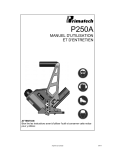
1
MICRO PRODUCTS COMPANY
MANUFACTURERS OF
PRECISION WELDING MACHINES
J3, J4 BUTT WELDERS
SERVICE MANUAL
1
TABLE OF CONTENTS
1.0
2.0
3.0
4.0
5.0
6.0
7.0
8.0
9.0
10.0
11.0
12.0
13.0
SPECIFICATIONS
GENERAL HOOK-UP INSTRUCTIONS
GENERAL OPERATING INSTRUCTIONS
SUGGESTED SETTINGS
TYPICAL OPERATING SEQUENCE
ANNEALING INFORMATION
SPECIAL ADJUSTMENTS
PREVENTATIVE MAINTENANCE
DIAGNOSTIC CHART FOR TROUBLE-SHOOTING
ELECTRICAL SCHEMATIC
SAFETY REMINDERS
BUYERS GUIDE
PARTS LIST
1.0
SPECIFICATIONS
Stock Size
Range,
Diameter
Material
Standard
Operating
Voltages
Input Power
Cycle
Line Demand,
115 volts *
Line Demand
230 volts *
Heat
Selection
Switch
w/high-low
Range Switch
50% duty
cycle rating
DIMENSIONS
AND WEIGHTS
4-Wheel Truck
Mounted
Floor Space
Welding Die
Height
Height
Overall
Welder Weight
Model J3C
.032” to
.064”
(.81mm1.588mm)
Model J4C
.064” to
.128”
(1.62mm3.25mm)
Model J3S
.020” to
.080”
(.51mm-2mm)
Model J4S
.040” to
.160”
(1mm-4mm)
Copper & EC
Aluminum
Copper & EC
Aluminum
Steel, Alloy,
Stainless
Steel, Alloy,
Stainless
Model J4Sf
.004” sq to
.030” Sq
(2.58mmsq. to
19.35mmsq)
Cross
sectional
Steel, Alloy,
Stainless
230 Volts
115 Volts
230 Volts
115 Volts
230 Volts
115 Volts
230 Volts
115 Volts
230 Volts
115 Volts
60
24
77
12
38
60
24
77
12
38
60
9
29
5
15
60
9
29
5
15
60
24
77
12
38
Hertz
amps@100%
amps@10%
amps@100%
amps@10%
Hertz
amps@100%
amps@10%
amps@100%
amps@10%
Hertz
amps@100%
amps@10%
amps@100%
amps@10%
Hertz
amps@100%
amps@10%
amps@100%
amps@10%
Hertz
amps@100%
amps@10%
amps@100%
amps@10%
4 Point
4 Point
10 Point
10 Point
4 Point
4 KVA
4 KVA
1.5 KVA
1.5 KVA
4 KVA
2 Stationary
Casters 2
Swivel
Casters
24” x 24”
(61cm x 61cm)
2 Stationary
Casters 2
Swivel
Casters
24” x 24”
(61cm x 61cm)
2 Stationary
Casters 2
Swivel
Casters
24” x 24”
(61cm x 61cm)
2 Stationary
Casters 2
Swivel
Casters
24” x 24”
(61cm x 61cm)
2 Stationary
Casters 2
Swivel
Casters
24” x 24”
(61cm x 61cm)
41” (104cm)
53-1/2”
(136cm)
180Lbs(82 Kg)
41”(104cm)
53-1/2”
(136cm)
180Lbs(82 Kg)
41”(104cm)
53-1/2”
(136cm)
180LBs(82 Kg)
41”(104cm)
53-1/2”
(136cm)
180Lbs(82 Kg)
41”(104cm)
53-1/2”
(136cm)
180lbs(82 Kg)
* Other voltages available
2
2.0
GENERAL HOOK-UP INSTRUCTIONS
2.1
ELECTRICAL
First Determine that available electrical service in your
plant corresponds to the nameplate rating located on the
welder housing. Electrical wiring to the welder must be of
sufficient size to deliver full ampere load with no
appreciable loss during the weld cycle. The welder will not
operate properly if there is more than a 10% variation in
the line voltages. In general, the welder should be fused
with a slow blow fuse of the 100% duty cycle rating. The
minimum power cable size to the welder can be obtained
by using this same current rating.
Refer to the National Electric Code and local electrical
regulations for adequate power sizes; disconnect methods,
and fusing guidelines.
Remember, line voltages to the welding machine are
potentially dangerous should the power cords be damaged or
severed. The welding voltages at the welding dies will not
harm an operator, since they do not exceed 5 volts.
2.2
SAFETY PRECAUTIONS
2.2.1 ELECTRICAL
Maintain electrical cable to welder in good repair. Welder
must be grounded and connections securely tightened. Heat
switch must not be changed to new position while a weld
cycle is in process. Disconnect electrical service before
servicing welder – high voltages are located within the
base of the welder.
2.2.2 MECHANICAL
Safety glasses must be worn by operator while using welder.
Keep all safety guards on welders and use properly.
Operators must be instructed on basic operation of unit to
prevent injury. Check nameplate rating and keep within
material size range for each welder.
3
2.3
WATER
It is important that if a welder is to be operated for an
extended period of time and headpieces heat up, water lines
must be connected. On most model J series Micro-Weld
welders, water-cooled headpieces are an option, which can
be added at our factor. Connect hoses to inlet and outlet
provided at the back of the welder. A shut-off should be
installed in the inlet line, and the hose from the outlet
should run to an open sight drain. Water should only flow
during the weld cycle and the temperature of the water at
the drain should feel hot to the hand. This will prevent
condensation on the welder headpieces, which could drip on
the welding transformer and cause it to ground out.
2.4
AIR
Air operated model J series Micro-Weld welders are an
option. Should you have this option, air operation
cylinders require a 90 P.S.I. air source. An air regulator
will be provided to set the minimum amount of pressure
needed for the material being welded.
4
3.0
GENERAL OPERATING INSTRUCTIONS
BASIC OPERATING PARTS
3.1
WELD HEAT SELECTION
This setting determines the amount of heat available for
welding. Because of considerable variations in voltage and
power factors in various plants, and wide variety in
material composition, exact heat setting cannot be
specified. In general, larger sizes of stock use higher
heat settings.
Welding heat is selected by means of a heavy-duty switch
and, on some models, a high-low range switch. See tale 1.
The heat switch is conveniently located on the left side of
the welder. Number 1 indicates high heat, number 4 or 10
indicates low welding heat. Other numbers are equally
graduated from high to low to allow just the right amount
of voltage for the welding operation. On models with the
high-low range switch, it is located on the front right,
just below the nameplate. The range switch sets the range
of the heat switch with the low range settings picking up
where the high range settings leave off.
The heat or range switch should never be changed to a new
setting during a welding operation.
Table 1
Model
J3C
J3S
J4C
J4S
J4SF
3.2
Heat Switch
Settings
4
10
4
10
4
H/L
Range
Yes
Yes
Yes
Yes
No
SPACING MECHANISM
The welder is capable of welding a variety of material
sizes, but each major change in material size requires a
corresponding change in the open space of the jaws.
Spacing is obtained by rotating the space-adjusting knob
located on the lower right side of the headpiece housing.
The spacing knob determines the amount of weld upset and
expelled metal projecting from the weld zone.
5
3.3
UPSET PRESSURE MECHANISM
Upset pressures are required for all weld operations. The
model J series of Micro-Weld welders obtains its pressures
form unique spring assemblies located on the clamp arms.
The upset pressures are completely adjustable for various
sizes and types of materials. Adjustment of the clamp
spring pull determines the amount of upset pressure for the
weld forging process. This is obtained by adjusting the
length of the pull bar by rotating the tension disc on the
foot pedal assembly. Number 1 denotes the greatest upset
pressure.
3.4
FLASH SPEED MECHANISM
On model J4SF welder, precise flashing speed regulation and
final upset drop off is obtained from its unique hydraulic
cylinder located on the right of the weld head. Flashing
speed is set with the use of the flashing speed adjusting
knob, which regulates the speed of the oil passing the
internal valve. Number 1 indicates the slowest flashing
speed. Turn the knob counterclockwise to increase the
flashing speed. Generally, larger stock requires a slower
flashing speed. Final upset is obtained when the piston is
compressed to a point where the internal valve is bypassed
allowing unrestricted movement. This bypass point can be
adjusted by rotating the piston cap clockwise causing the
unrestricted movement of the piston to begin when the
welding dies are closer together. Properly made welds are
perfectly sound and have little upset burr. Poor welds
usually indicate too low heat or incorrect flashing speeds.
3.5
WELDING DIES AND DIE SHOES
Welding dies serve three purposes: (1) to carry current and
voltages for welding, (2) to align material ends, and (3)
to prevent slippage during the weld cycle. Small wire must
be placed into small grooves and large wire into the large
grooves. Flat stock must be placed against the stop in the
rear of the dies. The die shoe holds the material securely
into the lower welding die during the weld process.
3.6
HAND SHEAR
An accessory hand shear may be affixed to welder to assist
in trimming waste materials prior to welding. Several
types are available from Micro Products Company.
6
3.7
FILING VISE
Accessory machinist vises or special Micro-Weld vises are
available to assist the operators to hold wire during deburring operations.
3.8
ANNEALING DEVICES
Three types of annealing devices are available to assist in
processing weld zones, which may have become brittle during
the weld cycle. They are: (a) Standard anneal, used on
non-ferrous types of material or on low carbon steel wire.
(b) Front anneal, used on low, mild steel applications, and
(c) dial indicating anneal, used on high carbon steel wire.
3.9
FOOT TREADLE MECHANSIM
The model J series Micro-Weld wire and rod welders are
activated by using a foot treadle device, which performs
the welding sequence. The manual foot treadle may be
replaced with an air-activated mechanism so that the
operator just has to move his foot slightly to activate the
weld process. Some welding advantage is gained in weld
quality by using the air-upset mechanism since all
activating strokes are exactly the same.
All operations on the Micro-Weld model J series, wire and
rod welders are performed by a single down-stroke of the
treadle mechanism, when the treadle is released, the
operating parts are automatically re-spaced, ready for the
next weld operating.
Blind guides can be designed for handicapped people.
7
4.0
SUGGESTED SETTINGS
Size
J4SF Welder
(flat stock)
.021” x .275”
.042” x .514"
Stock
Oil
Cylinder
Space
Heat
Tension
Steel
Steel
7
4
7
9
4
2
1
1
APPROXIMATE SETTINGS TO AID IN OBTAINING HIGH QUALTY WELDS
Stock
Steel
Copper
Steel
Copper
Size
.020”
.050”
.080”
.032”
.040”
.050”
.064”
.040”
.060”
.080”
.100”
.160”
.128”
.102”
.080”
.064”
Heat
6
4
1
4
3
2
1
10
8
6
4
1
1
2
3
4
Space
5
7
9
3
4
5
6
3
4
5
6
9
9
7
6
5
Grooves
Front
Middle
Rear
Front
Middle
Middle
Rear
Front
Middle
Middle
Rear
Rear
Rear
Rear
Rear
Middle
Tension
1
1
1
3
3
3
3
3
3
3
1
1
1
1
1
3
Range
Low
Low
Low
Low
Low
Low
Low
High
High
High
High
High
High
High
High
High
Type
Welder
J3S
J3C
J4S
J4C
Welders used for E.C. aluminum may use approximately the same
settings as copper.
8
5.0
TYPICAL OPERATING SEQUENCE
J3C, J4C & J3S, J4S
Remember: Material to be joined must be free of rust,
corrosion, or other insulating material where it contacts
welding dies.
1. Cut wire ends to best joint configuration. See figure 1.
2. Set open space for proper die opening.
3. Select proper weld heat and range.
4. Place wire into welding dies so the ends touch midway
between the welding dies.
5. Push foot treadle down far enough to hold material in
place in dies.
6. Close flashguard.
7. Push foot treadle down to bottom of stroke to finish
clamp process and start weld process.
8. Heat is imparted to wire ends through faying surfaces.
9. Movable platen, under upset pressures, moves toward a
closed position due to loss of compression yield
strength of wire.
10. A weld limit switch terminates electrical power flow
through wire.
11. Actual weld is formed after electric power flow stops,
and material is hot forged together with remaining upset
pressure.
12. Welded material quickly cools under pressure.
13. Remove stock from dies by releasing foot treadle.
14. Anneal weld zone and sections on either side, if
applicable.
15. Remove upset burr so the enlarged weld area is equal in
diameter to the parent metal size.
9
J4SF
1. Cut material ends to best joint configuration. See
Figure 2.
2. Set open space for proper die opening.
3. Set flashing speed
4. Select proper weld heat.
5. Place material into weld dies so the ends touch midway
between the welding dies; also, flat stock should be
against the rear stops in the dies.
6. Push foot treadle down far enough to hold material in
place in dies.
7. Close flashguard.
8. Push foot treadle down to bottom of stroke to finish the
clamping process, and start weld process.
9. Heat is imparted to the material end through faying
surfaces.
10. High current flow causes flashing
11. Movable platen, under controlled speed and pressure,
moves toward a closed position, due to flashing, until
the faying surfaces are covered with molten metal, and a
short length of each part reaches forging temperature.
12. When the movable platen reaches a preset point, flashing
speed is terminated, and upset pressure is applied.
13. Further movable platen travel then activates the weld
limit switch, and electrical power flow through the
material is terminated.
14. Actual weld is formed after electric power flow stops,
and material is hot forged together with remaining upset
pressure.
15. Welded material quickly cools under pressure.
16. Remove stock from dies by releasing foot treadle.
17. Anneal weld zone and sections on either side, if
applicable.
18. Remove upset burr so as the enlarged weld area is equal
to the parent metal size.
10
Examples of good welds (picture)
11
5.1
ANNEALING INFORMATION
An anneal operation will be required on hard drawn or
carbon steel wire and rod. Annealing will accomplish tow
things: (1) normalize the grain structure in the weld zone,
(2) will soften sections on either side of the immediate
weld area.
To anneal, follow directions of one of the following
methods, which is applicable to your welder.
5.2
STANDARD TYPE ANNEAL DEVICE
With standard type anneal device cam anneal clamps attached
directly to movable and stationary welding platens with “L”
shaped brackets or similar devices. Used on welders
suitable for welding non-ferrous and low carbon steel wire
and rod.
A. Close safety flashguard if equipped with
interlocking switch.
B. Place welded stock into anneal clamps with upset
burr midway between anneal clamps, clamp securely
into position.
C. Push annealing switch with a jogging action to heat
material to desired temperature.
D. After the material has lost its color, carefully
remove the wire from the anneal jaws and remove the
upset burr. Be extremely careful not to get burned
on the hot metal.
5.3
FRONT OR DIAL INDICATING ANNEAL DEVICES
A cam type clamp anneal located beneath the welding dies.
One clamp is stationary and the other is movable clamp
which is attached to a unique mechanism which allows the
hot, expanding and annealing wire to remain straight
without the normal bowing or bending. This feature assists
in preventing fractures in weld zone during anneal process.
Both type of devices, front or dial type, are suitable for
low carbon steel, mild steel, stainless steel and high
carbon steel.
12
5.4
FRONT TYPE ANNEAL, OPERATING PROCEDURES
A. Close safety flashguard, if so equipped.
B. Place welded stock into anneal clamps with upset burr
midway between anneal jaws, being careful to push
movable clamp jaw against its inward stop. Carefully
tighten wire into both jaws.
C. Push anneal switch in a jogging fashion, to evenly heat
up weld area to desired anneal temperature.
D. Let annealed are cool.
E. After the wire has lost its color, carefully remove the
wire from the anneal jaws and remove the upset burr.
F. Be careful not to get burned on the hot metal.
5.5
DIAL INDICATING ANNEAL DEVICE OPERATING PROCEDURES
A. Proceed as instructed on front type anneal and proceed
with the following information.
B. When heat is applied to the wire, the heated wire will
expand.
C. The dial indicator will start to move as the wire begins
to heat up.
D. When the exact anneal temperature is reached, the
rotating needle on the dial indicating device will
momentarily stop.
E. In sequence, the needle will drop back slightly, and
then start to move forward again.
F. At the start of the second forward movement of the
needle, release the anneal switch.
G. Heating the wire beyond this pint, will cause an
improperly treated anneal zone.
H. Allow wire to cool down below 1000 degrees F., before
removing wire from the anneal clamps. (Loss of coloring
to wire)
I. Be extremely careful of hot metal during handling
procedures.
13
5.6
DETERMINING CORRECT ANNEAL TEMPERATURES
The critical temperature of carbon steel wire is also the
maximum heating temperature for the annealing process
associated with the butt-welding procedures. The critical
temperature will vary slightly, but in direct proportion to
the wire’s carbon content. Since carbon steel is
ferromagnetic, the exact annealing temperature can be
easily determined by the loss of magnetic qualities at that
point.
To expand this process further, a wire that is gradually
heated to a point of just beginning to show some color is
very close to the correct anneal temperature (about 1000
degrees F). At this point, the jogging off-on of the
anneal switch is important, so that when we test the
annealing area with a magnet during the off period it will
not be drawn to the wire surface due to electrical magnetic
flux. When the magnet does not attach to the wire surface,
the correct anneal temperature has been achieved. We are
looking for the exact point of loss of magnetic qualities,
so do not over heat the material beyond this point.
Annealing after welding to enable an operator to draw
carbon steel wire is very important for the wire mill and
certain techniques have been developed by others which may
assist in drawing high carbon steel wire. Possibly the
methods described here will be beneficial to your
operation.
5.7
ANNEALING ALUMINUM WIRE AND ROD
Annealing aluminum rod and wire can be somewhat difficult
since it passes very quickly through the plastic rang and
blows apart. Be extremely careful not to get burned from
expelled aluminum by poor safety techniques.
A good anneal temperature for aluminum rod and wire is
approximately 700 degrees F. Common blue carpenters chalk
rubbed on the surface to be annealed will assist in
obtaining this temperature. The chalk will turn a straw
color at the anneal temperature 700 degrees F.
14
6.0
SPECIAL ADJUSTMENTS
HEADPIECES
Refer to Figures 4 through 7
6.1
SPACE ADJUSTING KNOB
Determines the amount of open space between the welding
dies.
Calibration:
1. Turn space-adjusting knob to the stop or the number
1 setting.
2. Lay a straight edge across the die seats.
3. The die seats should be level and the weld dies
should have 1/32” between the closest die edges.
4. If die seats are not level:
A. Back headpiece close stop screw off of nylon
stop pad.
B. Loosen the setscrew on the space-adjusting knob.
C. With a pair of pliers, turn the space-adjusting
shaft until dies are level and proper clearance
between dies exists.
D. Retighten spacing knob so that the arrow pointer
is across from #1.
5. A compression spring and stop pin are located
beneath the spacing knob to assure repeatable
positions and overthrow protection. Check to make
sure spacing knob has pressure applied to it from
this spring and pin is not bent or missing hence
preventing proper adjustment, replace as required.
6.2
HEADPIECE CLOSED ADJUSTMENT
Prevents welding dies from touching, and prevents possible
over travel of movable platen.
Calibration:
1. Turn space-adjusting knob to the stop at the number
1 setting.
2. Adjust closed stop adjusting screw so that when the
movable head is pushed by hand, to a closed
position, the weld dies will not touch, and there
is approximately 1/64” at #1 setting.
3. Tighten locknut.
15
6.3
WELD LIMIT SWITCH
Determines the timing point of the weld cycle.
Adjustments:
1. The limit switch is adjusted for actuation by a
hex-head bolt, which contacts the limit switch
plunger. The weld dies will be used as a reference
point to obtain the adjustment.
2. Loosen the limit switch adjusting screw locknut.
3. Set open space adjusting knob to approximate #4.
4. Slowly turn space-adjusting knob clockwise toward
#1 until the hex-head bolt activates the limit
switch.
5. There should be 1/16” between the closest die
edges.
6. If the gap is greater than this screw bolt in to
activate the switch later. If the gap is less than
1/16” then screw the bolt out to activate the
switch sooner. Repeat steps 3 and 4 after making
bolt adjustments until step 5 is achieved.
7. Tighten locknut.
8. The limit switch remains the same for all wire
sizes, but can be used for a vernier control of
heat in extreme cases to add or subtract slight
amounts of heat to assure levelness of welded
material.
Figures 4-5-6-7-8-9-9A-10
16
17
18
19
6.4
HYDRAULIC CYLINDER
Refer to Figures 8. For new type cylinder see addendum.
CONTROLS THE FLASHING SPEED AND UPSET POSITION
Calibration:
1. Set closed stop adjusting screw to stop movable
head when dies are 1/32” between closest die edges.
2. To set unrestricted movement of hydraulic cylinder
to begin when dies are 3/32” apart;
A. If unrestricted movement starts at a greater
distance:
1. Loosen lock nut on piston cap.
2. Rotate cap clockwise to make unrestricted
movement of piston to begin when welding
dies are closer together.
3. Tighten locknut on piston cap.
B. If unrestricted movement starts at a lesser
distance:
1. Loosen lock nut on piston cap.
2. Rotate cap counterclockwise to make
unrestricted movement of piston begin when
welding dies are further apart.
3. Tighten lock nut on piston cap.
3. Set limit switch to cut-off weld current 1/32”
after unrestricted movement has begun.
6.5
CLAMP SPRING AND UPSET PRESSURES
Refer to Figure 9
UPSET PRESSURE
Determines the amount of clamping and upset pressure
available for weld process, by making pull bar longer or
shorter.
Calibration:
1. With nothing in welding dies, depress foot treadle.
2. With a straight edge, determine that bolts A,B,C
and D are all in alignment. Lengthen or shorten
pull bar to attain this setting. This alignment
sets the welder for maximum pressures.
3. Should you require lesser pressures for smaller
wire sizes, the pull bar can be lengthened to
decrease pressure as per the following:
(See figure 9A)
A. Loosen hand wheel on the foot pedal assembly.
B. Rotate disc so number on disc lines up with
notch on back-up plate.
C. Tighten hand wheel.
4. Lesser pressures are indicated when center bolts; B
and C are above the centerline.
20
5. Do not shorten the pull bar to such a position so
that the center bolts B and c are below the
centerline. Clamp spring breakage could occur.
6. Pressures should not be increased or decreased by
cross bolt adjustments.
Important: Do not turn or remove the front center pivot
screw and nut. To remove the movable half of the weld head
as specified in the preventive maintenance techniques,
loosen and remove the rear center pivot only.
6.6
CLAMP SPRING CROSS BOLT
Refer to Figure 10
Assures maximum die shoe opening and non-shorting of weld
head when annealing.
Calibration:
1. Adjust cross bolt on clap arm on the stationary head
to where the clamp arm just contacts the weld die seat
and approximately 1/16” to 1/8” clearance is evident
between the clamp spring clevis and weld die seat.
2. Adjust cross bolt on clamp arm on the movable head to
where the clamp arm just contacts the weld die seat.
3. Tighten lock nuts.
21
7.0
PREVENTATIVE MAINTENANCE
Keep in mind that these welders are precision built to last
many years, but will require good maintenance procedures.
They are designed to be as automatic as possible with a
minimum dependence on the ability of the operator.
Adjustments must be made by those thoroughly familiar with
the operating principles of the welders.
7.1
AS REQUIRED
1. Remove flashings and loose particles from welding
headpieces to prevent accumulation. Use a soft brush
and a soft metal scraper.
2. Check condition of welding dies and welding die shoes,
replace as required.
3. Check condition of clamp spring assemblies and replace
all broken springs, springs that have taken a set as
well as worn fiber bushings and washers.
7.2
QUARTERLY
1. Repeat above items.
2. Check anneal dies and replace all worn parts.
3. Check for worn bearings and elongated holes on foot
treadle assemble and pull rod parts.
4. General lubrication of all moving parts.
7.3
ANNUALLY
1. Repeat above noted items.
2. Check for worn or poorly aligned contacts within
magnetic contactor. (Some older Model J3 and J4 series
units do not have contactors.)
3. Clean weld transformer secondary strap connects to
movable headpiece. Emery cloth works well to bring all
surfaces in this area to a bright and shiny condition.
Retighten completely.
4. Check for excessive wear in clamp arm assemblies, where
die shoes fit into clamp arm openings. Replace as
required.
5. Remove movable welding headpiece by loosening rear pivot
centers. Check the condition of the pivot center
surfaces, polish and thoroughly clean. Re-lubricate and
re-install movable headpiece and adjust so that the
movable headpiece do not have any side play. Headpiece
must be free to pivot and die seat surfaces must be in
good alignment.
6. Check headpiece castings, if worn, replace. Should the
welders be used in a corrosive atmosphere, clean off
oxides and repaint as required.
22
8.0
WELDING DIES AND DIE SHOES INFORMATION
Description:
Welding dies – Lower conducting electrode and clamp jaw
Weld die shoes – Upper clamping member
Welding dies and die shoes in poor condition are the main
causes of bad welds.
Care of die sets:
1. Use a brass or fiber blade to remove particles of
flashings that build-up on die sets. Excessive flash
build-up causes die burns on material and shorting of
die sets.
2. Do not attempt to clamp material that is not suited for
welder into die sets. Undersized materials will slip
and burn die grooves. Oversized materials will
overstress clamping parts.
3. Do not use welding die sets for a vise. These parts
will not withstand the mechanical abuse.
4. Whenever welding dies are replaced, clean bottoms of
dies and corresponding die seats to a bright and clean
condition before bolting them tightly into place and
oxidize surface will insulate the welding dies and
reduce effective welding voltage.
5. Welding die shoes must swivel freely within the clamp
arm pivots to prevent cracking of die shoes. File down
die shoe boss if necessary.
6. Welding die set will wear with use and must be changed
occasionally for good welding results. Keep an adequate
supply of replacement parts available. Wire and rod
slippage is a problem caused by poor die sets and a
major cause of wire breaks.
Types of welding die shoes picture
23
9.0 DIAGNOSTIC CHART FOR TROUBLE-SHOOTING
WELDING ACTION
Weld action normal but weld
burr doesn’t extend beyond
wire
Molten metal is blown out
and ends not joined
Weld area heats up but weld
is not complete
Weld has complete burr but
is dry and breaks off below
surface of wire
CAUSE
REMEDY
Lack of open space
Increase open space until
desired burr is obtained
Lower heat settings
Set limit switch properly
Check size rating of welder
Replace clamp springs
Increase weld heat
Clean and tighten
transformer connections
Clean welding dies and
surfaces
Decrease starting space
Lower upset pressure
Reset limit switch to
specifications
Carbon-steel wire often
appears like this, process
wire by annealing weld
before removing burr
Replace worn dies and shoes
Decrease starting space
Return heads to factory
Decrease upset pressure
Increase weld heat
Worn dies and shoes
Check electric lines
Clean and tighten
transformer connections to
heads
Clean rod where clamped in
dies
Replace dies and shoes
Clean build-up of flash
materials
Weld heat too high
Weld limit switch
Stock is too small
Weak clamp spring
Low heat
Secondary transformer
connections
Loose or dirty welding dies
Starting space adjust
Upset pressure too great
Limit switch settings
High carbon steel wire
Welds good but poorly
aligned
Ends of wire buckle and may
not weld
Varying weld results
Welding dies & die shoes
Starting space
Loose pivot centers
Upset pressure too great
Low weld heat
Stock slipping
Varying weld voltages
Rod condition variations
Dies and die shoes
Flashings
Rod cuts
Weld contactor
Check contactor for poor
contacts
24
9.1
ELECTRICAL TROUBLE-SHOOTING OF WELDER
(Caution!! Extreme care should be exercised when making
these tests. Dangerous voltages are present in the welder.
Only persons familiar with electrical safety precautions
should perform these tests.)
9.1.1 TROUBLE-SHOOTING TABLE
(see section 9.1.3 and 9.1.4)
This electrical trouble-shooting table is furnished as a
suggested method of trouble-shooting the welder. The
individual steps of the table should be performed in the
order given, to make the test valid. The electrical
schematic (section 10) furnished for these tests shows the
table test points. This table may be used for welders with
a different but closely related wiring by using
corresponding test points. During all tests, line voltage
should be connected to L1 & L2 of the welder. The heat
switch should be set to the #1 position.
9.1.2 FINAL ELECTRICAL CHECKS
Set the heat switch to the number 1 position, connect the
voltmeter across the welding dies. Press the operating
switch. The meter reading will typically be less than 10
VAC. Consult the weld specification sheet for this value.
Rotate the heat switch through all settings. If the
voltage is not read at any setting, the heat switch may be
defective. Actuate the weld limit switch; observe the
reading goes to zero. Release the weld limit and operating
switches, the reading should remain at zero.
25
9.1.3 MODEL J3 & J4 - 115 VOLT TABLE – Use Schematic B3275B
TEST LEAD
CONNECTION
L2 FU1-1
L2 FU1-2
METER
READING
115 VAC
115 VAC
L2
L2
L2
L2
FS1-1
FS1-2
FS2-1
FS2-2
115
115
115
115
L2
L2
L2
L2
L2
L2
LS1-1
LS1-2
CR1-1
CR1-2
S1-1
CR2-2
VAC
VAC
VAC
VAC
115 VAC
115 VAC
Line voltage
Line voltage
Line voltage
Line voltage
PROBLEM
IF NO
READING
Bad fuse connection
Open fuse
Open wire to operating
switch
Bad operating switch
Open wire to anneal switch
Open anneal switch
Open wire to weld limit
switch
Bad weld limit switch
Open wiring to contactor
Bad contactor
Open wire to heat switch
Bad contactor
PRESS
OPERATING
SWITCH
WELD LIMIT
SWITCH
ACTUATED
PRESS
ANNEAL
SWITCH
X
X
X
X
X
X
X
9.1.4 MODEL J3 & J4 – 230 VOLT TABLE – Use Schematic B5741A
X1 X2
X2 FU1-1
X2 FU1-2
115 VAC
115 VAC
115 VAC
X2
X2
X2
X2
115
115
115
115
X2
X2
L2
L2
L2
L2
FS1-1
FS1-2
FS2-1
FS2-2
LS1-1
LS1-2
CR1-1
CR1-2
S1-1
CR2-2
VAC
VAC
VAC
VAC
115 VAC
115 VAC
Line voltage
Line voltage
Line voltage
Line voltage
Bad control transformer(T2)
Bad fuses connection
Open fuse
Open wire to operating
switch
Bad operating switch
Open wire to anneal switch
Open anneal switch
Open wire to weld limit
switch
Bad weld limit switch
Open wiring to contactor
Bad contactor
Open wire to heat switch
Bad contactor
X
X
X
X
X
X
X
Note: to perform repairs consult section 13 for parts
identification
26
10.0 ELECTRICAL SCHEMATIC
27
11.0 SAFETY REMINDERS
The following accident prevention information is presented
to eliminate potential hazards while operating, inspecting
or repairing Micro-Weld electric resistance welding
equipment.
Important safety compliance information for Micro-Weld
Welders.
GENERAL
1. Prior to using equipment, an operator must be instructed
on basic operation and malfunction methods, by qualified
personnel.
2. Safety eyeglasses must be worn by all personnel
operating or servicing welders.
3. Use safety equipment properly and keep safety equipment
on welders.
4. Determine that both operating voltages and hertz
(cycles) of power supply correspond to ratings listed on
weld nameplate located on weld housing.
5. Check nameplate ratings and keep within capacities and
material categories stated therein.
6. Adjustment or repairs must be made by persons thoroughly
familiar with operating principles of welder.
7. Welder must be disconnected from power supply prior to
maintenance or repair procedures.
8. Reduce air supply pressures or disconnect from air
source, for pneumatically equipped welders, prior to
maintenance or repair procedures.
9. Welders equipped with water cooling accessories must
have water supply turned off during idle periods and
allow only enough water to flow to cool heated
components during weld operation.
28
ELECTRICAL
1. Refer to National Electrical Code and local regulations
for adequate electrical wiring to power welder. Do not
operate welder with inadequate electrical power supply
cords or cable.
2. All welders must be ground through power supply and
welder ground connection terminal securely tightened.
3. All welders must be able to be disconnected from power
source either by a double breaking disconnect switch or
unplugged by standard rated plugs.
4. All welders must be fused to prevent injury should an
electrical malfunction occur. Welders must never be
fused for an ampere load that exceeds the ratings stated
on weld nameplate. Normally welders are fused using the
nameplate rated load; time lag parameters functional to
standard fuses allow this specification.
5. Electric power cords to welder must be kept in good
condition. Report any damage or potential hazards to
maintenance personnel.
6. The weld heat selection switch, potentiometer or range
selection devices must not be changed to a new position
while a weld operating is in process.
29
12.0 BUYERS GUIDE
HOW TO ORDER PARTS:
You must provide
1. Machine Model
2. Machine Serial Number
3. Voltage
Then identify part(s) on part list (last page in book) and
provide MICRO with the circled number
CALL MICRO at 800-872-1068
Provide MICRO with your company name, address and purchase
order number.
30
31
32
33
13.0 PARTS LIST
Butt Welders J3, J4
Model/
Part No
J4-01
J4-01A
J4-08R
J4-08L
J4-10
J4-11
J4-18A
J4-21
J4-22
J4-23
J4-24
J4-25
J4-26
J4-27
J4-28
J4-30
J4-12
J4-13
J4-14
J4-14C
J4-15
J4-16
J4-17
J4-19
J4-03S
J4-03C
J4-04
J4-04A
J4-05
J4-06
Description
Headpiece stationary and movable
Match machined w/adjustable centers
Headpiece assembly complete w/all
Operating parts, state model & serial
Number
Clamp arm, standard, right
Clamp arm, standard, left
Clamp arm retaining screw
Clamp arm retaining screw washer
Weld transformer strap insulator
Space adjusting knob
Space adjusting screw
Space knob tension spring
Return spring, movable head
Return spring, insulating bushing,
2 required
Headpiece closed, adjusting screw and
Nut
Headpiece closed, adjusting screw
Insulated stop
Center, adjusting, rear
Center adjusting, front
Clamp spring retaining pin and key, outer
Clamp spring insulating washers, 4 req’d
Clamp spring standard, 1/16”
Clamp spring assembly with all
Operating parts
Clamp spring metal bushing
2 required, inner
Clamp spring fiber bushing,
2 required, outer
Clamp spring cross bolt, nuts and
Washer set
Clamp spring attaching bolt, inner
Welding transformer, steel
Specify: 120 or 240 volts, 60 hertz
Welding transformer, copper or
Aluminum, 240volts, 60 hertz
Heavy-duty step-down transformer,
Specify line and welder voltages
Step-down transformer mounting plate
Welding transformer secondary clamp plate
Clamp plate attaching screw, 2 req’d
Item #
32584
32585
32517
32518
93081
92706
37710
32553
32502
80037
80021
32504
90250
32503
32515
32516
93100
92904
80017
32507
85055
85055
32609
42504
42582
42642
90605
34
Model/
Part No
J4-07
J4-184
J4-185
J4-186
J4-92A
J4-138A
J4-138B
J4-139A
J4-140A
J4-105A
J4-106A
J4-105A
J4-106A
J4-105L
J4-120
J4-121
J4-58C
J4-58M
J4-58E
J4-59
J4-60S
J4-60SA
J4-60SB
J4-60B
J4-20A
J4-30A
J4-30B
J4-31
J4-32
J4-33
J4-35
J4-36L
J4-36R
J4-37
J4-38
J4-39
J4-44
J4-45
J4-46
J4-47
J4-51
J4-52
Description
Screw, secondary strap attaching,
Stationary head
Control circuits, step-down transformer
Contactor, welding, 25 ampere
Relay, anneal circuits, 15 amperes
High-off-low heavy-duty switch
Heat switch, 10 point type, 25 ampere
Heat switch, 4 point type, 25 ampere
Heat switch knob for 25 ampere switch
Heat switch housing for 25 ampere
Switch, specify: 4 point or 10 point
Operating switch short stem
Operating switch housing
Anneal switch, short stem
Operating switch housing
Limit switch, long stem
Limit switch cover w/attaching screws
Limit switch adjusting screw & locknut
Welding dies, pair, copper
Welding dies, pair, copper alloy, class #2
Welding dies, pair, copper alloy, class #4
Welding die attaching screw, 2 required
Welding die shoes, upper, pair, steel face
Affixed
Replacement serrated steel face, each
Rivets, steel faced per (100) pieces
Welding die shoes, upper, bronze
Anneal frame-mounting screws, set
Bearing center, adjustable, front or rear
Nylon center insulator
Anneal frame, stationary
Anneal frame, movable
Anneal frame, power shunt cable
Anneal frame, space-adjusting screw set
Anneal die carrier bracket, left hand,
Top anneal
Anneal die carrier bracket, right hand,
Top anneal
Anneal die carrier bracket, slide type,
Front anneal
Slide bracket adjusting knob, screw/nut
Shunt cable lug
Anneal block, flat, pair
Anneal attaching screw, 2 required
Anneal die shoe, each, 2 required
Anneal die shoe, pivot mounting stud
Handle, anneal clamping
Eccentric carrier strap and nut
Item #
90605
57601
57613
57660
57843
57802
57801
48215
32524
57810
32523
57810
32523
59084
32586
90252
32530
32531
32532
90603
32534
32533
93051
32535
32614
62046
37713
62055
62065
62157
32610
62053
62054
62107
62101
86171
32525
90603
62062
62059
62063
62060
35
Model/
Part no.
J4-53
J4-53A
J4-54
J4-61
J4-62
J4-200
J4-201
J4-172S
J4-172R
J4-172W
J4-173
J4-174A
J4-175
J4-178
J4-180
J4-181
J4-182
J4-183
J4-187
J4-151
J4-152
J4-153
J4-154
J4-155
J4-156
J4-84C
J4-86
J4-87
J4-68A
J4-68C
J4-68
J4-69
J4-71
J4-131C
J4-131
J4-132
J4-133
J4-134
J4-135
J4-136
J4-09R
J4-09L
J4-14F
Description
Item #
Eccentric, anneal clamping
Pin, eccentric attaching
Spring, anneal clamping
Dial indicator assembly
Dial indicator contact button
Complete front anneal device with
Dial indicator
Complete front anneal device less dial
Caster, swivel
Caster, rigid
Wheel only, 5”
Return spring, anneal or operating
Switch levers
Pedal, operating lever
Plunger, operating switch lever
Plunger, anneal switch lever
Pull bar with clevis
Pull bar tension adjusting disc
Pull bar attaching screw
Pull bar adjusting knob
Foot pedal return spring, new style
Extension type
ETS wire shear, stationary housing
ETS wire shear, movable housing
ETS wire shear, handle
ETS wire shear, cutter, pair
ETS wire shear, pivot bolt and nut
ETS wire shear, complete
Lamp complete
Lamp, 25 or 40 watt standard base
Lamp receptacle
Flashguard, O.S.
Flash guard complete, o.s.
Flash guard flap,o.s.
Flash guard mounting bracket, o.s.
Flash guard attaching bolt and washer
Filing vise complete
Filing vise, movable half
Filing vise, stationary half
Filing vise, handle
Filing vise, sliding block
Filing vise, spring
Filing vise, cap screw and nut
Clamp arm, special for hand clamp type,
Right
Clamp arm, special for hand clamp type,
Left
Clamp spring, special 3/32” thickness,
Also used for hand clamp
62061
92602
80022
77851
62012
62168
62067
48100
48101
80049
42563
42576
42576
42626
42503
90233
42578
64013
64006
64008
64043
90624
64007
52539
58151
58166
42506
90601
60009
60013
60012
60007
60008
80024
90300
32511
32510
80019
36
Model/
Part No.
J4-55
J4-56
J4-57
J4-58EA
J4-58EB
J4-58EC
J4-225A
J4-226C
J4-226D
J4-226E
J4-228A
J4-232
J4-233
J4-234
J4-235
J4-236
J4-90A
J4-102
J4-103
J4-104
J4-122
J4-123
J4-S80
J4-176
J4-177
J4-1400
NOTE:
Description
Item #
Hand clamp, locking handle
Hand clamp, mounting bracket, movable head
Hand clamp, mounting bracket,
Stationary head
Welding die set, 4 pieces, 2 or
3 radius grooves
Welding die set, 4 pieces, flat stock
Type, capacity to 5/8”
Welding die set, 4 pieces, flat stock
Type, capacity to 3/4"
Air conversion kit complete, state model
Replacement air cylinder, type 12 comp
Replacement diaphragm, type 12
Replacement boot, type 12
Foot pedal lever assembly, J4 series
Air regulator and filter assembly
Pressure gauge
3-way foot valve, complete
Flow control valve
Quick exhaust valve
Grinding wheel, 2” X 3/8” hole
Heat switch, 10 amp steel type welders,o.s.
Heat switch, 10 amp, knob
Heat switch, 10 amp, housing,10-point o.s.
Limit switch fiber push rod, o.s.
Anneal switch old, style
Limit switch o.s.
Foot pedal return spring,
Compression type o.s.
Foot pedal return spring plunger o.s.
Conversion kit, old style housing mounted
Limit and operating switch to current
Safety approved type. Model J3C and J4C
32563
32562
32561
32611
32612
32613
APPL
77700
77708
77715
42603
77800
77822
77860
77862
77857
78511
57800
48214
32608
52526
57827
56520
80025
Model J3 and J4 parts are interchangeable
Except for die sets: J4-58C, J4-58M and
J4-58E; for these parts indicate for J3
Welders: J3-58C, J3-58M or J3-58E
37
ADDENDEM HYDRAULIC CYLINDER
Refer to Figures 12
CONTROLS THE FLASHING SPEED AND UPSET POSITION
Calibration:
1.Set closed stop adjusting screw to stop movable head
when dies are 1/32” between closest die edges.
2.To set unrestricted movement of hydraulic cylinder
to begin when dies are 3/32” apart;
A. If unrestricted movement starts at a greater
distance:
1.Loosen lock nut on cylinder.
2.Rotate cylinder counterclockwise to make
unrestricted movement of piston to begin when
welding dies are closer together.
3.Tighten locknut.
B. If unrestricted movement starts at a lesser
distance:
1. Loosen lock nut on cylinder
2. Rotate cylinder clockwise to make
unrestricted movement of piston begin when
welding dies are further apart.
3. Tighten lock nut.
3.Set limit switch to cut-off weld current 1/32” after
unrestricted movement has begun.
Updated Cylinder Replacement Directions
Remove the current cylinder along with the arm insulator bushing. Remove both
right side head bolts that fasten the head to the truck. Place the cylinder plate direct on
top of the head lining up the boltholes. Using the bolts provided, bolt down the plate to
the head making sure that the bolt insulators are still intact on the plate.
While compressing the cylinder down, attach the arm pivot to the head arm. The
speed of the cylinder retraction has been preset at the factory. However, adjustments may
be needed to establish the correct upset cutoff. Loosening the cylinder nut and then
turning the cylinder itself up or down will alter the location of the weld upset. See welder
manual for correct machine setup.
38
J4SF N.S. HYDRAULIC CYLINDER ASSEMBLY – 62205
FIGURE 12
39
40
41
42
43
44
45