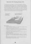
1
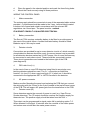
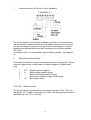
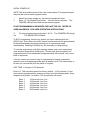
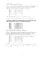
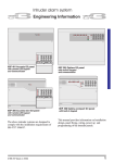
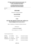
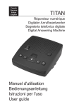
SECURIT
700L PLUS
ENGINEERING MANUAL
C & K Systems Ltd
13/03/97
NEW ENHANCED FEATURE SET
C031-096-02
Securit 700L PLUS Engineering instructions
INTRODUCTION
The Securit 700L is a microprocessor intruder alarm panel. It features seven
zones of which six are programmable plus a dedicated tamper zone. A non
volatile memory holds the programming options. These will be retained in
total power failure. Its designed to be simple to program and allow flexibility in
use.
SPECIAL FEATURES
Zone 7 programmable as Alarm, Fire or PA
Adjustable entry/exit warning sound level
Omit user disable option
Omit user part set disable option
Show panel status using remote LED
Optional remote signalling Trigger
Engineer output test facility
SYSTEM PLANNING
When the panel reaches you it will be factory programmed. This is done for
testing purposes but can also be used for installation if required. This present
program is referred to as 'factory defaults'.
It is advised that the engineer should be familiar with all the features &
options before attempting to program.
The Securit 700L should ideally be installed out of sight but remain
accessible. It should be mounted within the area covered by the alarm
system. Up to 3 remote keypads can be used on the system. The positioning
of these should be agreed with the user once the entry/exit routes and the
Night set functions have been explained.
USER/CUSTOMER CODE DEFAULTS
If at any stage you want to restore the default user/customer codes, place the
small link supplied with the spare fuse, on the memory default link (positioned
below the microprocessor in the centre of the PCB) then remove the mains
and battery supply. When the supply is restored, the panel will sound the
accept tone and the factory user/customer code defaults will be restored.
Remove the link.
NOTE... The programming defaults will not be affected, see engineer mode
9-9.
1
FACTORY DEFAULTS
User/customer Code 1
User/customer Code 2
Engineer Code
Circuit 1
Circuit 2
Circuit 3
Circuit 4
Circuit 5
Circuit 6
Circuit 7
Full Set Exit Time
Night set Exit Time
Entry time
Bell Ring Time
Chimes
1234
Disabled (0000)
7890
Entry Circuit. (Fixed)
Alarm Circuit isolated in Night set.
Alarm Circuit.
Alarm Circuit.
Alarm Circuit.
Alarm Circuit.
P.A. Circuit.
30 Seconds
15 Seconds
30 Seconds
15 Minutes
Disabled
SPECIFICATION
A
B
Power Supply
Mains Supply Voltage
PSU output voltage
Maximum output current
Aux. current
Battery Fuse
Panel Quiescent
230 V AC Nom
13.6 V Nom
1 A (total)
500 mA Max.
1 A (20 mm)
40 mA
Keypads
Supply Voltage
Quiescent Current
Active
12 V
20 mA
45 mA
Maximum Cable Run 100 M etres
C
General
Operating temperature
Humidity
Dimensions
-15°C to 50 °C
Up to 80% non condensing
263 mm (W) 223 mm (H) 82 mm
(D)
Control Panel Weight
Stand by Battery
2.7 kg Excluding Battery
2.6 Ah 12 V Rechargeable
6 Ah max.
Mounting
a
b
c
Remove the lid screws and remove lid.
Remove the PCB and keypad packaging, check the contents...
Unplug the AC mains supply.
2
d
e
Place the panel in the selected position and mark the three fixing holes.
Mount the Panel securely using all three positions.
WIRING THE CONTROL PANEL
1
Mains connection
The mains supply should be connected via one of the separated cable entries
provided. Connections should be made to the 3 way terminal block located
in bottom left of panel and wired in accordance with the relevant IEE
regulations via a fused spur. The panel must be earthed.
IF IN DOUBT CONSULT A QUALIFIED ELECTRICIAN.
2
Battery connection.
The Securit 700L requires a standby battery to be fitted to provide power in
the event of the mains failure. A sealed lead acid battery should be fitted.
Batteries up to 6 Ah may be used.
3
Detector circuits
Connections are provided for up to seven detector circuits of which normally
closed detection devices should be used. A common tamper loop is provided
for all detection devices marked as 24 HR Tamper. One or more devices may
be connected to each alarm circuit. These should be connected in series.
These circuit connections are located to the bottom right of the PCB
(see diagram B).
4
PIR Latch Line (L+)
In the event of two or more PIR detectors being fitted to any single zone,
latching detectors should be used. The 'L+' connection provides this
function. It is low (0 V) when unset and high (12 V) when set. It should be
connected to the appropriate SET or LATCH terminal in the detector.
5
AC power connector
Make sure after Mounting the panel and replacing the PCB that you connect
the white plug with the 3 wires to the 3 pins located in the top left hand corner
of the PCB. This will ensure AC power gets from the transformer to the PCB.
6
Detector reset (ID)
Some detectors require the removal of power to reset (e.g. Viper Plus or
Smoke detectors). The 'ID' output should be used as the negative supply for
these devices. The positive supply should be taken from the AUX +.
This output can be programmed to signal mains fail by selecting option 7-5.
When selected it will signal 10 minutes after the removal of the mains power
and restore one minute after the mains power returns.
3
7
Internal sounders (AC driven 16 ohm Speakers)
** DIAGRAM A **
The control panel is not fitted with a speaker in the box. It is recommended
that an extension speaker is fitted as it will greatly improve not only volume
but also the range of sounds you will get from the control panel. If internal
speakers are required they should be connected to the terminals marked
EXT. SPK .
A maximum of two 16 ohm speakers may be fitted in parallel. (see diagram
A)
8
External Sounder & Strobe.
Connection for external sounder and strobe are shown in diagram B. Please
note bell trigger shown is with output for applied negative. (Negative bell
ring).
i
ii
iii
iv
v
STS+
-R
Strobe switched negative.
Bell switched negative trigger
Bell hold off/strobe positive supply.
Bell hold off negative supply & bell tamper
Bell tamper return.
9 AUX DC - Detector power.
The auxiliary power is provided from connections marked 'AUX'. This is to
provide the 12 V supply for detectors e.g. PIR's. The auxiliary power output is
rated 500 mA max. (12 V nominal).
4
** DIAGRAM B **
MOUNTING THE REMOTE KEYPAD
a
the
b
c
Having agreed the position of any remote keypads to be fitted, mark
holes for the mounting position.
Screw the backbox in the agreed position making sure it is not twisted
Note the rear entry of cabling
WIRING THE REMOTE KEYPAD
a
main
b
wire
your
c
The remote keypads require 6 core cable for their connection to the
control panel.
Connect the cable as shown below in diagram C Making sure each
goes to a like named terminal in the panel. C goes to C, D goes to D, +
goes to + and - goes to -. The tamper wires are wired in series with
existing tamper loop.
Individual keypads do not need to be identified to the system.
** DIAGRAM C **
5
INITIAL POWER UP
NOTE The lid should be kept off the main control panel. The keypad tamper
may also be used to enter engineer mode.
i
ii
Switch the mains supply on, the internal sounder will start.
Enter 1 2 3 4 followed by # button - this will silence sounder - The
TAMPER LED will then flash on the remote keypad.
IF NO PROGRAMMING IS REQUIRED, REPLACE THE LID. REFER TO
USER HANDBOOK FOR USER OPERATING INSTRUCTIONS.
iii
out
To enter programming mode enter 7 8 9 0 - The TAMPER LED will go
The MAINS LED will flash.
To EXIT engineering, confirm any options you have selected with the *
(STAR) key. Then either close ALL tamper circuits and wait for approximately
60 seconds whereby the panel will jump out of engineering mode
automatically. Pressing # (HASH) key will manually exit engineering.
To re-enter engineering, with ALL tampers closed, enter your engineering
code and then press the # (HASH) key. This will now force the panel into
engineering and if left unattended for approximately 60 seconds it will revert
back to day mode.
If for any reason you need to stay in engineering for longer unattended
periods, once in engineering mode open a tamper circuit. The easiest way to
do this is to remove the lid of the panel or keypad.
EXIT TIME 3 0 range 10 -90 Seconds.
Enter 3-0. This has been preset for factory default - at 30 seconds. A new
time may be programmed by entering one key from the following table. Once
program is set press * to confirm. The accept tone will sound.
Enter 1
Enter 2
Enter 3
Enter 4
Enter 5
Enter 6
10 Seconds. Led 1 on.
15 Seconds. Led 2 on.
30 Seconds. Led 3 on.
45 Seconds. Led 4 on.
60 Seconds. Led 5 on.
90 Seconds. Led 6 on.
6
ENTRY TIME 3 -1 range 10-90 seconds.
Enter 3-1. Again this has been preset for factory default at 30 seconds. To
reprogram the entry time follow exactly the same directions as for the EXIT.
Again press * to confirm option. The accept tone will sound.
Enter 1
Enter 2
Enter 3
Enter 4
Enter 5
Enter 6
10 Seconds. Led 1 on.
15 Seconds. Led 2 on.
30 Seconds. Led 3 on.
45 Seconds. Led 4 on.
60 Seconds. Led 5 on.
90 Seconds. Led 6 on.
BELL DURATION (Bell ring time) 3 -2 range 3-20 minutes
Enter 3-2. This has been preset for factory default at 15 minutes. A new
time may be programmed by entering one key from the following table. Once
program is set. Press * to confirm. The accept tone will sound.
Enter 1
Enter 2
Enter 3
Enter 4
Enter 5
Enter 6
3 minutes. Led 1 on.
4 minutes. Led 2 on.
5 minutes. Led 3 on .
10 minutes. Led 4 on.
15 minutes. Led 5 on.
20 minutes. Led 6 on.
NIGHT SET EXIT TIME 3-3 RANGE 0 -90 seconds.
Enter 3-3. This has been preset for factory default 15 seconds. A new time
may be programmed by entering one key from the following table. Once
program is set. Press * to confirm. The accept tone will sound.
Enter 0
Enter 1
Enter 2
Enter 3
Enter 4
Enter 5
Enter 6
0 Seconds. All LED's off ( Instant set in Night set ).
10 Seconds. Led 1 on.
15 Seconds. Led 2 on.
30 Seconds. Led 3 on.
45 Seconds. Led 4 on.
60 Seconds. Led 5 on.
90 Seconds. Led 6 on.
NOTE: If extension speakers are fitted then the exit sounder volume can be
altered in Night set only by the control marked NIGHT SET VOLUME. The
level can be reduced to almost zero. When the control sets an accept tone
will sound.
7
CIRCUIT PROGRAMMING
Circuits 2 - 6 can be reprogrammed to suit your requirements. Circuit 1 is
fixed as a Final exit circuit. Circuit 7 can be used to set SOME options.
The method of programming is as follows:
ENTER
4-2
4-3
4-4
4-5
4-6
4-7
PROGRAM ZONE
2
3
4
5
6
7
Select the circuit you wish to alter. That circuit may then be programmed by
entering one key from the following table. Once program is set press * to
confirm. The accept tone will sound.
OPTION NUMBER
1
2
3
4
5
6
7
IF USED ON ZONE 2 - 6
Alarm
Alarm with walk through
Alarm & Isolate in Night Set
Alarm, Walk through & Isolate in N/S
Alarm, Walk through & N/S Entry
Fire
Entry Route
IF USED ON ZONE 7
Alarm
Fire
PA
SEE GLOSSARY OF TERMS FOR DESCRIPTIONS OF ZONE TYPES etc.
EXTENDED PROGRAMMING OPTIONS
These options are available to compliment your existing set-up. They control
various aspects of the usage and control of the panel.
Enter 7 - 1
Enter 7 - 2
Enter 7 - 3
Enter 7 - 4
Enter 7 - 5
Enter 7 - 6
Enter 7 - 7
Enter 7 - 8
Night set external bell disable.
Chime Enable ( See user manual for zone allocation).
Full set door sense setting.
Output mains fail to IDAllow Manual Isolation of Zone 1 (Entry/Exit) In night set.
Remote Keypad PA Enable ( Operated by * & # )
L+ signals first to alarm
Pass all low priority sounds through volume control.
Enter 8 - 1 Customer MANUAL isolate inhibit.
Enter 8 - 2 Customer Night set Inhibit.
Enter 8 - 3 Output Panel Status to IDEnter 8 - 4 L+ polarity invert.
Enter 8 - 5 Strobe test Inhibit
Press * to confirm. The accept tone will sound
8
Please note that option 7-5 ALLOWS the user to manually isolate zone 1 in
part set. It does not AUTOMATICALLY isolate zone 1 in part set.
ENGINEER ACCESS CODE
The engineer access code is programmed to 7890 as a factory default. To
change this code:
i
Enter 7 8 9 0 and remove the panel lid or keypad cover. The internal
sounder will stop when the case tamper is opened - the MAINS LED
will flash.
ii
Enter 1-1 - LEDs 1, 2, 3 and 4 will light up. Enter the new 4 digit code.
After each keypress one LED will go out. The speaker will emit an
accept
tone if the new code is acc epted. If the speaker emits an error
tone and
all LEDs are extinguished the old access code is still valid.
Repeat the procedure using a different code.
ENGINEER EVENT LOG REVIEW
The engineer log is organised into SET and UNSET events. The log will show
the first to alarm and subsequent alarms as well as isolated circuits. First to
alarm is shown by the LED being 'on' continuously. Subsequent alarms are
shown by the LED(s) flashing and isolated circuits are shown by LED(s)
pulsing slowly. The buzzer will sound whilst reviewing the 'SET' logs and will
be silent whilst reviewing the 'UNSET' logs.
To view the engineer logs proceed as follows:
From the program mode press the '5' key. The log routine will start with DAY
1 SET. The remaining logs are viewed by pressing the relevant key '2' for
2nd, '3' for 3rd etc. on to log 9. Pressing the '0' key gives the last alarm
condition.
The # key will alternate between 'SET' and 'UNSET' logs and can be used at
any time. To exit logs press the * key.
9
ENGINEER TEST OPTIONS
The engineer has available to him some test facilities so he can test bells etc.
without having to come out of engineering. These new options are accessed
by pressing 6 from the engineering mode and then selecting another option
below.
Enter 2
Enter 3
Enter 4
Enter 5
Enter 6
Enter 7
Enter 9
Internal buzzer ( entry exit sound etc. )
Internal Sounder ( Alarm sounds from speaker / keypad )
External Bell
External Strobe
L+ ( Latch Terminal for Latching Detectors )
ID- ( Impact Detector Reset )
FULL LOAD ( Everything on )
Press * to finish
FACTORY PROGRAMMING DEFAULTS 9 -9
Factory defaults have been split into two sections, programming and codes.
To return to factory programming defaults enter 9 -9 the sounder will give a
rapid pipping sound (the entry hurry up warning). Then enter the engineer
code. If entered correctly an accept tone will sound and the factory
programming defaults will be restored. If any error is made an error tone will
sound and the programming will not be altered. The user and engineer codes
are not changed.
If at any stage you want to return the panel to factory default user/customer
codes, place the small link supplied with the spare fuses, on the memory link
(positioned below the microprocessor in the centre of the PCB) then remove
the mains and battery supply. When the supply is restored, the speaker will
omit the accept tone and the factory user code defaults will be restored.
Remove the link.
10
GLOSSARY OF TERMS
FULL SET
This is a setting method normally related with leaving the premises.
NIGHT SET
This is a setting method normally used when going to bed
ALARM
This is a zone that will trigger the panel when it triggered
WALK THROUGH
This zone will trigger the panel if seen however it will ignore any activation if
an entry route has been previously triggered.
ISOLATE IN NIGHT SET
This simply means the zone will be disabled when the panel is NIGHT SET.
NIGHT SET ENTRY
This means when the panel is NIGHT SET the zone, when triggered, will start
the entry timer and the panel must be disarmed. If the panel is FULL SET
then this zone will simply act as an ALARM zone
ENTRY CIRCUIT
This will start the entry timer when set.
FIRE
This is a zone that when triggered will emit an ascending sound from the
extension speakers. If the panel is set, external sirens and strobes Will also
sound but in an unset state only internal sounders will ring.
TAMPER
This is a loop that should run through every device on your system. If broken
by a cable cut or device tampered with it will trigger the internal speakers and
if the panel is set it will trigger external sounders and strobes as well.
CHIME
Chime is similar to a doorbell. It can be used to alert a user to a certain zone
being triggered for example a front door contact can be used to know when a
door is opened or a detector can alert a user to a room being entered. CHIME
is only active when the panel is UNSET ass when it is SET the zones
functions take over.
DOOR SENSE SETTING
This allows you to have variable FULL SET EXIT TIME. You can set your
EXIT time to 90 seconds and when you are setting your system to leave the
premises
the exit time will drop to 8 seconds as soon as the EXIT door has closed. This
means in affect you have an 8-90 second exit time.
THE * KEY (STAR)
This is commonly used as an ACCEPT or CHANGE button
THE # KEY (HASH)
This is commonly used as RESET, CANCEL or EXIT
11
SERIES AND PARALLEL
Here is a simple example of SERIES and PARALLEL wiring. Notice how the
Power and C & D lines are in parallel and the Tamper lines are in series.
Manual Version 1.2 13/03/97
C&K Systems Ltd.
Unit 24 Walkers Road
North Moons Moat Industrial Estate
Redditch
Worcs.
B98 9HE
Tel : +44 (0)1527 68111
Fax : +44(0)1527 68222
Technical Support : 0345 660533 9am - 5pm weekdays
Local rate call only - UK Only
ZONE
1
2
3
4
ZONE USE / LOCATION
KEYS
ENTERED
RESISTANCE
Ω
Ω
Ω
Ω
12
5
6
7
TIMER
FULL
NIGHT
EXT SOUNDER
TICK BOX
EXTENDED OPTIONS
BATTERY VOLTAGE
AUX. VOLTAGE
INSTALLED BY
Ω
Ω
Ω
KEYS ENTERED
VALUE
1
2
3
4
5
SECONDS
SECONDS
MINUTES
6
7
CHECKED
V
V
THIS INFORMATION SHOULD BE KEPT EITHER INSIDE THE CONTROL PANEL OR
WITH THE INSTALLER. IT CAN BE USED TO REFER TO PROGRAMMING DETAILS
WHEN NEEDED.
700L CONTROL PANEL
SONADE 2000
STSTROBE-
NO
B
BELL+
D
0V
A
-R
T
FLASHGUARD XL+
STROBE-
SIREN-
SUPPLY+
SUPPLY-
TAMPER OUT
STARLIGHT 2000
ST
-R
+H
-H
RTN
ACTIVEGUARD
STB-
-S
+12V
-12V
ACTIVE GUARD 3
ST-
-SW
V+
V-
RIGHT HAND
TAMPER
RET
SECURIGUARD
STROBE-
S-
SUPPLY+
SUPPLY-
NOVA GUARD 2+T
STROBE-
S-
12V+
12V-
LEFT HAND
TAMPER
R
SPIRIT AU1000
STB-
TRG-
HOLD OFF +
HOLD OFF -
RTN-
GENERAL TERMINALS
STROBE
TRIG -
SIREN
TRIG -
SUPPLY+
SUPPLY-
TAMPER
RETURN
13