1
MICROWAVE OVEN
CE979GSE
SERVICE
MICROWAVE OVEN
Manual
CONTENTS
1. Precautions
2. Specifications
3. Operating Instructions
4. Disassembly and Reassembly
5. Alignment and Adjustments
6. Circuit Description
7. Troubleshooting
8. Exploded Views and Parts List
9. PCB Diagrams
10. Schematic Diagrams
TAWIL
1. Precaution
Follow these special safety precautions. Although the microwave oven is completely safe during ordinary
use, repair work can be extremely hazardous due to possible exposure to microwave radiation, as well as
potentially lethal high voltages and currents.
1-1 Safety precautions (
)
1. All repairs should be done in accordance
with the procedures described in this
manual. This product complies with
Federal Performance Standard 21 CFR
Subchapter J (DHHS).
2. Microwave emission check should be
performed to prior to servicing if the oven is
operative.
3. If the oven operates with the door open :
Instruct the user not to operate the oven and
contact the manufacturer and the center for
devices and radiological health immediatly.
4. Notify the Central Service Center if the
microwave leakage exceeds 5 mW/cm2
5. Check all grounds.
6. Do not power the MWO from a "2-prong"
AC cord. Be sure that all of the built-in
protective devices are replaced. Restore any
missing protective shields.
7. When reinstalling the chassis and its
assemblies, be sure to restore all protective
devices, including: nonmetallic control
knobs and compartment covers.
8. Make sure that there are no cabinet openings
through which people--particularly
children--might insert objects and contact
dangerous voltages. Examples: Lamp hole,
ventilation slots.
9. Inform the manufacturer of any oven found
to have emmission in excess of 5 mW/cm2,
Make repairs to bring the unit into
compliance at no cost to owner and try to
determine cause.
Instruct owner not to use oven until it has
been brought into compliance.
11. To avoid any possible radiation hazard,
replace parts in accordance with the wiring
diagram. Also, use only the exact
replacements for the following parts:
Primary and secondary interlock switches,
interlock monitor switch.
12. If the fuse is blown by the Interlock Monitor
Switch: Replace all of the following at the
same time: Primary and secondary switches,
as well as the Interlock Monitor Switch. The
correct adjustment of these switches is
described elsewhere in this manual. Make
sure that the fuse has the correct rating for
the particular model being repaired.
13. Design Alteration Warning:
Use exact replacement parts only, i.e.,
only those that are specified in the
drawings and parts lists of this manual.
This is especially important for the
Interlock switches, described above.
Never alter or add to the mechanical or
electrical design of the MWO. Any design
changes or additions will void the
manufacturer's warranty.10.Always unplug
the unit's AC power cord from the AC
power source before attempting to
remove or reinstall any component or
assembly.
14. Never defeat any of the B+ voltage
interlocks. Do not apply AC power to the
unit (or any of its assemblies) unless all
solid-state heat sinks are correctly installed.
15. Some semiconductor ("solid state") devices
are easily damaged by static electricity. Such
components are called Electrostatically
Sensitive Devices (ESDs). Examples include
integrated circuits and field-effect
transistors.
Immediately before handling any
semiconductor components or assemblies,
drain the electrostatic charge from your
body by touching a known earth ground.
CENTRAL SERVICE CENTER
10. Service technicians should remove their
watches while repairing an MWO.
Samsung Electronics
16. Always connect a test instrument's ground
lead to the instrument chassis ground before
connecting the positive lead; always remove
the instrument's ground lead last.
1-1
Pretaution
1-2 Special Servicing Precautions (Continued)
17. When checking the continuity of the witches
or transformer, always make sure that the
power is OFF, and one of the lead wires is
disconnected.
18. Components that are critical for safety are
indicated in the circuit diagram by
shading,
or
.
19. Use replacement components that have the
same ratings, especially for flame resistance
and dielectric strength specifications. A
replacement part that does not have the
same safety characteristics as the original
might create shock, fire or other hazards.
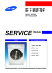
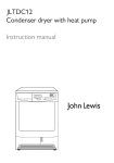
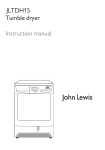
1-3 Special High Voltage Precautions
1. High Voltage Warning
Do not attempt to measureany of the high
voltages--this includes the filament voltage
of the magnetron. High voltage is present
during any cook cycle.
Before touching any components or wiring,
always unplug the oven and discharge the
high voltage capacitor (See Figure 1-1)
2. The high-voltage capacitor remains charged
for about 30 seconds after disconnection.
Short the negative terminal of the highvoltage capacitor to to the oven chassis.
(Use a screwdriver.)
3. High voltage is maintained within specified
limits by close-tolerance, safety-related
components and adjustments. If the high
voltage exceeds the specified limits, check
each of the special components.
Fig. 1-1. Discharging the High Voltage Capacitor
1-2
Samsung Electronics
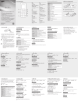
2. Specifications
2-1 Table of Specifications
TIMER
99Mins
POWER SOURCE
230V 50Hz, AC
POWER LEVEL
%
POWER CONSUMPTION
OUTPUT POWER
MICROWAVE : 1,500W
ON TIME
OFF TIME
CE979GSE
10%
85W
4 sec
26 sec
MAX : 1,500W
20%
170W
7 sec
23 sec
GRILL : 1,300W
30%
255W
10 sec
20 sec
FROM 85W TO 850W (10 LEVEL POWER)
40%
340W
13 sec
17 sec
50%
425W
16 sec
14 sec
(IEC-705 TEST PROCEDURE)
60%
510W
19 sec
11 sec
OPERATING FREQUENCY
2,450MHz
70%
595W
22 sec
8 sec
MAGNETRON
OM75PH(31)ESS
80%
680W
25 sec
5 sec
COOLING METHOD
COOLING FAN MOTOR
90%
765W
28 sec
2 sec
OUTSIDE DIMENSIONS
517(W) x 340H) x 435(D)
100%
850W
30 sec
0 sec
2-2 Comparison Chart
MODEL
FEATURE
Samsung Electronics
CE979GSE
MORE/LESS
O
AUTO COOK/DISH
O
AUTO DEFROST
O
AUTO REHEAT
O
TIME COOK
O
POWER LEVEL
O
GRILL
O
MICROWAVE/GRILL
O
2-1
3. Operating Instructions
3-1 Control Panel
Cehcop
Cehcop
GRILL / COMBI
STOP / CANCEL
START
1 Min
deodorization
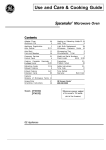
3-2 Features & External Views
DOOR LATCHES
,,,,,,,,,,,,,,,,,,,,,,,,,,,,,,,,,,,,,,,,
,,,,,,,,,,,,,,,,,,,,,,,,,,,,,,,,,,,,,,,,
,,,,,,,,,,,,,,,,,,,,,,,,,,,,,,,,,,,,,,,,
,,,,,,,,,,,,,,,,,,,,,,,,,,,,,,,,,,,,,,,,
,,,,,,,,,,,,,,,,,,,,,,,,,,,,,,,,,,,,,,,,
,,,,,,,,,,,,,,,,,,,,,,,,,,,,,,,,,,,,,,,,
,,,,,,,,,,,,,,,,,,,,,,,,,,,,,,,,,,,,,,,,
,,,,,,,,,,,,,,,,,,,,,,,,,,,,,,,,,,,,,,,,
,,,,,,,,,,,,,,,,,,,,,,,,,,,,,,,,,,,,,,,,
,,,,,,,,,,,,,,,,,,,,,,,,,,,,,,,,,,,,,,,,
,,,,,,,,,,,,,,,,,,,,,,,,,,,,,,,,,,,,,,,,
,,,,,,,,,,,,,,,,,,,,,,,,,,,,,,,,,,,,,,,,
,,,,,,,,,,,,,,,,,,,,,,,,,,,,,,,,,,,,,,,,
,,,,,,,,,,,,,,,,,,,,,,,,,,,,,,,,,,,,,,,,
,,,,,,,,,,,,,,,,,,,,,,,,,,,,,,,,,,,,,,,,
,,,,,,,,,,,,,,,,,,,,,,,,,,,,,,,,,,,,,,,,
,,,,,,,,,,,,,,,,,,,,,,,,,,,,,,,,,,,,,,,,
,,,,,,,,,,,,,,,,,,,,,,,,,,,,,,,,,,,,,,,,
,,,,,,,,,,,,,,,,,,,,,,,,,,,,,,,,,,,,,,,,
,,,,,,,,,,,,,,,,,,,,,,,,,,,,,,,,,,,,,,,,
,,,,,,,,,,,,,,,,,,,,,,,,,,,,,,,,,,,,,,,,
,,,,,,,,,,,,,,,,,,,,,,,,,,,,,,,,,,,,,,,,
,,,,,,,,,,,,,,,,,,,,,,,,,,,,,,,,,,,,,,,,
,,,,,,,,,,,,,,,,,,,,,,,,,,,,,,,,,,,,,,,,
,,,,,,,,,,,,,,,,,,,,,,,,,,,,,,,,,,,,,,,,
,,,,,,,,,,,,,,,,,,,,,,,,,,,,,,,,,,,,,,,,
,,,,,,,,,,,,,,,,,,,,,,,,,,,,,,,,,,,,,,,,
,,,,,,,,,,,,,,,,,,,,,,,,,,,,,,,,,,,,,,,,
,,,,,,,,,,,,,,,,,,,,,,,,,,,,,,,,,,,,,,,,
,,,,,,,,,,,,,,,,,,,,,,,,,,,,,,,,,,,,,,,,
,,,,,,,,,,,,,,,,,,,,,,,,,,,,,,,,,,,,,,,,
,,,,,,,,,,,,,,,,,,,,,,,,,,,,,,,,,,,,,,,,
,,,,,,,,,,,,,,,,,,,,,,,,,,,,,,,,,,,,,,,,
,,,,,,,,,,,,,,,,,,,,,,,,,,,,,,,,,,,,,,,,
,,,,,,,,,,,,,,,,,,,,,,,,,,,,,,,,,,,,,,,,
,,,,,,,,,,,,,,,,,,,,,,,,,,,,,,,,,,,,,,,,
,,,,,,,,,,,,,,,,,,,,,,,,,,,,,,,,,,,,,,,,
DOOR
Samsung Electronics
LIGHT
GLASS TRAY
,,,,,,,,,,,,,,,,,,,,,,,,,,,,,,
,,,,,,,,,,,,,,,,,,,,,,,,,,,,,,
,,,,,,,,,,,,,,,,,,,,,,,,,,,,,,
,,,,,,,,,,,,,,,,,,,,,,,,,,,,,,,,,,,,,,,,,,,,,
,,,,,,,,,,,,,,,,,,,,,,,,,,,,,,
,,,,,,,,,,,,,,,,,,,,,,,,,,,,,,
,,,,,,,,,,,,,,,,,,,,,,,,,,,,,,,,,,,,,,,,,,,,,
,,,,,,,,,,,,,,,,,,,,,,,,,,,,,,
,,,,,,,,,,,,,,,,,,,,,,,,,,,,,,,,,,,,,,,,,,,,,
HEATER
DISPLAY
,,,,,,,,,,,,,,,
,,,,,,,,,,,,,,,
,,,,,,,,,,,,,,,
,,,,,,,,,,,,,,,
,,,,,,,,,,,,,,,
,,,,,,,,,,,,,,,
,,,,,,,,,,,,,,,
,,,,,,,,,,,,,,,
,,,,,,,,,,,,,,,
,,,,,,,,,,,,,,,
,,,,,,,,,,,,,,,
,,,,,,,,,,,,,,,
,,,,,,,,,,,,,,,
,,,,,,,,,,,,,,,
,,,,,,,,,,,,,,,
,,,,,,,,,,,,,,,
,,,,,,,,,,,,,,,
,,,,,,,,,,,,,,,
,,,,,,,,,,,,,,,
,,,,,,,,,,,,,,,
,,,,,,,,,,,,,,,
,,,,,,,,,,,,,,,
VENTILATION GUIDE INHALATION SAFETY
CONTROL
INTERLOCK
HOLES
PANEL
SLOT
ROLLER
HOLES
3-1
4. Disassembly and Reassembly
4-1 Removal of Outer Panel
1. Remove five screws from the rear section.
2. Lift the outer panel by pulling it backwaeds
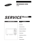
4-2 Replacement of Magnetron and Fan Motor
1.
The magnetron incudes the shield case,
permanent magnet, check coils and 500pF
capacitors (all contained in one assembly).
2. Discharge the high voltage capacitor.
(See page1-2)
3. Disconnect all lead wires from the magnetron.
4. Remove screw(1) securing the magnetron
supporter.
5. Remove the magnetron supporter.
6. Remove the air cover
7. Remove screws(2) securing the thermal cutout
switch.
8. Remove screws securing the magnetron to the
wave guide.
9. Remove the magnetron very carefully.
10. Remove screws from the back panel to take
out fan motor.
11. When removing the magnetron, make sure
that its antenna does not hit any adjacent
parts.
12. When replacing the magnetron, be sure to
remount the magnetron gasket in the correct
position, and make sure the gasket is in good
condition.
Samsung Electronics
Cover Air
Screw(2)
Screw(1)
Magnetron Fan Motor
4-1
Disassembly and Reassembly
4-3 Replacement of High Voltage Transformer
1. Discharge the high voltage capacitor.
(See page 1-2)
2. Disconnect all the leads.
3. Remove four screws.
4. When replacing, connect the leads securely.
H.V.CAPACITOR
H.V.TRANS
H.V.FUSE
4-4 Replacement of Door Assembly
1.
2.
3.
Remove bolts securing the upper hinge and
lower hinge, then remove the door assmbly.
After replacing the door, check the operation
of the primary interlock switch, the secondary
interlock switch and the interlock monitor
switch.
Microwave emission should not exceed
5§ /§† (All service adjustments should be
made for minimum RF emission.)
HINGE VOLT
HINGE UPPER
HINGE VOLT
4-2
Samsung Electronics
Disassembly and Reassembly
4-5 Replacement of Lamp
1. Disconnect harness-"A" assembly.
2. Remove screw securing the lamp cover
Lamp cover
Screw
4-6 Replacement of Elevation Motor
1.
Remove the glass tray and assembly from
cavity.
2. Turn the oven upside down.
3. Remove screws securing the elevation motor
cover.
4. Disconnect all lead wires from the elevation
motor.
5. Remove screws securing the elevation motor
to the cavity.
6. Remove the elevation motor.
7. When replacing the elevation motor, be sure
to remount it in the correct position.
8. Reconnect all the leads to the elevation motor.
9. Screw the elevation motor cover to the base
plate with screw driver.
10. Remount the coupler in the correct position.
SCREW
SCREW
ELEVATION MOTOR COVER
SCREW
ELEVATION
MOTOR
TANTABLE
MOTOR
WEIGHT SENSOR
SCREW
Samsung Electronics
4-3
Disassembly and Reassembly
4-7 Replacement of Grill Heater
1. Remove the outer panel.
2. Disconnect all the connectors and terminals on
the heater and noise filter assembly.
3. Unscrew nuts securing the grill heater.
PLATE SRRING
GRILL
HEATER
SCREW
BRACKET HEATER
4-8 Replacement of Interlock Monitor Switch and Door Sensing Switch
1. Disconnect all lead wires from the interlock
monitor switch and the door sensing switch.
2. Push up the mounting tabs.
3. Make necessary adjustments Do the microwave
emission check according to "ALIGNMENT
AND ADJUSTMENTS" on page 5-2(whenever
they any repaired or replaced).
Primary Interlock S/W
4-9 Replacement of Primay Interlock Switch
1. Disconnect all lead wires from the primary
interlock switch.
2. Push up the mounting tabs which support the
primary interlock switch.
Lever Switch
Interlock Monitor S/W
3. Make necessary adjustments and microwave
emision check according to "ALIGNMENT
AND ADJUSTMENTS" on page 5-2(whenever
they are repaired or replaced).
Guide S/W
Interlock Switch Replacement
When replacing defective switches, be sure to
check that the mointing tabs are not bent or
broken.
Door Sensing S/W
4-4
Body Latch
Samsung Electronics
Disassembly and Reassembly
4-10 Replacement of Fuse
1. Disconnect the oven from the power source.
2. Remove the 10A fuse from the fuse holder.
3. When replacing the 10A fuse, use an exact
replacement and check the primary interlock ,
door sensing and interlock monitor switches.
4. When the above switches operate properly,
check that the control circuit transformer is not
defective.
4-11 Replacement of Control Circuit Board
1. Be sure to disclyarge any static electricity from
your body, and avoid touching the "Touch
control" clrcuitry.
2. Disconnect the connectors from the control
circuit board.
3. Remove screws ¥L and ¥Msecuring the control
circuit bord.
4. Lift up the control circuit board from right side
and remove the hooks holding the contol
circuit board to the box assembly.
Screw¥L
Screw¥M
4-12 Replacement of Gas Sensor and ThermoSwitch
1. Disconnect all lead wires from the gas sensor
and the thermostat.
2. Remove screws securing the air guide.
thermostat
Gas sensor
Samsung Electronics
4-5
5. Alignment and Adjustments
PRECAUTION
1. High voltage is present at the high voltage terminals during any cook cycle.
2. Do not attempt to measurement the high voltage.
3. Before touching any oven components or wiring, always unplug the oven and discharge the high voltage capacitor.
5-1 High Voltage Transformer
1. Remove connectors from the transformer terminals
and check continuity.
2. Normal resistance readings are as follows:
MODEL
Secondary
Filament
Primary
Filament Terminals
CE979GSE
Approx. 96Ω
Approx.0Ω
Approx.1.6Ω
(Room temperature = 20ûC)
Secondary
Terminal
Primary
Terminals
5-2 Low Voltage Transformer
1. The low voltage transformer is located on the
control circuit board.
2. Remove the low voltage transformer from the
PCB Ass'y and check continuity.
3. Normal resistor readings a shown in the table.
Terminals
1~3(Input)
4~5(Output 15.5V)
5~6(Output 7.3V)
7~8(Output 3.2V)
8~9(Output 2.7V)
Resistance
75.9Ω
1.1Ω
0.5Ω
0.7Ω
0.5Ω
5-3 Magnetron
1. Continuity checks indicate only an open filament
or a shorted magnetron. To diagnose an open
filament or shorted magnetron, do the following:
2. Isolate the magnetron from the circuit by
disconnecting its leads.
3. A continuity check across the magnetron filament
terminals should indicate one ohm or less.
4. A continuity check between each filament terminal
and the magnetron case should read open.
Magnetron Antenna
Gasket Plate
Cooling Fins
Samsung Electronics
5-1
Alignment and Adjustments
5-4 High Voltage Capacitor
1. Check continuity of the capacitor with the meter set at the highest resistance scale.
2. Once the capacitor is charged, a normal capacitor shows continuity for a short time, and then indicates 9MΩ.
3. Shorted capacitor indication: continuity.
4. Open capacitor noication constant 9MΩ.
5. Resistance between each terminal and chassis should read infinite.
5-5 High Voltage Diode
1. Isolate the diode from the circuit by disconnecting its leads.
2. With the ohm-meter set at the highest resistance scale, measure across the diode terminals. Reverse the
meter leads and read the resistance.
A meter with 6V, 9V or higher voltage batteries should be used to check the front-to back resistance of the
diode. (Otherwise an infinite resistance may be read in both directions.) The resistance of a normal diode
will be infinite in one direction and several hundred KΩ in the reverse direction.
5-6 Main Relay and Power Control Relay
1. The relays are located on the PCB Ass'y. Isolate them from the main circuit by disconnecting the leads.
2. Operate the microwave oven with a water load. Set the power level to "high"
3. Check continuity between terminals of the relays after the start pad is pressed.
5-7 Adjustment of Primary Switch, Door Sensing Switch and Monitor Switch
Precaution
For continued protection against radiation hazard, replace parts in accordance with the wiring diagram and be sure to use the
correct part number for the following switches: Primary and secondary interlock switches, and the interlock monitor switch
(replace all together). Then follow the adjustment procedures below. After repair and adjustment, be sure to check the continuity
of all interlock switches and the interlock monitor switch.
1. When mounting primary switch and interlock
monitor switch to latch body, consult the figure.
2. No specific adjustment is necessary during
installation of primary switch and monitor
switch to the latch body is necessary.
3. When mounting the Latch Body to the oven
assembly, adjust the Latch Body by moving it so
that the oven door has vo "play". Check for play
by pulling the door assembly. Make sure that
the latch keys move smoothly after adjustment
is completed. Completely tighten the screws
holding the latch body to the oven assembly.
Primary Interlock Switch
Interlock Monitor
Switch
Body Latch
Guide switch
Lever Door(B)
4. Reconnect to Monitor switch and re-check that
the the monitor circuit and all latch switches are
secured.(see components test procedures).
5. Confirm that the gap between the switch
housing and the switch actuator is no more than
0.5mm when door is closed.
5-2
Door Sensing
Switch
Primary switch
Monitor switch (COM-NC)
Monitor switch (COM-NO)
Door Sensing S/W
Door Open
∞
0
∞
∞
Door Closed
0
∞
0
0
Samsung Electronics
Alignment and Adjustments
5-8 Output Power of Magnetron
CAUTION
MICROWAVE RADIATION
DO NOT ALLOW EXPOSURE TO MICROWAVE RADIATION FROM ANY PARTS CONDUCTING MICROWAVE ENERGY.
The output power of the magnetron can be measured by performing a water temperature rise test.
Equipment needed :
* One 1-liter cylindrical borosilicate glass vessel (Outside diameter 190 mm)
* One glass thermometer with mercury column
NOTE: Check line voltage under load. Low voltage will lower the magnetron output. Brenk the line here
make all temperature and time tests with accurate equipment.
1. Fill the one liter glass vessel with water.
2. Stir water in glass vessel with thermometer, and record glass vessel's temperature ("T1", 10±1ûC).
3. After moving the water into another glass vessel, place it in the center of the cooking tray. Set the oven to high
power and operate for 51 seconds exactly. (3 seconds included as a holding time of magnetron oscillation.)
4. When heating is finished, stir the water again with the thermometer and measure the temperature ("T2").
5. Subtract T1 from T2. This will give you the water temperature rise. (∆T)
6. The output power is obtained as follows :
Output Power =
4.187 x 1000 x ∆T
49
49 : Heating Time (sec)
4.187 : Coefficient for Water
1000 : Water (cc)
∆T : Temperature Rise (T2-T1)
* Output (W) = 85.5x ∆T
7. Normal temperature rise for this model is 9ûC to 11ûC at 'HIGH'.
NOTE 1: Variations or errors in the test procedure will cause a variance in the temperature rise.
Additional power test should be done if temperature rise is marginal.
NOTE 2: Output power in watts is computed by multiplying the temperature rise (step E) by a factor of 91
times the centigrade temperature.
5-9 Uniformity of Microwave Heat Distribution
The microwave heat distribution can be checked indirectly by measuring the water temperature rise at
certain positions in the oven:
1. Prepare five beakers made of 'Pyrex', each having 100 milliliters capacity.
2. Measure exactly 100milliliters off water load with a measuring cylinder, and pour into each beaker.
3. Measure the temperature of each water load. (Readings shall be taken to the first decimal.)
4. Put each beaker in place on the cooking tray as illustrated in the figure. Start heating.
5. After heating for 2 minutes, measure the water temperature in each beaker.
6. Microwave heat distribution rate can be calculated as follows:
Heat Distribution =
Minimum
Temperature Rise
Maximum
Temperature Rise
D
X 100(%)
Beaker
D
D/4
The result should exceed 65%.
D/4
D/4
D/4
Samsung Electronics
Cooking Tray
5-3
Alignment and Adjustments
5-9 Leakage Measuring Procedure
5-9-1 Equipment
1. Microwave Energy Survey Meter
2. Glass beaker, 600cc
3 Mercurial or digital thermometer 100ûC or 212ûF
5-9-2 Procedure for Measurement of Microwave Leakage
1. Pour 275±15cc of 20±5ûC (68±9ûF) in toA 600cc graduated beaker. Place the beaker in the center of the
oven.
2. Start the oven and measure the leakage using a microwave energy survey meter.
3. Set survey meter ( dual ranges) to 2,450MHz.
4. When measuring the leakage, always use the 2 inch spacer cone with the probe. Hold the probe
perpendicular to the cabinet door. Place the spacer cone on the door seam and move the probe along
the viewing windows and exhaust openings. Move the probe at about 1 inch per second.
If the leakage from door seam is measured near a corner, keep the probe perpendicular, making sure
the probe end(at the base of the cone) does not gt closer than 2 inches to any metal (otherwise,
erroneous readings readings will result).
5. The measured leakage must be less than 5mW/cm2.
WARNING
AVOID TOUC HING THE HIGH VOLTAGE COMPONENTS.
Samsung Electronics
5-4
Alignment and Adjustments
5-9 Leakage Measuring Procedure
5-9-3 Check for Microwave Leakage
( With the opter panel removed)
1. Remove the outer panel.
2. Pour 275±15cc of 20±5ûC(68±9ûF) water in a beaker which is graduated to 600cc, and place the beaker
in the center of the oven.
3. Start the oven at the highest power level.
4. Set survey meter dual ranges to 2,450MHz.
5. Using the survey meter and spacer cone as described above, measure arnear the opening of
magnetron, the surface of the air guide and the surface of the wave guide as shown in the following
photo.( but avoid the high voltage components.) The neading should be less than 5mW/cm2.
5-9-4 Measurement Notes
1. Do not exceed the limited scale.
2. The test probe must be held on the grip of the handle, otherwise a false reading may result when the
operator's hand is between the handle and the probe.
3. When high leakage is suspected, do not move the probe horizontally along the oven surface; this may
cause damage to the probe.
4. Follow the recommendation of the manufacturer of the microwave energy survey meter.
5-9-5 Record Keeping and Special Notification
1. After adjustment and repair of a radiation protection device, record for the measured values, and keep
the data.
2. If the radiation leakage exceeds 5mW/cm2 (after determining that all parts are in good condition,
functioning properly and that central service center identical parts are replaced as listed in this
manual) notify the central repair facility.
3. At least once a year have the Microwave Energy Survey Meter checked for accuracy by its
manufacturer.
Samsung Electronics
5-5
6. Circuit Description
6-1 When food is placed inside oven and door is closed
1. Low voltage transformer supplies the necessary voltage to the touch control circuit when power cord is
plugged in.
2. The primary interlock switch is closed.
3. The interlock monitor switch is opened. This interlock monitor switch blows the 10A fuse and stops
magnetron oscillation when the door is opened (abnormal condition).
4. The door key is caught by the door hook, this clodesthe door sensing switch is closed to send the doorclose signal to the touch control circuit.
6-2 When cooking, power and time are set by touching the function pads
1. The time appears in the display window.
2. The touch control circuit stores the cooking data at.
6-3 When the START pad is touched
1. The main relay and the power control relay are controlled by the touch control circuit.
2. An oven lamp lights the inside of the oven by (The lamp relay in the Touch Control Circuit).
3. The fan motor rotates and cools the magnetron by blowing the air from the intake (on the back panel)
over the magnetron fins. After cooling the fins, this air is directed into the oven to blow out the vapor.
Magnetron
Primary Switch
Lamp
L
DC12V
Lamp Relay
H.V.Trans
Interlock
Monitor
Switch
H.V.
Capacitor
Diode
Monitor Fuse
Main Relay
Power Relay
H.V.
TRANS
4. 230V~50Hz AC is applied to the high voltage transformer through the contacts of primary windings (
shown by the solid line) just after the power control relay turns ON. (Fig. 1)
5. 3.4V AC is generated from the filament winding of the high voltage transformer. This 3.4V is applied to
the magnetron to heat the magnetron filament through two noise preventing choke coils.
6. High voltage (2,230 volts AC) is generated by the high voltage transformer secondary. This secondary
voltage is increased by the diode and high voltage capacitor. This resultant DC voltage is then applied
to the anode of the magnetron. As shown in Fig. 2, the first half cycle of the high voltage produced in
the secondary high voltage transformer charges the high voltage capacitor.The dotted lines indicate the
current flow. During operation of the second half cycle, the voltage produced by the transformer
secondary (plus the charge of the high voltage capacitor) is applied to the magnetron as shown in the
solid line, which cawses the magnetron to oscillate. The electrlcal interference generated by the
magnetron is prevented by the 1.6uH choke coils, 500pF filter capacitors and the magnetrons shielded
case (so that TV and radio signals are immune).
7. The power control relay is turned on intermittently by the touch control circuit (when the oven is set at
any power) except full power. The touch control circuit controls the ON/OFF time of the power control
relay in order to vary the output power of the microwave oven from Low to "Full" power. One
complete ON/OFF cycle of the power control is 30 seconds.
8. The cooking when the oven is set at any power setting is shown on the display (starts to count down.)
Samsung Electronics
6-1
Circuit Description
6-4 When the door is opened during cooking
1. The primary interlock switch is opened to cut off the primary voltage of the high voltage transformer.
Thes stops microwave oscillation.
2. The door sensing switch is opened which signals the touch control circuit. The main relay stays on, the
power control relay turns off and the display stops counting down.
3. The fan motor and turn-table motor are stopped by operation of the primary interlock switch. The oven
lamp lights the inside of the oven again until the door is closed.
4. Upon opening the door, the contacts of the primary interlock switch open and the contacts of interlock
monitor switch close.
5. If the contacts of primary interlock switch do not function properly, the monitor fuse blows out because
of the large current surge (caused by the monitor switch activation, which stops magnetron oscillation).
see Fig. 3
Primary Switch
Monitor Fuse
Sec Switch
H.V.Trans
Interlock
Monitor
Switch
Power Relay
6-5 When the CANCEL pad is touched during cooking
1. Touching the CANCEL pad once stops cooking. Touching on the pad twice cancels all programs stored
in the touch control circuit. The time of day reappears on the display window.
2. The oven lamp and cooking indicators turn off.
3. The fan motor stops.
4. The power control relay turns off to cutting the primary voltage to the high voltage transformer (This
stops magnetron oscillation).
6-2
Samsung Electronics
7. Troubleshooting
7-1 Checking the Weight Sensor
7-1-1. Overview
Elevarion motor
Shaft
Tantable motor
Weight sensor
7-1-2. Operation
1. If the weight of the food is less than 1.5Kg (including the cooker), the rotating dish automatically
moves to the optimum location by the elevation motor.
(If the weight is more than 1.5Kg the cooking is done in the basic location)
2. When defrosting, the weight sensor detects the weight and moves the food to the appropriate
height . (The elevation operates when the weight is less thon1.0Kg or less (including the dish)).
3. When reheating food 700g or less (including the dish), it swings once and then cookis in the basic
location. (If the weight is 700g the cooking is done in the basic location)
4. Manual cooking is done in the basic location with only the rotating motor operating.
(Maximum of 4Kg including the dish if the weight exceeds 4kg, an ÒE5Ó error occurs.)
7-1-3. Operating Principle of the Height Sensor
( Output Wave )
5V
0V
The output frequency of the basic condition (when 0
point adjusted) is between 3150 and 3650Hz.
The weight sensor converts the weight of the food into a series of pulses that are compared to
the"zero point" wavefrom. This frequency difference determines the cooking time.
Samsung Electronics
7-1
Troubleshooting
7-1-4. Zero point and Inclination Adjustment
1. Turn the power on again and set time initial condition to Ò8888Ó.
2. Put a dish inside the cooking space.
3. Press the sensor defrost(
) and power level/more,less(
) keys simultaneously until Ò0000Óis
displayed (about 5 seconds).At this time lamp and the rotating dish motor are on.
4. After 10 seconds, A normal neading is between 3150 and 3650.
5. Put the 1Kg standard weight at the center of the glass tray and close the door.
(When setting the 1Kg weight, put the metal rack, roasting spit, glass bowl and two skewers on the
glass tray. Then do the zero point adjustement.)
(Metal Rack) (roasting spitspit)
(two skewers)
(glass bowl)
6. Press the sensor reheat(
) and power level/more,less(
) keys simultaneovsly until the Ò1111Óis
displayed. (about 5 seconds). At this time lamp and the rotating dish motor are on.
7. After 10 seconds, A normal reading is between 0350 and 0650.
8. Press the cancel key to complete the adjustment.
7-1-5. Error codes
Error indication
7-2
Cause of occurrence
Management method
Remarks
E0
Gas sensor open/short
(sensor value
between 6 and 211)
Check the connection and
cooking reheating
Put the power switch again and
and use it after 10 minutes.
Automatic
reheating
E1
Exceeds of T1 time limit
(gas sensor)
First press the cancel key and
check if the food is positiotes
Automatic
reheating
E4
Problem with the weight
sensor (Output frequency=0Hz)
Exchange the weight sensor
Check the wire connection
E5
Excess of maximum weight
(The total weight exceeded
4Kg)
Cook within 4Kg
E6
Excess of maximum allowed
time with maximum load
(When cooking food that
weight less tman 300g the
maximum time is 10 minutes.)
When cooking 300g or less,
cook within 10minutes.
E8
No tray (Occurs if oven is
operated without the rotating
dish.)
Install the rotating dish
E10
Problen with the EEPROM
Replace the PCB assy
Samsung Electronics
Troubleshooting
7-1-6. Hidden key
1. Check the gas sensor : Press the sensor defrost and sensor reheat keys simultaneovsly.
(Display : Between 5 and 210).
2. Child lock function : Press the cancel key for 3 seconds
(the function is executed after the buzzer sounds). To ondo the child lock,
press the cancel key for 3 seconds.
3. Cooking completion remind function : If the food is not removed after cooking,
the buzzer sounds every minute.
7-1-7. Precautions
1. Do not apply heavy load or pressure on the rotating dish
(The elevation and the weight sensor directly contact the rotating dish).
Putting food that exceeds 4kg(Total) can damage the weight sensor.
2. Use only genuine replacements that fit the model(C.E., rotating dish and supporter).
3. When food exceeding 300g(Total) is put on the rotating dish, the oven operates for only 10 minutes.
(Error E6 occwrs.)
7-1-8. Reppacing Parts
1. Discharge the capacitor for about 5 to 6 minutes after cutting the power, and then continue the work.
2. Do not damage the coating on the wires.
3. When removing the wire the terminal, hold the positive lock case with the finger and assemble it.
Otherwise use a tool (such as long nose pliers)
4. If you remove the tie during servicing, do not damage the wire. Adjust and arrange the wire and
tie(heat proof onsulated tie) after the repairs have been completed.
Samsung Electronics
7-3
Troubleshooting
PRECAUTION
1. FIRST CHECK THE GROUND CONNECTIONS.
2. BE CAREFUL OF THE HIGH VOLTAGE CIRCUIT.
3. DISCHARGE THE HIGH VOLTAGE CAPACITOR.
4. WHEN CHECKING THE CONTINUITY OF THE SWITCHES OR TRANSFORMER, DISCONNECT ONE LEAD WIRE FROM THESE
PARTS AND THEN CHECK CONTINUITY WITHOUT THE POWER SOURCE ON. OTHERWISE YOU MIGHT DAMAGE THE METER
ORGET APTISE READING.
5. DO NOT TOUCH ANY PART OF THE CIRCUIT OR THE CONTROL CIRCUIT BOARD, SINCE STATIC DISCHARGE MAY DAMAGE IT.
ALWAYS TOUCH GROUND WHILE WORKING ON IT TO DISCHARGE ANY STATIC CHARGE BUILT UP.
7-2 Simple Troubleshooting Chart
Item
Checking Procedwre
Inspection of
microwave oven cooking
a. Put about 200cc of tap water (water temperature 10-18°) on
the rotating dish.
b. Do the following :.
Microwave oven high ¡ time setting 5 minute ¡ start cooking
c. The water temperature should be about 80°
Inspection of grill cooking
a. Put the applicable " cooker" for grill cooking inside
b. Do the following grill ¡ time setting
5 minutes ¡ start cooking.
c. Normal : The seize heater is red.
7-4
Samsung Electronics
Troubleshooting
7-3 Problem Analysis
7-3-1 When inserting the power plug (function selection, door on/off)
Problem
No alphivumeric
display
location
a. Fuse (250V, 10A)
b. Magnetron and case,
temperature switch
c. Power plug and socket
d. 1st and 2nd of LVT
e. Connector of PCB board
f. Highlight indication plate
g. Circuit within the PCB board
Fuse is damaged a. Power transformer
(short circuit)
b. Safety switch
c. Monitor switch (short switch)
d. HVC
e. Latch operation
Cause
Measures
Open bad contacts
Exchange
Exchange
Bad contacts
Cut-off
Bad insertion
Poor
Board DC fect on
Exchange,repair
Exchange
Repair
Exchange
PC Board exchange
Short circuit
Fusion and poor
Poor operation
Short circuit
Poor operation
Exchange
Exchange
Latch adjustment
Exchange
Latch adjustment
7-3-2 When operating
Problem
location
Cause
Measures
Electrical
shock
a. Grounding wire
b. AC 230V power line is
the chassis
Bad grounding
Inspection
Lead wire not connected
Exposed part of the power Adjustment
line is shorting the
chassis
Lamp is not on
a.
b.
c.
d.
Disconnected
Coil disconnected
Bad contact point
Is the LVT wire normal?
Exchange/adjustment
Exchange
Exchange
Exchange/adjustment
Elevation
action
unsatisfactor
a.Check the connections to
the elevation assembly
b. Continuity between terminals
of the elevation motor
(Measure after removing
the power leads)
Poor wire connection
Adjustment
Disconnection
Exchange/
Assembly exchange
Samsung Electronics
Lamp and lead wire
Check the lamp relay
Thermostat 2EA
LVTransformer
7-5
Troubleshooting
7-3-2 When operating (Continued)
Problem
Fuse blows out
Sparks occvr durins
cooking
Inspecting location
Measures
. Exchange
a. Resistance between high voltage
condenser terminals
(Measure it after cutting the
power and pulling the terminal)
The nesistmce should be
about 10§
b. High voltage transformer
(See precautions)
Fuse is blown if
secondary winding is
open
c. High voltage transformer
(Cut the power)
Resistance neadings
should be:
A=about 96§
B=about 0.1§
C=about 1.6§
D=¡˜
but ween c
a. Quality of the "cooker"
being used
b. Left-over food
Misuse of metallic
material
Carbonization of food
left over
Poor placement of
rotating shaft
Explanation
Explanation /
and cleaning
Explanation/
and adjustment
Not enough contact
in the front side of the
cooking room and the
door
Deformation
Adjust the door
hinge .
Check the operating
condition of the
safety switch.
Adjustment
or exchange
c. Piacement of the bupporter
Microwdve leakage
puring operation
a. Condition of the door Assembly
b. The surface contacting the
front of the cooking room and
the door
Food does
not heat
a. Continuity between
magnetron terminals
b. High voltage transformer 1st coil
continuity (Measure it after cutting
the power lead).
c. Continuity of high voltage diode
(Measure it after cutting the
power leads).
d. Continuity between the magnetron
e. High frequency emissions
f. Power relay operation
7-6
Cause
Disconnection
Exchange
Disconnection
Forward direction
=about 0§
Reverse direction =500§
Bad continuity
Bad magnetron
Bad contact points
Samsung Electronics
Troubleshooting
7-3-2 When operating (Continued)
Problem
Turntable
motor doesn’t
rotate
Fan motor
doesn’t rotate
Poor defrosting
Inspecting location
a. Continuity between terminals
(Measure after removing the
power leads)
b. Lead (terminal)
c. Alien substance in
the motor
Cause
Measures
Disconnection
Exchange
Adjustment
Needs cleaning
Adjustment
a. Continuity between terminals
(Measure after disconnecting the
power and lead wire)
b. Lead (terminal)
c. Rotate the fan by hand
Disconnection
Poor insertion and
disconnection
Bad contacts needs
cleaning
Exchange
Adjustment
Adjustment
or exchange
a. Check the connections to
the weight sensor
b. Readjust the 0 point
Poor connection
Adjustment
0 point not adjusted
Taking measures
according to
the error list.
Samsung Electronics
7-7
Troubleshooting
7-4 After-Repair Check Listd
No
Check item
Checking and judging method
Remarks
1
Insulation resistance
When measuring the insulation resistance between
the power plug and the grounding wire(with the
power plug disconnected from the socket and the
door closed) the resistance should be greater than
1§ or above. When to check :
a. When the electric field parts are exchanged
b. If the MWO is used in a very humid envir qwment
c. Unit is older than 5 years
DC 500V Megatester
2
Safety switch
operation
Check that the safety switch is
operating correctly when opening and
closing the door
Safety switch
Monitor switch
Door detection switch
3
Applicability of parts
Check that exact replacement parts are being used
AC 230V
4
Placement of
lead wire
Check for looseness, jamming or terminal insertion
of the lead wire. (check that there are no shorts to
ground.
5
Connection of
screw and bolt
Check the connection between he screw and bolt.
6
Alien substance
insertion check
Check for a cut line within the equipment,
combustible foreign matter, or loose hardware.
7
Power cord check
Check that there is no damage to the cord, plug,
socket etc.
Also check that power rating is adequate.
8
Grounding check
Check that the main body is grounded to the
PCB.
Explain to the customer that he following are
dancerous hazards :
For the PCB ground
wire and power cord
ground wire,
Check the continuity
to ground.
a. Connection to the gas pipe
b. Connection to the vinyl water pipe
c. Connection to the telephone line.
7-8
Samsung Electronics
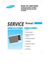
8. Exploded Views and Parts List
8-1 Exploded Views
2
1
3
54
55
4
6
7 8
5
53
12
9 10
13
51
45
11
14
50
49
48
15
47
17
44
19
18
43
42
41
20
65
63
52
40
46
22
16
NC
NO
COM
66
36
21
23
24
25
28
27
31
NC
30
39
NO
COM
29
26
56
38
32
37
33
36
34
35
57
58
59
62
60
64
61
Samsung Electronics
8-1
Exploded Views and Parts List
8-2 Main Parts List
Ref. No.
1
2
3
4
5
6
7
8
9
10
11
12
13
14
15
16
17
18
19
20
21
22
23
24
25
26
27
28
29
30
31
32
33
34
35
36
Parts No.
Description/Specification
Q'ty
DE70-30030N
DE63-90035G
DE61-50074B
DE61-30006A
DE61-70060A
DE47-70031G
DE60-40009B
DE63-20017A
DE60-90006A
DE61-50347A
DE61-50027B
DE39-20058D
DE91-40042A
DE61-30129A
DE31-10077D
DE39-40005B
DE39-40515A
DE61-30054A
DE47-20052A
DE03-30035A
DE92-90421A
DE93-20020A
3405-000178
DE72-60106A
3405-000175
3405-000178
DE66-90054A
DE66-40021A
DE61-50106A
2501-001029
DE26-10042B
DE59-40001A
DE91-70061B
DE26-20142A
DE61-40029A
DE65-20025A
PANEL-OUTER;PURE WHT POWER-KOAT
CUSHION-RUBBER;DFA20 T2 W190 L100 BLK
BRACKET-UPPER;SECC T0.6 W248 L422 M9G45
SUPPORTER-HEATER;ALUMINA 5G 2ND-W/P0
SPRING-PLATE;SK-5 T0.5
HEATER-GRILL;D6.6 230V1280W M9G45 SJH
WASHER-TEFLON;SLOT ID22.2 OD28 T1.2 TEFL
GASKET-HEATER;BRASS T1.5 OD30.5 ID22.5
FLANGE-RING;C3604BD ID22.1 OD26 L4.7 MBG
BRACKET-EARTH;BSS2-A T1.0 W35 L43 MBGF45
BRACKET-HEATER;SECC T1.0 W51 L55 CE945GF
ASSY POWER CORD;KKP-4819D/B232 230V/16A L1700
ASSY NOISE FILTER;DNA-1019(C) 250V 10A C
SUPPORTER-PCB;DASS-T9N
MOTOR-FAN;AMM92-002AUEC 230V50HZ MIN2550
ASSY WIRE HARNESS-D;220V60HZ RE-642/652
ASSY WIRE HARNESS-A;220V/50HZ,E9G88S ELE
SUPPORTER-MGT;SECC T0.6 W33.2 L317 MW563
THERMOSTAT;PW-2N 160/60 TERMINAL-Z BK T2
MAGNETRON;OM75PH((31)ESS
ASSY-COVER AIR;RE-642
ASSY BODY LATCH;RE-43B/90B
SWITCH-MICRO;250V,15A,200gf,SPST-NO
GUIDE-S/W;ABS BLK
SWITCH-MICRO;250V,15A,200gf,SPST-NO
SWITCH-MICRO;250V,15A,200gf,SPST-NO
LEVER-SWITCH;POM(F20-02) 15G NTR RE-330
LATCH-BODY;POM(F20-02) 50G RE-330
BRACKET-HVC;SECC T0.8 W31 L125.8
C-OIL;1.05uF,2100V,BK,35x54x90,20mm
TRANS-H.V;Y9245NTC-1 230V 50HZ AC2230V M
DIODE-H.V;HVR-1X-32B-12
ASSY-H.V.FUSE;THV060T-0750-H 5KV0.75A RE
TRANS-L.V;RE-751STC 230V 50HZ AC11/15.5/
FOOT;DASF-330 RE-909CG
CABLE CLAMP;DAWS-2NB NYLON66 NTR WIRE SA
1
1
1
1
1
1
1
1
1
1
1
1
1
2
1
1
1
1
1
1
1
1
1
1
1
1
1
1
1
1
1
1
1
1
4
2
: Option Parts
8-2
: Warning
Remarks
:Electrostatically Sensitive Devices
Samsung Electronics
Exploded Views and Parts List
8-2 Main Parts List
Ref. No.
Parts No.
37
38
39
40
41
42
43
44
45
46
47
48
49
50
51
52
53
54
55
56
57
58
59
60
61
62
63
64
65
DE64-90024A
DE80-10037A
DE61-50081A
DE93-90003A
DE71-60195A
DE67-40064A
DE91-70155A
DE61-80006B
DE61-80037C
DE39-40012A
DE39-40396A
DE61-50301A
DE32-60013A
DE47-20039A
DE93-90002A
DE72-60035H
DE39-30147A
DE65-20014A
DE74-20011A
DE92-90012A
DE72-80062A
DE74-20022A
DE92-90433A
DE92-90334A
DE92-90510A
DE39-40011A
DE74-20107A
DE63-90070A
: Option Parts
Samsung Electronics
Description/Specification
DECORATION-FOOT;ABS P/WHT 25G E9G88S(SSE
BASE-PLATE;SGCC1-Z T0.8 W336.5 L555
BRACKET-COVER MOTOR;SGCC1-Z T0.6 W219.8
ASSY-ELEVATION;RE-751/652
COVER-CEILING;MICA-SHEET T0.5 W59 L122 W
GLASS-LAMP;GLASS T3.0 W28 L15 RE-751
ASSY-LAMP;RE-652/751 CERAMIC
HINGE-LOWER;ZP2W T3.0 ZN(PLATING) RE-552
HINGE-UPPER;SCP1 T3.0 W26 L76 ZP2C-W MB2
ASSY DOOR;CE979GSE(SCAW) P/WHT HANDLE AB
ASSY WIRE HARNESS-SENSOR;220V/60HZ RE-64
WIRE HARNESS-D;110/220V RE-850V DOM
BRACKET-COVER;SBHG1-A RE-707GMS
SENSOR-GAS;ST-MWO
THERMOSTAT;PW-2N 120/110 V-TYPE
ASSY-BKT TCO;RE-642
GUIDE-AIR;SECC (T)0.6 (W)240 (L)242.5 CE
WIRE LEAD-E;140*120 GRN BLK
CABLE CLAMP;DA-6N NY-66
TRAY-COOKING;GLASS T5.5 PI320 RE-605S
ASSY-TRAY SUB;RE-642
SHAFT-BARBECUE;STS304 D3 L149 W60.25 CE9
TRAY-OIL;GLASS(NEOREX) T5 PI210 600G
ASSY-SHAFT BARBECUE;CE979GSE STS304 D6
ASSY-LEG;M9GF45
ASSY RACK-WIRE;M97G45
ASSY WIRE HARNESS-C;220V/60HZ RE-642
TRAY-BROILER;SPP 0.8T 345 345 345 ENAMEL
CUSHION-DIGITRON;T4 W55 L30
: Warning
Q'ty
Remarks
1
1
1
1
1
1
1
1
1
1
1
1
1
1
1
1
1
1
1
1
1
6
1
1
1
1
1
1
1
:Electrostatically Sensitive Devices
8-3
Exploded Views and Parts List
8-2 Door Parts List
5
4
3
2
1
9
7
8
10
Ref. No.
1
2
3
4
5
7
8
9
10
8-4
Parts No.
DE64-40077A
DE67-20066I
DE64-40076A
DE92-50001A
DE64-40041A
DE64-40175A
DE61-70027A
DE60-60008B
DE68-10001A
Description/Specification
DOOR-A;ABS NTR 160G RE-642
SCREEN-DOOR(B);TEMP-GLASS T4.0 W256.8 L352.5
DOOR-SUB;PC NTR 140G RE-642
ASSY DOOR-E;SELANT BLK RE-642
DOOR-C;PP-A353 BLK MW5630T
DOOR-KEY;POM(TC3005) BLK 13G RE-330
SPRING-KEY;HSW3 PI0.6 D5 BLUING
PIN-HINGE;PI4 L15 NYLON#66 M301TBC NTR
LABEL-BRAND;AL SAMSUNG S/S 8.0 50
Q'ty
Remarks
1
1
1
1
1
1
1
2
1
Samsung Electronics
Exploded Views and Parts List
8-3 Control Parts List
10
9
8
7
2
6
5
4
1
3
Ref. No.
Parts No.
1
2
3
4
5
6
7
8
9
10
11
DE71-60003M
DE72-70087K
DE66-20091F
DE71-60177A
DE64-10049A
DE66-20065A
DE66-20069A
DE66-20064A
DE66-20066A
DE91-10427A
Samsung Electronics
Description/Specification
COVER-PANEL;ABS 2 86.7 186.6
CONTROL-PANEL;ABS 180G P/WHT CE979GSE
BUTTON-START;ABS(LG) SMOG-GRY 3G CE979GSE
COVER-LAMP;POM T1.5 4G
KNOB-COVER;ABS NTR 9G RE-642
BUTTON-SELECT-D;PC NTR 5G RE-642
BUTTON-SELECT-C;PC NTR 6G RE-642
BUTTON-CAP;ABS NTR 6G RE-642
BUTTON-SELECT-B;PC NTR 6G RE-642
ASSY P.C.B-MAIN;AC230V/60HZ S V.F.D CE979GSE
ASSY COVROL-BOX;230V50HZ CE979GSE AMFO
Q'ty
Remarks
1
1
1
1
1
1
1
1
1
1
1
8-5
Exploded Views and Parts List
8-4 Standard Parts List
Parts No.
DE60-20014A
DE60-10082H
DE60-10082H
DE60-10082H
DE60-10082H
DE60-20014A
DE60-10052A
DE60-10080A
DE60-10080A
DE60-10082H
DE60-10122A
DE60-10122A
DE02-00029A
DE60-10003A
DE60-10098A
DE60-10082H
DE60-10072A
DE60-10045A
DE60-10082H
DE60-10082H
DE60-10082H
DE60-10082H
DE60-10018A
DE60-10046A
DE60-10082H
DE60-10012A
DE60-10012A
DE60-10012A
DE60-10013A
8-6
Description / Specification
BOLT-FLANGE;M5 L10 MSWR3 FEFZY
SCREW-A;2S-4X12 TOOTHED
SCREW-A;2S-4X12 TOOTHED
SCREW-A;2S-4X12 TOOTHED
SCREW-A;2S-4X12 TOOTHED
BOLT-FLANGE;M5 L10 MSWR3 FEFZY
SCREW-TAP PH;PH M4 L8 FEFZY
SCREW-WASHER;M5 L12 2S
SCREW-WASHER;M5 L12 2S
SCREW-A;2S-4X12 TOOTHED
SCREW-TAP TH;TAP TH 2-4X8 FE FN
SCREW-TAP TH;TAP TH 2-4X8 FE FN
TAPE-SCOTCHPAR;POLYESTER 3M-893 W50
SCREW-TAPPING;TH + 2S M(4) L(6) STS410 N
SCREW-ASSY TAPTITE;PH TC M4X8 SWRCH18A Z
SCREW-A;2S-4X12 TOOTHED
SCREW-TAP TH;TH M4 L16 FEFZY 2-SLOT
SCREW-TAP PH;PH M3 L6 FEFZY
SCREW-A;2S-4X12 TOOTHED
SCREW-A;2S-4X12 TOOTHED
SCREW-A;2S-4X12 TOOTHED
SCREW-A;2S-4X12 TOOTHED
SCREW-ASSY MACHINE;PH M4X0.7P 8 MSWR10 S
SCREW-TAP PH;PH M3 L8 FEFZY
SCREW-A;2S-4X12 TOOTHED
SCREW-TAP TITE;TH + 3 M4 L10 SWR10 ZPC2
SCREW-TAP TITE;TH + 3 M4 L10 SWR10 ZPC2
SCREW-TAP TITE;TH + 3 M4 L10 SWR10 ZPC2
SCREW-ASSY TAP;TH 2S 4 L12 MSWR3 ZPC3 FI
Q'ty
Remarks
2
5
3
2
2
2
1
4
4
1
1
2
1
2
5
1
4
1
8
1
1
2
2
2
2
1
1
1
4
HI-UPP
OUT-PN
DECO
BD-LA
B/UPP
HI-LOW
B/HI-UP
HVTEIL
MGTEIL
SU-MGT
A/LAMP
B/HEAT
P-CEIL
M/GEAR
HVC
FOOT
SENSOR
BAS-P
CLAMP
CV/AIR
CON-BX
B/EATH
MGT-TC
AIR/G
MEM-PN
NO-FIL
P-CO-E
MO/FAN
Samsung Electronics
9. P.C.B Diagrams
220J
C021
C020
220J
4.194304MHz
9-1 P.C.B Diagrams
Samsung Electronics
9-1
P.C.B Diagrams
9-2 P.C.B Parts List
Parts No.
1003-001033
3501-001007
3710-000132
DE07-10055A
DE07-20135A
DE07-90019A
DE13-20016A
DE13-20017A
DE30-20016A
DE32-10034A
DE34-20071A
DE37-90020A
DE47-40024A
DE61-90161A
DE91-20458A
0401-001002
0402-000559
0403-000150
0403-000525
0501-000283
0501-000388
0502-000303
0504-001014
0504-001015
2001-000004
2001-000273
2001-000290
2001-000290
2001-000323
2001-000429
2001-000429
2001-000435
2001-000515
2001-000613
2001-000613
2001-000780
2001-000786
2001-000904
2003-000220
2004-000195
2004-001976
2004-001977
2201-000144
2202-000127
2202-000780
2401-000150
2401-000247
2401-000466
2401-000725
2401-000914
2401-001412
2802-000161
3404-000282
3711-000262
3711-000881
3711-000940
3711-000999
3711-001038
DE09-30227A
DE13-20007A
DE13-20009A
DE39-60001A
9-2
Description / Specification
IC-SOURCE DRIVER;TD62781AP,DIP,18P,300MIL,OCTAL
RELAY-POWER;12Vdc,200mW,5A,1FormA,8mS,4mS
CONNECTOR-SOCKET;12P,1R,2.5mm,STRAIGHT,SN
V.F.DISPLAY;SVM-4SM01,MWO
LED DISPLAY;LTA-2B01G-07,GRN,4,16,60X65,EU
LAMP-PILOT;PI4.0-1,DC12V,60MA,ORG,DI4.1,L
IC-VOLT REGU;KA7805A,TO-220AB,1A,0/125C
IC-DRIVE;KID65003AP,DIP,16P,STICK,TR-AR
BUZZER;CBE2220BA,STICK
FUSE;FSF,250V,2A,20MM,50F
SWITCH-ROTARY;DC10V,1MA,SH,PA-1005A-003-000
CONNECTOR ASSY;YJN25012,PLATE,73MM,WHT
HOLDER-FUSE;FH-51H,7.5A
HOLDER-DIGITRON;NYLON,T1.5,#6,BLK
ASSY PCB AUTO-MAIN;AC230V/50HZ,CE979GSE
DIODE-SWITCHING;1N4148M,100V,200mA,500mW,3nS,D
DIODE-RECTIFIER;D4G,400V,1A,T-1
DIODE-ZENER;1N4743A,13V,5%,1W,DO-41,TP
DIODE-ZENER;1N4733A,5.1V,5%,1W,DO-41,TP
TR-SMALL SIGNAL;KSA539,PNP,400mW,TO-92,TP,120TR-SMALL SIGNAL;KSC815,NPN,400mW,TO-92,BK,120TR-POWER;KSD882,NPN,1W,TO-126,TP,160-32
TR-DIGITAL;KSR1005,NPN,300mW,4.7K-10K,TOTR-DIGITAL;KSR2005,PNP,300mW,4.7K-10K,TOR-CARBON;200Kohm,5%,1/8W,AA,TP,1.8x3.2m
R-CARBON;100Kohm,5%,1/8W,AA,TP,1.8x3.2m
R-CARBON;10Kohm,5%,1/8W,AA,TP,1.8x3.2mm
R-CARBON;10Kohm,5%,1/8W,AA,TP,1.8x3.2mm
R-CARBON;120ohm,5%,1/4W,AA,TP,2.4x6.4mm
R-CARBON;1Kohm,5%,1/8W,AA,TP,1.8x3.2mm
R-CARBON;1Kohm,5%,1/8W,AA,TP,1.8x3.2mm
R-CARBON;1Mohm,5%,1/8W,AA,TP,1.8x3.2mm
R-CARBON;220ohm,5%,1/8W,AA,TP,1.8x3.2mm
R-CARBON;3.9Kohm,5%,1/8W,AA,TP,1.8x3.2m
R-CARBON;3.9Kohm,5%,1/8W,AA,TP,1.8x3.2m
R-CARBON;470ohm,5%,1/8W,AA,TP,1.8x3.2mm
R-CARBON;47Kohm,5%,1/8W,AA,TP,1.8x3.2mm
R-CARBON;620ohm,5%,1/8W,AA,TP,1.8x3.2mm
R-METAL OXIDE;220ohm,5%,1W,AA,TP,4.3x12mm
R-METAL;100Kohm,1%,1/8W,AA,TP,1.8x3.2m
R-METAL;19Kohm,1%,1/8W,AA,TP,1.8x3.2mm
R-METAL;26Kohm,1%,1/8W,AA,TP,1.8x3.2mm
C-CERAMIC,DISC;100pF,5%,50V,CH,TP,8x3,5
C-CERAMIC,MLC-AXIAL;10nF,+80-20%,25V,Y5V,TP,-,7.5
C-CERAMIC,MLC-AXIAL;100nF,+80-20%,50V,Y5V,TP,3.5x1
C-AL;1000uF,20%,25V,GP,TP,10x16,5
C-AL;100uF,20%,10V,GP,-,6.3x11mm,5m
C-AL;10uF,20%,35V,GP,TP,5x7,5
C-AL;2200uF,20%,35V,GP,-,16x25mm,7.
C-AL;22uF,20%,16V,-,TP,5x11,5mm
C-AL;470uF,20%,35V,GP,TP,10x16,5mm
RESONATOR-CERAMIC;4MHz,0.5%,TP,10.0x5.0x7.5mm
SWITCH-TACT;12Vdc,50mA,120+-30gf,6.2x3.6mm
CONNECTOR-HEADER;1WALL,5P,1R,3.96mm,ANGLE,SN
CONNECTOR-HEADER;BOX,3P,1R,2.5mm,STRAIGHT,SN
CONNECTOR-HEADER;BOX,4P,1R,2.5mm,STRAIGHT,SN
CONNECTOR-HEADER;BOX,5P,1R,2.50mm,STRAIGHT,SN
CONNECTOR-HEADER;BOX,6P,1R,2.5mm,STRAIGHT,SN
IC-MCU;24LC01B/P,DIP,DIP,EEPROM
IC-OP AMP;KA2904,DIP
IC;KA7533,DIP,
WIRE-SO COPPER;PI0.6,SN,T,52MM,TAPING_WIRE
Q'ty
1
2
2
1
1
1
1
1
1
1
1
2
1
1
1
12
10
1
3
1
4
1
2
1
1
2
7
6
6
5
6
1
1
7
2
3
2
1
1
1
1
1
1
2
8
1
1
1
1
1
1
1
10
1
1
1
1
1
I
1
1
62
Remarks
RY05,RY06
CN09,CN10
VFD1
DSP1
LP01
IC01
IC07
BUZ1
ECD1
CN05,CN06
FUSE1
D009,D014~D024
D001,D002,D007,D010~D013,D025~D027
ZD01
ZD02~ZD04
TR06
TR04,TR05,TR07,TR08
TR01
TR03,TR09
TR02
R027
R032,R035
R012,R016,R019,R020,R023,R034,R038
R040,R041,R045,R046,R055,R056
R005~R010
R003,R011,R017,R018,R028,
R029,R036,R048,R052~R054
R004
R047
R001,R002,R013,R014,R021,R022,R033
R037,R039
R030,R031,R044
R050,R051
R015
R049
R025
R024
R026
C024
C017,C019
C005,C008,C013~C016,C018,C023
C002
C006
C010
C001
C020
C004
XTAL
SW01~SW10
CN04
CN03
CN08
CN02
CN07
C06
IC03
IC02
J003~J059,J061~J063,J065~J067
Samsung Electronics
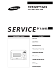
10. Schematic Diagrams
CHOKE P.C.B ASSEMBLY
TCO
MGT
TCO
CAVITY
PRIMARY S/W
BLK
BLK
BRN
BLK
FM
H.V.T
F- MOTOR
D- MOTOR
E- MOTOR
YEL
0V
H.V.D
COM
ORG
NO
NC
E-RELAY
L.V.TRANS
500K
DM
LAMP RELAY
L
MONITOR S/W
BLK
H.V.C
WHT
PCB PARTERN
E
ORG
INRUSH RELAY
MONITOR FUSE
(250V 1.6A)
RESISTOR
WHT
C2
N
GRILL RELAY
BLU
E
IND.
EM
BLU
AC12V
0V
2200pF
220V 50HZ
1mH
RESISTOR
LINE-CAPACITOR 0.1uF
E
HEATER
C1
BLK
GRN
BRN
ORG
RED
RED
2200pF
GRILL
T.C.O
POWER
CORD
BRN
RED
C3
FUSE
BRN
250V 10A
L
BRN
YEL
YEL
F
BLU
BLU
BLU
FA
BLU
POWER RELAY
(SECONDARY INTERLOCK)
MAIN RELAY
MAGNETRON
E/MOTOR
RELAY
H/LAMP
RELAY
GRILL
RELAY
MAIN
RELAY
POWER
RELAY
DOOR SENSING
SWITCH
GND
L.V.T
OUT
PUT
ORG
ORG
1 . INPUT : 230V
2 . DOOR : OPEN
3 . LAMP : ON
GND
WEIGHT
SENSOR
INPUT
(5V)
ELEVATION DOOR
SWITCH
SWITCH
ORG/WHT
NC
NO
COM
BRN
ORG/BRN
NO
COM
WHT/BLK
BRN
PRIMARY LATCH S/W
MONITOR S/W
NO
COM
YEL
YEL
DOOR SENSING S/W
(ASSY MAIN P.C.B)
MAGNETRON
HIGH VOLTAGE
DIODE
TO CHASSIS
FA
F
HIGH VOLTAGE CAPACITOR
ORG
RED
RED
H.V.FUSE
BRN
RED
BLU
SYMBOL COLOR
ORG
ORANGE
BRN
BROWN
RED
RED
BLU
BLUE
HIGH VOLTAGE
TRANSFORMER
Samsung Electronics
10-1